

Page 1

TS-RA1, TS-RA2 and TS-RK
Tank Overll Alarms
Installation Guide
Franklin Fueling Systems • 3760 Marsh Rd. • Madison, WI 53718 USA
Tel: +1 608 838 8786 • 800 225 9787 • Fax: +1 608 838 6433 • www.franklinfueling.com
1
Page 2
Important Safety Messages
INCON equipment is designed to be installed in association with volatile hydrocarbon liquids such as gasoline and diesel
fuel. Installing or working on this equipment means working in an environment in which these highly ammable liquids
may be present. Working in such a hazardous environment presents a risk of severe injury or death if these instructions
and standard industry practices are not followed. Read and follow all instructions thoroughly before installing or working
on this, or any other related, equipment.
As you read this guide, please be aware of the following symbols and their meanings:
Warning
Caution
Danger
Warning
Warning
This symbol identies a warning. A warning sign will appear in the text of this document when a potentially
hazardous situation may arise if the instructions that follow are not adhered to closely. A potentially hazardous
situation may involve the possibility of severe bodily harm or even death.
This is a caution symbol. A caution sign will appear in the text of this document when a potentially hazardous
environmental situation may arise if the instructions that follow are not adhered to closely. A potentially
hazardous environmental situation may involve the leakage of fuel from equipment that could severely harm
the environment.
This symbol identies an electrical danger. An electrical danger sign will appear in the text of this document
when a potentially hazardous situation involving large amounts of electricity may arise if the instructions that
follow are not adhered to closely. A potentially hazardous situation may involve the possibility of electrocution,
severe bodily harm, or even death.
Follow all applicable codes governing the installation and servicing of this product and the
entire system. Always lock out and tag electrical circuit breakers while installing or servicing
this equipment and any related equipment. A potentially lethal electrical shock hazard and the
possibility of an explosion or re from a spark can result if the electrical circuit breakers are
accidentally turned on during installation or servicing. Please refer to the Installation and Owner’s
Manual for this equipment, and the appropriate documentation for any other related equipment, for
complete installation and safety information.
Follow all federal, state and local laws governing the installation of this product and its associated
systems. When no other regulations apply, follow NFPA codes 30, 30A and 70 from the National Fire
Protection Association. Failure to follow these codes could result in severe injury, death, serious
property damage and/or environmental contamination.
Warning
Warning
When the Fuel Management System system is used to monitor tanks containing gasoline or other
ammable substances, you may create an explosion hazard if you do not follow the requirements in
this manual carefully.
All wiring from probes or sensors to the console must be run in conduit separate from all other
wiring. Failure to do so will create an explosion hazard.
2
Page 3

Product Overview and Theory of Operation
The TS-RA1, and TS-RA2 are remote audible and visual alarm units that are used with Fuel Management System
consoles.
The TS-RA1, TS-RA2, and the TS-RK Tank Overll Alarm and Alarm Acknowledge units are mounted near the tank
lling site. If the tank product level reaches the FMS overll alarm setpoint, then the Tank Overll Alarm will become
active. An active Tank Overll Alarm alerts the tank lling attendant to immediately stop the lling operation before a spill
occurs. The TS-RK is an optional remote alarm acknowledge unit. This unit gives the tank lling attendant the means to
silence a Tank Overll Alarm at the lling site. The TS-RK is required when a TS-RA1 or TS-RA2 is connected to a T5
series Fuel Management System console or a Colibri Automatic Tank Monitor.
When in an alarm condition, depressing the acknowledge button on the TS-RK will silence the Tank Overll Alarm at the
tank lling site.
Alarm Specications
The TS-RA1 is a standard intensity, remote alarm device that has a useful signal range up to 50 feet.
Ratings
Input Power 115 VAC (96 to 132vac), 60Hz @ 0.125 amps Maximum
Operating Temperature Range –31 to 150 °F
Humidity Range Up to 95% humidity
Signal outputs Visual (low intensity incandescent lamp) & audio tone (85 dB @ 10 feet)
The TS-RA2 is alarm device that has a strobe-light, and eight user-selectable output tones with two user-selectable sound
intensities. In the high-intensity mode, the TS -RA2 has a useful signal range up to 200 feet.
Ratings
Input Power 115 VAC (96 to 132vac), 60Hz @ 0.125 amps Maximum
Operating Temperature Range –31 to 150 °F
Humidity Range Up to 95% humidity
Signal outputs Visual strobe (15 Candela), and audio tone (99 dB to 75 dB @ 10 feet).
When properly installed, wired, and programmed, this alarm system will help prevent dangerous fuel spills, environmental
contamination, and cleanup costs.
3
Page 4
Installation
Overview
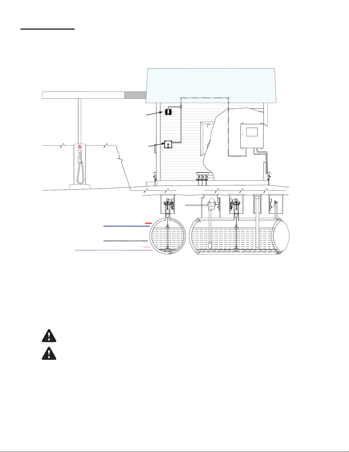
The mounting location of TS-RA1, TS-RA2, TS-RK units should be based on: cable run length, ease of conduit routing,
alarm light visibility, alarm horn audible range limitations, and the distance away from hazardous areas. In addition, the
following limitations and requirements must be met.
(high)WATER
Limit setpoint
HIGH Limit
(Tank full) setpoint
LOW Limit
(Reorder) setpoint
TS-RA1, or TS-RA2
Tank Overfill Alarm
(TS-RA2 shown)
Alarm Acknowledge
HAZARDOUS
(Tank Overfill) setpoint
LO LO Limit setpoint
TS-RK
NON-HAZARDOUS
AREA
AREA
HI HI Limit
Unit
TANK OVERFILL ALARM
MODEL TS-RA2
SACO, MAINE 04072
74 INDUSTRIAL PARK RD.
INTELLIGENT CONTROLS
TANK OVERFILL ALARM
ACKNOWLEDGE
MODEL TS-RK
INTELLIGENT CONTROLS INC.
74 INDUSTRIAL PARK ROAD
SACO, MAINE 04072
Tank Filling Site
HAZARDOUS
AREA
FMS
Console
NON-HAZARDOUS
AREA
Figure 1: TS-RA and TS-RK Installation Overview
• The location of the Tank Overll Alarm and Alarm Acknowledge unit enclosures must be less than 1000 feet away from
the 120 VAC electrical power (source) panel.
• The TS-RA1, or TS-RA2 Tank Overll Alarm unit should be mounted near the fuel tank lling area.
• The alarm light must be visible and the alarm horn must be audible at the fuel tank lling area.
•
These units should be mounted in a protected location that minimizes exposure to direct sunlight, snow and rain.
• The TS-RK Tank Overll Alarm Acknowledge unit should be accessible to the tank lling attendant. Access to the TS-RK
from the lling area must be clear with no obstructions.
DO NOT install the Tank Overll Alarm, or Alarm Acknowledge units in a volatile, combustible, or
Warning
explosive atmosphere. Failure to do so may create an explosion hazard.
Warning
4
Run wiring from the Tank Sentinel console to the TS-RA1 / TS-RA2 Tank Overll Alarm, and TS-RK
Alarm Acknowledge units in separate conduit apart from any other wiring. All conduits must enter
through supplied non-intrinsically safe enclosure knockouts only. Failure to do so may create an
explosion hazard.
Page 5

Mounting the Units
• Mount the TS-RA1, and/or TS-RK units through the four (4)
mounting holes provided in the case under the front cover.
(4) Holes for
#8-32 Mounting Screws
(Flasher)
• Mount the TS-RA2 unit through the two (2) mounting
holes provided.
110 VAC
(LINE)
110 VAC
(NEUT)
GND
EXT
ALARM
CON.
G1
4.22"
107 mm
4.22"
107 mm
Internal View (Cover Removed)
Figure 2: TS-RA1 Mounting Details
(4) Holes For
#8-32 Mounting Screws
F1
2-1
ACKN
SWITCH
2-2
2-3
LATCH
MODE
2-4
4.22"
107 mm
Internal View (Cover Removed)
1-3
1-4
1-5
1-6
1-7
1-8
1-9
LINE1-1
NEUTRAL1-2
GROUND
REMOTE
ALARM
SIGNAL
FLASH
DRIVE
FLASH
SHUNT
OUTPUT
OUTPUT
RETURN
4.22"
107 mm
Figure 3: TS-RK Mounting Details
5.0"
127 mm
0.25 DIA (6.4 MM)
(2) HOLES
Figure 4: TS-RA2 Mounting Details
Wiring the Units
Materials Required
• Wire: 18 to 14 AWG, 300 Volt, type TFFN, THWN,
or THHN (Note: THHN is not available in 18 AWG).
Recommended insulation colors are black, white, green,
and blue.
• Conduit: 1/2 inch, or 3/4 inch (the TS-RA2 has a 1/2 inch
NPT for threaded conduit / tting).
•
Fittings: for conduit used, and conduit hold-down clamps.
• Sealant: waterproof conduit, ttings, tting threads, and
conduit accesses to the building.
• Fasteners: appropriate for the wall construction involved.
Refer to the schematics on the following page for
connection information.
5
Page 6

Schematics
TS-RA1
110 VAC
(LINE)
110 VAC
(NEUT)
GND
EXT
ALARM
CON.
Console Relay Outputs
NC1
C1
NO1
NC2
C2
NO2
2AG 3A Fuse
ACKN
SWITCH
LATCH
MODE
2-1
2-2
2-3
2-4
1-1 LINE
1-2 NEUTRAL
1-3 GROUND
1-4
REMOTE ALARM SIGNAL
1-5
1-6 FLASH DRIVE
1-7 FLASH SHUNT
1-8 OUTPUT
1-9 OUTPUT RETURN
TS-RK
TS-RK and TS-RA1 Wiring Schematic
To 110 VAC
Power Supply
6
Page 7

SW1
1 2 3 4
O
N
See Table below
Console Relay Outputs
NC1
C1
NO1
NC2
C2
NO2
ACKN
SWITCH
LATCH
MODE
TS-RK
N STB
N AUD L
L
TS-RA2
2AG 3A Fuse
2-1
2-2
2-3
2-4
TS-RK and TS-RA2 Wiring Schematic
1-1 LINE
1-2 NEUTRAL
1-3 GROUND
1-4
REMOTE ALARM SIGNAL
1-5
1-6 FLASH DRIVE
1-7 FLASH SHUNT
1-8 OUTPUT
1-9 OUTPUT RETURN
To 110 VAC
Power Supply
TS-RA2 SW1 Switch Position Settings
(factory settings are shown in bold italic)
Sound Ouput
Position 1 Tone Pos. 2 Pos. 3 Pos. 4
Level
High dB ON Horn
ON ON ON
(continuous)
Standard db OFF Bell ON OFF ON
March Time Horn OFF OFF ON
Code-3 Horn ON ON OFF
Code-3 Tone OFF ON ON
Slow Whoop OFF ON OFF
Siren ON OFF OFF
HI/LO OFF OFF OFF
7
Page 8

Setup and Operation
The console will need to be setup for proper alarm
operation.
The steps below show setup via the console touch-screen.
The steps would be the same if logged onto the console
via computer.
Access Setup / Power Supply Module
The screens below show Channel 1 set up to alarm on a
tank overll alarm.
Select Relays
Select the channel that the TS-RK is
wired to. Refer to the wiring schematics.
Setting up Alarm Rules
Navigate back to the setup screen and select rules.
8
Page 9

If a Rule is not already in the system for the alarm you
need, Click on the to Select or create a rule for the Tank
Overfill Alarm.
Navigate back to the Rules setup page and select Actions,
and set the relay to activate.
Select Events
After selecting Events / Event, the following screen shows
the setup for the alarm.
The code could be either High product level or High
product Volume depending on the choice under the Fuel
Management System High Product Limit. Choosing the
incorrect code will lead to the rule not functioning as
designed.
Navigate back to the Rules / Actions page and add another
action.
Set this up the same as the previous screen, but have the
action set to deactivate. This will allow the relay to reset
(the alarm will continue until it is acknowledged).
9
Page 10

Testing the Alarm Wiring
The procedure below is used to verify that the tank
Overll Alarm is wired correctly.
1. Select the Main Menu button.
2. Select Diagnostics.
4. Select the Tank Overll Alarm Relay
5. Select Activate Relay.
3. Select relay
The alarm should now be activated. After the test,
repeat these steps again, but choose DEACTIVATE the
relay.
10
Page 11

Page intentionally blank
11
Page 12

© FFS 2010 000-1027 Rev F
 Loading...