


TSP-HLS
(Standard Sensor) High Level Sensor
Installation Instructions
Franklin Fueling Systems • 3760 Marsh Rd. • Madison, WI 53718 USA
Tel: +1 608 838 8786 • 800 225 9787 • Fax: +1 608 838 6433 • www.franklinfueling.com
Overview
1.86 inch (47.25 mm)
Dia. float
(Black)
Square (33.25 mm)
2 inch NPT fitting
Magnetic reed
float switch circuit
opens when float
moves up
Typical sensor
input interfa ce
(Channel n):
(WHT)
(BLK)
TSP-HLS-XX
CLOSED
OPEN
Float retainer
C-clips
HIGH LEVEL SENSOR
(Standard Sensor)
TSP-HLS
7/8 inch (22.23 mm)
Swage locknuts to set
Actuation length (Float
height alarm setpoint)
adjusted length L
NC
C
GND
TSP-HLS-XX
OPEN
CLOSED
Adjusted
Length L
IN
(White)
CLOSED
O P
E
N
Model number
value indicates
approximate
maximum
adjusted length
in inches
Model number
value minus (-)
length L = Float
height (high alarm
setpoint) in inches
Tank
Eys seal
Fitting
½ or ¾ inch conduit
TSP-HLS
Sensor
Weatherproof
Junction box
Compression
Fitting
(Cord grip)
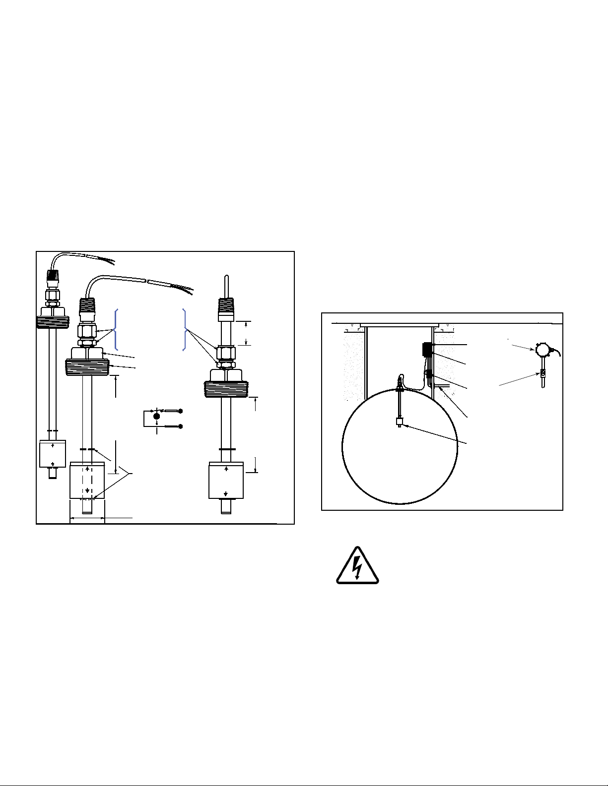
The TSP ‑HLS is a standard sensor that is used to detect
a high liquid level condition within storage tanks (for Class
1, Division 1, Group D Hazardous Area / Environments
such as fuel storage tanks). The sensor is available in two
standard lengths: TSP‑HLS‑15 = 15 inch (381 mm) and
TSP‑HLS‑30 = 30 inch (762 mm). The sensor is supplied
with electrical connectors, 25 feet (7.5 meters) of attached
cable, and a cord‑grip tting.
The TSP-HLS sensor uses magnetic‑oat / reed‑switch
technology for liquid detection. The wetted portion of
the sensor is constructed of stainless steel and nitrophyl
(oat). When the oat rises about ½ inch (12.5 mm), the
magnetically‑sensitive reed switch opens (see Figure 1).
An open circuit is an alarm‑condition (at the intrinsically-
safe, sensor interface terminals inside the Franklin Fueling
Systems ATG console).
Weatherproof junction box, gasket, and cover, plus a •
3/4 to 1/2 inch NPT reducing bushing if 1/2 inch RMC is
used – see the ATG Installation Guide for recommended
electrical Junction Boxes
Wire: THHN, TFFN or THWN, 18 AWG, White & Black, •
or Alpha Cable # 58411, 0.114” O.D. (2.9 mm) – 1,500
feet (457 meters) max. length If using nonmetallic (PVC)
conduit, Alpha cable 58411 must be used.
Slip joint pliers to seat the no‑strip, self‑sealing wire •
connectors – connectors are supplied with the sensor
Standard adjustable or pipe wrench for a 2 inch square •
tting
U.L. classied thread sealant or pipe dope.•
Tank Strapping Table (Tank Chart) to set the • High Level
Alarm
Two 7/8 inch (23 mm) hex wrenches to adjust • FLOAT
HEIGHT.
Installation Sequence:
1. Install manhole.
2. Install conduit, EYS ttings, and weatherproof
junction box
Figure 1: TSP-HLS Dimensions and Setup
Testing the TSP -HLS
Rotate the sensor 180 degrees (oat up) to cause an
alarm at the ATG console. Test the sensor for proper
operation on a yearly basis, or as required per local code.
Materials & Data Required
• Optional – TSP‑DB1 Epoxy Seal kit for no‑strip electrical
connectors – recommended for sites: within ood
zones, high groundwater tables, with poor drainage, or
when Junction Boxes are not used
1/2 or 3/4 inch NPT (National Pipe Thread, tapered), •
Rigid Metal Conduit (RMC) or nonmetallic (PVC) conduit
if allowed by local code.
EYS Seal ttings and epoxy to ll the tting after •
operational testing is completed.
2
Figure 2: TSP-HLS Installation
3. Turn off power.
ELECTRICAL DANGER Avoid electrical
shock hazards: ensure all power
going to the ATG console is turned off,
tagged, and locked-out at the power
panel before doing any maintenance or
installation work at the ATG console
4. Pull the sensor cables through the cord grip tting
at the junction box. Leave enough cable to allow
installation of the sensor in the tank: the sensor
will be tested before actual in‑tank installation.
5. Tighten cord‑grip tting at the junction box and trim
the wire / cables within the junction box to a 6 or 8
inch (15 or 20 cm) length, then splice the sensor
and console cable / wires together as shown in
Figure 3.
6. Turn console power on for sensor testing.

7. Test sensor (rotate oat end up to verify that an
2 wires/cable from console
2-conductor cable from sensor
J-box
From 2-wire sensor
SENSOR N
IN(WHT)
Only remove the
jumper link between:
in (wht) & gnd (blk),
when a sensor
channel is wired
Note: The
PWR (red)
terminal is
not used with
2-wire sensors
GND(BLK)
PWR(RED)
PWR(RED)
SENSOR 1
IN(WHT)
GND(BLK)
Insert the unstripped wires fully
into the self-sealing, no-strip
electrical connector.
Use slip-joint pliers and seat
the black portion to make a
good electrical connection
IN
(WHT)
GND
(BLK)
Caution
Warning
Caution
Warning
alarm is produced at ATG console). If the sensor
does produce an alarm, seal EYS seal ttings
with epoxy.
8. Turn power off again if other devices are to be
installed (Repeat Step 3)
9. Reinstall all safety covers and guards, junction
box gasket and covers – use pipe-dope to seal all
tting threads.
10. Adjust the ACTUATION LEVEL (FLOAT HEIGHT)
to equal the High Level Alarm level for this Tank .
a. Loosen the ⅞ inch swage locknuts
b. Move the shaft to set oat height
c. Retighten the swage locknuts to hold position.
11. Install the manhole cover.
12. Record the location where the sensor was
installed (TANK), and the Float Height = High
Level Alarm Level on the back page of this
document. This information is needed when
programming the ATG.
13. Turn power on and program the ATG – Refer to
Sensors in the console Setup / Programming &
Installation manuals.
Note: Seal all threaded ttings and conduit ttings to
produce a weatherproof seal.
Figure 3: Sensor Wiring
General Installation Notes
Fill the bottom of the manhole with crushed stone to
facilitate drainage. Do not cover the sensor or bung access
hole with ll material, it must remain accessible for sensor
installation and for service / testing.
Plan your conduit routing. Dig trenches as necessary
to install conduit from each manhole junction box to the
Intrinsically Safe (I.S.) knockouts at the ATG console. The
conduit may enter the manhole either from its bottom or
through its side. A junction box inside of the building as a
pull box to combine several sensor cables. If this is done,
then only one I.S. conduit knockout will be used.
You must install a weatherproof, electrical junction
box inside each manhole. The junction box should be
installed high on the manhole wall to prevent it from being
submerged during heavy rains.
It is the installer’s responsibility to
comply with all applicable federal, state
and local codes. Failure to do so may
create an Environmental Hazard.
Conduits must have EYS seal ttings
installed in accordance with NFPA
70 (National Electric Code) and NFPA
30A (Automotive and Marine Service
Station Code). Failure to seal conduits
in accordance with NFPA 30A, and
NFPA 70 could allow ammable vapors
to travel through the conduit in the
ATG console. An explosion could result
causing serious injury, property loss,
or death.
Electrical Wiring
Reference the ATG Installation Manual and see Figure 3
(above) for TSP‑HLS sensor wiring details. The two‑wire
TSP‑HLS sensor does not have a red (power) conductor,
therefore, the PWR (RED) interface terminal at the console
is not used. If a 3-conductor Alpha cable is used, the red
conductor can be clipped or taped back on both ends.
3

Sensor Location Float Height / Notes
©2008 FFS 000‑1347 Rev E
 Loading...