

Page 1

TSP-HIS (BriteSensor®)
Hydrostatic Interstitial Sensor
Installation Instructions
Franklin Fueling Systems • 3760 Marsh Rd. • Madison, WI 53718 USA
Tel: +1 608 838 8786 • 800 225 9787 • Fax: +1 608 838 6433 • www.franklinfueling.com
Page 2
Overview
21.7 INCH
(551.2 mm)
2.5 Inch (63.5 Mm)
Max. Dia. [ Typ ]
TSP-HIS
Hydrostatic
Interstitial Sensor
(BriteSensor
®
)
4 to 4.5 INCH
(102 TO 114 mm)
Normal Brine Level
Datum
8.6 INCH
(225 mm)
Ref.
7.5
Inch
(190.5
mm)
High
Brine
Level
1.0 INCH
(25.4 mm)
Low
Brine
Level
11.8 inch
(299 mm)
2.38 Inch (60.5 Mm)
DIA. [ TYP ]
6.25 TO 5.75 INCH
(159 TO 146 mm)
Normal Brine Level
11.0 Inch
(279.4
mm)
High
Brine
Level
18.76 INCH
(476.5 mm)
REF.
TSP-HIS-XL
Extra Long
Hydrostatic
Interstitial Sensor
(BriteSensor
®
)
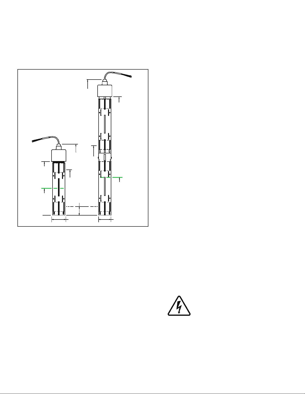
The TSP-HIS sensor is an intelligent BriteSensor ® that
is used to monitor the brine levels inside hydrostatic
interstitial reservoirs of double walled tanks. A low brine or
high brine level are alarm conditions and indicate a leak in
either the outer tank or the inner storage tank. The TSPHIS-XL sensor is an extra long version of this sensor
(see Figure 1).
Both sensors have upper and lower magnetic reed switch
oats, which detect a change in the interstitial reservoir
brine level. The sensors use intrinsically safe (I.S) leak
detection circuits and are approved for use in these Class
1, Division 1, Group D Hazardous Areas.
Like other BriteSensors, these sensors have a
microprocessor that analyze the environmental conditions
at the sensor and transmits data to the Automatic Tank
Gauge console. The TSP-HIS sensors detect and
communicate: a HIGH BRINE alarm level, a LOW BRINE
alarm level, and a NORMAL no-alarm state (lower oat
submerged & upper oat dry), plus it transmits a specic
sensor ID code.
Included with the sensor are: no-strip electrical wire
connectors, 25 feet of cable (attached), a Model ID tag,
and a cord-grip tting for connection to a weatherproof
electrical junction box (see diagrams). Be sure to check
the Model ID tag before installing the sensors as they can
be confused with the similar looking TSP-DDS and TSPDTS sensors.
2
Figure 1: TSP-HIS Dimensions
A vented riser cap (model TSP-KV4) is required
for this installation so the brine level can rise or fall
(hydrostatically) along with atmospheric pressure without
building up positive or negative pressures inside the
interstitial area.
Testing the TSP-HIS
Dip the sensor in 2 inches (50.2 mm) or water and remove
after one minute to produce a LOW BRINE alarm. Rotate
the sensor 180 degrees (oat up) to cause a HIGH BRINE
alarm at the ATG console. Test the sensor for proper
operation on a yearly basis, or as required per local code.
Materials Required
Optional – TSP-DB1 epoxy seal kit for no-strip electrical •
connectors – recommended for sites: within ood zones,
high groundwater tables, with poor drainage, or when
Junction Boxes are not used.
1/2 or 3/4 inch NPT (National Pipe Thread, tapered), •
Rigid Metal Conduit (RMC), or non-metallic (PVC)
conduit if allowed by local code.
EYS Seal ttings and epoxy to ll the tting after •
operational testing is completed.
Weatherproof junction box, gasket, and cover, plus a •
3/4 to 1/2 inch NPT reducing bushing if 1/2 inch RMC is
used – see the ATG Installation Guide for recommended
electrical junction boxes
Wire: THHN, TFFN or THWN, 18 AWG: Red, White, & •
Black, or Alpha Cable # 58113, 0.131 O.D. – 1,500 feet
(457 meters) max. length. Alpha cable #58113 (INCON
P / N 600-0063) must be used when using nonmetallic
(PVC) conduit.
Slip joint pliers to seat the no-strip, self-sealing wire •
connectors – connectors are supplied with the sensor
Standard adjustable or pipe wrench for a 2 inch square •
tting.
UL classied thread sealant or pipe dope.•
TSP-KV4 vented riser cap (order separately)•
Installation Sequence:
1. Install manhole.
2. Install conduit, EYS ttings, and weatherproof
junction box (Refer to Figure 2).
3. Shut off power to the ATG.
ELECTRICAL DANGER. To avoid
electrical shock hazards, ensure all
power going to the ATG console is
turned off, tagged, and locked-out
at the power panel before doing any
maintenance or installation work at the
ATG console
4. Pull the sensor cable through the cord grip tting
at the junction box (leave enough cable to allow
for the installation of the sensor in the interstitial
area). Before pulling wires, mark them to avoid
confusion when connecting to the ATG console.
Page 3

5. Tighten cord-grip tting at the junction box and trim
Brine
Fill
Level
Manhole
Cover For
14 inch (35.56 cm)
Min. Dia. Manhole
Brine Filled
Interstitial Area
Brine Fill Level:
= 4 inches (102 mm) For
Standard TSP-HIS Sensors,
or
= 6 inches (152 Mm) For
Extra Long TSP-HIS-XL
Sensors
4 inch (101.6 mm)
Riser Pipe
1/2 or 3/4 inch
Conduit
Eys Seal
Fitting
Clean Fill Material
(Gravel Typical)
Weatherproof
Junction Box
Concrete Slab
Per NFPA 30
Compression
Fitting
(Cord Grip)
TSP-KV4 Vented
Riser Cap
W/cord Grip
Thru Holes for
Locking Cap
Vent
Lever
Double Wall Tank
TSP-HIS
Sensor
Interstitial
Reservoir
TO 3-W I RE SEN SOR
3 W IR ES/CA BLE FROM CONS OLE
3-C ONDUCTO R CABLE FROM SENSOR
SENSOR N
IN(WHT)
Only remove the
j
umper link between:
IN (wht) & GND (blk),
wh en a sensor channel is wired
Note: The PWR (red) terminal
is only used wi th 3-w ire sensors
GND(BLK)
PWR(RED)
PWR(RED)
SENSOR 1
IN(WHT)
GND(BLK)
Insert the unstripped w ires
fully into the self-sealing,
no-strip electrical connector.
Use slip-joint pliers and
seat the black portion
to
make a good electrical connection
GND
(BLK)
PWR
(RED)
IN
(WHT)
the wires / cables within the junction box to a 6 or
8 inch (15 or 20 cm) length, then splice the sensor
and console cable / wires together as shown in
Figure 3.
6. Turn power on to console to test sensor.
7. Test sensor (the sensor will produce a Low Brine
Alarm out of the brine solution, and a High Brine
Alarm when the senor rotated with the cable
down to verify that an alarm is produced at ATG
console). If the sensor does produce these alarms,
seal EYS seal ttings with epoxy.
8. Turn power off again if other devices are to be
installed.
9. Reinstall all safety covers and guards, junction
box gasket and covers – use pipe-dope to seal all
tting threads.
General Installation Notes
WARNING
The bottom of the manhole should be lled with crushed
stone to facilitate drainage. Do not cover the sensor
or bung access hole with ll material, it must remain
accessible for sensor installation and for service / testing.
Plan your conduit routing. Dig trenches as necessary
to install conduit from each manhole junction box to the
Intrinsically Safe (I.S.) knockouts at the ATG console. The
conduit may enter the manhole either from its bottom or
through its side. A junction box inside of the building as a
pull box to combine several sensor cables. If this is done,
then only one I.S. conduit knockout will be used.
WARNING
You must install a weatherproof, electrical junction
box inside each manhole. The junction box should be
installed high on the manhole wall to prevent it from being
submerged during heavy rains.
It is the installer’s responsibility to
comply with all applicable federal, state
and local codes. Failure to do so may
create an environmental hazard.
WARNING Conduits must have EYS
seal ttings installed in accordance
with NFPA 70 (National Electric Code)
and NFPA 30A (Automotive and Marine
Service Station Code). Failure to seal
conduits in accordance with NFPA 30A,
and NFPA 70 could allow ammable
vapors to travel through the conduit in
the ATG console. An explosion could
result causing serious injury, property
loss, or death.
10. Install the manhole cover.
11. Record the location where the sensor was
installed on the chart on the last page of these
instructions.
12. Turn power on and program the ATG – Refer
to all information relating to sensors in the
Setup / Programming & Installation manuals.
Figure 2: TSP-HIS Installation
CAUTION Seal all threaded ttings and conduit
connections to produce a weatherproof seal during
installation / maintenance.
Figure 3: TSP-HIS Sensor Wiring
Electrical Wiring
Reference the ATG Installation Manual and see Figure 3
(above) for TSP-HIS sensor wiring details.
3
Page 4

Record Sensor Location
Sensor Channel # / Notes
© 2008 FFS 000-1348 Rev E
 Loading...