

Page 1

TSP-DMS
Discriminating Magnetostrictive Sensor
Installation Manual
Manual # Revision Date Changes from Previous Revision
000-0269 C April 2011 Added note to remove tie and added tank interstitial installation
Franklin Fueling Systems • 3760 Marsh Rd. • Madison, WI 53718 USA
Tel: +1 608 838 8786 • 800 225 9787 • Fax: +1 608 838 6433 • www.franklinfueling.com
Page 2
INCON equipment is designed to be
Warning
installed in association with volatile
hydrocarbon liquids such as gasoline
and diesel fuel.
Installing or working on this equipment means
working in an environment in which these highly
ammable liquids may be present. Working in such
a hazardous environment presents a risk of severe
injury or death if these instructions and standard
industry practices are not followed. Read and follow
all instructions thoroughly before installing or working
on this, or any other related, equipment.
Note: The TSP-DMS is for connection to INCON
T5 series consoles only.
The Discriminating Magnetostrictive Sensor TSP-DMS
is designed to detect water or fuel in a sump or a tank’s
interstitial space, and give notication through the fuel
management console.
The sensor also has anti-tamper capability that will
give notication through the console if it is lifted from its
installed position.
Magnetostrictive Sensor Installation
The TSP-DMS comes supplied with a model 283-0205
Unistrut 2" pipe clamp assembly. If the sump has a Unistrut
already installed, mount the 2" clamp to the Unistrut and
slide the DMS sensor so the wire is at the top, and the
bottom is tight against the bottom of the sump.
Unistrut Channel
from kit TSP-KS
TSP-DMS
Sump Bottom
Figure 2. TSP-DMS Sensor Installed
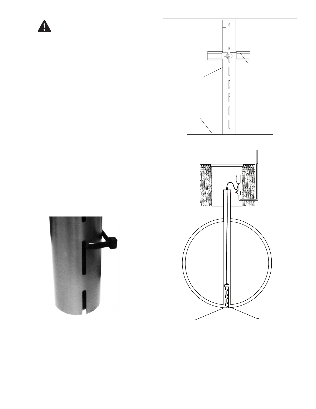
TSP-DMS Tank Interstitial Installation
Note: Be SURE to remove the factory-installed tie
wrap before installation.
Figure 1: Tie Wrap to remove
TSP-DMS Sump Installation
If the sensor is mounted in a sump that does not have a
Unistrut channel installed, order part number TSP-KS,
and follow installation instructions. Make sure that the
sensor is touching the bottom of the sump before and after
tightening the mounting bracket.
Tank
Bottom
Figure 3: Tank Interstitial Installation
TSP-DMS
SENSOR
Inspect the Tank Interstitial riser and conrm the diameter
is 3" or larger. To make sure the Sensor is installed at the
Bottom of the interstitial shaft you will need to make a mark
on the sensor wire.
Page 3

First Measure the height of the riser, measuring from the
After Crimp
To
Console
To
TSP-DMS sensor
Before Crimp
End view of splice
Black wire of senso
r
Both shield wires
Red wire of
field cable
Black wire of
field cable
Red wire
of sensor
Connect bare metal shielding together
top opening to the tank, make note of this length, and now
nd the outside diameter of the tank. Add the riser length
to the diameter of the tank: this should be the total depth
from the interstitial opening to the bottom of the interstitial
shaft. Now you will need to subtract the length of the
sensor you are installing.
• The TSP- DMS-12 is 22”
The mark on the sensor wire needs to be:
Riser Length + Tank Diameter-Sensor Length
When lowering the sensor, the marked point should stop at
the top of the riser entrance conrming the sensor is at the
bottom of the interstitial space.
Slowly lower the TS-DMS down the shaft until the mark
made is near or at the opening of the interstitial shaft.
Feed the sensor wire through cap and compression
gland (purchased locally) making sure the sensor wire is
still slack indicating you have not pulled off the bottom.
Tighten compression gland. Do no tighten the cap down
at this time as the sensor will need to be tested once all
programing and learning has been completed. The sensor
is now ready to be wired and connected to the console.
and at the console with the Tank / Sensor number.
Figure 4: Model TSP-DMS — Cable Wire Splicing
Splice the sensor cables together at the weatherproof
junction box located in the manhole as shown in Figure 4.
Black wires from sensor and console are spliced together
with the shield (bare) from both.
Red wires from sensor and console are spliced together.
If a white wire is present on the sensor cable, cut it back.
Use the No-Strip Electrical connectors supplied in the
installation kit to make all connections.
TSP-DMS Wiring
Use cables and wires compliant with national and local
codes. Franklin Fueling Systems recommends using
the types of cable list in Table 1 up to the recommended
lengths.
Cable Type O.D. Distance ft (M)
* Belden No. 87760 0.12” (3 mm) 260 (80)
* Belden No. 87761 0.12” (3 mm) 400 (120)
* Belden No. 88761 0.12” (3 mm) 400 (120)
* Belden No. 89182 0.31” (7.9 mm) 1500 (450)
* These cables can be ordered from INCON.
Use only cable as specied or equivalent to the above.
Do NOT exceed cable lengths of 1500 feet.
WARNING: Use of sub-standard cables, or exceeding
maximum cable lengths may result in faulty operation, can
create an explosion hazard, and WILL void the warranty.
Conduit
The above-listed wiring is for use when run in Rigid Metal
Conduit. If local codes allow use of nonmetallic (PVC)
conduit, use Alpha Wire #58411 (INCON #600-0062).
Cable Color Code
Use the following color code for the sensor wiring:
RED or YELLOW WIRE = + (Signal)
BLACK WIRE = – (Signal Ground)
BARE = SHLD (Shield)
Label Cables
Label all sensor cables within the weatherproof pull box,
Table 1: Sensor Cables
Note: Do not use wire nuts to make sensor connections.
Use the crimp splice connectors supplied with the TSPDMS, or equivalent, only. Failure to use the appropriate
crimp-splice connectors will result in faulty operation and
will void the warranty.
Note: Avoid wiring errors by using consistent color codes
when making sensor cable connections. Always
use the Red (or yellow) wire for the + signal. Always
use the Black wire for – signal ground. And always
use the bare wire as the shield.
Note: Make sure that all conduits, conduit ttings, junction
box ttings and hole plug threads are waterproofed
with pipe-dope. Wet wiring will result in faulty
operation.
Caution
Make sure that the sensor cable is
wired correctly. Reversing the plus
and minus terminals can damage the
Intrinsically Safe circuits.
Warning
Only one sensor should be connected
per channel. Connecting multiple
sensors to a single cable or channel in
the FMS console may cause damage to
the unit and may create an explosion
hazard, and will result in improper
system operation.
Page 4

Console — DMS Sensor Wiring Connections
The wiring should connect to the probe module. The probe
module may also have wiring from vapor ow meters
and / or other probes (See Figure 5).
Remove 1-1/2” (38 mm) of jacket from each sensor cable,
and strip off 3/16” (5 mm) of insulation from the end of
each conductor.
In the console, start wiring from channel 1 on probe
module and work up from there. Wire the three wires of
the cable to the PROBE interface terminal set (channel) as
described below:
1) Connect the black wire to the minus – (BLK)
terminal.
2) Connect the red (or yellow) wire to the plus +
(RED) terminal.
3) Connect the cable shield to the same - (BLK)
terminal as the black wire.
Repeat this wiring procedure until all sensors are wired to
the probe input channel terminals (+, – / SHLD). A sensor
or probe can be wired to any input probe channel and will
operate normally after it is setup / programmed correctly.
Module
–Blk
12
+Red
–Blk
11
+Red
–Blk
10
+Red
–Blk
9
+Red
–Blk
8
+Red
–Blk
7
+Red
–Blk
6
+Red
–Blk
5
+Red
–Blk
4
+Red
–Blk
3
+Red
–Blk
2
+Red
–Blk
1
+Red
Probe
RUN
ERR
Non-Hazardous
Location
SHLD
- (BLK)
+ (RED)
Hazardous Location
Class I, Division 1, Group
D, Group IIA, Zone 0
SHLD
Figure 5: Sensor Connection to Console
- (BLK)
SHLD
- (BLK)
TSP-DMS
+ (RED)
Probe
+ (RED)
Vapor Flow Meter
©2011 FFS 000-0269 Rev C.
 Loading...