

Page 1
TS-LS300 Auto-Learn
®
User’s
Pressure-Based
Electronic Line Leak Detector
System
Guide
Part Number: 000-0140 Rev. C
©
Copyright
March 2008
Page 2
NOTICE
INCON has strived to produce the finest possible manual for you, and to ensure
that the information contained in it is complete and accurate. However, INCON
makes no expressed or implied warranty with regard to its contents. INCON
assumes no liability for errors or omissions, or for any damages, direct or
consequential, that result from the use of this document or the equipment which it
describes.
This document contains proprietary information and is protected by copyright. All
rights are reserved. No part of this document may be reproduced in any form
without the prior written consent of INCON.
INCON reserves the right to change this document at any time without notice.
Need Help ? Mail Address (no packages):
INTELLIGENT CONTROLS INC
PO BOX 638
SACO ME 04072
Office Hours: 8 am to 5 pm EST, Monday through Friday
Sales – Orders 24 hour Technical Service
Delivery Schedules: RMA, Application Help:
Fax: (207) 283-0158 Fax: (207) 282-9002
Phone: (800) 872-3455 Phone: (800) 984-6266
email: sales@incon.com email: tech@incon.com
INCON is a wholly owned subsidiary of Franklin Electric and is member of the:
Franklin Fueling Systems Group. Visit our web site at:
T ank Sentinel®BriteSensors® and INCON®are registered trademarks of Intelligent Controls, Inc.
System Sentinel™ and System Sentinel ™ are trademarks of Intelligent Controls, Inc.
LS300 Auto-Learn® is a registered trademark of FE Petro®.
Copyright© 2003 – all rights reserved.
www.franklinfueling.com
INSIDE FRONT COVER
LS300 User’s Guide
Page 3

Table of Contents
Preface ............................................................................................................ P-1
Safety............................................................................................................... 1-1
Mechanical Installation..................................................................................... 2-1
Electrical Installation & Wiring ......................................................................... 3-1
Line Calibration................................................................................................ 4-1
LS300 Console Operation ............................................................................... 5-1
TS-LS300 Troubleshooting guide .................................................................... 6-1
Appendix A Specifications.................................................................................A-1
TABLE OF CONTENT Page TOC-1
LS300 User’s Guide
TOC
Page 4
P Preface
— Important – Read
NOTE
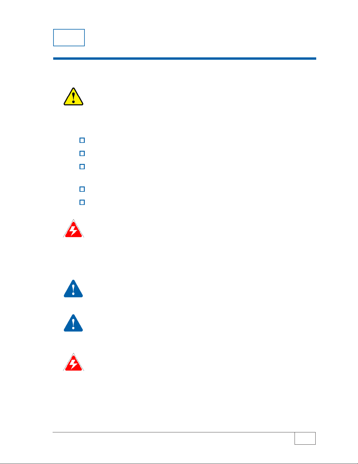
Graphic Symbol Conventions
Read and follow the entire instructions in this manual before installing or working on this equipment.
Certified Installer/Service Person: Only an INCON certified installer or service person is allowed
to access both the user interface kepad and areas internal to the TS-LS300 console.
Station Owner/Operator: The station owner or operator of the TS-LS300 console is only allowed to
access the user interface keypad. Access to areas internal to the console is strictly prohibited.
NOTE
Important information, tips, and hints are highlighted by the note graphic.
CAUTION
be followed to avoid faulty equipment operation, or environmental hazards, or personnel injury!
WARNING
must be followed to avoid faulty equipment operation or explosion. If ignored, severe injury or death
may result!
DANGER
be followed to avoid an explosion or fire hazard. If ignored, severe injury or death will result!
ELECTRICAL DANGER
contain instructions that must be followed to avoid an electrical shock. If ignored, severe injury or
death may result and even severe damage to electronic equipment.
messages are highlighted by the CAUTION graphic and contain instructions that should
messages are highlighted by the DANGER graphic and contain instructions that must
Earth Ground Terminal
messages are highlighted by the WARNING graphic and contain instructions that
messages are highlighted by the ELECTRICAL DANGER graphic and
Pressure High/Pump ON
A
T
Ground Terminal
Alarm/Failed Test
Testing/Passed Test
Pressure Low/Pump OFF
LS300 User’s Guide
H
or
Horn/Audible Alarm
Test/Reset
Single Phase Alternating
Current
PREFACE Page P-1
P
Page 5

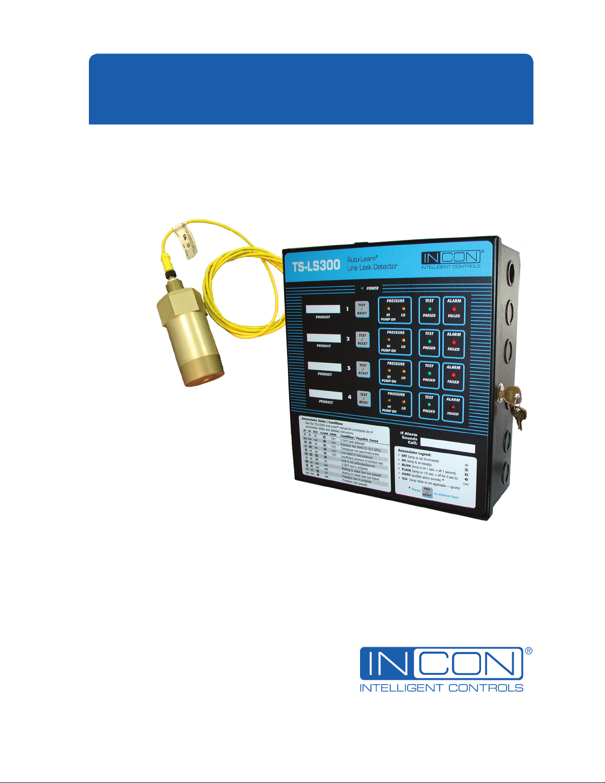
General Overview
The TS-LS300 Auto-Learn® Line Leak Detector (LLD) is a precision electronic line-leak-detection
system that is produced for installation in a petroleum pumping system. The Auto-Learn Line Leak
Detector automatically monitors at certain times and will indicate pipeline leaks should a leak occur.
An alarm indicator lights, an audible alarm horn sounds, and positive pump shutdown happens when
a leak is detected. This complies with U.S. EPA requirements 280.41(b) & 280.44(a) for automatic
leak detection in pressurized piping. After installation, the user of the leak detector must monitor the
system to ensure that any leak alarm and pump shutdown (indicating a leak in the pipeline) is dealt
with promptly.
The Auto-Learn LLD can detect a leak from the STP check valve to the solenoid valve at the
dispenser, assuming no other Normally Closed valve is in the pipeline system. The Auto-Learn LLD
does not detect leaks from the fuel storage tank or the from the submersible pump before the output
check valve. The Auto-Learn LLD is used with motor fuels.
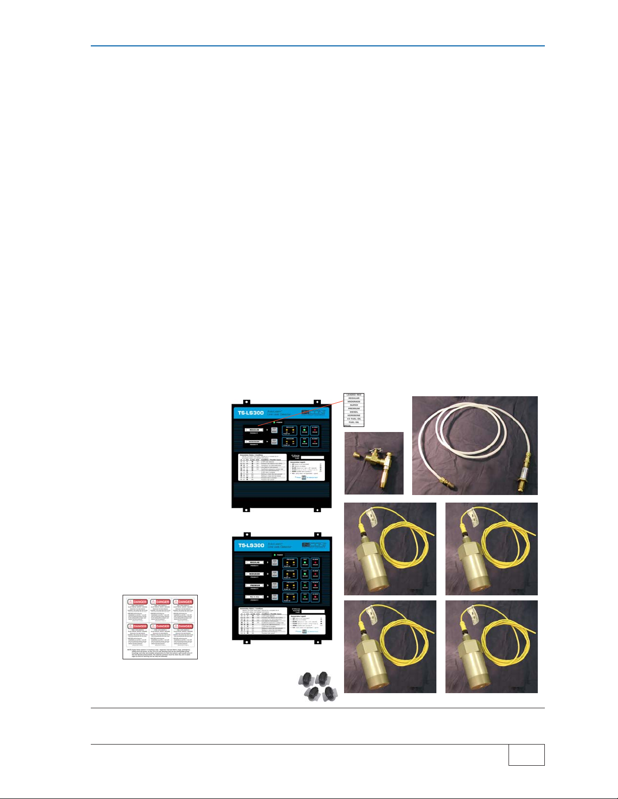
The system includes a 2 or 4 channel LSU300 console with stick-on Product ID Labels, Danger
Labels, one Auto-Learn Calibration Kit (leak-generator), 2 to 4 Needle Valve Kits, no-splice
connectors, and 2 to 4 LSU300 pressure-transducers as specified at time of order. Each channel will
monitor one piping system or product line. All line leak detectors must be tested upon start-up, and
routinely thereafter (at least annually) under NFPA standards. These NFPA and other industry
testing practices must be followed by the installer and the end user. A leak detector is not a
substitute for compliance with prudent industry practices. Fuel inventory reconciliation checks must
be performed on a daily basis by comparing dispenser meter totalizers with fuel volume changes in
the underground tank.
The Auto-Learn LLD pressure transducer is manufactured in two different versions:
1) The TS-LSU300 pressure transducers are Intrinsically Safe (I.S.) for U.S. and
international markets and are for use only with the TS-LS300 version console
2) The TS-LSU300E pressure transducers are Explosion Proof for Canadian and
U.S. markets and are for use only with the TS-LS300E version console
Wire Intrinsically Safe LSU300 transducers only with TS-LS300 consoles... physical
separation of transducer cables from non-intrinsically safe circuits is also required.
NOTE
Wire Explosion Proof LSU300E transducers only with TS-LS300E consoles in accordance
with applicable standards... use of explosion proof J-Boxes and conduit fittings in hazardous
locations. This wiring does not require separation from other non-intrinsically safe circuit wiring. This
method can be used for retrofit installations where separate conduit is not available.
This Installation and Owner’s Manual gives instructions for, site assessment and preparations,
installation, wiring, calibration, and operation. Each section gives step by step process to
successfully complete the section. A troubleshooting guide is included if difficulties are encountered.
P
Page P-2 PREFACE
LS300 User’s Guide
Page 6
Each product line must be precision tested and verified free of leaks before any component of the
LS300 system is installed. After verification, the LS300 Auto-Learn
®
system is installed, wired, and
calibrated. The supplied leak-generating device/calibration kit* is attached to a needle valve, and the
appropriate line channel selector switch is placed in the learn position at the console. Each line is
calibrated separately, one at a time, to “learn” the parameters and characteristics of a line with a
known induced leak-rate.
At each STP housing, the needle valve kits* are assembled and installed in the pressure test ports,
and the LSU300 pressure-transducers are installed in 2 inch NPT line leak detector ports (LSU300
cable length must not exceed 500 feet).
After a line is calibrated the leak-generator device is moved to the next product line for Auto-Learn
calibration. The entire process is repeated until all lines are separately calibrated and the console is
left in the Run – Detect mode.
The front panel has a power on light and 4 status-lights per line. The status lights show currently
running line leak tests, faults, and alarms. Fault-alarms will cause indicator lights to blink or flash.
Certain alarms will also activate the internal alarm horn. Manual line leak tests may be started and
* The needle valve kit and the leak generating device/calibration kit have not been
evaluated by Underwriters Laboratories
.
STICK-ON
DANGER
2 CHNL LS300
2 CHNL
3 OR 4 CHNL
NO-STRIP
SPLICE
PRODUCT
ID
NEEDLE
VALVE
LEAK GENERATING
DEVICE
LSU300 TRANSDUCER
# 3 with
3/ 4 Chnl
# 4 with
4 Chnl
Figure P-1 LS300 LLD System Components
PREFACE Page P-3
LS300 User’s Guide
P
Page 7

the alarm horn can be silenced by pressing the Test/Reset push-button on the appropriate channel,
which will silence the alarm horn and can start a new manual Line Leak Test.
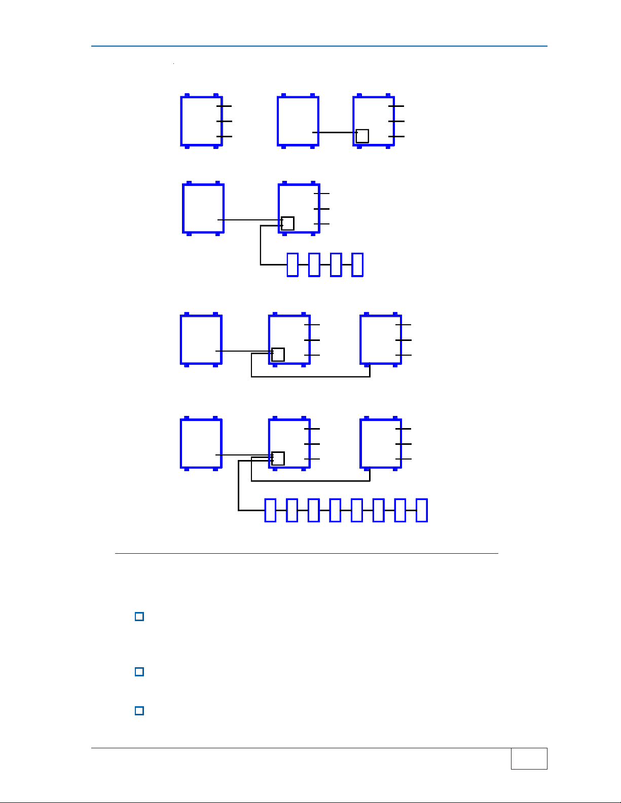
The LS300 System Applications – 5 block diagrams
The block diagrams on the next page, Figure P-1, show the 5 different applications possible with this
equipment. Only block diagram #1, Basic Auto-Learn electronic Line Leak Detector (LLD) console,
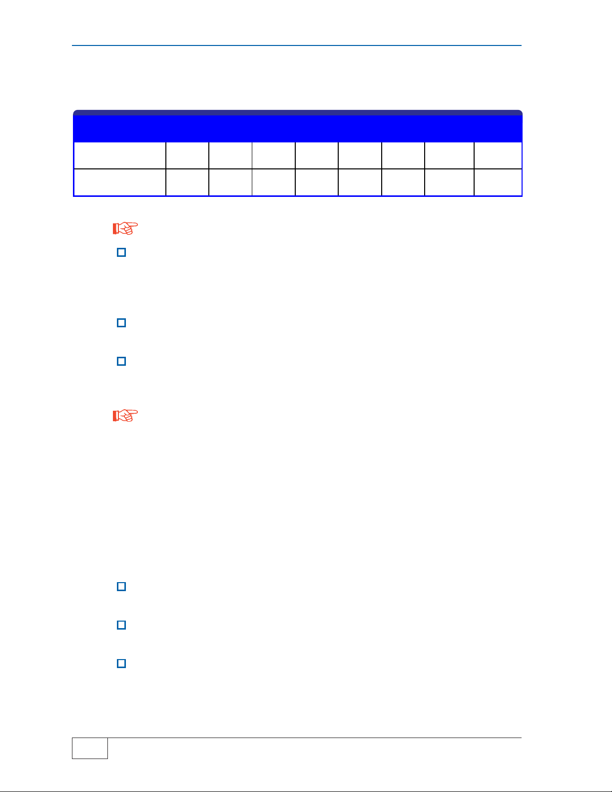
TABLE P-1 Console Channel X - Test/Reset PB
Push
#
Effect
Times
1
2
3
4
is covered in this manual, See TS-TPI, TS-1001-, TS-2001, or STP controller User guides for more
information on the other applications. The possible Applications are:
Gros s (3 gph / 11 Lph) Line Leak Tes t
Monthly (0. 2 gph / 0 . 8 L ph) Line L eak Test
Annual (0. 1 gph / 0. 4 Lph) Line Leak Tes t
Silences Alarm Horn
See the
Operation
section in this
manual or the
Quick
Reference
Guide
# 1 Basic Auto-Learn electronic Line Leak Detector (LLD) console
# 2 One LS300 Auto-Learn console with TS-TPI plus an INCON ATG (Automatic Tank
Gauge) console for LLD interface
Note: TPC is the designation for a Turbine Pump Controller throughout this
manual
# 3 One LS300 Auto-Learn console with TS-TPI for Turbine Pump Controller (TPC)
interface and an INCON ATG console for LLD and Pump Controller interface
P
# 4 Two LS300 Auto-Learn consoles for support of up to 8 lines: one console has the
TS-TPI interface circuit board enabling connection to the other LS300 console via a
special RS-232 cable and to the INCON ATG console via RS-485 communication
for LLD interface
# 5 Two LS300 Auto-Learn consoles for line leak detection of up to 8 lines: one console
has the TS-TPI interface circuit board for connection to the other LS300 console via
a special RS-232 cable and connects to the INCON ATG console via RS-485
communication for LLD interface and for Turbine Pump Controller control
Page P-4 PREFACE
LS300 User’s Guide
Page 8
TS-LS300
Auto-Learn
Console
1
Inputs (#1-4):
Lines (#)
Hooks (#)
Power
TS-ATG
Console
2
LLD
RS485
TS-LS300
Auto-Learn
Console
TS-TPI
PCB
Inputs (#1-4):
Lines (#)
Hooks (#)
Power
TS-ATG
Console
3
TS-ATG
Console
4
TS-ATG
Console
5
LLD
RS485
LLD
RS485
LLD
RS485
TS-LS300
Auto-Learn
Console
TS-TPI
PCB
TPC TPC
TS-LS300
Auto-Learn
Console #1
TS-TPI
PCB
TS-LS300
Auto-Learn
Console #1
WITH
TS-TPI
PCB
Inputs (#1-4):
Lines (#)
Hooks (#)
Power
TPC TPC
Inputs (#1-4):
Lines (#)
Hooks (#)
Power
Inputs (#1-4):
Lines (#)
Hooks (#)
Power
TS-LS300
Auto-Learn
Console #2
TS-LS300
Auto-Learn
Console #2
Inputs (#5-8):
Lines (#)
Hooks (#)
Power
Inputs (#5-8):
Lines (#)
Hooks (#)
Power
TPC TPC TPC
TPCTPC TPC TPC TPC
Figure P-1 Auto-Learn System Applications (5) – Block Diagram
Site Survey & Assessment
A precision line test must be conducted before installing the LSU300 transducer for
the first time and before replacing any line leak detector that is indicating a leak to
assure line integrity .
Before installation of Auto-Learn system verify that the equipment is proper for the
site.
Check that the pipeline volume (based on length, internal diameter, and pipe type)
is less than the 3rd party approval (see Table P-2). Third party tests have approved
PREFACE Page P-5
LS300 User’s Guide
P
Page 9
the use of Auto-Learn in rigid pipelines up to 163-gallon capacity and in flex
pipelines up to 39.5 gallons.
TABLE P-2 Third Party Approved — Max Pipe Lengths:
Pipe Diameter I.D.
Max. Rigid Pipe
Lengthl
Max. Flexible Pipe
Length
NOTE
Maximum pipe lengths are equivalent to: 163 gallons (617 liters) in rigid piping
systems and 39.5 gallons (149.5 liters) in flexible piping systems.
A minimum static line pressure of 17.5 psi is needed for Auto-Learn LLD to perform
a Gross (3gph) and Monthly (0.2 gph) line-leak test. If the static line pressure is
greater than 17.5 psi but less than 22.5 psi, the Annual (0.1 gph) line-leak test can
not be performed.
For each pipeline verify that the pressure is 25 psi or greater when the pump is
“ON,” and that the pressure holds at 22.5 psi or greater when the pump is “OFF.”
Use a pressure gauge to verify that each line is stable after 5 minutes of pump-off.
The pressure change in a stable pipeline must be less than 5 psi.
NOTE
To maintain proper pipeline pressure with a FE Petro STP, use FE Petro’s standard check valve.
With Red Jacket STP, use the adjustable functional element with pressure adjusted to meet the
Auto-Learn LLD pressure requirements. For proper operation of the Red Jacket functional element
the pump “ON” pressure must be at least 2 psi greater than pump “OFF” line pressure. See Red
Jacket instructions for complete details before starting.
1"
(25 mm)
3995'
(1217 m)
968'
(295)
1 1/2"
(38 mm)
1775'
(541 m)
430'
(131 m)
1 3/4"
(44 mm)2"(51 mm)
1304'
(397 m)
316'
(96 m)
998'
(304 m)
242'
(74 m)
2 1/2"
(64 mm)3"(76 mm)4"(101 mm)5"(127 mm)
639'
(195 m)
154'
(46 m)
443'
(107 m)
107'
(33 m)
249'
(76 m)
60'
(18 m)
159'
(48 m)
38'
(12 m)
Materials & Tools Required
In addition to what is supplied with the LS300 Auto-Learn electronic LLD system (the LS300
Console, LSU300 Transducers, stick-on Danger Labels, Needle Valve Kits, Leak Generator Device –
Calibration Kit, stick-on Product ID Labels, and this manual) the following materials and tools are
required:
Socket set, extension, and square socket for 1/4 inch (6.5 mm) square-head hole
plugs (Non-sparking)
Wrench, 2 3/8 inch open end hex wrench or adjustable 0-70 mm wrench (Nonsparking)
Assorted non-sparking adjustable open-end wrenches, including pipe wrenches and
slip-joint pliers (Non-sparking)
P
Page P-6 PREFACE
LS300 User’s Guide
Page 10
Petroleum absorbent and absorbent rags, and approved waste containers
Gasoline/oil resistant, non-hardening, UL Classified, Teflon Pipe Dope / Thread
Sealant (Gasoila) to seal threads of the LSU300 transducer & Needle Valve Kit
Single scale, general purpose, Pressure Gauge (1/4 inch NPT, 0 to 60 psi in 1 psi
increments) for temporary installation during site assessment and during the
LS300 Auto-Learn calibration step
Approved Gasoline/fuel oil container test tank (minimum 5-gallon capacity) to
collect product from the leak generator calibration kit during Auto-Learn calibration
Level, measuring tape, scribes/punch, and fasteners for wall mounting of console
Threaded 3/4 inch NPT (DN20NPT) rigid metal conduit, conduit bender, conduit
cutter, couplings, fittings, plus Epoxy Y Seal fittings (EYS), quick set epoxy, and
Conduit Clamps/Hangers
Explosion / Weather Proof J-Boxes
LSU300 Transducer Cable: Belden shielded cable #9363-22AWG,
#9364-20AWG, or #9365-18AWG or equivalent (#9365-18AWG is preferred)
RS-485 Cable – for ATG and Pump Controllers – use the Transducer Cable above
#9365-18AWG preferred. Shield wire is connected to RS-485 “Ground” terminal on
the TPI board (The other end of the sheild is not connected).
Wire for LS300 Auto-Learn LLD console: Power Input and Hook Inputs — per code
Electricians tools (Safety Lockouts &Tags, assorted wire strippers, cutters, various
size – flathead and phillips-head screwdrivers, multimeter with leads & clips, strainrelief fittings, spanner wrenches, slip-joint pliers [Non-sparking] conductor markers,
and indelible fine point marking pens)
PREFACE Page P-7
LS300 User’s Guide
P
Page 11
1 SAFETY
Safety First – Before Working on this Equipment
CAUTION
hydrocarbon liquids such as gasoline and diesel fuel. Installing or working on this equipment
means working in an environment in which these highly flammable liquids or vapors are
present. This presents a real risk of severe injury or death if these instructions and standard
industry practices are not followed.
Prohibit access to the work area to certified and trained installers/service personnel
Identify and mark the perimeter of the work area with signs, safety-cones and colored safety tape
Prevent unauthorized vehicle access (block access) into the work areas by using barriers,
barricades, and service trucks
Use only non-sparking tools when working in these Hazardous Areas
Occasionally check for presence of hydrocarbon vapors in containment sumps
ELECTRICAL DANGER
working on this equipment: turn off all submersible pump power / pump controller power, Tank
Sentinel console power, LS300 electronic Line Leak Detector console power, and dispenser power
at the electrical power panel(s). Lock out and tag these circuit breakers in the off position to prevent
accidental / unauthorized circuit breaker closure. Failure to turn off and lock out power would result
in severe injury or death!
This equipment is designed to be installed in association with volatile
Lethal Electrical Shock Hazard! Before installing, servicing, or
WARNING
installed or serviced. DO NOT smoke while working on or near this equipment and only use nonsparking tools. Failure to follow this instruction could result in a serious fire or explosion.
WARNING
product and the entire system. When no other regulations apply, follow NFPA 30, 30A, and 70
from the National Fire Protection Association. Failure to do so could result in serious
property damage, environmental-contamination, and severe injury or death.
ELECTRICAL DANGER
described in this manual, otherwise lethal electrical-shock-hazards could exist, which may cause
injury or death. Note: circuit breaker contact(s) can fail to open even when the circuit breaker lever
indicates off.
Highly flammable vapors may be present in the environment where this equipment is
Follow all federal, state, and local laws governing the installation of this
Verify that no voltage exists before working-on, or wiring-to circuits
SAFETY Page 1-1
LS300 User’s Guide
1
Page 12
ELECTRICAL DANGER
Electronic line leak detectors start submersible pumps
automatically to run leak-tests at full line pressure. Automatic pump starts occur between
periods of product dispensing when there is no product being dispensed. Before performing
any installation or service (such as replacing fuel-filters) – tag and lock-out all electrical power
sources to the submersible pump(s), pump controllers, and dispensers
and relieve fuel-line pressure.
Failure to turn off power and relieve fuel-line pressure before work is started can result in:
pressurized fuel spills (an environmental hazard associated with costly clean-ups), and fire or
explosion hazard that may result in injury or death.
NOTE
Multiple INCON Danger stickers are supplied with electronic line
leak detectors. Apply these stickers on the pump relay box
cover, in locations near dispenser fuel-line filters, plugs,
emergency safety-shut-off valves, on or near the Leak Sensing
Unit Transducer (at the submersible pump housing), and other
serviceable components of a fuel line (where a spill would
occur if the line became pressurized). The selected surfaces
must be clean, dry, and in plain sight so that the label can be
DANGER
FIRE, EXPLOSION &
ELECTRICAL SHOCK HAZARD
Electronic line leak detector
installed—the pump may start at any
time and pressurize the fuel lines.
•
BEFORE performing any
installation or service — turn off/
lock out electrical power sources
to the submersible pump(s), and
relieve fuel-line pressure.
INCON PN 240-1175 Rev. D
read, and followed.
WARNING
The fuel line from the submersible pump to the dispenser, may be under
pressure. Turn off all pump power and relieve pipeline pressure (reference and follow the
pump manufacturer’s directions about how to do this). If the line leak detector/plug (or any
other part of the submersible pump and fuel line) is removed without first relieving pressure,
then a product leak will occur. This could cause an environmental, fire, or explosion hazard,
and may result in injury or death.
WARNING
Avoid personnel injury or property damage: keep moving vehicles and
unauthorized personnel out of the hazardous work area. Use Safety Cones, Barricades,
Warning Signs, and Safety Tape, and block access with Barricades / service trucks to the
work area to avoid injury or property damage.
WARNING
Be careful not to cause sparks when working on fuel dispensing equipment
(volatile fuel may be within the pump’s leak detector port). Allow no source of combustion
near the work area. Failure to follow these directions may cause an explosion hazard, which
could result in property damage and death.
WARNING
During the Calibration/learn process, ALWAYS secure the line leak generator in
the appropriate container. When the submersible pump is turned on, a fine stream will be
sprayed out the orifice of the line leak generator. This stream can cause movement of the line
leak generator and possibly come out of the container. This product stream can cause
physical injury and environmental hazards.
1
Page 1-2 SAFETY
LS300 User’s Guide
Page 13
WARNING
container on the ground when filling with gasoline. Use only containers approved for motor
fuel storage.
Prevent static electric sparks and possible explosions — always have fuel test
CAUTION
Electric Code (NEC), and the Automotive and Marine Service Station Code (NFPA 30A in the
USA) before installation or maintenance. This installation is designed for submersible pumps
which have a Pump Control box in the station. If a pump control box does not exist, then the
system must be retrofitted to add a pump control box in the facility to comply with Codes.
CAUTION
operating the LSU for long periods while under water. Drain the sump and manhole
immediately into a holding tank for disposal per Codes.
WARNING
equipment is being installed or serviced. Do not smoke while working on or near this
equipment. Use only non-sparking tools. Failure to follow this instruction could result in a
serious fire or explosion.
CAUTION
vapors, if vapor levels are unsafe ventilate the sump with fresh air. While working in the sump
periodically check the atmosphere in the sump, if vapors reach unsafe levels exit the sump
and ventilate it.
CAUTION
or around a containment sump. Electronic and electrical petroleum monitoring equipment is
often housed in containment sumps designed to trap hazardous liquid spills and prevent
contamination of the environment.
Refer to all applicable Federal, State, City and local codes, your National
Although the LSU300 is water resistant, INCON does not recommend
Highly flammable vapors may be present in the environment in which this
Before entering a containment sump check for the presence of hydrocarbon
ALWAYS have a second person standing by for assistance when working in
WARNING
If these vapors are inhaled they could cause dizziness or unconsciousness. If the vapors
were ignited they could explode causing serious injury or death.
ELECTRICAL DANGER
installing or servicing this equipment, pumps and related equipment. A potentially lethal
electrical shock hazard and the possibility of an explosion or fire from a spark can result if
the electrical circuit breakers are accidentally turned on during installation or servicing.
During normal operation Auto-Learn will turn on the STP as part of its leak testing process. A
shock, fire or environmental contamination hazard could result from Auto-Learn attempting to
turn on the STP while equipment is being serviced.
These containment sumps can trap dangerous amounts of hydrocarbon vapors.
ALWAYS lock out and tag electrical circuit breakers while
SAFETY Page 1-3
LS300 User’s Guide
1
Page 14
CAUTION
ALWAYS cleanup and dispose of used absorbent/rags and petroleum resistant gloves in
approved waste containers. Cleanup refuse and dispose of these immediately to avoid
personnel injury from vapors or direct skin contact to also avoid possible fire or
environmental safety hazards.
This leak detector is designed for use in specific applications and in compliance with
industry standards and practices. Using it in applications for which it was not designed or
failure to follow industry standards and practices may cause the product to malfunction or
fail.
Petroleum is carcinogenic – use adequate protection to avoid health hazards.
CAUTION
LS300 Console and the LSU300 Transducers. Lengths exceeding the 500 feet limit (152 m)
could cause unreliable system operation, which may result in creation of environmental
hazards in the event that a leak is undetected.
DO NOT exceed the 500 feet limit (152 m), maximum distance, between the
1
Page 1-4 SAFETY
LS300 User’s Guide
Page 15
2 Mechanical Installation
Mechanical Installation Sequence:
Follow the instructions here to mount the LS300 Auto-Learn console and to install the LSU300 Leak
Sensing Unit transducers, and Needle Valves at each STP containment sump (see Figure 2.2 for
typical finished installation). Be sure to ask the electrician to do any “electrical” type of work when
appropriate.
1.) Mount the LS300 Console on a vertical surface using appropriate fasteners, level, and between 2
feet (0.6 m) and 6 feet (1.9 m) high for use (see Figure 2-1 and make allowances for conduit runs
and fittings at the left, right and bottom sides)
NOTE
The LS300 AutoLearn console must be located in a pollution degree 2 environment per IEC60664 in
contries requiring CE compliance.
2.) At the electrical power panel: locked-out & Tag POWER OFF for the STP’s, Pump Controllers, and
Dispensers
DANGER
at full line pressure. Automatic pump starts occur between periods of product dispensing when there
is no product being dispensed. BEFORE performing any installation or service (such as
replacing fuel-filters) – tag and lockout all electrical power sources to the submersible
pump(s), pump controllers, and dispensers and relieve fuel-line pressure. Failure to turn off
power and relieve fuel-line pressure before work is started can result in: pressurized fuel
spills (an environmental hazard associated with costly cleanups), and fire or explosion hazard
that may result in injury or death.
WARNING
from moving vehicles. This equipment is usually mounted underground, therefore, reduced visibility
puts service personnel working on this equipment in danger from moving vehicles entering the work
area. Use Safety Cones, Barricades, Warning Signs, and Safety Tape, and block access with
Barricades / service vehicles to the work area to avoid injury or property damage.
Electronic line leak detectors start submersible pumps automatically to run leak-tests
Avoid personnel injury or property damage: ALWAYS secure the hazardous work area
3.) Relieve pipeline pressure to 0 psi per manufacturers recommendation and capture any product that
escapes or use absorbent rags to clean up any product spills and dispose of properly (FE Petro
Pumps: open Manual Pressure Relief valve / MPR valve... Red Jacket Pumps: Turn Functional
Adjustment element to 0 psi, if no adjustment exists – remove and replace with an adjustable
functional element)
WARNING
Turn off all pump power and relieve pipeline pressure (reference and follow the pump manufacturer’s
directions about how to do this). If the line leak detector/plug (or any other part of the submersible
pump and fuel line) is removed without first relieving pressure, then a product leak will occur. This
could cause an environmental, fire, or explosion hazard, and may result in injury or death.
The fuel line from the submersible pump to the dispenser, may be under pressure.
MECHANICAL INSTALLATION Page 2-1
LS300 User’s Guide
2
Page 16
4.) Remove other in-line leak detection equipment before installing the LSU300 Auto-Learn LLD
5.) Apply UL Classified Gasoline/Oil resistand teflon pipe dope thread sealant to the threads of the
LSU300 Transducer and use a 2-3/8 inch open-end wrench to install it in the Leak Detector Port of
the STP housing (see Figure 2-2)
6.) Apply UL Classified Gasoline/Oil resistand teflon pipe dope thread sealant, assemble, and install the
supplied Needle Valves in the Line Pressure Test Port of the STP and close all Needle Valves (see
Figure 2-2)
7.) Install Couplings, threaded Rigid Metal Conduit (RMC), and Explosion/Weather Proof Junction
Boxes (J-Boxes) in the STP sumps (see Figure 2-2).
8.) Install threaded RMC and EYS fittings along with Transducer Cables (Belden #9365) from LS300
console to the Explosion/Weather Proof J-Boxes (have the licensed electrician splice the cables
together. If this wiring is Intrinsically Safe it MUST NOT be run with any Explosion Proof wiring or
other non-Intrinsically Safe wiring!).
9.) After all LSU300 Leak Sensing Units (transducers) have been installed, check to see that all Needle
valves are closed, and that the system is ready to be pressurized to check for the absence of leaks.
10.) After the installation is checked and all personnel are clear, have the electrician turn on power at the
Power Panel for the STP (Submerged Turbine Pumps and Dispensers).
11.) Turn on the STP at the dispenser (do not deliver product) and check for leaks at each Sump... if
there are any leaks, immediately turn off power, lockout and tag at the Power Panel, use absorbent
rags to clean up the product spills and dispose of properly, and repair the leak(s) and repeat step 10
and step 11 until no leaks remain.
13.) Clean areas where the Danger Labels will be placed so the adhesive backing will stick to a dry
surface that is clean and free of petroleum.
14.) Cleanup and dispose of installation materials, petroleum absorbent and waste material in
appropriate containers.
15.) Stick the supplied Danger Labels (PN: 240-1175) to clean dry areas near
Dispenser Fuel Filters, Pump Controllers, and on the Cable of the
LSU300 Transducer and on the STP housing.
DANGER
FIRE, EXPLOSION &
ELECTRICAL SHOCK HAZARD
Electronic line leak detector
installed—the pump may start at any
time and pressurize the fuel lines.
•
BEFORE performing any
installation or service — turn off/
lock out electrical power sources
to the submersible pump(s), and
relieve fuel-line pressure.
INCON PN 240-1175 Rev. D
2
Page 2-2 MECHANICAL INSTALLATION
LS300 User’s Guide
Page 17

7.00 (178 mm)
1.50
(38mm)
TYP.
13.38
(340
mm)
REF
11.75
(298
mm)
REF
HINGE SIDE of
CONSOLE DOOR
11.00 x 12.00
(280 x 305 mm)
CONSOLE DEPTH
4.00 (102 MM)
REF
1.00
(25 mm)
TYP.
THRU MOUNTING HOLES
0.31 (8 mm)
TYP. FOUR PLACES
12.75
(324
mm)
0.31
(8 mm)
TYP.
10.75 (273 mm) REF
Optional
TS-TPI to
TS Console
Figure 2-1 LS300 Console Mounting Dimensions & Knockout Locations
RS232 Comm Port
MECHANICAL INSTALLATION Page 2-3
LSU300
Transducers
Dispenser
Hooks
Input
Power
L
LS300 User’s Guide
D
TS-LS300 Console
Dimensions
in inches and (mm) –
Enclosure Only:
H
11.75H x 10.75L x 3.75D
(298H x 273L x 95D)
With Door Closed:
12H x 11L x 4D
(305H x 279L x 102D)
Dual-Sized Conduit Knockouts:
1/2 or 3/4 inch NPT
(DN13NPT or DN20NPT)
2
Page 18

3/4 INCH
NPT
(DN20NPT)
2-3/8
INCHES
(69.85 mm)
ACROSS
FLATS
(NEEDL E
VALVE KIT) @
LINE PRESSURE
TEST PORT
NEEDLE VALVE
ACCESSORY
KIT
(UNASSEMBLED)
REF: 020-1029
1 REQ'D AT
EACH
STP HOUSING
LSU300
TRANSDUCER
6.25
INCHES
(158.75
mm)
LSU300
Leak
Sensing
Unit
Transducer
2 INCH NPT
(DN50 NPT)
5.13
INCHES
(130.18
mm)
See Figures
3-2 and 3-3
for Electrical
installation details
and CE approval notes
STP
HOUSING
NORMAL
OPERATIONAL
VIEW
Figure 2-2 Needle Valve Kit & LSU300 Mounting
2
Page 2-4 MECHANICAL INSTALLATION
LS300 User’s Guide
Page 19

3 Electrical Installation & Wiring
Electrical Installation & Wiring Sequence:
Basic Installation & Wiring
Follow the instructions here to wire the LS300 Auto-Learn console, the
LSU300 Transducers from each STP containment sump, the Dispenser
Hook Inputs, and Console Power Input. (see Figure P-1 & Figure 3-1).
NOTE
Ask the service tech to do “mechanical - pump/dispenser” work if
appropriate.
1.) All cables from the LSU300 transducer to the LS300 console must be installed in metal conduit in
countries requiring CE compliance. Power and communication wires do not need metal conduit
unless it is required by local code.
WARNING
from moving vehicles. This equipment is usually mounted underground, therefore, reduced visibility
puts service personnel working on this equipment in danger from moving vehicles entering the work
area. Use Safety Cones, Barricades, Warning Signs, and Safety Tape, and block access with
Barricades / service vehicles to the work area to avoid injury or property damage.
2.) At the electrical power panel: locked-out & Tag POWER OFF for the STP’s, Pump Controllers, and
Dispensers.
ELECTRICAL DANGER Hook inputs are 120/240 Vac. Disconnect all high voltage sources before
accessing internal electronics
Avoid personnel injury or property damage: ALWAYS secure the hazardous work area
TS-LS300
Auto-Learn
Console
1
Inputs (#1-4):
Lines (#)
Hooks (#)
Power
DANGER Electronic line leak detectors start submersible pumps automatically to run leak-tests at
full line pressure. Automatic pump starts occur between periods of product dispensing when there is
no product being dispensed. BEFORE performing any installation or service (such as replacing
fuel-filters) – tag and lock-out all electrical power sources to the submersible pump(s), pump
controllers, and dispensers and relieve fuel-line pressure. Failure to turn off power and
relieve fuel-line pressure before work is started can result in: pressurized fuel spills (an
environmental hazard associated with costly cleanups), and fire or explosion hazard that may
result in injury or death.
3.) If not done during Mechanical Installation, chapter 2, Run 3 conductor shielded cable from each
Explosion proof/Weatherproof Junction Box in the STP sump where the LSU300 Transducer is
installed, to the LS300 console for Transducer wiring leaving about an 8 inch (203 mm) service loop
(Figure 3-2 & 3-3). Label/Mark each cable jacket with the Tank # / LSU300 Transducer number.
ELECTRICAL INSTALLATION & WIRING Page 3-1
LS300 User’s Guide
3
Page 20

Optional
TS-TPI to
TS
Console
RS232 Comm
Port
LSU300
Transducers
Dispenser
Hooks
Input
Power
L
D
H
Auto-Learn
TS-LS300
TS ATG
Console
NON-HAZARDOUS AREA
Line Leak Detector
Annunciator States/Conditions
FE Petro Models: SCI & VFC4
Turbine Pump Controllers (TPC)
Annunciator Legend
LS300
AutoLearn
Console
LS300
Auto-Learn LLD
Console
LSU300
LLD
Transducer
HAZARDOUS AREA CLASS 1, DIVISION 1,
GROUP C & D
MANHOLE & COVER
STP Power
STP
UST
o
r
t
e
P
E
F
Figure 3-1 Typical – Partial Installation & LS300 Console Conduit Designations
3
Page 3-2 ELECTRICAL INSTALLATION & WIRING
LS300 User’s Guide
Page 21

NOTE
TS-LS300
Annunciator States/Conditions
R
Auto-Learn
Line Leak Detector
POWER
PRESSURE
TEST
/
1
RESET
HI
PUMP ON
PRESSURE
TEST
/
2
RESET
HI
PUMP ON
PRESSURE
TEST
/
3
RESET
HI
PUMP ON
PRESSURE
TEST
/
4
RESET
HI
PUMP ON
Wire Intrinsically Safe LSU300 transducers only to
TS-LS300 version consoles in conduit apart from non-intrinsically safe
wiring. DO NOT run intrinsically safe wiring in the same conduit with non-
intrinsically safe wiring.
INTELLIGENT CONTROLS
ALARM
TEST
PASSED
LO
TEST
PASSED
LO
TEST
LO
PASSED
TEST
PASSED
LO
Annunciator Legend
FAILED
ALARM
FAILED
ALARM
FAILED
ALARM
FAILED
LS300 Auto-Learn
Line Leak Detector
Console (CU)
3/4 inch NPT Conduit
and Fittings
(DN20 NP T )
for I.S. Wiring O nly
- Typical -
Beldon #9363-22 AWG,
#9364-20 AWG, #9365-18AWG
or equivalent recommended.
Max Cable length is 500 feet.
EYS (Epoxy Y Seal)
Fitting TYP
RED
RED
WHT
BLK
SHIELD
SHIELD
TO SPLICE:
INSERT
UNSTRIPPED
WIRES & USE
SLIP-JOINT
PLIERS TO SEAT BLACK PIECE
Follow all federal, state, and local
laws & codes governing the
install ation of this product & the
entire system.
Maximum safe area voltage must
not be greater than 250 Vrms.
WHT
BLK
3 CONDUCTOR
CABLE 6FT
(1.83 meters)
Supplied
Syphon
Plug
Tank
Plug
No-Strip Elect rical
Connectors inside
Weather
Proof J-Box
(Junction Box)
5 FT (1 .5 3 m e te r s)
MAX from LSU300
Transducer
STP
HOUSING
LSU300
Pressure
Transducer
NOTE
Coupling
For CE
compliance the
cables from the
console to the
LSU300
Transducer must
be installed in
metal conduit,
rigid or flexible
Figure 3-2 LSU300 Intrinsically Safe Wiring w/ No-Strip Wire Splice at
Weatherproof Junction Box
ELECTRICAL INSTALLATION & WIRING Page 3-3
LS300 User’s Guide
3
Page 22

NOTE
Wire Explosion Proof LSU300E transducers only to TS-LS300E consoles in accordance with
applicable standards. Explosion proof J-Boxes and conduit fittings must be used in this
application in hazardous locations. This wiring does not require separation from other non-
intrinsically safe wiring.
This method can be used for retrofit installations where separate conduit is not available.
R
Annunciator Stat es/Conditions
Auto-Learn
Line Leak Detector
POWER
PRESSURE
TEST
/
1
RESET
HI
PUMP ON
PRESSURE
TEST
/
2
RESET
HI
PUMP ON
PRESSURE
TEST
/
3
RESET
HI
PUMP ON
PRESSURE
TEST
/
4
RESET
HI
PUMP ON
INTELLIGENT CONTROLS
TEST
PASSED
LO
TEST
PASSED
LO
TEST
PASSED
LO
TEST
PASSED
LO
Annunciator Legen d
ALARM
FAILED
ALARM
FAILED
ALARM
FAILED
ALARM
FAILED
LS300E Auto-Learn
Line Leak Detector
Console (CU)
Beldon #9363-22 AWG,
#9364-20 AWG, #9365-18AWG
or equivalent recommended.
Max Cable length is 500 feet.
RED
3/4 inch NPT Conduit
(DN20NPT)
w/ Explosion Proof
Fittings
- Typical -
EYS (Epoxy Y Seal)
Fitting TYP
TS-LS300
RED
WHT
BLK
SHIELD
SHIELD
TO SPLICE:
INSERT
UNSTRIPPED
WIRES & USE
SLIP-JOINT
PLIERS TO SEAT BLACK PIECE
Follow all federa l, st a te , an d lo c al
laws & codes governing the
installation of this product & the
entire system.
Maximum safe area voltage must
not be greater than 250 Vrms.
WHT
BLK
3 CONDUCTOR
CABLE 6FT
(1.83 mete rs)
Supplied
Syphon
Plug
Tank
Plug
No-Strip Electrica l
Connectors inside
Explosion Proof
J-Box
(Junction Box)
5 FT (1.53 meters)
MAX from LSU300E
Transducer
Cou p ling
STP
HOUSING
LSU300E
Pressure
Transducer
Figure 3-3 LSU300E Explosion Proof Transducer Wiring at
Explosion Proof Junction Box
3
Page 3-4 ELECTRICAL INSTALLATION & WIRING
LS300 User’s Guide
Page 23

Basic Installation & Wiring – all Applications (Continued... )
4.) Remove a portion of the cable jacket (service-loop) inside the J-Box, and install the no-strip electrical
connectors inside the J-Box (see Figures 3-2 & 3-3).
5.) Verify that all connections are correct and that the like colored and unstripped wires are fully inserted
into the no-splice connectors (RED to RED, WHITE to WHITE, BLACK TO BLACK, and SHIELD
DRAIN to SHIELD DRAIN) and are spliced together... make sure that the black, oval-shaped
compression part is firmly seated down into the connector with slipjoint pliers (see Figures 3-2 & 3-
3). Install J-Box cover after wire-splicing is completed and checked.
6.) Remove the metal Terminal Safety Guard and Wire LSU300 Transducers to the Transducer Input
channel terminals inside the LS300 console. See Figure 3-4 for Tank, Line, and Product
associations, and TABLE 3-1 for wiring. Maintain these associations accurately when wiring
Transducer and Hook Input terminals.
NOTE
Channel N must operate the STPs at Tank/Line N
A.) Strip off 3/16 of a inch (5 mm) of insulation from the ends of each conductor
B.) Wire Transducers # 1 – 4 (see Figure 3-4). Make sure all wires
are fully inserted and clamped at the terminal block. Make sure
no stray strands of wire are shorting to adjacent terminal block
connections.
C.) Install the metal Terminal Safety Guard after verifying all
Transducer Input Channel wiring is correct
D.) Verify that all splices in the manhole Junction Boxes are
accurate
E.) Lastly, install the Explosion proof/Weatherproof Junction Box
Covers
WARNING
safety guard is removed
Never power up the LS300 console when the terminal
Photo 3-3
Transducer Inputs
ELECTRICAL INSTALLATION & WIRING Page 3-5
LS300 User’s Guide
3
Page 24

Basic Installation & Wiring (Continued... )
7.) Wire Dispenser Hooks (switches) to the Hooks terminals inside the LS300 console, see Figure 3-4.
A.) Follow these associations accurately when wiring.
Hook 1 must operate the STP at Tank/Line 1, Hook 2 for Tank/Line 2,
Hook 3 for Tank/Line 3, Hook 4 for Tank/Line 4.
B.) Wire the Hook Inputs to the proper Channels, to Turbine Pump Controllers, and to
Dispenser Hook Isolators as shown in Figure 3-4.
TS-LS300 Auto-Learn Console
+V = 15 VDC OUTPUT
TRANSDUCER'S
Ch1, Ch2
Ch3, Ch4
OPTIONAL
TS-TPI
Ch1, Ch2
Ch3, Ch4
PCB
POWER
BLK
BLK
SIGNAL
GROUND
GROUND
HOOKS
L2 (240 v) or
N (120 v)
GROUND
IN
GROUND
Submersible
Pump
Controller
HOOK INPUT:
SUPPLY
RETURN
Dispenser
Hook
Isolatio n
OUTPUT:
SUPPLY
RETURN
OUT
RED
+V
WHT
BLK
SHIELD
RED
IN
RED
120 v
240 v
BLK
WHT
GRN
GRN
BRN
BLU
GRN/YEL
GRN/YEL
L1
SHIELD
Electrical
Power
Panel
RED
RED
RED
WHT
BLK
BLK
SHIELD
LSU300
TRANSDUCER
LINE / TANK
HOOK =
CHANNEL # N
DISPENSER
HANDLE
SWITCH
R
S
E
U
T
P
U
P
R
L
Y
N
RED
WHT
Photo 3-4
Hook Inputs
Note, the color of
some components
may be different
depending
on Supply
Manufacturer
DISPENSER HANDLE
INPUTS:
RETURN
SUPPLY
BLK
RED
Figure 3-4 Dispenser Hook and Console Interface
3
Page 3-6 ELECTRICAL INSTALLATION & WIRING
LS300 User’s Guide
Page 25

Basic Installation & Wiring (Continued... )
8.) Wire Console Power to the Power Input terminals
inside the LS300 console (see Figure 3-4):
A.) Install / use a 10 ampere Circuit Breaker at
the Electrical Power Panel that is
dedicated/and used only for the LS300
Console(s).
ELECTRICAL DANGER Match the voltage
shown on the Lower Left side label only when
selecting the console input power source,
otherwise damage to the LS300 console will
result. Any equipment damage caused by using
the incorrect input power source is not be
covered under warranty.
F2
F1
Photo 3-5
Input Power
SW1
CAUTION
may affect the operation and reliability of the LS300 LLD system!
B.) Remove the clear plastic, Terminal Safety Guard at the console and run wire within 1/2 inch
or 3/4 inch ( mm) RMC — size wire to the circuit breaker used and length of run (14 gauge is
recommended).
C.) Wire according to TABLE 3-1 for 120 v power or TABLE 3-2 for 240 v power:
DO NOT use this circuit breaker for any other equipment, otherwise electrical noise
TABLE 3-1 LS300 Console Input Power From/To Wire List 120
Vac
TABLE 3-2 LS300 Console Input Power From/To Wire List 240
Vac
ELECTRICAL INSTALLATION & WIRING Page 3-7
LS300 User’s Guide
3
Page 26

S
t
9.) Ground Stud: The installer is to connect the Earth Ground Conductor to the most convenient
ground terminal as long as it meets local and national codes. If the ground stud is to be used
the installer shall follow the proper stacking configuration shown in figure 3-5. The earth
ground conductor must be 12 AWG or larger.
tud: #8 threaded pos
Nut
Lock Washer
Earth Ground Conductor
Cup W asher
Enclosure
Figure 3-5
Ground Stud
3
Page 3-8 ELECTRICAL INSTALLATION & WIRING
LS300 User’s Guide
Page 27

4 Line Calibration
NOTE ! Before Calibrating a Line:
1.) A PRECISION LINE TEST MUST BE CONDUCTED on each line before installing the LS300 AutoLearn® LLD system for the first time, or before replacing, or before adding a new LSU300 LLD
Transducer.
2.) USE A PRESSURE GAUGE TO VERIFY THAT EACH LINE IS STABLE. THE PRESSURE
CHANGE WITHIN THE PIPELINE AFTER 5 MINUTES OF PUMP-OFF MUST BE LESS THAN 5
PSI. The LS300 Auto-Learn LLD system will not calibrate properly unless the product is stable in
pipeline.
3.) A LEAK GENERATOR DEVICE/CALIBRATION KIT (SUPPLIED) MUST BE INSTALLED AT THE
STP TO PERFORM CALIBRATION OR MANUAL TESTING. Follow steps 1 to 12 and see Photo 4-1
for this installation.
4.) Turn on and CALIBRATE ONLY ONE CHANNEL AT A TIME! When that channel is complete, turn
off that channel and turn on the next channel to calibrate.
5.) ALWAYS PLACE THE RUN STOP (SW3) IN THE STOP POSITION, AND WAIT 10 SECONDS
BEFORE MOVING ANY OTHER SWITCH.
Configuration Slide-Switches
RUN STOP SW3 always position to STOP {down}
and wait 10 seconds before moving any other slideswitch
LEARN CH-N DETECT
SW4 = Channel-1 / Line #1
SW5 = Channel-2 / Line #2
SW6 = Channel-3 / Line #3
SW7 = Channel-4 / Line #4
CHANNEL ENABLE SW2
miniature slide-switches for
channels/lines # 1 to 4
(ON / ENABLE = up & OFF
= down)
ON
NOTE
The Run Stop and Learn
Detect-switches are in the
console at the upper-left.
LINE CALIBRATION (LEARN MODE) Page 4-1
LS300 User’s Guide
OFF
Photo 4-1 Channel / Learn
4
Page 28

Line Calibration Steps
Steps to Install the Leak Generator Device {Calibration Kit}
NOTE
The Leak Generator Device can be installed during the Mechanical Installation of the needle
valve, See chaper 2.
1.) Disconnect power, Lock out and Tag the electrical circuit breakers to the submersible pump,
dispensers and related devices at the electrical supply box associated with the product line to be
worked on.
ELECTRICAL DANGER
ALWAYS lock out and tag electrical circuit breakers
while installing or servicing this equipment, pumps and related equipment. A
potentially lethal electrical shock hazard and the possibility of an explosion or fire
from a spark can result if the electrical circuit breakers are accidentally turned on
during installation or servicing.
WARNING
Before commencing with the installation of a leak generator device,
secure the work area by using safety cones, barricades, trucks, etc.
2.) Make sure the Needle Valve is closed, turned completely clockwise, or relieve the line pressure to
zero and then remove the Brass Plug (Figure 4-1).
3.) Apply UL-classified non-hardening, non-toxic pipe thread sealant to the 1/4-inch threads of the Leak
Generator Device (Figure 4-1).
4.) Install the Leak Generator Device in the place of the Brass Plug (Figure 4-1). Install a 0-60 psi
pressure gauge, obtained locally, into the product line (Figure 4-1).
5.) Place and secure the orifice of the Leak Generator into a suitable container, minimum 5-gallon
capacity.
* The needle valve kit and the calibration kit have not been evaluated by
Underwriters Laboratories.
CAUTION
Take steps to prevent foreign materials from getting into the orifice
of the leak generator device. Foreign matter may block flow through the orifice and
prevent proper calibration or give inaccurate results during a test. Never attempt to
clean the orifice, as damage and improper calibration may result.
NOTE
Do not allow the orifice to be submerged or blocked during the calibration or testing
process.
WARNING
ALWAYS secure the Leak Generator Device in the container. When
the submersible pump is turned on a fine stream will be sprayed out the orifice of
the Leak Generator Device. This stream can cause the orifice to move and
possibly come out of the container. The stream can cause physical injury and
environmental issues.
4
Page 4-2 LINE CALIBRATION (LEARN MODE)
LS300 User’s Guide
Page 29

LS300
CALIBRATION KIT
ABOUT 72 INCHES
(182.88 cm) LONG
REF: 020-0315
1 REQUIRED
PER SYSTEM
LEAK
GENERATOR
CALIBRATION
KIT AT STP
(NEEDLE VALVE)
...ONLY ONE LINE
IS CALIBRATED AT
A TIME DURING
LS300 AUTO-LEARN
MODE
PRESSURE
GAUGE
Figure 4-1 Leak Generator Device {Calibration Kit} & Pressure Gauge at STP
6.) If not done in chapter 3, Wire the dispenser hook signal to the proper channel associated with the
product line being worked on (Figure 4-2).
7.) Turn power on at the load center to LS300 Auto-Learn
related equipment for product with Leak Generator Device installed.
Turn RUN/Stop switch to STOP. For the channel to be learned install
the Leak Generator Device in the line, if not already done, set the
CHANNEL ENABLE Switch to ON, the LEARN/DETECT Switch to
LEARN (See Figure 4-2) and set all other channel enable switches to
OFF. Wait 10 seconds, and then set the STOP/RUN switch to RUN
(See Figure 4-3). Verify the Calibration Kit is secure to a suitable
container and energize the submersible for this product. Check
Transducer and Leak Generator Device installation for leaks. If there
®
, pumps and
Figure 4-3 Run/Stop
Switch
LINE CALIBRATION (LEARN MODE) Page 4-3
LS300 User’s Guide
4
Page 30

Run/Stop
Switch
Learn/Detect
Switches
Transducer
Terminal
Blocks
Red
White
Black
Shield
Channel
Up-Enable
Down-
Enable
Switch
Disable
Hook
Terminal
Blocks
Hook In:
From
dispenser
Hook Out:
To Pump
Controller
Input
Power
L1
L2 (or N)
Ground
Ground
Fuse F1 (Hook Input Circuits)
Fuse F2 (Over-current protection)
115V
Input Voltage
Selector
230V
Figure 4-2 LS300 Console Circuit board Layout
4
Page 4-4 LINE CALIBRATION (LEARN MODE)
LS300 User’s Guide
Page 31

are any leaks, immediately turn off the power at the load center, lock out and tag out breakers, and
repair the leaks before proceeding.
NOTE
When making changes to the switch settings, LEARN/DETECT or CHANNEL
ENABLE switches, the STOP/RUN switch must be moved to the STOP position for
ten seconds, after the switch changes are completed, before the changes will take
effect and returning the console to RUN.
8.) Purge remaining air from the system as follows: Dispense enough gasoline from the dispenser
farthest from the pump to remove all the air from that line. Repeat this procedure with each
dispenser, working your way back to the pump (other methods may be used as long as the air is
removed). Also open the Needle Valve to the Calibration Kit and remove air from this area. The
LS300 Auto-Learn® will not calibrate properly if all of the air is not removed from the system. Once
complete, close the Needle Valve and turn off the submerged pump.
NOTE
During the calibration process, no other activity should take place on this product
line. Product line stability is key to proper calibration of the LS300 console.
Calibrate only one channel at a time, completing the calibration process in a timely
fashion.
NOTE
If the Leak Generator Device is not installed in the line to be calibrated follow steps
11 to 18 of Leak Generator Device Installation Section (see Figure 4-1). Leak
Generator Device must be installed in line to perform calibration.
9.) Energize the submerged pump and pressurize this product line. With the pump OFF, a pressure
gauge in the pipeline, and a minimum line pressure of 17.5 psi, ensure that the pressure change in
each pipeline is less than 5 psi within 5 minutes before beginning calibration process.
CAUTION
Static line pressure must conform to Step 9 before proceeding with
the calibration process. Improper static line pressure values can prevent proper
calibration, which could result in not properly detecting line leaks in this system.
Repeat Step 9 until proper values are obtained or call Technical Support at (800)
984-6266 for assistance.
10.) Open the Needle Valve to the Leak Generator and completely bleed the line pressure to zero psi.
Allow needle valve to remain open during the calibration process, as this is necessary for proper
calibration.
NOTE
After opening the needle valve to the Leak Generating Device, ensure that the fuel
flow through the orifice is a steady stream from pump OFF pressure to zero line
pressure. If there is not a steady stream, or line pressure does not drop completely
to zero, replace the Leak Generating Device or call Technical Support at (800) 9846266 for assistance. Never attempt to clean the orifice, as damage, or improper
calibration, may result.
LINE CALIBRATION (LEARN MODE) Page 4-5
LS300 User’s Guide
4
Page 32

WARNING
Prevent Static electric sparks and possible explosion by placing
container on ground. Always have container on the ground when filling with
gasoline. Use only containers approved for motor fuel storage.
11.) Switch the STOP/RUN switch to STOP (Figure 4-3). See Figure 4-2 for switch location.
12.) Verify Mode Select Switch for this channel is in the LEARN
position (Figure 4-4).
13.) Verify the CHANNEL ENABLE Switch for this channel is in
the Enabled (ON) position (Figure 4-2).
NOTE
When making changes to the switch settings,
LEARN/DETECT or CHANNEL ENABLE switches,
the STOP/RUN switch must be moved to the
STOP position for ten seconds, after the switch
changes are completed, before the changes will
Figure 4-4 Learn/
Detect Switch
take effect and returning the console to RUN.
14.) Wait 10 seconds, and then switch the STOP/RUN switch to RUN.
15.) Press the TEST/RESET button on console cover to enter the learn mode.
16.) The HI, LOW and TEST indicator lamps will blink, indicating the unit is ready to learn.
NOTE
During the calibration process, the LS300 Auto-Learn
®
console learns the
zero pressure point, turns ON the pump for at least 10 seconds, and learns
the specific characteristics of a leak for the system (this may take several
minutes depending on piping system installed).
17.) Press and hold the TEST/RESET button until the LO light comes on, approximately one to two
seconds.
NOTE
When the Console HI lamp starts blinking during the calibration process, the pump
will be on.
18.) The calibration process for this channel is successfully completed when the TEST lamp stops
blinking, and the HI, LOW and TEST indicator lamps are ON steady or all OFF. See
Troubleshooting Guide for further details on lamp indications.
NOTE
The ALARM indicator lamp indicates abnormal conditions during the
calibration. Go to Learn Mode (Calibration) Troubleshooting Guide to assist
in correcting conditions. When alarm condition is corrected, redo calibration
process from Step 9.
19.) Switch the STOP/RUN switch to STOP
20.) Set the Mode Select Switch to DETECT.
21.) Wait ten seconds, and then switch the STOP/RUN switch to RUN.
4
Page 4-6 LINE CALIBRATION (LEARN MODE)
LS300 User’s Guide
Page 33

22.) Press the TEST/RESET button to put channel into detection mode.
23.) Verify the channel learned the pipeline correcly by manually starting a Gross (3 GPH) leak test with
the Leak Generator Kit still installed and the Needle Valve still open, see Chapter 5 LS300 console
Operation for manual start of leak tests. If the leak is not detected, repeat the Calibration process or
call Technical Support at (800) 984-6266 for assistance.
24.) Disconnect power, Lock out and Tag the electrical circuit breakers to the submersible pump
associated with this product line.
25.) Close the needle valve, remove the Leak Generator device and replace the Brass Plug. Remove the
pressure gauge from the line and replace the pipe plug, applying UL-classified non-hardening, nontoxic pipe thread sealant to the 1/4-inch threads.
26.) Energize the submersible for this product. Check Needle Valve area for leaks. If there are any
leaks, immediately turn off the power at the load center, lock out and tag out breakers, and repair the
leaks
NOTE
Follow the Leak Generator Device Installation and Calibration process for
each channel that is to be used. Repeat Steps 11-27 for each product line that
the LS300 Auto-Learn® Console is to monitor.
For Normal Operation
27.) After calibration and testing is complete on all Channels to monitor, verify that all active channels
have the Mode Select Switch set to the DETECT position and the CHANNEL ENABLE switch set to
the ON position. If switch changes are made, switch the STOP/RUN switch to STOP for 10
seconds, and then to RUN for normal operation.
NOTE
See LS300 Console Operation or Troubleshooting Guide at end of this
manual for information on verifying LS300 Auto-Learn
®
. Call Technical
Support at (800) 984-6266 for any other concerns or questions regarding
installation or service of the LS300 Auto-Learn
®
system.
For installation instructions for connecting the TS-LS300 console to an Incon tank
gauge, please refer to the TS-TPI Programming User’s Guide.
LINE CALIBRATION (LEARN MODE) Page 4-7
LS300 User’s Guide
4
Page 34

5 LS300 Console Operation
Line Leak Tests
For normal operation verify the following:
At the LS300 Auto-Learn® Console: For each channel in use the corresponding
channel enable switch is in the ON position. The Mode Select switch, for each
channel in use, is set in the DETECT position. The “STOP/RUN” switch is in the
RUN position.
At the STP: The needle valve is closed, the Leak Generator is removed, and the
brass plug is in place. Turn power on to the LS300 Auto-Learn®, the STP,
dispensers and other equipment for the dispensing system.
To Clear Lamp Indicators and Alarms: Push the Test/Reset button on the console.
When the Test/Reset button is released the lamp indicators will cycle on in the
following sequence: HI, LO, Test and Alarm.
Three automatic line leak tests are conducted and monitored from the LS300 AutoLearn console.
GROSS (3.0 GPH) Leak Test
The Gross (3 GPH) leak test is initiated after each dispense cycle or after 45
minutes of quiet time. The test consists of 3 consecutive tests, timed at 5-minute
intervals. If one of the three tests pass, the line is determined to have no Gross
leak. If there is a failure, the test will continue until three consecutive tests fail.
Three failures will cause the ALARM light to blink, the alarm HORN to sound,
and the pump to shut down. If there is dispensing from the line during the testing
process, the testing will restart as soon as dispensing is complete. During
dispensing inactivity the Gross (3 GPH) test will repeat every 45 minutes after
passing tests, or until there has been no dispensing (line inactive) for 3 hours.
Monthly (0.2 GPH) Leak Test
When the line has been inactive for 3 hours, a monthly (0.2 GPH) test is initiated.
This test will be performed every 5 minutes until a test has passed. If there are
three consecutive failures, with no passes, the ALARM light will flash, and the
HORN will sound, indicating that there is a precision leak in the system. This
ALARM indication will not shut down the pump.
LS300 CONSOLE OPERATION Page 5-1
LS300 User’s Guide
5
Page 35

Annual (0.1 GPH) Leak Test
When the line has been inactive for 6 hours, an annual (0.1 GPH) test is initiated.
This test will be performed every 5 minutes until a test has passed. If there are
three consecutive failures, with no passes, the ALARM light will flash, and the
HORN will sound, indicating that there is a precision leak in the system. This
ALARM indication will not shut down the pump.
Silence Alarms
NOTES
Before pushing the Test/reset button take note of the displayed Alarm conditon, see
chapter 6 troubleshooting section. Some alarm conditions will not clear until the
detected conditon is corrected (i.e. transducer not seen).
Push the Test/Reset button on console for the Line with an active, blinking or
flashing Alarm light. When the Test/Reset button is released the alarm is cleared.
The audible alarm will silence and the Alarm light will stop blinking or flashing, and
the line test will continue its normal testing procedures. The Monthly (0.2 gph/
0.75 Lph) tests will automatically restart after 3 hours of inactive time, and the
annual (0.1 gph/0.38 Lph) test will automatically restart after 6 hours of
inactive time. DO NOT restart precision line leak tests before the 3 or 6 hour
no-dispense stabilization-time has passed.
MANUAL Line Leak Tests
Leak tests may be manually started at any time. The Monthly (0.2 gph) leak test
requires 3 hours of inactive time to insure a valid test. The Annual (0.1 gph) leak
tests requires 6 hours of inactive time to insure a valid test. Not waiting the
required inactive time means a passed or failed test is inconclusive.
Gross (3 gph /11 Lph) test: Press and release the Test/Reset button as if clearing
alarms (see above) wait for the TEST lamp to turn on then press and release the
Test/Reset button again (2 Test/Reset pushbutton presses). The Pump will turn on
for 5 to 10 seconds to pressurize the line, and testing will begin. A single PASS or
three consecutive FAILURES are required to complete the Gross (3 GPH) test. In
between these tests, lamps will indicate whether the last test passed or failed. A
PASS will put Auto-Learn back into normal DETECT mode, with indicator lamps in
the OFF condition. Three consecutive FAILURES will put Auto-Learn in alarm
condition, and provide positive shut-down of the pump.
Monthly (0.2 gph/ 0.75 Lph) test: To initiate a monthly (0.2 gph) test press and
release the Test/Reset button as if clearing alarms and wait for the TEST lamp to
turn on then press and release the Test/Reset button again. Press and release the
Test/Reset button a third time when the TEST lamp turns on (3 Test/Reset
pushbutton presses). The Pump will turn on for 5 to 10 seconds to pressurize the
line, and testing will begin. A single PASS or three consecutive FAILURES are
5
Page 5-2 LS300 CONSOLE OPERATION
LS300 User’s Guide
Page 36

required to complete the monthly (0.2 GPH) test. In between these tests, lamps will
indicate whether the last test passed or failed. A PASS will be indicated by a single
flash on the Test indicator lamp. Three consecutive FAILURES will put Auto-Learn
in alarm condition.
Annual (0.1 gph/ 0.38 lph) precision test: To initiate a manual Annual precision
test press and release the Test/Reset button wait for the TEST lamp to turn and
repeat that sequence a total of 4 times (4 Test/Reset pushbutton presses). The
Pump will turn on for 5 to 10 seconds to pressurize the line, and testing will begin.
A single PASS or three consecutive FAILURES are required to complete the annual
(0.1 GPH) precision test. In between these tests, lamps will indicate whether the
last test passed or failed. A PASS will be indicated by a double flash on the Test
indicator lamp. Three consecutive FAILURES will put Auto-Learn in alarm
condition.
Line Leak Detection
Detected line leaks may be an actual or false line leak alarms. Treat all detected
line leak alarms as actual line leaks until verified true or false.
False line leaks can occur because of the follow reasons:
product line instability (was a manual precision test started without waiting the
required 3 or 6 hour stabilization delay?), air trapped in a line or a loose fuel filter
(this is likely to occur after a new installation/maintence/service ...when was the last
service done?), thermal contractions in the line, STP/check-valve malfunction, or a
vapor recovery system malfunction.
DANGER
action to locate and repair the source of the leak to avoid environmental
contamination, and to avoid fire or explosion hazards. A detected GROSS leak will
cause a positive pump shut-down, which will stop product dispensing.
WARNING
leaks, these also require action to locate and repair the leak, to avoid environmental
contamination and to avoid fire or explosion hazards.
CAUTION
single line leak detected alarm – confirm the presence of a leak before attempting /
scheduling any repairs.
A Gross (3 gph/ 11 Lph) leak is a large leak requiring immediate
Although monthly (0.2 gph) and annual (0.1 gph) leaks are smaller
DO NOT excavate / repair a fuel-line solely on the basis of a
LS300 CONSOLE OPERATION Page 5-3
LS300 User’s Guide
5
Page 37

Detected Leaks
When a line leak is detected, you the owner/authorized representative must follow
the steps outlined below:
1) Record (log) and identify: the type of leak test that failed (Gross test, Monthly
test, or an annual line leak test), the time it failed, the date, the product line
number, and the product-name. Record this in a special station log at your site.
2) Inspect the piping system, dispensers, fittings, and hoses for obvious leaks.
Open the dispenser enclosure and inspect the fittings and fuel filter for leaks
(especially if maintenance or service was done recently).
3) Stop/ Prevent dispensing from that product line (“bag” tape a poly-bag, over the
appropiate dispenser nozzels and lever). If a leak was found in Step 2 skip Steps 4
& 5, and do Step # 6.
4) Reset the line at the LS300 console (initiate a manual test for the failed test) to
allow a verification (re-test) for Gross, Monthly, Annual test.
5) For precision leak test failures, wait 3 hours for Monthly (0.2 gph/0.75 Lph) test
failures, or 6 hours for annual (0.1 gph/ 0.38 Lph) test failures — failed precision
tests will restart automatically when the 3 or 6 hour line-stabilization time has
elapsed. The test can also be manually restart after 3 or 6 hours (reference Monthly
and Annual line leak tests in this Chapter).
6) If a leak is discovered by visual inspection, or the second (verification) line
leak test fails and detects a line leak on the same line:
a.) Immediately shut-off power to the affected pump, line, & dispenser, and call
our Technical Service telephone number
b.) Take correct action in accordance with local, State, and Federal rules and
regulations
c.) Contact the local inspection agency about the leak, and follow all procedures/
instructions as required by law
7) A line is considered verified tight and not leaking if a second (verification)
line leak test of the same or greater precision passes.
Reporting Line LeaksReporting Line Leaks
Reporting Line Leaks
Reporting Line LeaksReporting Line Leaks
When a line leak is detected, it is the site owner’s obligation to contact the local
inspection agency about line leaks, and to comply with the requirements concerning
reporting and cleanup as determined by local/State/Federal Laws and Regulations.
These and other regulations as required, must be followed quickly and to the letter.
5
Page 5-4 LS300 CONSOLE OPERATION
LS300 User’s Guide
Page 38

WARNING Serious legal, health, and safety hazards could result from not taking
the proper action within a specied time.
Where codes and regulations conict with this manual, follow the regulations.
Compliance Reporting
The monthly or annual line leak testing requirements often vary from area to area.
It is the site owner’s obligation to know the frequency of line leak testing, the
compliance reporting requirements, and to comply with these requirements with
appropriate documentation. Compliance is determined by local/State / Federal Laws
and Regulations. Non-compliance may cause site shut-down, nes, or legal action.
The TS-TPI Turbine Pump Interface can also be wired to INCON TS-1001/TS2001automatic tank gauges (and other future models as developed), which could
provide all Tank and Line leak test Compliance Data automatically on a programmed
schedule to modems/fax machines at remote sites.
NOTE: The LS300 does not have a printer. You need to interface with the TS-1001 /
TS-2001 to print reports. Many localities require records showing the line tests are
passing. Hand-written records of the LED status can be recorded on a monthly
basis. Check with your local inspector to use this as a reporting method. See page
A6 for a form that can be used for recording TS-LS300 status.
LS300 CONSOLE OPERATION
LS300 User’s Guide
Page 5-5
5
Page 39

Line Pressure Transducer
Signal Voltage
0 PSI 1.00 VDC
5 PSI 1.20 VDC
10 PSI 1.40 VDC
15 PSI 1.60 VDC
20 PSI 1.80 VDC
25 PSI 2.00 VDC
30 PSI 2.20 VDC
35 PSI 2.40 VDC
40 PSI 2.60 VDC
45 PSI 2.80 VDC
6 TS-LS300 Troubleshooting Guide
Transducer Troubleshooting
The transducer is one of the main components of the LS300 Auto-Learn system.
This section is to aid in the proper troubleshooting of the transducer and its wiring.
A loose or broken wire connection, or damaged insulation on a wire, can cause the
transducer to give erratic voltage readings.
Figure 6-1 shows the approximate Transducer Signal
Voltage (DC) seen at the respective line pressure.
Figure 6-1
Transducer Signal Voltage
ELECTRICAL DANGER
is done with power applied to the LS300 Auto-Learn Console. Take care to
probe only the Transducer test points as instructed, as equipment damage or
personal injury could result.
NOTE
different. Transducer VDC listings are
only approximates. Verify Line
Pressure by installing a pressure
gauge in the line.
To Measure the Transducer Signal Voltage use a volt
meter and measure at the test pads on the circuit board
labeled JP2 (channel 1), JP4 (channel 2), JP6 (channel
3) or JP8 (channel 4) to Ground. Do not remove covers
to the transducer terminal or the I.S. barrier. The test
pads are located to the right of the Channel Learn/Detect
switches, See Figure 6-2 for test point locations.
Voltages should corespond with pressures listed in
Figure 6-1.
Checking Transducer Supply and Signal Voltages
All transducers are biased slightly
PROBLEM: Incorrect or erratic Transducer Signal Voltages
ELECTRICAL DANGER
Before attempting the following troubleshooting
make sure power has been eliminated before removing any protective
shields.
1. Lock out and tag Power to the LS300 Console. Verify correct wiring connections
at transducer terminal block in the console, and the wires are properly terminated
into the terminal block.
TROUBLESHOOTING Page 6-1
LS300 User’s Guide
6
Page 40

Transducer Power to Signal from
Channel Transducer Transducer
1 JP1 JP2
2 JP3 JP4
3 JP5 JP6
4 JP7 JP8
Run Stop
Switch
Test Point
Locations
JP1
JP2
JP3
JP4
JP5
JP6
JP7
Figure 6-3
Test Point Identification
3. With Circuit breaker to the LS300 console locked out and tagged, remove the
barrier to the transducer terminal blocks, disconnect transducer and measure ohms
from JP2, 4, 6, or 8 to channel 1, 2, 3, or 4 signal terminal block (see Figure 4-2 for
6
Page 6-2 TROUBLESHOOTING
JP8
Figure 6-2
Test Point locations
2. With an ohmmeter, test for shorts
between the three transducer wires, and
each wire to chassis ground. If a short is
found, test the connection between the
transducer and the field wiring, and
determine if the short is in the field wiring,
or internal to the transducer. Visually
inspect all wire connections. Repair any
loose or broken wire nut connections. If
the short appears to be internal to the
transducer, call Technical Support at (800)
984-6266.
LS300 User’s Guide
Page 41

signal terminal block locations). The resistance should read about 2k ohms,
if not contact Technical Support (800)-984-6266. Measure resistance from
power test points to the “+V” terminal on each channel (i.e. JP1 to channel 1
“+V” terminal block). The resistance should read about 180 ohms. If it does
not, contact Technical Support.
Troubleshooting Guide
The LS300 Auto-Learn® LLD is equipped with indicator lamps to aid in troubleshooting and maintenance of
the system. The 4 indicator lamps, one set for each channel, are labeled HI, LOW, TEST and ALARM.
Each lamp has four possible states as follows:
• OFF (lamp is not illuminated),
• ON (lamp is illuminated steady),
• BLINK (lamp cycles equal amount of time on and off),
• FLASH (lamp cycles 4 seconds off and brief on).
NOTE
The symbol NA indicates a lamp status not applicable to state, may be OFF, ON,
OFF
ON
B
F
BLINK, or FLASH).
The LS300 Auto-Learn® LLD is also equipped with an audible alarm to aid in
troubleshooting and maintenance of the system.
• HORN (audible alarm is sounding when this symbol is shown)
The following tables identify the different conditions of corresponding indicator lamps. The tables will list
possible causes for the conditions and proposed actions to correct the condition. Make sure to use the
proper tables, either the Learn Mode section for Calibration troubleshooting or the Detect Mode section for
Operation troubleshooting.
or
H
If the LS300 Auto-Learn® System does not operate correctly, or there are any questions
concerning installation or service, call Technical Support at (800) 984-6266.
TROUBLESHOOTING Page 6-3
LS300 User’s Guide
6
Page 42

Lear n Mode (Calibration) Tr oubleshooting
Horn ON
Lam p Indicators
HI LO W TEST ALARM HO R N
T A
B
OFF
OFF OFF
OFF OFF
B
OFF
B
Horn OFF -- Learning Process
B
B
B
OFF
OFF OFF
OFF
OFF
B
B
OFF
OFF
OFF
B
B
Au dible
Alarm
or
H
or
H
Conditions and Possible Causes
Tr a nsducer not seen
Mis-w ired transducer or Mis-wired Auto-Learn ® conso le
Transducer failure
Learning Transducer Zero PSI
- First step in Auto-Learn process
Learning Pump ON Pressure
- Second step in Auto-Learn process
Learning Test Parameters
- Last step in Auto-Learn process
Insufficient Pressure
Console detected pressure less than 17.5 psi
- Broken pipe or open valve
- Line pressure was not bled to zero before calibration
- Power to STP is OFF
- STP is not operating
No Pressure Loss Detected
Pressure decay was not detected
- Leak generator was not installed
- Needle valve on leak generator closed
- Leak generator clogged
NA NA NA
Horn OFF -- Learning Results
ON
ON
ON
ON
ON
ON
NA
6
ON
B
B B
Page 6-4 TROUBLESHOOTING
ON
OFF
OFF
OFF OFF
OFF
Memory E rro r
- Memory fai led to write
Auto -L e a rn C o mp lete
- Piping Modulus in range (will perform Gross, monthly
and annual tests)
Auto -L e a rn C o mp lete
- Piping Modulus is out of range for annual (0.1 gph)
test
Auto -L e a rn C o mp lete
- Insuffici e nt p re s s ure fo r a nnual (0 .1 g ph) te s t
Auto -L e a rn C o mp lete
- Pi p ing Mo d ulus is o ut of range for the m o nthly (0 .2
gph) and annual (0.1 gph) tests
LS300 User’s Guide
Page 43

Detect Mode (Operation) Troubleshooting
Horn ON
Lamp Indicators
HI LOW TEST ALARM HORN
T A
OFF OFF
NA NA NA
B
OFF
B
B
B
OFF
OFF
OFF
OFF
OFF
B
F
B
B
B
Audible
Alarm
or
H
or
H
or
H
or
H
or
H
or
H
Conditions and P ossible Causes
Gross (3 gph) Leak Alarm
- Leak in the system
- Leak in the check valve
- Leak in the manual pressure relief
Monthy or Annual Precision Test Failed
- Monthly (0.2 g ph) test faile d - o ne flash
- Annual (0 .1 g p h) te s t fa i le d - two fla s he s
Transducer is not seen
- Mis-wired transducer or Mis-wired A uto-Learn console
- Tra nsduce r fa i lure
Pipeline failed to hold pressure
- Leak in the system
- Manual Pressure Relief open
- Check valve removed or stuck open
Insufficient pressure to conduct test
- Leak in the system
- Power to the submersible is OFF
Horn OFF
ON
NA NA
NA NA
B
F
B
OFF
OFF
ON
OFF
OFF
F
F
OFF
NA NA NA
ON
NA NA N A Pipeline pressure is below 7.5 psi
B
NA NA NA Pump is ON
ON
B
OFF
OFF
B
Gross (3 gph) test in progress
- Pre s s ure i s wi thin limi ts
Wait ing t o r etes t
- Last test passed
Wait ing t o r etes t
- Last test fa iled
Monthly or Annual Precision test in
progress
- Pre s s ure i s wi thin limi ts
Monthly or Annual P recision test passed
- Monthly (0 .2 gp h) test p as s ed - o ne flash
- Annual (0.1 gph) test passed - two flashes
C alibr a t ion is inc om plete
- Unit will no t de tec t leaks
TROUBLESHOOTING Page 6-5
LS300 User’s Guide
6
Page 44

Factory Support
Need Help ?
Call INCON Technical Service for help with leak alarms, or with diagnostic codes.
Please call if alarms occur frequently or repeatedly.
Before calling INCON:
Have the LS300 console / LSU300 Serial Numbers on hand for units you’re having
trouble with (see Warranty Registration form).
Accurately fill-in the Warranty Registration Form, on the facing page, photocopy
and FAX it to INCON after the system is installed and lines are calibrated and are
operational.
Installer/Service Provider: Keep the photocopy for your records for future reference,
and leave the original filled-in Warranty Registration Form in the manual for future
service reference or use during future installations.
This Manual Must be left at the Site for future reference by the Customer and for
reference by future service and technical personnel .
Return Shipments
If all or portion(s) the Auto-Learn system (LSU300 or LS300 CU console) must be
returned to INCON, please use the original shipping container and materials if
possible.
Obtain a Return Material Authorization (RMA) number before returning anything to
INCON. Shipments of returned equipment, which have not been authorized, will be
returned freight-collect.
Call INCON Technical Service Department from the site for RMA numbers. Our
personnel will give you the correct shipping address, and provide other details and
instructions that you will need when you call for the RMA number.
Return shipping damage due to inadequate or inappropriate packaging is your
responsibility. Make sure that any return-goods shipment is insured.
6
Page 6-6 TROUBLESHOOTING
LS300 User’s Guide
Page 45

LS300 System: Warr anty Registration Form
Use a medium-point, black ink pen and fill-in the blank data below, photocopy the
form, and FAX it to INCON Technical Service:
(Telephone # 1-800-984-6266).
FAX # 1-207-282-9002
LS300
Console (CU) Model No. LS300 LS300E (Expl.Proof) Check Correct One
Install Date:
Transducer (LSU) Model No. LSU300
(Label at LSU300 STP housing) Circle Correct Line # below
Install Date:
Install Date:
Install Date:
Install Date:
Purchased From (Rep. Name):
Installers Name & Certificate Number:
Site Information:
Company Name: Telephone No.
Serial No. (LL Console Label)
LSU300E (Expl.Proof) Check Correct One
Serial No. Line 1 / 5 (at STP)
Serial No. Line 2 / 6 (at STP)
Serial No. Line 3 / 7 (at STP)
Serial No. Line 4 / 8 (at STP)
Warranty Registration Form
Manager/Contact Name: Hours of Operation
Street, City, Zip, & Country:
Dispenser Mfg. Type: Are blenders used ? Yes No Check
FE IST pumps? Yes
Est. Functional Element Age(s)
Flex/Rigid Size Pipe Product Pump Model# STP Turbine Pump Line
Pipe I.D. Length Name FE / RJ: HP Ctrl. Model No. No.
No Check RJ Big Flo® pumps? Yes No Check
TROUBLESHOOTING Page 6-7
LS300 User’s Guide
1
2
3
4
6
Page 46

A Appendix A LS300 Auto-Learn
T echnical Specifications
®
Line Leak Detector
Auto-Learn® Console
Specifications
Models: LS300 (I.S.) & LS300E (ExP)
Approvals:
Electrical Specifications
Input Power:
L1 = 115 VAC +15%, –10% or
230 VAC +15%, –10%
N
L2 or
Ground (2) = 0 VAC (1 Terminal = Safety Gnd)
Frequency = 50 / 60 Hz (either)
Current =1 A {115 VA} Maximum
WARNING
power ratings printed on the Serial Number
label when wiring to the console input
power terminals. Avoid voiding the
warranty & equipment damage – DO
NOT use an incorrect voltage source!
Electrical Interface
RS232 Communication Port:
Bidirectional communications through 9-pin male
connector at bottom of console {baud rate = 4800,
format 8N1 (8 data bits, no parity, 1 stop bit
Optional RS485 Turbine Pump
Interface (TPI):
• TS-TPI 3-wire input/output from to
• TS-TPI 3-wire input/output to Tank
Dispenser Hook Interface:
1 to 4 channels, 2 wire, 115/230 VAC
Line Leak Test types:
Gross 3 gph (11 lph) Manual & Auto
Monthly 0.2 gph (0.8 lph) Manual & Auto
Annual 0.1 gph (0.4 lph) Manual & Auto
= 0 VAC {N = Neutral
Match the line voltage
FE Petro pump controllers
Sentinel TS-LLD terminals
{after every dispense or every 45 min’s}
{3 hours after Gross test completes}
{3 hours after Monthly test completes
...6 hours total}
{
}
@
SW1
}
)}
Alarm Annunciation:
Piezoelectric 90 Db audio output at 10 cm and
activates under the following alarm conditions:
• after a Gross Leak Test fails (3 gph/11 lph),
• after a Monthly Leak Test fails(0.2 gph/0.8 lph),
• after Annual Leak Test fails (0.1 gph/0.4 lph)
• when a Pressure Transducer is not sensed
• when a Line fails to hold pressure
• insufficient line pressure to conduct test
NOTE
Environmental Specifications
Storage Temperature:
-4° to 140° F (-20° to 60° C)
Operating Temperature:
32° to 122° F (0° to 50° C)
Operating Humidity:
0 to 95 %, non-condensing
Pollution Degree:
Category 2 per IEC 60664
Console Cleaning:
Cloth dampened slightly in mild detergent
Splash Resistance:
Not to be exposed to direct spray, splash, or drips
Console Location:
Indoors: office, or nonhazardous industrial
environment (or outdoors within a Nema 4x
enclosure) no further than 500 feet (152.4 m) from
any STP housing/LSU300 transducer
WARNING
mounted in a location where explosive, or
flammable vapors are not present
otherwise, an explosion hazard will be
created which could result in property
damage, injury, and death.
Safety
Circuits Intrinsically Safe for LSU300 Transducers
installed in: Class I, Division 1, Group D (EU
Group IIA) hazardous locations,
LS300E for Explosion Proof Transducers
1 to 4 Channel Test/Reset pushbuttons silence alarms
The console must be
Number of Lines Monitored:
1 to 4 LSU300 Pressure Transducers
APPENDIX A Page A-1
LS300 User’s Guide
A
Page 47

Auto-Learn® Console
Specifications
Pressure Transducer
Specifications
Mechanical Specifications
Inches & ( mm):
Enclosure 11.75H x 10.75L x 3.75D
(298H x 273L x 95D)
Encl. w/ Door 12H x 11L x 4D
(305H x 279L x 102D)
LSU300
Optional
TS-TPI
to
TS
Console
transducers
Dispenser
Input Power
RS232
Comm Port
Pressure Transducer
Specifications
Model LSU300 Transducer
Hooks
L
Stability:
0.25% FS over full operating temperature
Materials Used:
Housing = Anodized Aluminum
Pressure Transducer (wetted portions) = 17-4
PH or 316 Stainless Steel
Environmental Specifications
Storage Temperature:
-67° to 185° F (-55° to 85° C)
H
Operating Temperature:
-40° to 149° F (-40° to 65° C)
Operating Pressure:
Normal 25 to 29 psi (1.7 to 2.0 Bar)
D
Transducer burst 500 psi (34.5 Bar)
Vibration:
10 G peak, 20 to 2000 Hz
Safety
LSU300 transducers are Intrinsically Safe for
installation in: Class I, Division 1, Group D (EU
Group IIA) hazardous locations, and
LSU300E transducers are Explosion Proof
Approvals:
Electrical Specifications
Input Power = 10 to 32 VDC
Output Signal = 1 to 5 VDC
Signal Ground = Ground
Output Load = 10K ohm output load
Output Noise = < 2 mV
Current = < 10ma
Insulation color:
Red = Input Power = V+
White = Output Signal = Signal
Black = Signal Ground = Ground
Bare Wire = Shield Drain = Ground
Unit is Reverse-Polarity protected
Applicable Liquid Products:
Petroleum (Gasoline, Diesel Fuel, Kerosene, Fuel
Oil, #2 Fuel Oil)
Accuracy:
0.5% FS (FS=Combined Linearity, Hystereses
and Repeatability)
Mechanical Specifications
inches: (mm):
6.25H x 2NPT (159H x DN50NPT)
3/4 INCH
NPT
(DN2 0 NPT)
6.25
INCH E S
(159
mm)
2 INCH NPT
(DN50 NPT)
INCHES
(70 mm)
ACROSS
2-3/8
FLATS
5.13
INCHES
(130
mm)
A
Page A-2 APPENDIX A
LS300 User’s Guide
Page 48

System Specifications
Third Party Approved Maximum Pipe Length
RIGID Pipe: 163 Gallon (617 L) & FLEXIBLE Pipe 39.5 Gallon (149.5 L)
Pipe D iameter I.D.
Max. Rigid Pipe
Length
Max . Fle x ible Pip e
Length
1"
(25 mm)
3995'
(1217 m)
968'
(295)
1 1/2"
(38 mm)
1775'
(541 m)
430'
(131 m)
1 3/4"
(44 mm)2"(51 mm)
1304'
(397 m )
316'
(96 m)
998'
(304 m)
242'
(74 m )
2 1/2"
(64 mm)3"(76 mm)4"(101 mm)5"(127 mm)
639'
(195 m )
154'
(46 m)
System Approvals
Third-Party Tested & Approved using:
LS300-120 Plus, A/L Algorithm (Patent Pending)
443'
(107 m )
107'
(33 m)
249'
(76 m)
60'
(18 m)
159'
(48 m)
38'
(12 m)
WARNING
This leak detector is designed for motor fuels for blend concentrations of:
· 0%-100% ethanol or methanol and gasoline 20% ETBE with 80% gasoline
· 20% MTBE with 80% gasoline 17% TAME with 83% gasoline
Other motor fuels that may be used with this product are Diesel, Avgas, Jet Fuel, or Kerosene. The maximum
liquid viscosity for a product is 70 S.S.U. at 60° F.
CAUTION
This leak detector is designed for use in specific applications and in compliance with industry
standards and practices. Using it in applications for which it was not designed, or failure to follow industry
standards and practices, may cause the product to malfunction or fail.
CAUTION
The LS300 Auto-Learn® LLD can detect a leak from the STP check valve to the solenoid valve
at the dispenser, assuming no other Normally Closed valve is in the pipeline system. The LS300 AutoLearn® LLD does not detect leaks in the storage tank or the submersible pump before the check valve.
Console Replacement Parts
(1) 1/2 amp. slo-blow 5x20 250V fuse F2 for Console Overcurrent protection
(1) 1 amp. 5x20 250V fuse F1 for Hook Inputs Circuits
Display (front panel) assembly – 4 Channel
Display (front panel) assembly – 2 Channel
Ribbon Cable – Display to Main PC Board
Main PC Board (I.S. version)
Main PC Board (Explosion Proof version) for LS300E consoles &
LSU300E Explosion Proof Transducers only
TPI PC Board
Contact INCON for Order Numbers for the Replacement Parts
SW1
Spare LS300 System Parts
Spare I.S. Transducer – TS-LSU300
Spare Explosion Proof Transducer – TS-LSU300E for TS-LS300E Exp.Proof consoles only
Spare Leak Generating Device/Calibration Kit – TS-ALCAL
Spare Accessory Kit (nipple & needle valve) – TS-ALNIP
APPENDIX A Page A-3
LS300 User’s Guide
A
Page 49

AUTO-LEARN CONTROL DRAWING
INCON PN: 000-1716 Rev. H
A
Page A-4 APPENDIX A
LS300 User’s Guide
Page 50

AUTO-LEARN CONTROL DRAWING
INCON PN: 000-1717 Rev. D
APPENDIX A Page A-5
LS300 User’s Guide
A
Page 51

Form to record monthly LS300 status
If the LS300 is not connected to a printer through a TS-1001 / TS-2001
Date Time of
Day
Line # Precision test
Passed?* Y or N
Monthly Annual
Alarm
Indications**
Push Test / Reset***
* Monthly (.2 GPH) test passed indicated by single TEST lamp FLASH.
Annual (.1 GPH) test passed indicated by double TEST lamp FLASH.
** Flashing ALARM lamp may be indication of system problem. Note lamp indicators and refer to page 6-5 for more
information
*** After test results are recorded, press TEST/RESET button. Past test passed lamp indications will be cleared. Record
results every two weeks.
NOTES:
Test result recording should not take place during a line leak test. See page 6-5 for lamp indications signaling a Gross, •
Monthly or Annual test
Test lamp will BLINK if doing a precision test ▫
Test lamp will REMAIN SOLID if doing a 3 GPH test ▫
BLINK-lamp cycles equal time on and off•
FLASH-lamp cycles 4 seconds off and brief on•
Refer to page 6-5 for complete lamp indicator information ▫
A steady HI lamp indication signals that dispensing is occurring. Do not record line test results while dispensing.•
A
Page A6
APPENDIX A
LS300 User’s Guide
Copy this page as needed
Page 52

PO BOX 638 SACO ME 04072
TS-LS300 Auto-Learn® Line Leak Detector User’s Guide
 Loading...