

Page 1
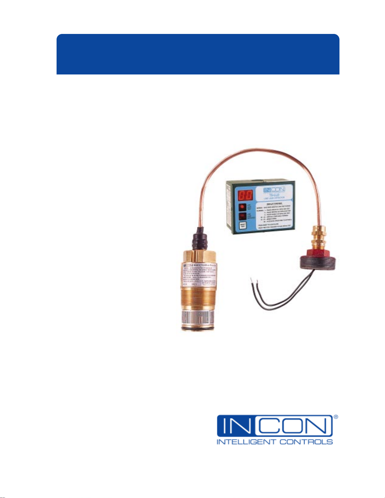
TS-LLD
Electronic Line Leak Detector
Installation Guide
Part Number: 000-1359, Rev. H
Copyright
TS-LLD INSTALLATION GUIDE
©
March 2012
Page 2
NOTICE
INCON has strived to produce the finest possible manual for you, and to ensure that the
information contained in it is complete and accurate. However, INCON makes no expressed or
implied warranty with regard to its contents. INCON assumes no liability for errors or omissions, or
for any damages, direct or consequential, that result from the use of this document or the
equipment which it describes.
This document contains proprietary information and is protected by copyright. All rights are
reserved. No part of this document may be reproduced in any form without the prior written
consent of INCON.
INCON reserves the right to change this document at any time without notice.
Need Help ? Contact INCON at:
INTELLIGENT CONTROLS, INC.
PO Box 638
SACO ME 04072
Office Hours: 8 a.m. to 5 p.m. EST Monday through Friday
Sales 24 hour Technical Service
Phone: (800) 872-3455 Phone: (800) 984-6266
Fax: (207) 283-0158 Fax: (207) 282-9002
E-mail: sales@intelcon.com E-mail: tech@intelcon.com
Visit our web site at: http://www.intelcon.com
INCON ® is a registered trademark of Intelligent Controls, Inc.
Tank Sentinel ® is a registered trademark of INCON
Red Jacket ® is a trademark of the Marley Pump Co.
FE Petro ® is a registered trademark of FE Petro, Inc.
The INCON TS-LLD is covered by United States Patent Number 5,918,268 (June 29, 1999)
Copyright 1995, 1996, 1997, 1998, 1999 Intelligent Controls, Inc. All rights reserved.
—
TS-LLD INSTALLATION GUIDE
❖
—
Page 3

Table of Contents
Chapter . Section Page No.
P Preface ................................................................................................. P - i
Graphic Symbol Conventions ................................................................................... P - i
Page Numbering Convention – Example: ........................................................ P - i
Page Layout Convention – Example: ................................................................ P - i
Components Included with Each TS-LLD System ................................................. P - ii
Before you Begin .................................................................................................... P - ii
NOTES ..................................................................................................... P - ii
1 TS-LLD Electronic Line Leak Detector – Overview .......................... 1 - 1
Overview and Theory of Operation.......................................................................... 1 - 1
Leak Test Requirements and Length ................................................................. 1 - 2
The LSU (Leak Sensing Unit) ............................................................................ 1 - 2
Communications ................................................................................................ 1 - 2
The Control Unit (CU) ........................................................................................ 1 - 3
Operator Interface ........................................................................................... 1 - 3
Your Notes ............................................................................................................ 1 - 4
2.0 TS-LLD Materials & Tools Required ............................................ 2.0 - 1
Do a Site Survey Before Attempting the Installation ............................................ 2.0 - 1
Submersible Turbine Pumps
Electrical Supply ........................................................................................... 2.0 - 1
Materials Required ............................................................................................... 2.0 - 1
Tools Required ..................................................................................................... 2.0 - 2
2.1 TS-LLD SAFETY............................................................................ 2.1 - 1
Important Safety Notes and Warnings................................................................. 2.1 - 1
Safety Notes and Warnings (continued... ) ...................................................... 2.1 - 2
2.2 TS-LLD LSU Installation ............................................................... 2.2 - 1
LSU Installation Steps ......................................................................................... 2.2 - 1
NOTE..................................................................................................... 2.2 - 4
NOTE..................................................................................................... 2.2 - 6
2.3 TS-LLD CU Installation & Wiring ................................................. 2.3 - 1
Control Unit ( CU ) Installation Steps ................................................................... 2.3 - 1
NOTE..................................................................................................... 2.3 - 1
TABLE 2.3 - 1 Typical Single Phase Wire Connection List ................. 2.3 - 4
NOTE..................................................................................................... 2.3 - 4
TS-LLD Line Leak Detector — Mechanical Blender Interface ............................ 2.3 - 8
Final Installation Steps .................................................................................... 2.3 - 14
TABLE OF CONTENTS Page TOC - 1 TOC
Page 4

Table of Contents
Chapter . Section Page No.
2.4OptionalTS-LLD – Tank Sentinel Console Interface............... 2.4 - 1
TS-1000 Tank Gauge Interface............................................................................ 2.4 - 1
Example TS-1000 & TS-2000 ATG Reports:.................................................... 2.4 - 2
TS-2000 Tank Gauge Interface............................................................................ 2.4 - 3
NOTE..................................................................................................... 2.4 - 3
Programming the TS-2000................................................................................ 2.4 - 4
Alarm Relays.................................................................................................. 2.4 - 4
Alarm Reports................................................................................................ 2.4 - 4
TS-1001 / TS-2001 LLDI Interface....................................................................... 2.4 - 4
Your Notes..........................................................................................................2.4 - 6
2.5TS-LLD After Installation Steps & Testing.................................. 2.5 - 1
After Installation Steps & Testing...................................................................... 2.5 - 1
Important — Warranty Registration..................................................................... 2.5 - 2
Important — Customer Documentation............................................................... 2.5 - 2
3TS-LLD System Operation & Testing................................................ 3 - 1
System Operation................................................................................................... 3 - 1
CU Component Location & Function................................................................... 3 - 2
Control Unit Display................................................................................................ 3 - 2
Normal Displays ( on steady / solid )................................................................... 3 - 2
Day Counts........................................................................................................ 3 - 2
Fault Displays ( Flashing on and off ).................................................................. 3 - 2
a. Line Leak Test Failure – Flashing Leak Alarm Codes.................................. 3 - 2
When a Leak Test Fails / Line Leak is Detected:.......................................... 3 - 3
b. Monthly-Compliance Warning – Flashing Day Codes.................................. 3 - 3
Indications:.................................................................................................... 3 - 3
Recommendation:......................................................................................... 3 - 3
c. Flashing Display Error Codes........................................................................ 3 - 3
Line Leak Test light................................................................................................. 3 - 4
Line Leak Detected light......................................................................................... 3 - 4
Display Functions, Codes & Concise Instructions.................................................. 3 - 4
Reset Test touch button — press to:....................................................................... 3 - 4
NOTE........................................................................................................ 3 - 4
Display Diagnostic Test Codes:......................................................................... 3 - 4
NOTE........................................................................................................ 3 - 4
TOC Page TOC-2 TS-LLD INSTALLATION GUIDE
Page 5

Table of Contents
Chapter . Section Page No.
3 TS-LLD System Operation & Testing (continued... )
Starting a 0.1 gph Annual Precision Leak Test ................................................ 3 - 4
Requirements: ............................................................................................... 3 - 4
Definition: quiet-time ..................................................................................... 3 - 4
How to Start a Manual Test ........................................................................... 3 - 5
Normal Operation – Sequence of Events / Steps ............................................... 3 - 5
1.) Product Dispense – Begin
( dispense: nozzle out / lever up / switch on ) ............................................. 3 - 5
2.) Product Dispense – End
( dispense: nozzle in / lever down / switch off ) ........................................... 3 - 5
3.) The 3.0 gph Gross Hourly Test .................................................................... 3 - 5
4.) The 0.2 gph Monthly-Compliance Test ........................................................ 3 - 5
NOTE........................................................................................................ 3 - 5
A 0.2 gph Test Automatically Starts When: ................................................... 3 - 6
Out of Compliance ............................................................................................ 3 - 6
Frequently Asked Questions:
Why do Days Count Up ?............................................................................... 3 - 7
Why do Error Codes 29, 30, 31, or 32 Appear ? ........................................... 3 - 7
How do I Display the Last Alarm or Error Code ? .......................................... 3 - 7
How do I Reset Flashing Error Codes ? ...How do I Allow Dispensing ?
...How do I Clear Flashing Codes ? ............................................................... 3 - 7
Why can’t I Reset and Dispense ?................................................................. 3 - 7
How Do I Verify a Leak ? ................................................................................ 3 - 7
How do I Start a Manual Test ? ...................................................................... 3 - 8
How Often Should the Manual Test be Run ? ............................................... 3 - 8
What Should I Do:
When a 3 gph Leak Test Fails / Gross Leak is Detected ? ............................ 3 - 8
When a 0.2 gph Leak Test Fails / Leak is Detected ? ................................... 3 - 8
When a 0.1 gph Annual Precision Leak Test Fails / Leak is Detected ? ....... 3 - 8
4 TS-LLD Line Leak Detection .............................................................. 4 - 1
When a Line Leak is Detected................................................................................ 4 - 1
NOTE........................................................................................................ 4 - 1
Steps to take When a Line Leak is Detected: ..................................................... 4 - 1
NOTE........................................................................................................ 4 - 2
How Often Should a Manual ).1 gph Test be Run ? ................................................ 4 - 2
Need help ? ....................................................................................................... 4 - 2
TABLE OF CONTENTS Page TOC - 3 TOC
Page 6

Table of Contents
Chapter . Section Page No.
5 TS-LLD Maintenance & Service ......................................................... 5 - 1
NOTE........................................................................................................ 5 - 1
Cleaning the Control Unit ........................................................................................ 5 - 1
Control Unit Replacement Parts ............................................................................. 5 - 1
Pump Relay Control Box Replacement Parts ......................................................... 5 - 1
Leak Sensing Unit (LSU) Adapters & Replacement Parts ..................................... 5 - 2
LSU Removal for Service / Inspection and Cleaning ........................................ 5 - 2
After Maintenance or Service DO – .................................................................. 5 - 2
6.0 Service & Factory Support .......................................................... 6.0 - 1
Where to Find Help .............................................................................................. 6.0 - 1
Service ................................................................................................................. 6.0 - 1
Need help ? Factory Support ............................................................................. 6.0 - 2
Phone and Pax members: ................................................................................ 6.0 - 2
Sales & Tech. Service numbers,
Technical Service & After Hours – Pager – ................................................ 6.0 - 2
INCON Office Hours ....................................................................................... 6.0 - 2
Before calling INCON ..................................................................................... 6.0 - 2
Return Shipments ................................................................................................ 6.0 - 2
Warranty Registration Form
Your Notes ......................................................................................................... 6.0 - 4
(copy, & Fax Reg. Form back to INCON) ....... 6.0 - 3
6.1 Test Fail Alarms, Warnings & Error Codes ................................ 6.1 - 1
Display Codes ..................................................................................................... 6.1 - 1
Normal Display Codes (on steady – not flashing)......................................... 6.1 - 1
Flashing Alarms, Warnings, and Errors Display Codes ............................... 6.1 - 1
Diagnostic Display Codes (on steady – not flashing) ................................... 6.1 - 1
Your Notes ......................................................................................................... 6.1 - 2
6.2 TS-LLD Troubleshooting Guide .................................................. 6.2 - 1
Display Codes ...................................................................................................... 6.2 - 1
Problem Description/Symptom
NOTE..................................................................................................... 6.2 - 2
Your Notes ......................................................................................................... 6.2 - 4
Probable Cause
(Action to take) ....... 6.2 - 1
6.3 TS-LLD Warranty & Terms ........................................................... 6.3 - 1
Warranty .............................................................................................................. 6.3 - 1
Warranty Disclaimer and Limitation of Liability ................................................... 6.3 - 1
For Further Information, Contact INCON ........................................................... 6.3 - 2
Your Notes ......................................................................................................... 6.3 - 2
TOC Page TOC - 4 TS-LLD INSTALLATION GUIDE
Page 7

Table of Contents
Chapter . Section Page No.
Appendix A TS-LLD Technical Specifications ......................................... A - 1
Operating Specifications ......................................................................................... A - 1
Electrical Specifications .......................................................................................... A - 1
Allowable Pipe Type and Length ............................................................................. A - 1
Environmental Specifications .................................................................................. A - 2
Mechanical Specifications ...................................................................................... A - 2
Safety Approvals and Listings ................................................................................ A - 2
User Feedback Form .......................................................................................... U - 1
Table of Figures & Diagrams
Chapter . Section Page No.
Chapter 1
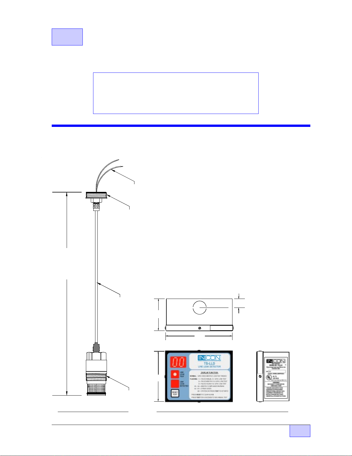
Figure 1.1 LSU Outline ...................................................................... 1 - 1
Figure 1.2 CU Outline Dimensions ...................................................... 1 - 1
Chapter 2 . Section 2
Figure 2.2-1 MI Cable Adapter Installation (before and after) ............ 2.2 - 1
Figure 2.2-2 Plug Location – RedJacket STP Housing ...................... 2.2 - 2
Figure 2.2-3 Plug Location – FE Petro STP Housing ......................... 2.2 - 3
Figure 2.2-4 TS-LLD Leak Sensing Unit – Thread Doping ................ 2.2 - 3
Figure 2.2-5 Line Leak Detector Installation – RedJacket Pump ....... 2.2 - 4
Figure 2.2-6 Line Leak Detector Installation – FE Petro Pump.......... 2.2 - 5
Figure 2.2-7 Line Leak Detector Wiring – RedJacket Pump .............. 2.2 - 6
Figure 2.2-8 Line Leak Detector Wiring – FE Petro Pump Housing... 2.2 - 7
Figure 2.2-9 MI Cable Adapter Installation – RedJacket Pump ......... 2.2 - 8
Figure 2.2-10 MI Cable Adapter Installation – FE Petro Pump ............ 2.2 - 9
Figure 2.2-11 Tightening MI Cable Adapter Fitting – RedJacket ....... 2.2 - 10
Figure 2.2-12 Tightening MI Cable Adapter Fitting – FE Petro .......... 2.2 - 11
Figure 2.2-13 Typical Installation TS-LLD Line Leak Detector ........... 2.2 - 12
Figure 2.2-14 INCON TS-LLD Installation @ Ext. Leak Det. Port ...... 2.2 - 13
Figure 2.2-15 INCON TS-LLD Installation at BigFlo
Diaphragm Valve ..................................... 2.2 -14 & 2.2 - 15
Figure 2.2-16 INCON TS-LLD Installation at FE Petro
STP or IST pumps (Single or Three Phase)............. 2.2 - 16
TABLE OF CONTENTS Page TOC - 5 TOC
Page 8

Table of Figures & Diagrams
Chapter . Section Page No.
Chapter 2 . Section 3
Figure 2.3-1 CU Internal & Bottom Views, and Relay Box Top View .. 2.3 - 1
Figure 2.3-2 CU Component Location - Internal View........................ 2.3 - 2
Figure 2.3-3 TS-LLD CU Typical Mounting and Conduit Routing....... 2.3 - 3
TABLE 2.3 -1 Typical Single Phase Wire Connection List .............. 2.3 - 4
Figure 2.3-4 Typical Single Phase 240 VAC
Pump Relay Box & Control Unit Wiring Diagram ........ 2.3 - 5
Figure 2.3-5 Typical Single Phase 240 VAC
Pump & Control Unit Interface Schematic .................. 2.3 - 6
Figure 2.3-6 Single Phase 240 VAC Multiple Pump & Manifolded
Line w/ Single LSU & CU Interface Schematic .......... 2.3 - 7
Figure 2.3-7 Mechanical Blender Dispensers to
TS-LLD Control Unit Interface Schematic .................. 2.3 - 8
Figure 2.3-8 Three Phase 240 VAC Pump & Control Unit
Interface Schematic .................................................... 2.3 - 9
Figure 2.3-9 Three Phase 240 VAC Supply – Starter – Motor
Control Box – and BigFlo Pump (3 wire)
Interface Schematic to TS-LLD ................................ 2.3 - 10
Figure 2.3-10 Three Phase 240 VAC Supply – Starter – Motor
Control Box – and BigFlo Pump (5 wire)
Interface Schematic to TS-LLD ................................ 2.3 - 11
Figure 2.3-11 Three Phase 240 VAC Supply – Starter & Motor
Control Box – Standard (FE Petro STP)
Interface Schematic to TS-LLD ................................ 2.3 - 12
Figure 2.3-12 Three Phase 240 VAC Supply – FE Petro
Variable Frequency Controller (VFC),
Motor Control Box – and IST Pump
Interface Schematic to TS-LLD ................................. 2.3 - 13
Figure 2.3-13 Control Unit Final Assembly ......................................... 2.3 - 14
Chapter 2 . Section 4
Figure 2.4-1 TS-1000 & TS-TGI Layout .............................................. 2.4 - 1
Figure 2.4-2 TS-1000 & TS-TGI – TS-LLD Wiring Diagram ............... 2.4 - 2
Figure 2.4-3 TS-2000 – TS-LLD Line Leak Detector Interface .......... 2.4 - 3
Figure 2.4-4 TS-1001 / 2001 Typical Hardware Layout ...................... 2.4 - 4
Figure 2.4-5 TS-1001 / 2001 LLD
I
Wiring Diagram ........................... 2.4 - 5
Chapter 3
Figure 3-1: Control Unit Cover – Component Location ....................... 3 - 2
Chapter 5
LSU Bottom & Side Views ........................................................................ 5 - 2
—
TOC Page TOC - 6 TS-LLD INSTALLATION GUIDE
❖
—
Page 9
P PREFACE
Contents:
Graphic Symbol Conventions (used in this manual)
Page Numbering and Layout Conventions
Components Included with Each TS-LLD System
Before You Begin
Graphic Symbol Conventions
NOTE
Important information, tips, and hints are highlighted by the NOTE graphic.
☞
CAUTION
graphic and contain instructions that must be followed to avoid faulty equipment
operation, or an explosion or shock hazards. If ignored, severe injury or death
result !
DANGER
instructions that must be followed to avoid an explosion or electrical shock
hazard. If ignored, severe injury or death
— ❖ — End of Chapter symbol
Page Numbering Convention – Example:
Page 4 – 1 = Chapter 4 page 1 and Page 6.1 – 2 = Chapter 6 . Section 1 – Page 2
Page Layout Convention – Example:
or
WARNING
messages are highlighted by the WARNING
messages are highlighted by the DANGER graphic and contain
will
result !
may
Chapter Number &
Name (
FIRST
Chapter Contents
TOP LEFT
PA GE
)
Manual Name
(
EVEN NUMBERED
PAGES
)
Page Number
Chapter Number
Chapter Name
ODD NUMBERED
(
PAGES
)
Page Number
Chapter Number
PREFACE Page P - i P
Page 10

Components Included with Each TS-LLD System
(TS-LLD Packing List)
(1) CU – Control Unit enclosure assembly (with stick-on CU Serial No. label)
(1) CU – Control Unit faceplate cover assembly
– (4) CU cover hold-down screws (4-40 x 1/4 inch)
*
(1) Bundle of different colored wire (Wire Bundle)
– (1) Spare 1/2 Micro Amp Fuse (F1)
*
– (1) Line Filter Capacitor, 1 µ Farad (for pump relay / motor control box)
*
(1) Sheet of (9) stick-on –
(1) LSU – Leak Sensing Unit (with stick-on LSU Serial No. label)
(1) Cable adapter (2 inch NPT) – (for Red Jacket Pumps)
– (1) Plug (1/4 inch NPT)
*
– (2) Wire Nuts (red) – (for connections at pump)
*
(1) Warranty Registration Card (write / stick-on CU & LSU Serial No. labels)
(1) TS-LLD Installation Guide Manual
(1) Read Me First – Installation Guide (Supplement Sheet)
(1) TS-LLD Quick Reference Guide (for the station owner / customer)
– Denotes parts in the supplied Hardware Kit (within plastic accessory bag)
*
DANGER
labels
Before you Begin
NOTES
☞
Refer to all applicable Local and State codes before beginning this installation. If a
conflict exists between the information presented in this manual, and the local
codes, then follow the local codes.
Maintenance, Service, and Installation of the TS-LLD system is to be performed by
Factory Trained and Certified personnel only.
Heed all
attempting any installation, maintenance, or service work.
This manual is your reference guide for the INCON TS-LLD line leak detector. It
includes typical installation details, which may vary depending on the actual
equipment at the site. Reference the Submerged Turbine Pump (STP) or
submersible pump, and pump relay (Motor Control) box — manufacturers’
documentation — for the installation details and requirements of this equipment.
CAUTIONS
and
WARNINGS
! See Chapter 2.1 about Safety, before
—
P Page P - ii TS-LLD INSTALLATION GUIDE
❖
—
Page 11
1 TS-LLD Electronic
Line Leak Detector system –
Overview
Contents:
• Overview and theory of
Operation
• Leak Test Requirements
and Length
Overview and Theory of Operation
- JU N C T IO N
BOX SIDE
8 INCH
LEADS
M I CABLE
ADAPTER
• The LSU (Leak Sensing Unit)
• Communications
• The CU (Control Unit)
• Operator Interface
The INCON TS-LLD is an electronic line leak detector
system. It has two components: a Control Unit (or CU)
and a Leak Sensing Unit (or LSU). The CU is mounted in
the station near the pump control relay box, and the LSU is
installed in the line leak detector port at the submersible
pump housing. One system per pump is required to detect
leaks from a pressurized fuel line.
2 3 .5 IN CH E S
APPROX.
OVERALL
LENGT H
ASSEMBLED
M I CABLE
The TS-LLD detects leaks in the pipeline leading from the
submersible pump to the dispenser. To comply with
current EPA regulations, three types tests are provided.
These are: a 0.1 gph annual test, a 0.2 gph monthly test,
and a 3.0 gph hourly test, which run at full line pressure.
Note: All Dimensions are in inches, and are approximate
0.60
2.25
Line #:
Product:
4.35
TOP & BOTTOM VIEW - C ONTROL UNIT (CU )
3.35
Knoc kout f or
1/2 inch f itting
- Ty pic a l -
x x x x x x x x
TS-LL D C U S eri al Numb er
xxxxxxxx
- LINE LEAK
P O RT S ID E
2 INCH NPT
FR ON T VIEW
RIGHT SIDE VIEW
Figure 1.1 LSU Outline Figure 1.2 CU Outline Dimensions
Overview Page 1 - 1 1
Page 12

Overview and Theory of Operation (Continued... )
The 0.1 gph annual test is started manually from the control unit (also known as a
manual test). On the other hand, the gross 3.0 gph hourly test and the
intermediate precision 0.2 gph monthly-compliance test both start and run
automatically.
and finish any line leak test.
Leak Test Requirements and Length
The 3.0 gph hourly test starts after every dispense and takes about 3 minutes
of
quiet-time
The 0.2 gph monthly-compliance test automatically starts after a 3.0 gph test
passes
hours. The monthly compliance test either runs, passes, and resets the day-count
to 00, or, advances a day if no test has passed after 24 hours. Depending on
conditions of the line and product, the 0.2 gph monthly-compliance test needs
13 minutes to 4 hours of
unless
Quiet-times, where no dispensing occurs, are required to start
to finish.
a previous 0.2 gph test has already passed within the last 24
quiet-time
to finish.
The manual 0.1 gph annual test needs 4 hours of
started, and takes about 13 minutes of
The LSU (Leak Sensing Unit)
The LSU (Leak Sensing Unit) has an O-Ring sealed valve at its base, which forces
all of the fuel flowing from the submersible pump through the LSU. A
microprocessor based printed circuit board is contained in the LSU. It uses a
proprietary technique to measure the actual product flow rate through a sensor
tube within the LSU, which can indicate a leak.
In most cases, the only required field wiring connections are two wires that are
connected in parallel to the existing Submersible Turbine Pump (STP) power-feedlines. A special copper sheathed, Mineral Insulated Cable (MI Cable) connects the
LSU to the electrical junction box at the pump discharge head.
Communications
The LSU not only receives power from the existing pump power-lines, but it
transmits data (communicates) over these lines. One of the power lines is routed
through a communications
pickup coil
quiet-time
quiet-time
inside the Control Unit (CU).
to finish after it starts.
before it’s
1 Page 1 - 2 TS-LLD INSTALLATION GUIDE
Page 13

The CU (Control Unit)
The CU monitors data that it receives from the pickup coil. The control unit
automatically turns on the pump when no one is dispensing product and calculates
accurate liquid flow rates to determine if a line leak exists or not.
The dispense signal is also monitored to identify when a customer is about to
dispense product. The CU is tied directly to the existing Pump Relay (Motor
Control) Box that is inside the station. The control unit activates the pump relay,
which turns the pump on and permits product dispensing when no line leak or
errors exist.
When a leak or error is detected, the pump relay is deactivated, which
keeps the pump turned off and prevents product dispensing.
Operator Interface
Two lights, a 2 digit display, and a reset-test touch button are provided for operator
interface. One light turns on when leak tests run, and the other flashes when a line
leak is detected. The two digit display shows operational status codes / day counts
(since the last monthly 0/2 gph line leak test passed), or flashes line leak alarms,
warnings, and error codes when and if they occur.
Brief operating instructions, and a list of codes and display functions are printed on
the control unit faceplate. See Chapter 3 for complete details.
Overview Page 1 - 3 1
Page 14

— Your Notes —
—
1 Page 1 - 4 TS-LLD INSTALLATION GUIDE
❖
—
Page 15
2.0 TS-LLD Materials & Tools
Required
Contents:
• Do a Site Survey Before Attempting the Installation
• Materials Required
• Tools Required
Do a Site Survey Before Attempting the Installation
Submersible Turbine Pumps:
What is the Motor Control / Pump Relay Box or Starter Type ? and
What is the Model Number, HP, Manufacturer, and age of all Turbine Pumps ?
Electrical Supply:
What is the Voltage and Phase (240 VAC – Single or Three Phase ? ) of all
Turbine Pumps ?
Materials Required
❒
Petroleum absorbent / absorbing rags
❒
Pipe Dope — Non-hardening (Soft-Set), UL Classified, gas/oil resistant —
to seal the Leak Sensing Unit, and the 1/4 inch Tank Test Port plug at the pump
❒
MI Cable Adapter — for installation on the TS-LLD Leak Sensing Unit (LSU). The
TS-RJ 2" NPT Cable Adapter for Red Jacket® submersible pumps is
with the TS-LLD),
Order INCON part number:
TS-FE 3" straight Cable Adapter for FE Petro® STPs
❒
Stick-on
❒
(1) 1/4 inch NPT pipe plug for the tank test port at the pump head
the TS-LLD)
❒
Red wire nuts for LSU wiring at the pump head
❒
(1) 1µ Farad Line Filter capacitor for the pump relay box
– supplied with the TS-LLD)
❒
Wire: 14 AWG, 3 feet
DANGER
(supplied
the adapter for FE Petro® STPs must be ordered separately...
*
labels
(INCON P/N 240-1175 – supplied with the TS-LLD)
(supplied with
(supplied with the TS-LLD)
(INCON P/N 020-0028
(supplied with the TS-LLD)
❒
(6) spade lugs for #8 studs to connect the 14 AWG wire at the pump relay box
Materials and Tools Required Page 2.0 - 1 2.0
Page 16

Materials Required
❒
(1) ring lug for the 14 AWG earth ground connection at the pump relay box
❒
(1) short 1/2 inch nipple — 2-1/2 to 3 inches long, or 1/2 inch 90 degree, and
hardware fittings to mount the CU to the relay box. (Or you may wall-mount the
control unit with appropriate fasteners, and use 1/2 inch EMT and fittings.)
❒
Steel stem Replacement Check Valve Kit (RedJacket P/N 144-184-5) to
*
replace older all plastic check valves – for older RedJacket pumps only
❒
Approved Pump Relay (Motor Control) Box – to comply with codes, retrofit
*
system to add a motor control box inside of the station
= Occasionally Required
*
❒
this Installation Manual – INCON P/N 000-1359 most current revision
❒
(1) Completed Warranty Registration Card –
❒
TS-LLD Quick Reference guide – INCON P/N 000-1447
TS-LLD).
station owner, shift managers / personnel
❒
Also, for use by the station owner, shift managers / personnel, provide the
name(s), phone number(s) of the local inspection agency and other applicable
information, instructions and regulations should a line leak be detected.
Leave all TS-LLD Quick Reference guide(s) on-site for use by the
(continued... )
(supplied with each TS-LLD)
(supplied with each
!
❒
Regulations and documentation: Applicable Local and State Codes, the
Manufacturers’ manuals and wiring diagrams of the — Dispenser, Submersible
Pump, and Relay Box (including other equipment not listed here and the sites’
electrical power distribution).
Tools Required
❒
Digital multimeter and test leads (high quality professional instrument)
❒
One each: wire strippers, cutters, and crimp splice tool
❒
Various sizes of flat and phillips bladed screwdrivers
❒
One 12 inch long adjustable wrench
❒
One 2 inch open end hex wrench
❒
Two 7/8 inch open end hex wrenches
❒
One socket set, extension, and square socket for a 1/4 inch NPT square headed
hole plug
—
2.0 Page 2.0 - 2 TS-LLD INSTALLATION GUIDE
❖
—
Page 17
2.1 TS-LLD SAFETY
Contents:
• Important Safety Notes and Warnings...
Read and follow these DANGER, WARNING, and CAUTION
messages before starting any installation or service.
Important Safety Notes and Warnings
DANGER
servicing, or working on this equipment, make sure you turn off all
submersible pump power (240 VAC) and pump relay coil /
dispenser power at the electrical panel. Tag, secure / lockout
these circuit breakers in the off position to prevent accidental or
unauthorized circuit breaker closure. Failure to turn off power
will result in severe injury or death !
DANGER
on, or wiring-to a circuit – a lethal electrical-shock-hazard could
exist, which would kill you.
in the on position, even when the circuit breaker lever is turned off.
DANGER
pump to run leak-tests at full line pressure between periods of
product dispensing (while the dispense switch is off). BEFORE
performing any installation or service (such as replacing fuelfilters) – turn off / lockout all electrical power sources to the
submersible pump(s), and relieve fuel-line pressure. Failure to
turn off power, and relieve fuel-line pressure before work is started,
may cause a pressurized fuel spill.
create a fire or explosion hazard that could result in injury or death.
Electrical Shock Hazard. Before installing,
Verify that no voltage exists before working-
Note: circuit breaker contact(s) can fail
The TS-LLD automatically starts the submersible
A pressurized fuel spill would
NOTE
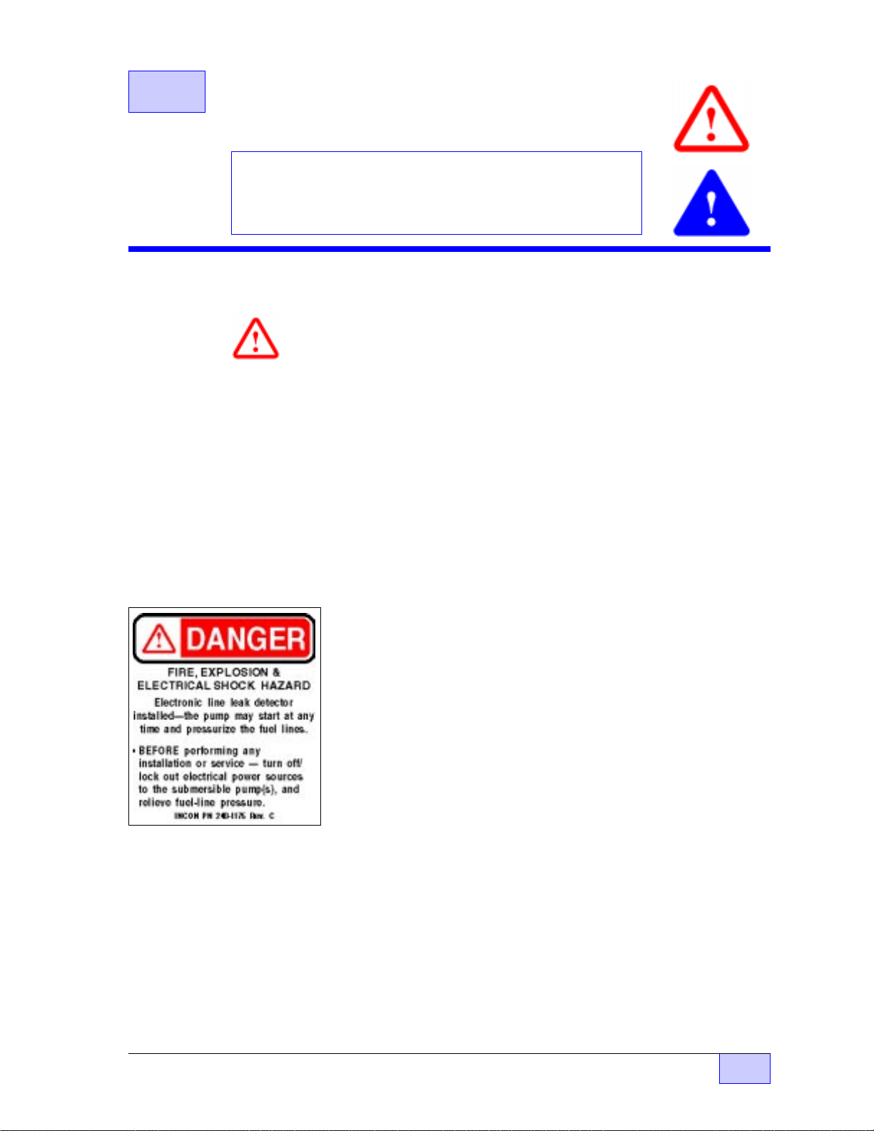
☞
INCON Danger stickers (see above left) are supplied with the
TS-LLD line leak detector. Apply these stickers on the pump relay
box cover, in locations near dispenser fuel-line filters, plugs,
emergency safety-shut-off valves, on the TS-LLD Leak Sensing
Unit (at the submersible pump housing), and other serviceable
components of a fuel line (where a spill would occur if the line
became pressurized). The selected surfaces must be clean, dry,
and in plain sight so that the warning can be read, and followed.
SAFETY Page 2.1 - 1 2.1
Page 18
Safety Notes and Warnings (continued... )
DANGER
After any installation or service of the submersible pump or its
housing, inspect the MI Cable at the LSU (Leak Sensing Unit) for
damage, twists, kinks, or breaks... 240 VAC power flows through
this cable to the LSU.
damaged, twisted, kinked, or broken.
this area could cause an explosion, injury or death.
WARNING
dispenser, may be under pressure. Turn off all pump power and
relieve pipeline pressure (reference and follow the pump
manufacturer’s directions about how to do this). If the line leak
detector/plug (or any other part of the submersible pump and fuel
line) is removed without first relieving pressure, then a product
leak will occur. This could cause an environmental, fire, or
explosion hazard, and may result in injury or death.
WARNING
fuel dispensing equipment (volatile fuel may be within the pump’s
leak detector port). Allow no source of combustion near the work
area. Failure to follow these directions may cause an explosion
hazard, which could result in property damage and death.
Explosion Hazard — Flammable Vapor Area.
DO NOT apply power if the MI Cable is
Electrical sparks or fire in
The fuel line from the submersible pump to the
Be careful not to cause sparks when working on
CAUTION
codes, the National Electric Code (NEC), and the Automotive and
Marine Service Station Code (NFPA 30A) before installation or
maintenance.
Refer to all applicable Federal, State and local
This installation is designed for submersible pumps
which have a pump relay box in the station.
does not exist, then the system must be retrofitted to add a
pump relay (motor control) box in the facility to comply with
Codes.
CAUTION
not recommend operating the LSU while submerged for long
periods of time (drain sump and manhole immediately).
2.1 Page 2.1 - 2 TS-LLD INSTALLATION GUIDE
Although the LSU is water resistant, INCON does
—
❖
—
If a pump relay box
Page 19
2.2 TS-LLD LSU Installation
Contents:
• LSU Installation Steps
(Typical in Pump Housing)
• Overall Site Installation Diagrams (typical Site,
in Angle Check Valve, RedJacket “BigFlo,” & FE
PETRO STP / IST pumps)
LSU Installation Steps
Follow the steps (below) in the order that they appear:
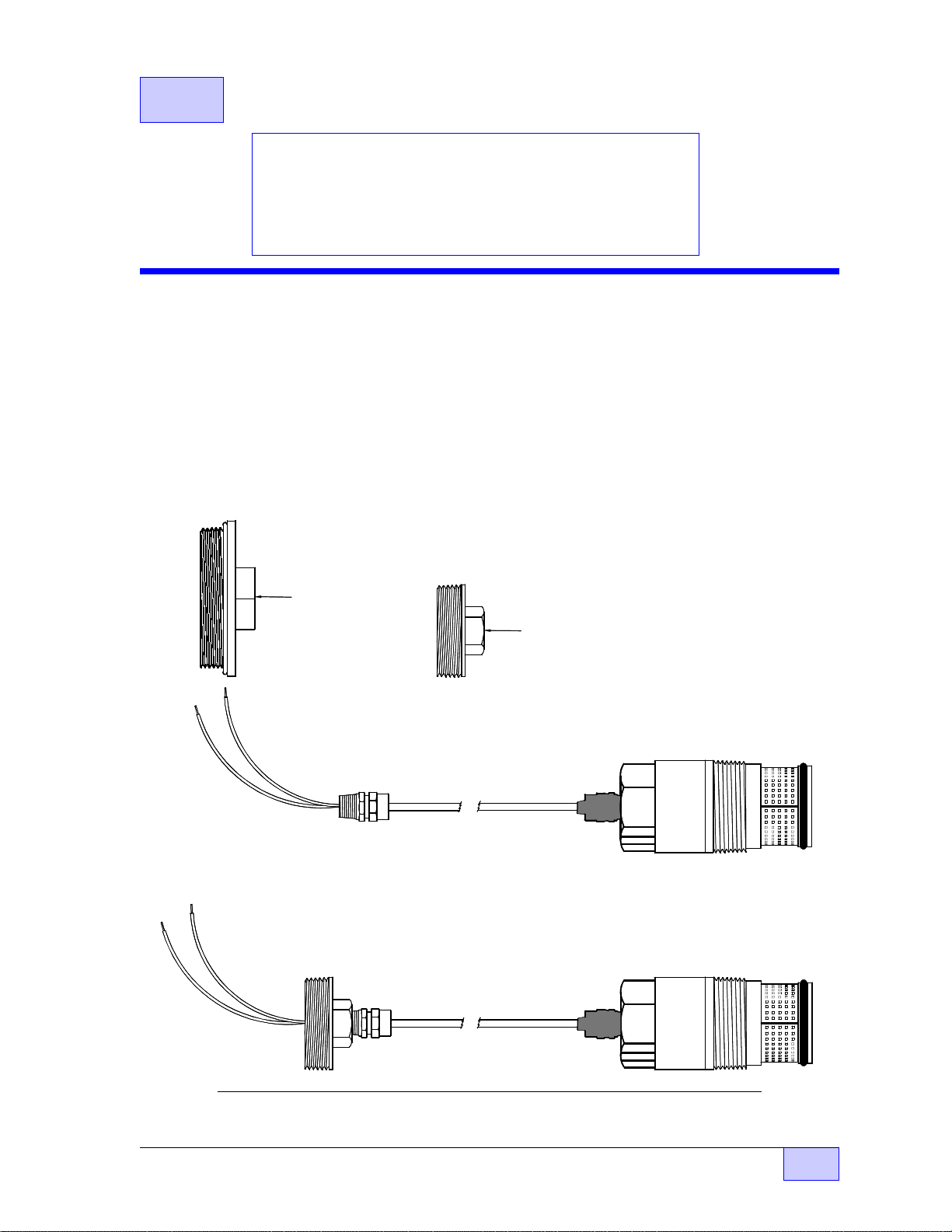
1) Install the appropriate size MI Cable Adapter on the LSU. Use an adjustable
wrench and a 7/8 inch wrench to tighten the MI cable adapter onto the TS-LLD as
shown in Figure 2.2-1. NOTE: The cable adapter that you install must match the
size of the junction box plug at the submersible pump housing (two different cable
adapters are shown in Figure 2.2-1). The 3 inch straight TS-FE cable adapter
must be ordered separately because the pump type and manufacturer varies.
TS- F E
3 INCH
M I CA BL E
ADAPTER
For FE Petro
Pumps
TS- RJ
2 INCH NPT
M I CA BL E
ADAPTER
For Red Jacket
Pumps
TS-LLD
LINE LEAK DETECTOR
LEAK SENSING UNIT
(LSU)
Figure 2.2-1 MI Cable Adapter Installation (before and after)
LSU Installation Page 2.2 - 1 2.2
Page 20
DANGER
Fire, Explosion, & Electrical Shock Hazard. Before installing,
servicing, or working on this equipment, make sure all submersible pump power
and pump relay coil / dispenser power is turned off & locked out at the electrical
panel.
lines, and electrical shocks.
Prevent automatic or unauthorized pump start-ups, spills from pressurized
See Chapter 2.1 follow all Safety advise.
2) Relieve pipe line pressure. Reference the detailed instructions found in the
submersible pump manufacturers’ documentation about relieving pressure in the
pipe line.
WARNING
The pipe line is under pressure – relieve line pressure. If the
line leak detector / plug is removed before the pipe line pressure is relieved, then a
product leak will occur ! A explosion, fire, or environmental hazard may be created.
3) Remove the 2 or 3 inch junction box plug and the 2 inch line leak plug, or
mechanical line leak detector (if present), from the pump housing per Figure 2.2-2
or 2.2-3. Use petroleum absorbent / absorbing rags to collect and contain spills if
they occur (be sure to properly dispose of these afterwards). If a mechanical line
leak detector was removed, then apply pipe dope on the threads of the
supplied 1/4 NPT hole plug, and install this plug into the tank test port.
MECHANICAL
2" PLUG
LINE LEAK
DETECTOR
2" PLUG
1/4" PLUG
STATION
CONDUIT
PUMP HOUSING
Figure 2.2-2 Plug Location – RedJacket® Submersible Pump Housing
PIPELINE
2.2 Page 2.2 - 2 TS-LLD INSTALLATION GUIDE
Page 21
3" PLUG
STATION
CONDUIT
PORT
PUMP HOUSING
1/4" PLUG
2" PLUG
PIPELINE
Figure 2.2-3 Plug Location – FE Petro Submersible Pump Housing
4) Apply Pipe dope to the line leak detector threads per Figure 2.2-4.
TS-LLD
LINE LEAK DETECTOR
LEAK SENSING UNIT
(LSU)
e
Pip
Dope
Pipe dope
only these
thre ads
Figure 2.2-4 TS-LLD Leak Sensing Unit – Thread Doping
LSU Installation Page 2.2 - 3 2.2
Page 22
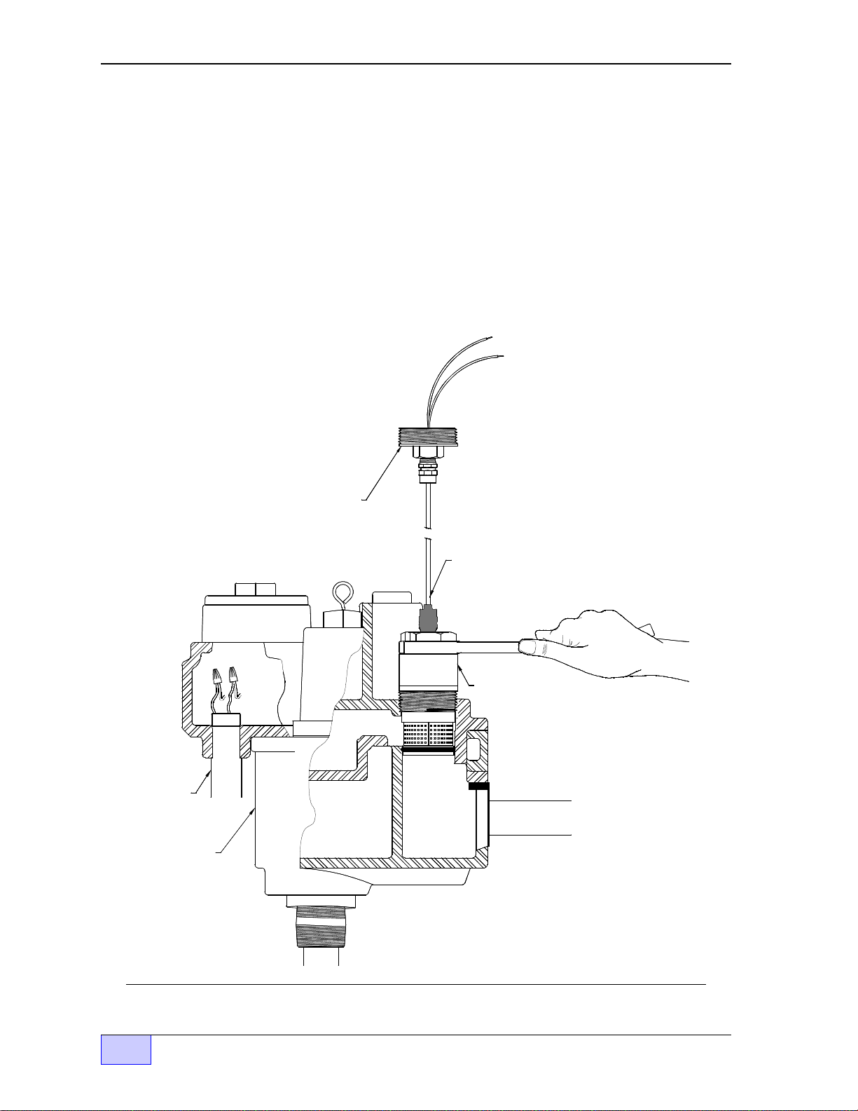
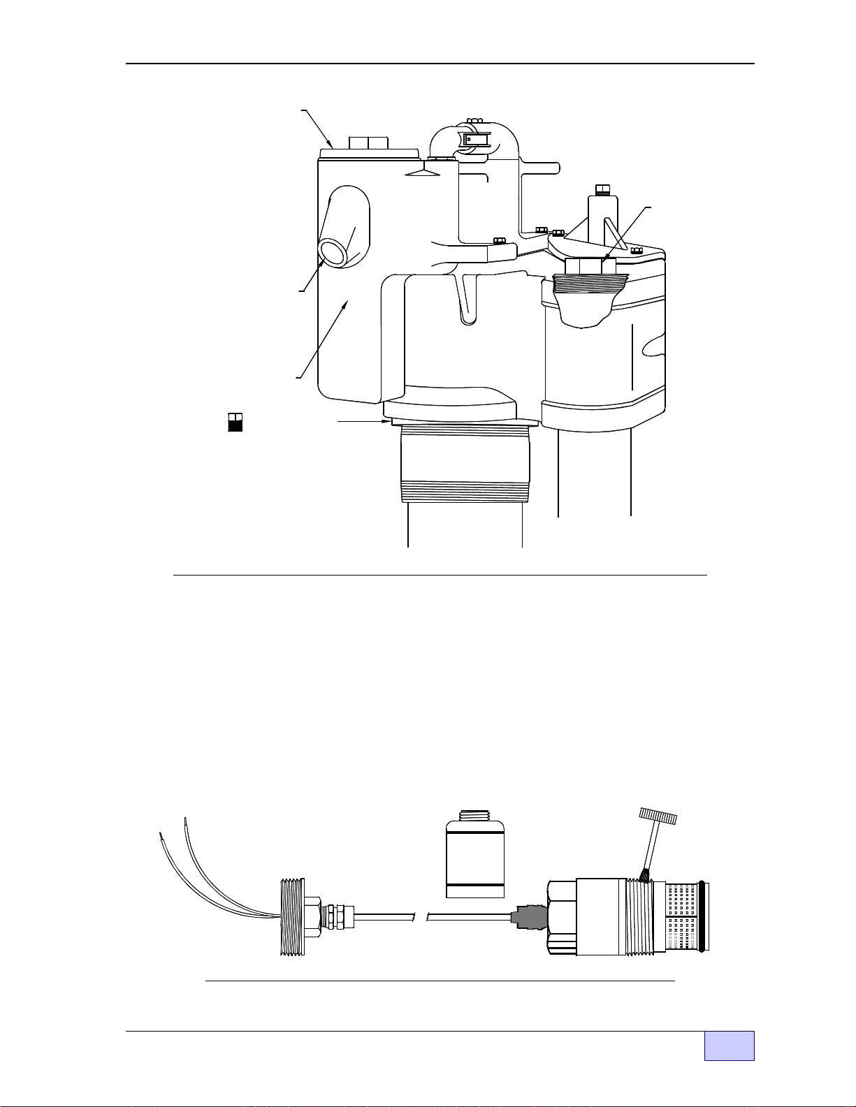
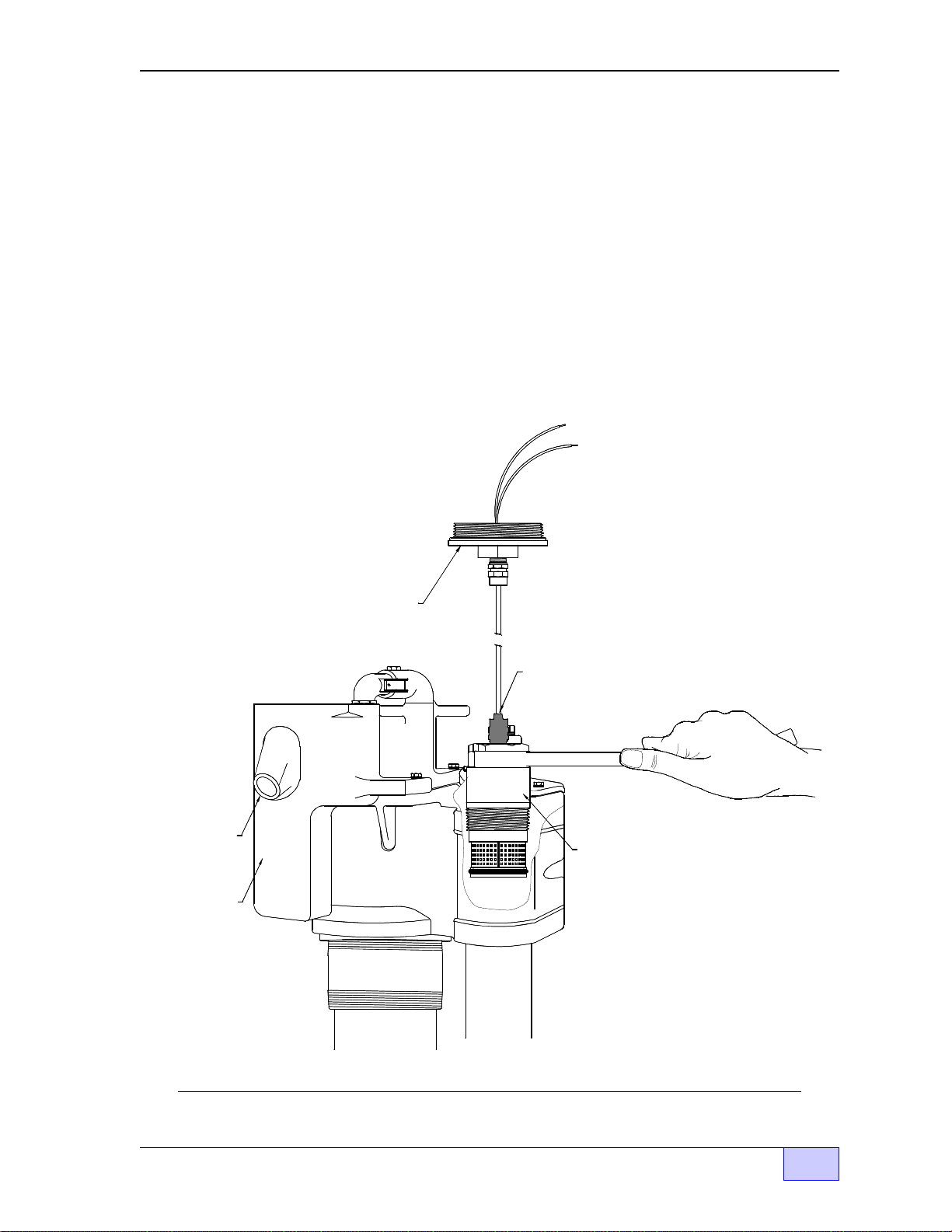
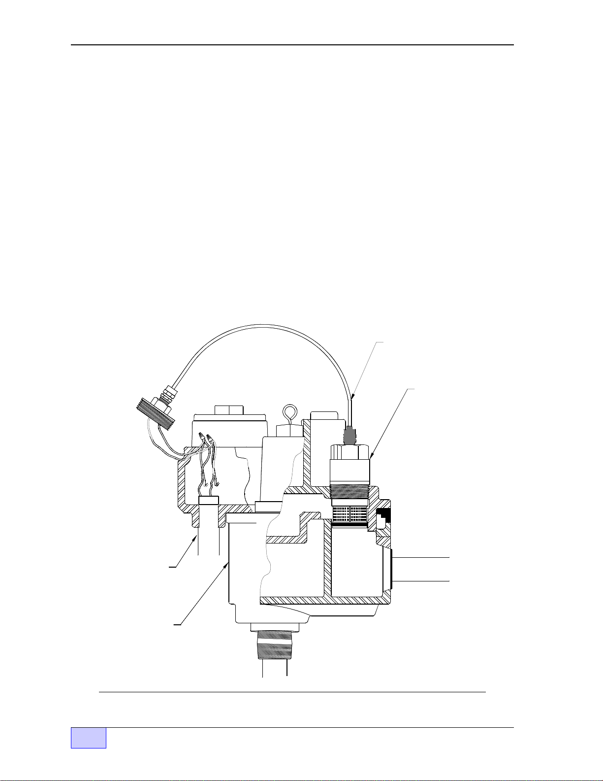
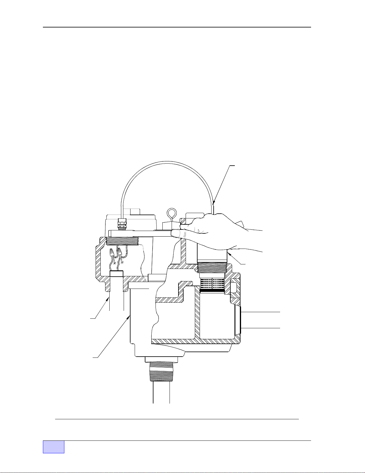
5) Insert the Leak Sensing Unit into the line leak port at the pump housing. See
Figure 2.2-5, or 2.2-6, and tighten the detector with a 2 inch hex – open end
wrench (no larger than 12" long to prevent overtightening and possible pump
housing damage or leaks). DO NOT overtighten the LSU in the pump head !
NOTE
☞
The MI Cable should be straight, vertical and able to rotate
freely with the LSU during the insertion or removal process.
M I CABLE
ADAPTER
M I CABLE
LINE LEAK
DETECTOR
STATION
CONDUIT
PIPELINE
PUMP
HOUS ING
Figure 2.2-5 Line Leak Detector Installation – RedJacket® Pump Housing
2.2 Page 2.2 - 4 TS-LLD INSTALLATION GUIDE
Page 23
STATION
CONDUIT
PORT
PUMP
HOUSING
M I CABLE
ADAPTER
MI CABLE
LINE LEAK
DETECTOR
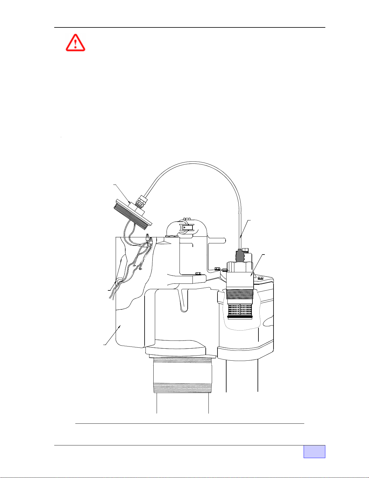
Figure 2.2-6 Line Leak Detector Installation – FE Petro Pump Housing
LSU Installation Page 2.2 - 5 2.2
Page 24
6) Carefully bend the thin-wall MI cable by hand and align the 2 or 3 inch cable
adapter fitting with the
hands when bending to fit. DO NOT force or bend the MI cable against the
compression fittings. Be sure you leave enough room to work (as shown in Figure
2.2-7, or 2.2-8).
junction box
plug opening. Support the MI cable with both
NOTE
☞
Avoid breaking the MI cable — DO NOT bend the MI cable too
close to the fittings. An LSU that has a damaged MI Cable is
unusable and must be replaced before power is applied.
7) Carefully remove each wirenut, one at a time and check each for the absence of
power (see Figure 2.2-7, or 2.2-8).
M I CABLE
LINE LEAK
DETECTOR
STATION
CONDUIT
PUMP
HOUSING
Figure 2.2-7 Line Leak Detector Wiring – RedJacket® Pump Housing
2.2 Page 2.2 - 6 TS-LLD INSTALLATION GUIDE
PIPELINE
Page 25
DANGER
Make sure you check these wires for the absence of power
before proceeding. All pump power (240 VAC) and pump relay / dispenser power
must be off before this installation is started, otherwise a lethal hazard will be
created which could kill you or others.
Note:
A circuit breaker contact(s) can
stick closed even when the circuit breaker is in the off position.
8) Leak Sensing Unit Wiring – Reference Figure 2.2-7, or 2.2-8.
a) Use one of the supplied red wire nuts, and twist one wire lead from pump
together with one of the black wire leads from the LSU.
b) Again use a red wire nut, and twist the remaining lead from pump together
with the remaining black wire lead from the LSU.
c)
For Canadian TS-LLD leak sensing units only:
connect the green (ground)
wire from the pump to the green LSU wire.
M I CABLE
ADAPTER
STATION
CONDUIT
PORT
PUMP
HOUSING
M I CABLE
LINE LEAK
DETECTOR
PIPELINE
Figure 2.2-8 Line Leak Detector Wiring – FE Petro Pump Housing
LSU Installation Page 2.2 - 7 2.2
Page 26
9) Stuff the wires back into the pump housing and carefully finish bending the MI
cable so that the cable adapter engages the threaded opening of the junction box.
Make sure to push the wires down enough to avoid pinching, or cutting through
the wire insulation from the cable adapter when it is tightened down.
Reference
Figure 2.2-9, or 2.2-10.
10) Tighten the MI cable adapter (new junction box cover) after making sure that
compression fitting is loose and is able to rotate freely — to prevent bending
and twisting damage to the MI Cable. Apply electrically conductive pipe dope to
the cover or the junction box. Use a 12 inch adjustable wrench. Reference Figure
2.2-9, or 2.2-10.
M I CAB LE
STATION
CONDUIT
PUMP
HOUSING
Figure 2.2-9 MI Cable Adapter Installation – RedJacket® Pump Housing
LINE LEAK
DETECTOR
PIPELINE
2.2 Page 2.2 - 8 TS-LLD INSTALLATION GUIDE
Page 27

M I CABLE
ADAPTER
STATION
CONDUIT
PORT
PUMP
HO USING
M I CABLE
LINE LEAK
DETECTOR
PIPELINE
Figure 2.2-10 MI Cable Adapter Installation – FE Petro Pump Housing
LSU Installation Page 2.2 - 9 2.2
Page 28

11) Tighten the MI cable compression fitting with a 7/8 inch wrench. Be careful
g
g
not to overtighten the compression fitting –
damage and failures
– torque to 25 lbs/ft. Reference Figure 2.2-11, or 2.2-12.
avoid MI cable twisting / bending
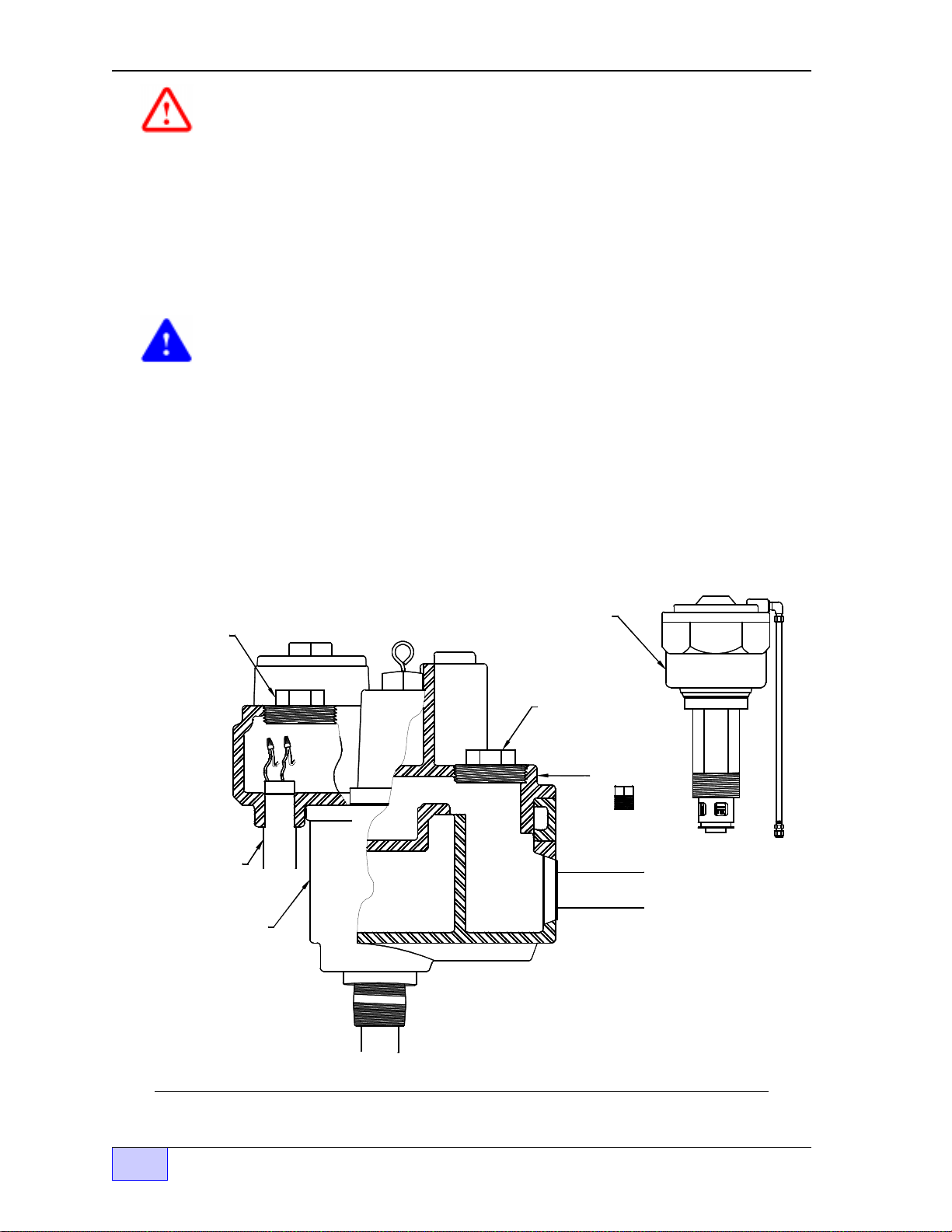
12) Recommended for Red Jacket installations: inspect and replace the check valve
under the functional element – IF – it doesn’t have a stainless steel stem. Use
Red Jacket replacement part number: 144-184-5.
13) Finally, inspect the MI Cable at the LSU (Leak Sensing Unit) for damage, twists,
kinks, or breaks —
replaced before power is applied.
M I Cable
Upper
Compression Fittin
Lower Junction Box /
Cable Adapter Fittin
DETAIL A
a LSU that has a damaged MI Cable is unusable and must be
Install a new LSU if the MI Cable is damaged.
Stainless
Steel
st em
Plastic
Check Valve
Detail
M I CABLE
STATION
CO NDUIT
PUMP
HO USING
PIPELINE
Figure 2.2-11 Tightening MI Cable Adapter Compression Fitting – RedJacket® Pump
2.2 Page 2.2 - 10 TS-LLD INSTALLATION GUIDE
Page 29

DETAIL A
g
g
DANGER
After any installation or service of the submersible pump or its
housing, inspect the MI Cable at the LSU (Leak Sensing Unit) for
damage, twists, kinks, or breaks... 240 VAC power flows through
this cable to the LSU.
damaged, twisted, kinked, or broken.
this area could cause an explosion, injury or death.
M I C ab le
Upper
Compression Fittin
Low er Junc tion Box /
Cable Adapter Fittin
Explosion Hazard — Flammable Vapor Area.
DO NOT apply power if the MI Cable is
Electrical sparks or fire in
M I CABLE
AD AP TE R
STATION
CONDUIT
PORT
PUMP
HOUSING
M I C AB LE
LINE LEAK
DETECTOR
PIPELINE
Figure 2.2-12 Tightening MI Cable Adapter Compression Fitting – FE Petro Pump
LSU Installation Page 2.2 - 11 2.2
Page 30

2.2 Page 2.2 - 12 TS-LLD INSTALLATION GUIDE
g
g
Reference Schematic Figure 2.3 - 8
Electrical
Power Panel
Pump
Relay
Boxes
INCON TS-LLD Line Leak Detector
Typical Installation in Leak Detector Port
TS-LLD CUs
(Control Units):
# 2 and # 1
2
1
TS-LLD LSU # 1
(Leak Sensing Unit # 1)
at submersible
pump housin
Dispenser
# A
Dispenser
TS-LLD LSU # 2
(Leak Sensing Unit # 2)
at submersible
pump housin
# X
NOTE:
NOTE:
A TS-TGI Tank Gauge Interface
A TS-TGI Tank Gauge Interface
module is required to connect
module is required to connect the
the TS-LLD Line Leak Detector
TS-LLD Line Leak Detector system
system to an INCON TS-1000
Tank Sentinel console.
to an INCON TS-1000 Tank Sentinel console. See the TS-TGI Install
See the TS-TGI Install Manual.
Manual.
For TS-1001/2001 Tank Sentinel
consoles, use the LLD /
...see the OPTIONAL TS-LLD TANK
SENTINEL ATG CONSOLE
INTERFACE chapter in this manual.
Existing
Conduit
(Pump 1)
Submerged
Turbine
Pump
Tank - Pump # 1
I
interface
Existing
Conduit
(Pump 2)
Figure 2.2-13 Typical Installation INCON TS-LLD Line Leak Detector
Epoxy
Filled
EYS
Seal
Fitting
Explosionproof
Junction
Box
Tank - Pump # 2
Page 31

LSU Installation Page 2.2 - 13 2.2
g
g
g
g
g
g
Reference Schematic Figure 2.3 - 8
Electrical
Power Panel
Pump
Relay
Boxes
INCON TS-LLD Line Leak Detector
External Leak Detector Port Installation
TS-LLD CUs
(Control Units):
# 2 and # 1
2
1
TS-LLD LSU (#1)
(Leak Sensin
at STP housin
Standard
Single Phase Installation
Dispenser
Unit)
# A
Dispenser
# X
TS-LLD LSU (#2)
(Leak Sensing Unit)
at External Leak Detector Port
NOTE:
A TS-TGI Tank Gauge Interface
module is required to connect the
TS-LLD Line Leak Detector system
to an INCON TS-1000 Tank Sentinel console. See the TS-TGI Install
Manual.
For TS-1001/2001 Tank Sentinel
consoles, use the LLD /
...see the OPTIONAL TS-LLD TANK
SENTINEL ATG CONSOLE
INTERFACE chapter in this manual.
Epoxy
Filled
Fittin
I
interface
Existin
Conduit
(Pump 2)
Existin
Conduit
(Pump 1)
Submer
Turbine
Pump (STP)
ed
("Standard" Single Phase
Tank - Pump # 1
Installation)
Figure 2.2-14 INCON TS-LLD Installation at External Leak Detector Port
EYS
Seal
Explosionproof
Junction
Boxes
Tank - Pump # 2
Installation within an
External Leak Detector Port
( not pump housing)
Page 32

2.2 Page 2.2 - 14 TS-LLD INSTALLATION GUIDE
g
g
y
y
g
g
g
y y
Electrical
Power Panel
Pump
Relay
Boxes
3 Phase
Pump
Motor
Starter
INCON TS-LLD Line Leak Detector
BigFlo & Diaphragm Valve Installation
TS-LLD CUs
(Control Units):
# 2 and # 1
2
1
Epoxy
Filled
2
EYS
Seal
TS-LLD LSU (#1)
(Leak Sensing Unit)
at pump housing
Standard Single
Phase Installation
Fittings
Dispenser
# A
Dispensers
TS-LLD LSU (#2)
# B thru # X
(Leak Sensing Unit)
at Diaphragm Valve
see Detail A - A
NOTE:
1)
An additional Sin
Rela
Control Box (panel), two additional
wires, and possibl
le Phase 230 VAC
an additional conduit run to
the LSU, are required for 3 Phase Applications.
The INCON TS-LLD LSU MUST be installed
2)
so the fasteners are ali
ned in a 12 & 6 o'clock
(vertical) position as shown in Detail A - A.
Tighten the LSU to meet this requirement.
Existing
Conduit
(Pump 2)
Submerged
Pump (STP)
Detail A - A
Overhead Top View
(correct ali
nment)
Partial
Enlar
ed
Side View
Existing
Conduit
(Pump 1)
Turbine
Tank - Pump # 1
("Standard" Sin
Installation)
le Phase
BigFlo Pump
(BigFlo Three Phase Pump and
Diaphragm Valve Installation)
BigFlo
STP
Pump
Explosionproof
Junction
Box . . . . .
Tank - Pump # 2
Note:
Use two
conduits
when
conduit
fill exceeds
40% full as
specified
b
our
National
Electric
Code.
Page 33

BIG-FLO PUMP & DIAPHRAGM VALVE
Reference Schematic Figures 2.3 - 9 & 10
Detail A
Installation (2 Explosion proof Conduit Outlet
Boxes & Hardware and 1 conduit run)
BIG-FLO PUMP & DIAPHRAGM VALVE
Detail B Alternate
Installation (2 Explosion proof Conduit Outlet
Boxes & Hardware and 2 conduit runs)
LSU Installation Page 2.2 - 15 2.2
3/4 inch
Conduit
& EYS
Epoxy filled
" Y " Seal
fitting
Crouse-Hinds:
GUAD
or GUAM
& GUJC
A
BigFlo
STP
Pump
UL approved
Explosion Proof
Junction Boxes
Class 1, Div's 1 & 2
Groups C, D
MI Cable
INCON
TS-LLD
A
Line Leak
Detector LSU
Diaphram
Valve
3/4 inch Conduit
& EYS Epoxy filled
" Y " Seal fittings
BigFlo
or
To / From
Pump Control
Relay Box &
3 Phase
Motor
Starter
Underground
Containment / Storage Tank
To Dispenser
Note: Use two conduits when conduit fill exceeds 40% full as specified by your National Electric Code.
Use recommended components or equivalent
To
Pump
Control
Relay
Box
From #
3 Phase
Motor
Starter
STP
Pump
Crouse-Hinds:
GUJC Explosionproof Junction Box
A 3/4 TO 1/2 inch
bushing is also
required for the
TS-LLD LSU fitting
A
A
Figure 2.2-15 INCON TS-LLD Installation at BigFlo Diaphragm Valve
Page 34

2.2 Page 2.2 - 16 TS-LLD INSTALLATION GUIDE
g
Reference Schematic Figures 2.3 - 11 & -12
❖
—
—
Electrical
Power Panel
Motor
Control
Panels
3 Phase
Starter
- or Variable
Frequency
NOTE:
An additional Single Phase 230 VAC
1)
Relay Control Box (panel), and two additional
wires for the LSU, are required for
Three Phase pump Applications.
Motor Control Panels may be either:
2)
Single Phase 230 VAC Relay Control Boxes,
- or - Single or Three Phase 230 VAC
Variable Frequency Controllers (VFCs).
Controller (VFC)
2
1
2
INCON TS-LLD Line Leak Detector
FE PETRO STP and IST (or STP-VS2 VFC)
Installation
TS-LLD CUs
(Control Units):
# 2 and # 1
TS-LLD LSU (#1)
(Leak Sensing Unit)
at STP housing
Existin
Conduit
(Pump 1)
Existing
Conduit
(Pump 2)
Submerged
Turbine
Pump (STP)
Dispenser
# A
TS-LLD LSU (#2)
(Leak Sensing Unit)
at IST pump housing
Epoxy
Filled
EYS
Seal
Fitting
Dispenser
# X
Explosionproof
Junction
Boxes
Tank - Pump # 1
( "Standard" STP Single Phase
Installation )
( FE PETRO Three Phase:
IST pump or STP Installation )
Figure 2.2-16 INCON TS-LLD Installation at FE PETRO STP or IST pumps
Single or Three Phase 240 VAC Applications
Tank - Pump # 2
Page 35

2.3 TS-LLD CU Installation & Wiring
Contents:
• Control Unit Installation Steps (Location, Product Configuration,
TS-2000 Configuration, Mounting the Control Unit, Relay Box &
Control Unit Wiring TABLE 2.3-1)
• Wiring Diagrams & Schematics (Pump Control Relay Box,
Single Phase 240 VAC, 3 Phase 240 VAC, 3 Phase RedJacket BigFlo,
3 Phase 240 VAC - FE Petro - STP & IST applications)
• Final Installation Steps
Control Unit ( CU ) Installation Steps
Follow the installation steps (below) and in the order that they appear:
NOTE
☞
DANGER
Electrical Shock Hazard. BEFORE installing, servicing or
working on this equipment, turn off all submersible pump power (240 VAC) and
pump relay coil / dispenser power at the electrical panel. Tag, secure / lockout
these circuit breakers in the off position to prevent accidental or unauthorized
circuit breaker closure. Failure to turn off power will result in severe injury or
death ! Check all wiring terminals for the absence of power before proceeding.
Note: Circuit breaker contact(s) can stick closed even when the circuit breaker
lever is in the off position.
You must know the dispense line number, product dispensed, and which pump
relay box (motor control box) is associated with this line.
1) Select an accessible mounting location for the control unit (see Figures 2.3-1 &
2.3-3), and remove the appropriate conduit knockouts. The CU is usually
mounted above the pump relay box (shown here)... other locations are possible.
1 485A
INTERNAL VIEW
UP
TB 2
TB 1
2 485B
3 DSY1
4 DSY2
5 ALAR M
1 110V
2 NEU
3 P-OUT
4 P-IN
SIG RTN
F1
KNOCKOUT S FOR ELECTRICAL FIT TINGS
TOP VIEW SHOWN
CU ENCLO SURE
BOTTOM VIEW
REM O V E
KNOCKOUT
FOR 1/2 INCH
ELECTRICAL
FITTING
AT BOT TOM
Figure 2.3-1 CU Internal & Bottom Views, and Relay Box Top View
Control Unit Installation Page 2.3 - 1 2.3
Page 36

BOX
UP
Printed Circuit
Board
(P C B o a rd )
TS-LLD CO NTRO L UNIT (CU) ENCLOSURE
1 485A
2 485B
TB 2
3 DSY1
4 DSY2
Donut shaped
Pic ku p Coil
TB 1
5 ALARM
1 110V
2 NEU
3 P-O UT
4 P-IN
SIG RTN
F1
COVER (SHIELD ON)
P L AS TIC S H IEL D SH O W N
MOUNTED OVER PC BOARD.
R E M O VE TH E S H IEL D TO SE T
THE JUMPER LINK POSITION
AS S H OW N BE L O W .
TH IS S H IE L D M U S T B E
IN PLACE BEFORE TH E
COVER IS RE-INSTALLED.
GREEN C ONNEC TOR (J1)
= 1/4 inch hole
lo c a tio n s fo r
w a ll mounting.
Alternate
Jum per
Link Position:
for Diesel, or
Fuel Oils
DIESEL
1
GAS
Standard
Jum per
L i n k P o si ti o n s:
for Gas olin e
DIESEL
J2
Standa rd TGI
Interface
Alternate
Jum per
Link Position:
for Gas olin e
DIESEL
for
TS-2000 Interface
Jumper Link
Side V ie w
Standa rd TGI
Interface
Alternate
Jum per
Link Position:
for Diesel, or
Fuel Oils
DIESEL
for
TS-2000 Interface
2
GAS
Figure 2.3-2 CU Component Location - Internal View
Control Unit Installation Steps (continued... )
GAS
J2
GAS
J2J2
3
GREEN C ONNEC TOR (J1)
J1
J2
DIESEL
C ontrol Unit cover
COVER (SHIELD OFF)
GAS
PC BOARD
S h ie ld
Bottom View
2) Product Configuration (Top Jumper Link) — required only for Diesel, Fuel Oil,
or Kerosene — skip this step if gasoline will be monitored. Remove the plastic
shield in back of the control unit cover. Pull up and reposition the top blue jumperlink at J2, so that it is installed over the left two pins. See Figure 2.3-2 and
reinstall the plastic shield when done.
3) INCON TS-2000 Configuration (Bottom Jumper Link) — this step is required
only when the TS-LLD will be wired to or interfaced to an INCON model TS-2000
ATG console. Remove the plastic shield from the control unit cover. At J2, pull up
and reposition the bottom jumper-link so that its installed over the left two pins.
See Figure 2.3-2 and the applicable INCON Application Note about wiring to
a TS-2000. Reinstall the plastic shield when done.
2.3 Page 2.3 - 2 TS-LLD INSTALLATION GUIDE
Page 37

(
p
p
p
(es)
g
NIPPLE
PUMP RELAY BOX
WARNING: DISCONNECT POWER
BEFORE REMOVING COVER
To 208/230 VAC
single phase
Power Source
electr ical power
anel) - circui t
breakers
90° FITTING
PUMP RELAY BOX
WARNING: DISCONNECT POWER
BEFORE REMOVING COVER
- - Al ter nate Mounti n
To Di s
Switch
enser
To Submersibl e
Pump explosion
roof Junction Box
WALL
MOU N TED
& EMT
PUMP RELAY BOX
WARNING: DISCONNECT POWER
BEFORE REMOVING COVER
- - Alternate Mounti ng B - -
WARNING Avoid electrical shock hazards. Disconnect all electrical power
source s BEFORE removing any enclosure cover !
NOTE: Ground equipment as required by your local and National Electric Codes.
A - -
Figure 2.3-3 TS-LLD CU Typical Mounting and Conduit Routing
NOTE
☞
4) Mount the CU to the pump relay box (see Figure 2.3-3 above for typical
mounting methods). You may mount the control unit to a wall through the two 1/4
inch mounting holes — use fasteners that are appropriate for the wall
construction. The centers of these holes are shown on the inside label of the
control unit. In addition, make sure that the UP arrow is pointing up as shown in
Figure 2.3-2.
Control Unit Installation Page 2.3 - 3 2.3
Page 38

Control Unit Installation Steps (continued...
}
5) Wiring at the Pump Control Relay Box:
a) Remove the wire from S2 to the relay coil
b) Remove the wire from M2 to the relay N.O. contact
c) Install the 1µ Farad “Line Filter” capacitor (INCON P/N 020-0028) between
terminals L1 and L2
d) Wire the CU to the pump relay box as described below TABLE 2.3-1 and as
shown in Figures 2.3-4 & 2.3-5. Strip 1/4 inch of insulation off each end (for
termination at the control unit and for the spade crimp connectors at the pump
relay box). Use connectors sized for 14 AWG wire.
NOTE
☞
Other pump relay boxes may have different terminations, and/or may
be wired differently than what is shown in this manual.
Typical Single Phase Wire Connection List TABLE 2.3 -1
PUMP RELAY BOX — to — TS-LLD CONTROL UNIT ( CU )
)
From
L2 BLK 14 AWG (supplied) 110 V (AC Line Power input) TB1 - 1
N WHT 14 AWG (supplied) Neu (Line Power Neutral) TB1 - 2
Relay Coil RED 14 AWG (supplied) P-OUT (Pump On - output signal, TB1 - 3
S2 BRN 14 AWG (supplied) P-IN (Pump On - input signal, TB1 - 4
M2
Relay N.O.
Ground Stud GRN 14 AWG (supplied) GND (Equipment Ground) Ground Stud
Wire
Color
ORG 14 AWG (supplied) 240 VAC (Pump Motor Power) { see below }
Wire Gauge Circuit (Description) To
110 V AC, to Pump Relay Coil)
{ Pump Motor Power - the 14 gauge
orange wire is pre-routed through the
N O T E -
N O T E -
pick-up coil at the Control Unit.
relay box
terminal, & wire the other end to the
pump relay N.O. contact (Figure 2.3-
4)... no wiring/connection at CU
{ Ground according to
, wire one end to the M2
your
National Electric Codes.
At the
Local and
- N O T E
- N O T E
NOTE
☞
Electricians: All AC wiring at the control unit (TB1-1 110V and TB1-4 P-IN)
must be in-phase and read 0 VAC in respect to each other and must read
from 110 to 130 VAC in respect to ground. Reference Figures 2.3-4 thru
2.3-10. These are “typical” diagrams and may not represent the actual wiring.
A 0 VAC potential must exist from TB1-1 to the hot side of dispenser on switch S1
( or to S2 ) with the dispense switch on. Take voltage readings at the pump relay
box. Use the leg that is in-phase with S1 ( L1 or L2 that reads 0 VAC) and wire it
to TB1-1 ( 110V ). For 3 phase applications — DO NOT use any leg that
reads more than 130 VAC to Ground
!
2.3 Page 2.3 - 4 TS-LLD INSTALLATION GUIDE
Page 39

g
g
g
No termination - wire runs through
the d onut-s hap e d P ic kup Coil
Figure 2.3-4 Typical Single Phase 240 VAC Pump Relay Box & Control Unit
RLY N.O. CONTACT (ORG)
Pickup Coil
M2 (ORG)
TS-LLD Control Unit
1 485A
2 485B
3 DSY1
4 DSY2
5 ALARM
F1
TB2
Control Unit Installation Page 2.3 - 5 2.3
Wiring Diagram
Remove wires
(shown as
dashed lines)
NO TE : Only the
new wirin
that's required
within the
Pump Relay
Box, is shown
in this d ia
ram .
Pump Relay Box
PUMP RELAY
- - COM - -
- - - COIL - - -
N.O.
S1 M2S2 M1 N L2L1
RLY COIL (RED)
GROUND
STUD/SCREW
L2 (BLK)
N (WHT)
1 110V
2 NEU
3 P-OUT
S2 (BRN)
GROUND
(GRN)
#8-32 Ground S tud
4 P-IN
SIG RTN
Install the 1uF Line Filter
Capacitor (INCON PN 020-0028)
Be tween L1 & L2
DANGER Electrical shock hazards!
Turn off and lock-out the submersible
pump power source (terminated at
L1 and L2), and the pump relay power
source (terminated at S2, from the
dispenser switch) BEFORE workin
on this equipment. Failure to turn off
these power sources will result in
severe injury or death.
TB1
Page 40

L1
Reference Site Layout
Figures 2.2 - 13 & 14
L2
From: 208/230 Volt, Single Phase,
Electrical Power Source
Neutral Bus
LINE
LOAD
COM
N.O.
L1
COM
N.O.
M1
Remove
Original
Wiring
BLK
TS-LLD Leak
Sensing Unit
(Installed at
the pump
housing.)
L2
M2
BLK
ON
OFF
Line Filter Cap
(See Note 1)
Dispenser
Switch
(or switches)
GROUND
208/230 Volt, Single Phase,
Electrical Power Panel
3 Pole Switched-Neutral
Circuit Breaker
N
COIL
S2S1
115 V.
No connection
at CU -- wire is
run through the
donut-shaped
Pickup Coil
RLY N.O. Contact
M2 (ORG)
L2 (BLK)
N (WHT)
RLY COIL (RED)
S2 (BRN)
GROUND (GRN)
Remove
Original
Wiring
208/230 Volt, Single Phase Submersible Pump Motor
Relay Box
TS-LLD Control Unit
(use bottom, 1/2 inch
conduit knockout)
Pickup Coil
F1
#8-32 Ground Stud
1 485A
2 485B
3 DSY1
4 DSY2
5 ALARM
1 110V
2 NEU
3 P-OUT
4 P-IN
SIG RTN
TB2
TB1
NOTES:
Single Phase
OL
DANGER ELECTRICAL SHOCK HAZARDS. TURN OFF AND LOCK-OUT THE
SUBMERSIBLE PUMP POWER SOURCE, AND THE PUMP RELAY POWER SOURCE
AT THE CIRCUIT BREAKER - BEFORE - WORKING ON THIS EQUIPMENT. FAILURE
TO TURN OFF THESE POWER SOURCES WILL RESULT IN SEVERE INJURY OR DEATH.
Submersible
Pump Motor
with
Thermal
Overload
MI Cable
Adapter
(cover) for
Explosion
Proof
junction box
1) Install the 1uF Line Filter Capacitor (INCON
PN 020-0028) between input AC line terminals at
the Relay Box.
2) The TS-LLD is installed at the submersible pump
housing (see Chapter 2.2 for details).
3) Follow your local and National Electrical Codes
for electrical grounding requirements.
4) If three phase is available, see Figure 2.3-6.
2.3 Page 2.3 - 6 TS-LLD INSTALLATION GUIDE
Figure 2.3-5 Typical Single Phase 240 VAC Pump & Control Unit
Interface Schematic
Page 41

g
g
1 110V
2 NEU
TB1
4 P-IN
3 P-OUT
TB2
1 485A
3 DSY1
2 485B
5 ALARM
4 DSY2
F1
Power Source = L1
TS-LLD Control Unit (CU)
ram
SIG RTN
Dia
NOTES
GND
No connection.
Wire is routed
through the
donut-shaped
Pickup Coil
Pickup Coil
RLY N.O. (ORG)
GND
N
Neutral (WHT)
M1 (ORG)
L1 Line (BLK)
RLY COIL (RED)
Dispense ( BRN)
Pump On Sig.
1) The Leak Sensing Unit (LSU) is installed at STP # 1
2) In line check valves are required at the output of
each RedJacket Submerged Turbine Pump
3) All ancillary pumps must be controlled / enabled
by the Aux. Relay Box as shown.
4) Only STP #1 Runs during line leak tests
DANGER ELECTRICAL SHOCK HAZARDS. TURN OFF AND LOCK-OUT THE
SUBMERSIBLE PUMP POWER SOURCE AT THE CIRCUIT BREAKER - BEFORE -
WORKING ON THIS EQUIPMENT. FAILURE TO TURN OFF PUMP & DISPENSER
POWER SOURCE WILL RESULT IN SEVERE INJURY OR DEATH.
GND
N
M2
L1 L2 S2 S1
M1
L2 S2 S1
L1
Aux. Relay Box
N
GND
Dispense
Switch(es)
M2
M1
Relay Box # 2
Pump Control
GND
(dashed lines)
N
Remove Wires
Conduit
to pump
Junction
Box
STP # 2 Motor
OL
INCON TS-LLD - 1 LSU Multiple Pumps & Manifolded Lines - Wirin
Electrical
Power
Panel
L1 L2
L1 L2 S1S2
P/N
020-0028
Cap at L1 and L2
M1 M2
Install Line Filter
STP #1 Motor & LSU
TS-LLD LSU
at Leak Detection Port:
STP # 1 Pump Housing
(remove dashed wires)
Relay Box # 1
Pump Control
Figure 2.3-6 Single Phase 240 VAC Multiple Pump & Manifolded Line with Single LSU & CU
Interface Schematic
Control Unit Installation Page 2.3 - 7 2.3
Page 42

TS-LLD Line Leak Detector —
g
g
g
Mechanical Blender Interface
When connecting a TS-LLD line leak detector to systems with mechanical
blenders, tie the: premium, all mid-grades, and regular dispenser switch signals
together (electric blenders can be wired normally). Wire both premium and
regular TS-LLD Control Units at TB1-4 (P-IN). See the typical (partial) wiring
diagram below. Because the mid-grades are blended mixtures of the premium
and regular octanes, any product dispense will abort leak tests at the premium
and regular Control Units.
CAUTION
The
dispense on
signals must be
in phase
to avoid electrical shorts
and damage. Verify that all dispenser switch signals are in phase before you tie
them together (in phase = 0 Volts AC in respect to each other and 120 Volts AC in
respect to Neutral or ground). Note that both pumps will be active on any
dispense.
F1
F1
1 485A
2 485B
3 DSY1
4 DSY2
5 ALARM
1 110V
2 NEU
SIG RTN
1 485A
2 485B
3 DSY1
4 DSY2
5 ALARM
1 110V
2 NEU
SIG RTN
S1
C
N.O.
PREMIUM
Dispense
Switch (es)
S1
C
N.O.
MID-GRADE
Dispense
Switch (es)
S1
C
N.O.
REGULAR
Dispense
Switch (es)
Dispense
(on) si
(on) signal
(on) si
nal
Dispense
Dispense
nal
TB2 -
PREMIUM
TS-LLD
Control Unit
TO: PREMIUM MOTOR
START RELAY COIL
Tie
to
ether
TB2 -
REGULAR
TS-LLD
Control Unit
TO: REGULAR MOTOR
START RELAY COIL
TB1 -
TB1 -
Figure 2.3-7 Blended Dispensers to TS-LLD Control Unit – Interface Schematic
2.3 Page 2.3 - 8 TS-LLD INSTALLATION GUIDE
Page 43

L1 ( or L3)
Reference Site Layout
Figures 2.2 - 13 & 14
See
Note
L2
From: 208/230 Volt, Three Phase, Electrical Power Source,
utilizing two lines to power a Single Phase load.
(See Note 1)
1
Neutral Bus
LINE
LOAD
COM
N.O.
See
Note
1
L1
(or L3)
COM
N.O.
Remove
Original
Wiring
BLK
TS-LLD Leak
Sensing Unit
(Installed at
the pump
housing.)
L2
M2M1
BLK
ON
OFF
Line Filter Cap
(See Note 2)
Dispenser
Switch
(or switches)
GROUND
OL
MI Cable
Adapter
(cover) for
Explosion
Proof
junction box
DANGER ELECTRICAL SHOCK HAZARDS. TURN OFF AND LOCK-OUT THE
SUBMERSIBLE PUMP POWER SOURCE, AND THE PUMP RELAY POWER SOURCE
AT THE CIRCUIT BREAKER - BEFORE - WORKING ON THIS EQUIPMENT. FAILURE
TO TURN OFF THESE POWER SOURCES WILL RESULT IN SEVERE INJURY OR DEATH.
208/230 Volt, Single Phase,
Electrical Power Panel
3 Pole Switched-Neutral
Circuit Breaker
N
COIL
Remove
Original
Wiring
Single Phase
Submersible
Pump Motor
with
Thermal
Overload
115 V.
S2S1
NOTES:
1) Only use phases L1 & L2, or L3 & L2. DO NOT use
phase L1 & L3.
2) Install the 1uF Line Filter Capacitor (INCON PN 020-0028)
between AC input line terminals at the Relay Box.
3) The TS-LLD is installed at the submersible pump housing
(see Chapter 2.2 for details).
4) Follow your local and National Electrical Codes for
electrical grounding requirements.
5) 230 VAC must not enter the Control Unit! All Control Unit
AC wiring must be 110 volts (110V power = TB 1-1, dispenser
switch [ S2 ] on signal = TB 1-4, and pickup coil [ M2 ] sense
lead all must be derived from the same phase [ L2 ] ).
208/230 Volt, Single Phase Submersible Pump Motor
Relay Box
No connection
at CU -- wire is
run through the
donut-shaped
Pickup Coil
RLY N.O. Contact
Pickup Coil
M2 (ORG)
L2 (BLK)
N (WHT)
RLY COIL (RED)
S2 (BRN)
GROUND (GRN)
TS-LLD Control Unit
(use bottom, 1/2 inch
conduit knockout)
1 485A
2 485B
3 DSY1
4 DSY2
5 ALARM
F1
1 110V
2 NEU
3 P-OUT
4 P-IN
SIG RTN
#8-32 Ground Stud
TB2
TB1
Figure 2.3-8 Three Phase 240 VAC Supply – Single Phase 240 VAC Pump & Control Unit
Interface Schematic
Control Unit Installation Page 2.3 - 9 2.3
Page 44

Reference Site Layout Figure 2.2 - 15
N
N
GND
TB2
1 485A
5 ALARM
4 DSY2
2 485B
3 DSY1
F1
Power Source = L1
TS-LLD Control Unit (CU)
Pickup Coil
No connection.
Run wire
L1 and L2)
Cap (between
Install Line Filter
RLY N.O. (ORG)
through the
donut-shaped
Pickup Coil
L2
P/N
020-0028
L1
N
2 NEU
1 110V
Neutral (WHT)
L1 Line (BLK)
M1 (ORG)
TB1
4 P-IN
3 P-OUT
SIG RTN
GND
S2 (BRN)
Pump On Sig.
(L1 is source)
RLY COIL (RED)
NOTES
1) If the motor starter coil is 230 VAC then do not wire to neutral --
wire to M1.
2) Observe color code L1 L2 L3 phase sequence for proper rotation
of motor.
3) All conduit fittings, EYS seal fittings, and junction boxes in
manholes or other Hazardous areas are to be explosionproof
rated for: Class 1, Div 1, Group D and wet locations
DANGER ELECTRICAL SHOCK HAZARDS. TURN OFF AND LOCK-OUT THE
SUBMERSIBLE PUMP POWER SOURCE (L1, L2, L3 - AT THE CIRCUIT
BREAKER) - BEFORE - WORKING ON THIS EQUIPMENT. FAILURE TO TURN
OFF THE THREE PHASE POWER SOURCE WILL RESULT IN SEVERE INJURY
OR DEATH.
INCON TS-LLD & RedJacket Big Flo Three Phase Wiring Diagram
for newer 3 wire Three Phase motors
BLK
TS-LLD
LSU (Leak
Sensing Unit)
at diaphragm
valve
BLK
N
GND
Electrical
Power
Panel
L3
L2L1
Aux.
Control
Relay
M2S2S1 M1
Box
(remove
dashed
wires)
N (N o t e 1)
L2L1 L3
Dispense
Switch
Separate
wires
must be
run.
T2T1 T3
RED
ORG
Three Phase BigFlo
Three
Phase
Motor
Starter
(ref.
Note 1)
STP...newer 3 wire version...
Overloads (OLs) in series w/ T1 & T3
Figure 2.3-9 Three Phase 240 VAC Supply – Starter – Motor Control Box – and BigFlo Pump
(3 wire) Interface Schematic to TS-LLD
2.3 Page 2.3 - 10 TS-LLD INSTALLATION GUIDE
Page 45

Reference Site Layout Figure 2.2 - 15
g
g
GND
TB2
1 485A
3 DSY1
2 485B
4 DSY2
5 ALARM
F1
Power Source = L1
TS-LLD Control Unit (CU)
h the
No connection.
Run wire
throu
P/N
020-0028
L1 and L2)
Cap (between
Install Line Filter
Pickup Coil
RLY N.O. (ORG)
donut-shaped
Pickup Coil
L2
L1
N
2 NEU
1 110V
Neutral (WHT)
L1 Line (BLK)
M1 (ORG)
TB1
4 P-IN
3 P-OUT
SIG RTN
GND
.
RLY COIL (RED)
S2 (BRN)
Pump On Si
See Note 5
NOTES
1) If the motor starter coil is 230 VAC then do not wire to neutral --
wire to M1.
2) Observe color code L1 L2 L3 phase sequence for proper rotation
of motor.
3) All conduit fittings, EYS seal fittings, and junction boxes in
manholes or other Hazardous areas are to be explosionproof
rated for: Class 1, Div 1, Group D and wet locations
DANGER ELECTRICAL SHOCK HAZARDS. TURN OFF AND LOCK-OUT THE
SUBMERSIBLE PUMP POWER SOURCE (L1, L2, L3 - AT THE CIRCUIT
BREAKER) - BEFORE - WORKING ON THIS EQUIPMENT. FAILURE TO TURN
OFF THE THREE PHASE POWER SOURCE WILL RESULT IN SEVERE INJURY
OR DEATH.
INCON TS-LLD & RedJacket Big Flo Three Phase Wiring Diagram
for older 5 wire Three Phase motors
BLK
N
Electrical
Power
Figure 2.3-10 Three Phase 240 VAC Supply – Starter – Motor Control Box – and BigFlo Pump
GND
Panel
TS-LLD
LSU (Leak
Sensing Unit)
at diaphragm
valve
S1 S2 M2 M1
Dispense
Switch
N (N o t e 1)
Motor
Starter
(ref.
Note 1)
Separate
wires
must be
run.
T2T1 T3
RED
ORG
BLK
L1 L2 L3
Aux.
Control
Relay
Box
(remove
dashed
L2L1 L3
Three
wires)
Phase
(5 wire) Interface Schematic to TS-LLD
Control Unit Installation Page 2.3 - 11 2.3
OL
Three Phase BigFlo
STP... older version
with separately wired
internal OverLoads ( OLs )
Page 46

Reference Site Layout Figure 2.2 - 16
g
g
m
g
g
GND
ra
P/N
020-0028
Install Line Filter
Cap at L1 and L2
(remove dashed wires)
Aux. Control Relay Box
N
GND
2 485B
3 DSY1F14 DSY2
1 485A
TB2
5 ALARM
2 NEU
1 110V
TB1
3 P-OUT
Power Source = L1
TS-LLD Control Unit (CU)
No connection.
Wire is routed
through the
donut-shaped
Pickup Coil
L1
NL2
M1
M2
S2
S1
Pickup Coil
RLY N.O. (ORG)
Neutral (WHT)
L1 Line (BLK)
M1 (ORG)
RLY COIL (RED)
N (N o t e 1)
4 P-IN
SIG RTN
GND
S2 (BRN)
Pump On Sig.
(source = L1)
Dispense
GND
N
Switches
Dia
s, and junction boxes in
NOTES
s, EYS seal fittin
1) If the motor starter coil is 230 VAC then do not wire to neutral --
wire to M1.
2) Observe color code L1 L2 L3 phase sequence for proper rotation
of motor.
3) All conduit fittin
manholes or other Hazardous areas are to be explosionproof
rated for: Class 1, Div 1, Group D and wet locations
DANGER ELECTRICAL SHOCK HAZARDS. TURN OFF AND LOCK-OUT THE
SUBMERSIBLE PUMP POWER SOURCE (L1, L2, L3 - AT THE CIRCUIT
BREAKER) - BEFORE - WORKING ON THIS EQUIPMENT. FAILURE TO TURN
BLK
TS-LLD
LSU (Leak
Sensing Unit)
at IST Pump
Housing
GND
Conduit to pump Junction Box
ORG
INCON TS-LLD & FE PETRO Three Phase STP Wirin
OFF THE THREE PHASE POWER SOURCE WILL RESULT IN SEVERE INJURY
OR DEATH.
Leak
Detection
Port
Electrical
Power
Panel
Figure 2.3-11 Three Phase 240 VAC Supply – Starter – and Motor Control Box
2.3 Page 2.3 - 12 TS-LLD INSTALLATION GUIDE
L2L1 L3
T2T1 T3
L1 L2 L3
Three
Phase
Motor
Control
Panel
Starter
...see
NOTES
1 and 2
Standard Interface Schematic to TS-LLD
BLK
RED
( OLs )
...OverLoads
STP 3 phase Motor
are in series with M1and M3
Page 47

Reference Site Layout Figure 2.2 - 16
GND
No connection.
Wire is routed
P/N
020-0028
Install Line Filter
Cap at L1 and L2
2 NEU
1 110V
TB1
4 P-IN
3 P-OUT
SIG RTN
TB2
2 485B
3 DSY1
1 485A
4 DSY2F15 ALARM
Power Source = L1
TS-LLD Control Unit (CU)
through the
donut-shaped
Pickup Coil
L1
Pickup Coil
RLY N.O. (ORG)
Neutral (WHT)
L1 Line (BLK)
M1 (ORG)
GND
RLY COIL (RED)
S2 (BRN)
Pump On Sig.
See Note 5
NOTES
1) Observe color code L1 L2 L3 phase sequence for proper rotation
of motor.
2) All conduit fittings, EYS seal fittings, and junction boxes in
manholes or other Hazardous areas are to be explosionproof
rated for: Class 1, Div 1, Group D and wet locations
INCON TS-LLD & FE PETRO IST (or STPs with VS2 suffix)
DANGER ELECTRICAL SHOCK HAZARDS. TURN OFF AND LOCK-OUT THE
SUBMERSIBLE PUMP POWER SOURCE (L1, L2, L3 - AT THE CIRCUIT
BREAKER) - BEFORE - WORKING ON THIS EQUIPMENT. FAILURE TO TURN
OFF THE THREE PHASE POWER SOURCE WILL RESULT IN SEVERE INJURY
OR DEATH.
Three Phase or Single Phase Wiring Diagram
BLK
TS-LLD
LSU (Leak
Sensing Unit)
at IST Pump
Conduit to pump Junction Box
Red
BLK
ORG
pump motor
(remove dashed wires)
Aux. Control Relay Box
N
GND
Electrical
Power
Panel
L3 L2 L1
M1
S2 M2 NL2
S1
GND
N
L3 L2 L1
Dispense
Switches
N
HOOK
Signal)
(Dispense
GND
M3 M2 M1
FE PETRO IST three phase
L3 is
optional
Three
Phase
wiring
Variable
Frequency
Controller
(VFC)
Figure 2.3-12 Three Phase 240 VAC Supply – FE PETRO Variable Frequency Controller,
Motor Control Box – and IST Pump Interface Schematic to TS-LLD
Housing
Leak Detection
Port
Overloads (OLs)
are in series w/ M1 & M3 )
Control Unit Installation Page 2.3 - 13 2.3
Page 48

Use a
perm anent
ink m a rk ing
pen and
write the
Line #
Product:
on the
labe ls b e low .
For Exam ple
1
Lin e # :
Gas
Product:
CU TOP VI EW
INTERNAL VIEW
UP
LLD # 1
Lin e # 1
G asoline
CU RI GHT SIDE VI EW
x x x x x x x x
TS-LLD CU Serial N umber
Line #:
1
Pr oduct:
G as
1 485A
2 485B
TB2
3 DSY1
4 DSY2
5 ALARM
1 110V
2 NE U
TB1
3 P -OUT
4 P-IN
SIG R TN
Final Installation Steps
6) Recheck your wiring. Make sure all terminations
are correct and tight.
7) Use a permanent ink marking pen to: write the
Line # and the Product being monitored on two
x x x x x x x
CU labels — The label inside of the control unit,
and the label located on the top right of the cover
label (so the box and cover can be reinstalled as a
matched-set). See Figure 2.3-6 to the left.
8) Reinstall the correct CU cover on the box – as
CU Serial
Num ber
a matched-set. See Figure 2.3-6 to the left.
9) Reinstall the pump relay box cover. See
Figures 2.3-1 & 2.3-3.
10) Nine INCON Danger stickers are supplied with
each line leak detector (P/N 240-1175). Apply
one sticker: on the pump relay box cover, in
locations near dispenser fuel-line filters, plugs,
emergency safety-shut-off valves, on the TS-LLD
Leak Sensing Unit, and onto other serviceable
components of a fuel line (where a spill would
occur if the line became pressurized). The
F1
selected surfaces must be clean, dry, and in plain
sight so that the warning can be read and followed.
Finally, see the next few Sections of this Chapter
about Optional Tank Gauge Console Interface and
the After Installation Steps / Testing.
KNOCKO UT
FOR 1/ 2 I NCH
ELECTRICAL
FITTING
AT T OP &
CU ENCLO SURE
TO P VI EW
Shield
BOTTOM
Line #:
Pr oduct:
Figure 2.3-13 Control Unit
Final Assembly
—
❖
—
2.3 Page 2.3 - 14 TS-LLD INSTALLATION GUIDE
Page 49

2.4 Optional TS-LLD –
Tank Sentinel ATG Console
Interface
Contents:
• TS-1000 TS-TGI Interface
• TS-2000 Interface
• TS-1001 / TS-2001 LLDI Interface
TS-1000 Tank Gauge Interface
The TS-LLD can be interfaced to an INCON TS-1000 console with the addition of
a TS-TGI module. The TGI module (Tank Gauge Interface module) can interface
up to 4 TS-LLD systems with the TS-1000.
methods covered in this Section have not been evaluated by Underwriters
Laboratories and are not considered part of this Listing.
NOTE – The devices and installation
For Installation, Programming, and Testing issues of the TS-LLD & TS-1000 tank
gauge console see the INCON, TS-TGI Installation Guide, manual P/N 000-1051.
EFI
Figure 2.4-1 TS-1000 & TS-TGI Hardware Layout (Motor Control Boxes not shown)
TS-LLD – Tank Sentinel ATG Console Interface Page 2.4 - 1 2.4
Page 50

TS-TGI
g
Field
Wirin
Diagram
240-1196
Rev. A
TS-TGI
CHANNEL 1 to CU / LINE # 1
wiring shown typical
Use: Shielded Pair, 20AWG Cable
1 485A
2 485B
TB2
3 DSY1
4 DSY2
- DC
to TB1SIG RTN
+ DC to
TB2- 5
(ALARM)
Shield
to TB1SIG RTN
TB1
5 ALARM
1 110V
2 NEU
3 P-OUT
4 P-IN
TS-TGI
with cover off
F1
SIG RTN
(4) #8-32
MOUNTING
SCREWS
TS-KB
1 485A
2 485B
TB2
3 DSY1
4 DSY2
5 ALARM
UP
TS-LLD Control Unit
(CU) / LINE # N
with cover off
F1
1 110V
2 NEU
TB1
3 P-OUT
4 P-IN
SIG RTN
TS-1000 Internal View
( with door open )
Figure 2.4-2 TS-1000 – TS-TGI Module – TS-LLD Control Unit Wiring Diagram
4 line report header (standard)
6/20/1999 09:05 AM
LINE TEST REPORT
Example
TS-1000 &
4 line report header (standard)
6/23/1999 10:08 AM
ACTIVE ALARM REPORT
(Not with TS-2000)
TS-2000 ATG
Reports:
INCON ENVIRONMENTAL
74 INDUSTRIAL PARK RD
SACO ME
SITE # 00001
4 line report header (standard)
6/23/1999 09:45 AM
ALARM REPORT
6/23/1999 09:45 AM
3 GPH LINE LEAK
LINE NO. 1
LOW BRI 6
ACTIVE
3 GPH LINE LEAK
LINE NO. 1
4 line report header (standard)
6/31/1999 11:01 AM
ALARM HISTORY REPORT
6/19/1999 03:45 PM
POWER UP
6/23/1999 09:45 AM
3 GPH LINE LEAK
LINE NO. 1
6/29/1999 10:14 AM
.2 GPH LINE LEAK
LINE NO. 4
TEST TIME 04:32 PM
TEST DATE 6/19/1999
TEST RESULT PASSED
4 line report header (standard)
6/23/1999 10:12 AM
LINE TEST HISTORY
TEST TIME 04:32 PM
TEST DATE 6/19/1999
TEST RESULT PASSED
TEST TIME 08:19 PM
TEST DATE 6/20/1999
TEST RESULT PASSED
TEST TIME 09:45 AM
TEST DATE 6/23/1999
TEST RESULT FAILED
LINE 1
LINE 1
2.4 Page 2.4 - 2 TS-LLD INSTALLATION GUIDE
Page 51

(J1)
g
g
TS-2000 Tank Gauge Interface
Remove the TS-LLD control unit cover & plastic shield, and reposition the blue
jumper links as shown in the diagram below. Do this when wiring to the discrete
input terminals of an INCON model TS-2000 ATG.
NOTE
TS-LLD Alarm Output ratings (from TB2-5) are:
+ 5 VDC, 60 milliAmps max. (resistive loads)
☞
INCON TS-2000 AUTOMATIC TANK GAUGE:
Discrete Input Interface terminals
for the TS-LLD Line Leak Detector
INPUT 4
{ spare 2 }
1
3
{ spare 1 }
INPUT 3
Use:
INPUT 1 for Line 1
INPUT 2 for Line 2
INPUT 3 for Line 3
INPUT 4 for Line 4
Collector transistor with a 270 ohm resistor tied to an internal + 5 V DC supply.
2
4
INPUT 2
{ leaktest }
5
7
{ setup }
INPUT 1
J5
J5-Even
6
8
Numbered
Terminals
DC Input
Discrete
Input Si
(GND)
J5-Odd
Numbered
Terminals
nal
RED
BLK
— the output is from an Open
INCON TS-LLD Line Leak Detector
- Control Unit
2 Pulses = Passed 0.2 GPH Test
3 Pulses = Failed 0.2 GPH Test
Activated = Failed 3.0 GPH Test
One Pulse = + 5 vdc
On 1 second and Off 1 second
TB2-5
TB1SIG RTN
ENCLOSURE
UP
1 485A
2 485B
TB2
3 DSY1
4 DSY2
TB1
5 ALARM
1 110V
2 NEU
3 P-OUT
4 P-IN
SIG RTN
F1
Green Connector
REPOSITION
JUMPER
LINKS
Alternate
Jumper
Link Position:
for Diesel, or
Fuel Oils
DIESEL
GAS
J2
for
TS-2000 Interface
Plastic shield is mounted
over the PC board
Remove the shield to set the
jumper link to the correct
position as shown below
(replace the shield before
reinstallin
the cover).
Alternate
Jumper
Link Position:
for Gasoline
DIESEL
GAS
J2
for
TS-2000 Interface
COVER (SHIELD OFF)
J1
Factory Default
Jumper
Link Positions:
DIESEL
GAS
J2
PC BOARD
DIESEL
for Gasoline
GAS
J2
Standard TGI
(TS-1000) Interface
COVER (SHIELD ON)
Figure 2.4-3 TS-2000 – TS-LLD Line Leak Detector Interface
TS-LLD – Tank Sentinel ATG Console Interface Page 2.4 - 3 2.4
Page 52

Programming the TS-2000
g
g
Alarm Relays
From ALARM RELAYS setup menu, select YES for LN LEAK RY1 to activate the
audible alarm inside of the console should a line leak occur. Select YES for LN
LEAK RY2 to control an external device that is wired to these contacts.
Alarm Reports
From SYSTEM setup menu, enable Report Alarms to have alarm reports printout
automatically at the console report printer. As with the TS-1000, Line Test
Reports and Line Test History Reports can be printed using the report key (see
previeous page for examples).
TS-1001 / TS-2001
The Line Leak Detector Interface to these console uses a 4 conductor, 22 AWG,
communications grade cable for the RS-485 protocol. See Figures 2.4-4 and
2.4-5 for additional details.
Communications Wirin
240 AC POWER WIRING Trou
LLDI
Interface
or
Trough Only
h Only
See the TS-1001 / TS-2001 Setup
Programming Guide (P/N 000-1053)
for programming details and available
reports.
Many line-related reports can be
printed at the console by using the
report key. See the TS-1001 /
TS-2001 Sample Reports Document
(P/N 000-1394) for Line – Test,
Diagnostic, and History Reports.
Also, in the sample reports document,
see Line Alarm Reports for active line
alarms, cleared line alarms, or line
alarm history reports.
Motor Control Panels
( Relay Boxes - or - Starters )
Figure 2.4-4 TS-1001 / TS-2001 LLDI Typical Connecting Hardware Layout
2.4 Page 2.4 - 4 TS-LLD INSTALLATION GUIDE
Page 53

)
TS-LLDI ( Line Leak Detector Interface )
W A R N I N G: AVOID ELECTRICAL SHOCK HAZARDS.
EXTERNAL POWER SOUCES MAY BE PRESENT LOCATE AND DISCONNECT ALL EXTERNAL POWER
SOURCES BEFORE WIRING OR SERVICING
THESE CIRCUITS.
Enlarged View of
Terminal Strip # J13
TB2-1 (485A)
TB2-2 (485B)
TB2-3 (DSY 1)
TB1-SIG RTN
Enlarged View
TS-LLD Control Unit (CU)
Interface Terminals:
1 485A
2 485B
TB2
3 DSY1
4 DSY2
5 ALARM
TS-LLD Control Unit (CU) box
UP
GND
F1
TB1
4 P-IN
SIG RTN
NOTE:
1)
CAUTION
installation: Read and reference the TS-LLD Manual
about Safety, and CU Installation (and wiring steps).
WARNING
2)
Turn off and disconnect all power to the pumps and
dispensers before wiring at the TS-LLD Control Units.
3) Up to four TS-LLD Control Units ( CUs ) can be
interfaced to the TS-1001 console and up to eight CUs
can be interfaced to the TS-2001 console.
BEFORE
attempting this
Avoid electrical shock hazards —
TB2
TB1
CU #1
CU #2
1 485A
2 485B
3 DSY1
4 DSY2
5 ALARM
1 110V
2 NEU
3 P-OUT
4 P-IN
SIG RTN
TS-LLD CU cover (back view)
THIS SHIELD MUST BE
IN PLACE BEFORE THE
F1
COVER IS RE-INSTALLED.
GREEN CONNECTOR (J1
COMMUNICATIONS CABLE: 22 AWG, 4 CONDUCTOR...
CU #3
...NOTE --- DO NOT RUN
COMMUNICATIONS
CABLE IN SAME CONDUIT
AS LINE VOLTAGE WIRES.
last CU #N
TS-1001 / 2001 CONSOLE
TS-LLD INTERFACE
TERMINALS AT J13:
485A
COMM LINE
485B
COMM LINE
DSY
CONTROL UNIT I.D. LINE
S. RTN
RS-485 COMMUNICATIONS
SIGNAL RETURN
TANK / LINE #1
TS-LLD CU #1:
TB2-1 485A
TB2-2 485B
TB2-3 DSY1
TB2-4 DSY2
TB1-SIG RTN
TANK / LINE #2
TS-LLD CU #2:
TB2-1 485A
TB2-2 485B
TB2-3 DSY1
TB2-4 DSY2
TB1-SIG RTN
TANK / LINE #3
TS-LLD CU #3:
TB2-1 485A
TB2-2 485B
TB2-3 DSY1
TB2-4 DSY2
TB1-SIG RTN
JUMPER
NEEDED
AT LAST
UNIT
ONLY
LAST TANK / LINE #N
TS-LLD CU #N:
TB2-1 485A
TB2-2 485B
TB2-3 DSY1
TB2-4 DSY2
TB1-SIG RTN
Figure 2.4-5 TS-1001 / TS-2001 LLDI Wiring Diagram
TS-LLD – Tank Sentinel ATG Console Interface Page 2.4 - 5 2.4
Page 54

— Your Notes —
—
2.4 Page 2.4 - 6 TS-LLD INSTALLATION GUIDE
❖
—
Page 55

2.5 After Installation – Steps &
Testing
Contents:
• After Installation Steps / Testing
• Important Warranty Information
• Important Customer Documentation
After Installation Steps & Testing (follow steps in order):
1) Make sure that all wiring is checked – completed – and correct, that all electrical
box covers are reinstalled, and that all personnel are clear. Surround the LSU and
1/4 inch pipe plug fittings with absorbent. Remove safety tags and lockouts from
the submersible pump circuit breakers at the electrical panel and then reapply
power (turn the circuit breakers on).
2) Immediately after a power-up, the control unit will display several numbers for a
few seconds. Verify that the following is displayed:
nn (2 digit software version number [ Ver # ] of the CU ...after any power-up),
NN (2 digit Ver # of the LSU ...after second and subsequent power-ups),
DD (the total number of days since the last 0.2 monthly leak test passed. This
will show the current day count or a 00 for new installations).
3) Verify that the Line Leak Test light is on. The system should automatically start
a 0.2 gph line leak test after power-up, or whenever the day count changes at the
display.
the line pressurized.
4) Verify that the Line Leak Detector, and the 1/4 inch NPT pipe plug (at the Tank
Test port) are not leaking product around these threads. If there is a leak, then:
a) Power down (turn off and lockout all power again) — see Chapter 2.1
b) Clean the pump housing with absorbent rags
c) Retighten the pipe plug / the line leak detector again. Follow the installation
The submersible pump is turned on at various times during a test to keep
See Chapter 3 for operation and testing.
steps and diagrams shown in Chapter 2.2 in reverse (from Step # 11 to Step
# 5), and then forward again (from Step # 5).
d) Repeat steps 1) through 4 c) above until the pump housing is free of leaks.
Remove the absorbent and properly dispose of these materials.
CAUTION
disconnect and straighten the MI Cable before tightening/loosening the LSU.
Testing the System After Installation Page 2.5 - 1 2.5
Avoid damaging the MI Cable – loosen the compression fitting,
Page 56

After Installation Steps (continued... )
5) Push the control unit RESET - TEST button momentarily to test the system
operation. Verify that the:
a) Line Leak Test light goes out when the RESET - TEST button is pushed
b) An 88 is displayed while the button is held down (indicating that the system is
okay, and that all display segments are okay).
Do not hold the TEST push-button down longer than four seconds, otherwise a
0.1 gph manual (annual precision) line leak test will start.
6) Recommended – dispense a small amount of product (a gallon or so) from each
dispenser to remove air that may be trapped in line during installation or service.
Note
that air trapped in the line may initially cause false alarms.
7) Verify that leak tests run and finish (Line Leak Test light turns on about 30
seconds after a dispense and indicates that automatic 3 gph and 0.2 gph line leak
tests are running). The Line Leak Test light will go out when these tests finish (15
minutes to 4 hours later if dispensing is prevented... 1 hour is typical). Note: the
light will also go out when a test is aborted (by pushing RESET-TEST), or when a
dispense occurs.
8) Follow-up with the Customer within 30 days and ask for a display reading. If the
days are counting up instruct them to leave the pump breakers on 24 hours a day
(so tests can finish during quiet times / after normal business hours).
Important — Warranty Registration
After installation, completely fill-out the postage-paid Warranty Registration Card.
Have the customer / owner / manager sign this card give a copy to him. Finally,
fax a copy or mail the original card back to INCON. Please make certain that you
fill out the CU & LSU serial numbers.
Important — Customer Documentation
❒
Leave a copy of the completed Warranty Registration card with the customer.
❒
Leave copies of the TS-LLD Quick Reference Guide with the customer (INCON
P/N 000-1447 — latest revision).
❒
Provide the name(s), phone number(s) of the local Inspection Agency and other
applicable information, instructions and regulations should a line leak be detected.
One is supplied with each TS-LLD system.
❒
Provide the name(s) and phone number(s) of the local Distributor and Service
provider for the future use and reference by the customer.
—
2.5 Page 2.5 - 2 TS-LLD INSTALLATION GUIDE
❖
—
Page 57

3 TS-LLD System Operation & Testing
Contents:
• System Operation
• Normal Displays (Day Counts, Diagnostic Codes)
• Fault displays (Test fails, Monthly Compliance Warnings)
• Indicator lights, RESET-TEST button USE
• Starting a 0.1 Manual Precision Leak Test
• Normal Operation (Sequence of Events)
• Out of Compliance (Dispensing Disabled)
• Frequently Asked Questions
• What to do: When a Leak Test Fails ? (Leak is Detected)
System Operation
The TS-LLD system can perform three different pressurized line leak tests, two
of which run automatically. The automatic line leak tests are: a
hourly test, and a
precision
0.1 gph annual test that must be started manually at the control unit...
the 0.1 annual test is also known as a
standard
0.2 gph monthly-compliance test. The third test is a
manual test
.
gross
3.0 gph
A Quick Reference Guide is provided with every TS-LLD system. It was designed
specifically for use by your customer at his station. Inform your customer to keep
a log of all alarm and error codes. This log could be FAXed to you and would
prove to be very useful diagnostic tool. Distributors and Installers: you may
order more guides by contacting INCON and asking for part number 000-1447 or
for 000-1482, which is a color-laminated version. Certain restrictions may apply.
Need Help ?
Call INCON Technical Service @ 1-800-984-6266 (or FAX: 1-207-282-9002) for
help with leak alarms, or diagnostic codes. Also, please call if alarms, warnings,
or error codes occur frequently or repeatedly.
DANGER
This line leak detector may start the pump at any time during a line
leak test to maintain fuel line pressurize. Avoid Fire, Explosion hazards, and
Electrical shock hazards... make sure that all dispenser and submersible
pump power is turned off / locked out before attempting any service (such as:
replacing fuel line filters). Inspect the copper Mineral Insulated Cable (MI Cable)
at the Leak Sensing Unit for damage, kinks, or breakage. Make sure to do this
after any installation or service is done in the containment sump / pump head and
BEFORE power is applied. See Chapter.Section 2.2 in this manual about
installation and inspection.
Never apply power if the MI Cable is damaged !
System Operation & Testing Page 3 - 1 3
Page 58

CU Component Location & Function
Control Unit (CU) Display
Line Leak Test light
(shown testing)
Line Leak Detected light
Display Functions, Codes &
Concise Instructions
Reset Test
touch
button
➀
➁
➂
➃
➄
~
RESET
TEST
~
~~
LINE
LEAK
TEST
LINE
LEAK
DETECTED
NORMAL: DAYS SINCE MONTHLY LEAK TEST PASSED
FLASHING: 1=FAILED ANNUAL (0.1 GPH) LEAK TEST
INTELLIGENT CONTROLS,INC.
TS-LLD
LINE LEAK DETECTOR
DISPLAY FUNCTION
2=FAILED MONTHLY (0.2 GPH) LEAK TEST
3=FAILED HOURLY (3.0 GPH) LEAK TEST
29 – 32=MONTHLY COMPLIANCE WARNING
33 – 87=ERROR CODES
~
88=SYSTEM OK (PRESS TEST TO ACTIVATE
PRESS RESET TO CLEAR ALARM
PRESS TEST FOR 5 SECONDS TO RUN ANNUAL TEST
)
Figure 3-1: Control Unit Cover – Component Location
Control Unit Display
➀
The 2-digit, 7 segment LED will display: day-counts, RESET-TEST touch-button diagnostic codes,
and
possibly Diagnostic Codes Between 0.2 Gph Test-cycles
when the system is operating
normally. The display will also rapidly flash: line leak detected / test-fail alarm codes, monthlycompliance warning codes, or error codes when faults occur.
Normal Displays
( on steady / solid )
Day Counts
Ordinarily, the display shows the total number of days since the last 0.2 gph
monthly-compliance test passed. The
day count
is on steady (not flashing) and
advances one day for every 24 hours that a monthly test does not finish with a
passed result. The normal display range is from 00 (zero days) to 28 days, i.e.
00
= zero days (a 0.2 gph test has passed within the last 24 hours), up to
28
= twenty eight days have elapsed since the last monthly-compliance test
passed (also see Monthly-Compliance Warning which begins on Day # 29)
Fault Displays
( rapidly Flashing – twice per second )
Alarms, Warnings, and Error codes, ranging from 80 to 85, are displayed when the
following conditions occur.
See Chapter 6.1 & 6.2 about Error Codes
a. Line Leak Test Failure – Flashing Leak Alarm Codes
Identifies the minimum leak rate detected (in gallons per hour)
1
2
3
0.1 gph line leak was detected (annual precision test failed)
0.2 gph line leak was detected (monthly compliance test failed)
3 gph line leak was detected (hourly gross leak test failed)
3 Page 3 - 2 TS-LLD INSTALLATION GUIDE
Page 59

When a Leak Test Fails / Line Leak is Detected:
1) The display flashes one of the single-digit Line Leak test-fail Alarm Codes
2) Dispensing is disabled for that line / product, pump is turned off (can be reset)
3) The Line Leak Detected light flashes continuously and keeps flashing until another
test of equal or greater precision passes... this light cannot be reset or turned-off
4) The leak test fail / line leak alarm can be printed out or faxed if the LLD has been
optionally
interfaced with an INCON ATG
b. Monthly-Compliance Warning – Flashing Day Codes
A 0.2 gph monthly-compliance test still hasn’t passed. Up to four flashing warning
codes can displayed when the line is nearly out of compliance with State and
Local regulations (a 0.2 gph test must pass each month).
29
30
31
32
produced on Day number 29 (first monthly-compliance warning)
produced on Day number 30 (second warning)
produced on Day number 31 (third warning)
produced on Day number 32 (fourth and last warning)
On day 33 a Flashing 84 Error-Code is produced, which causes a hard
shutdown that can’t be overridden by a reset... no further dispensing is allowed
until a 0.2 gph test passes (see Out of Compliance later in this Chapter).
Indications:
1) A flashing Monthly-Compliance Day Code Warning is displayed (see b. above)
2) Dispensing stops but can resume if the Reset Test button is pushed (permits up to
24 hours of additional dispensing or until the day-count changes to the next day)
Recommendation:
Prevent dispensing and let the test finish. The monthly compliance waring may
indicate a malfunction within the system and may require a service call to the site.
c. Flashing Display Error Codes
The following error codes may occur... see Chapter 6.1 & 6.2 for more details.
80
81
82
83
84
85
A dispense occurred during a manual Annual Leak Test
A component failed within the LSU
A leak test pass or fail could not be determined (result = indeterminate)
The LSU is not communicating with the CU
The line is out of compliance (a monthly compliance test has not passed in
the last 33 days)... no dispensing is allowed until a monthly test passes.
LSU screen / flow tube is blocked and requires cleaning
System Operation & Testing Page 3 - 3 3
Page 60

CU Component Location & Function (Continued... )
Line Leak Test light
Turns on when any line leak test starts and stays on during the entire test. The light
only turns off when:
1) a test finishes
2) a dispense occurs
3) the Reset Test button is pushed
Line Leak Detected light
Flashes on and off continuously when a line leak test fails. This light will continue to
flash until another test – of equal or greater precision – finally passes.
➁
➂
Display Functions, Codes & Concise Instructions
RESET TEST touch button ➄... press to:
• Abort, Stop, or Cancel any line leak test (the Line Leak Test light ➁ will also
turn off when the RESET TEST is pushed)
➃
• Clear any flashing Error codes and Enable product dispensing (except the
Flashing 83 or 84 Error codes)... error codes will reappear if the problem remains
• Reset and restart automatic line leak testing (the leak detected light ➂ cannot
NOTE
☞
Display Diagnostic Test Codes:
Starting a Manual 0.1 gph Precision Leak Test
NOTE
☞
be reset if a leak was detected)...
is dispensed.
• Perform a Self-Test (one push displays an 88) see Chapter - Section 6.1
• Display diagnostic codes (see Chapter - Section 6.1)
• Start a manual, 0.1 gph annual precision line leak test
See Chapter - Section 6.1 for directions about Diagnostic Display Test Codes
Requirements:
Prevent dispensing / bag dispenser during this time. The manual test needs 4
hours of quiet-time BEFORE it is started, and takes about 13 minutes to finish.
Automatic Line Leak Tests resume after product
Definition:
3 Page 3 - 4 TS-LLD INSTALLATION GUIDE
quiet-time is the inactive period –between– product dispensing
Page 61

NOTE
☞
A Flashing 80 Error code will be produced, and dispensing inhibited, if a dispense
is attempted when an annual test is running. This error can be cleared by pushing
the RESET-TEST touch button.
How to Start a Manual Test
Press and hold the RESET-TEST touch button down more than 5 seconds until
the Line Leak Test light ➁ turns on. Do not hold the reset-test button down
longer than 4 seconds unless a manual test is desired.
Normal Operation – Sequence of Events / Steps
1.) Product Dispense – Begin
a) Aborts / Cancels / Stops any line leak test that is running, and turns off the Line
Leak Test light
b) Perform a functional self-check and allow product dispensing IF okay
c) Prevent dispensing (turn the pump off) IF an error or fault was detected
2.) Product Dispense – End
After a short delay the 3.0 gph line leak test starts.
3.) The 3.0 gph Gross Hourly Test
Starts automatically — after every dispense and before a 0.2 gph test, or before a
0.1 gph test.
a) The 3.0 gph hourly test takes about 3 minutes of quiet-time to finish
b) The Line Leak Test light ➁ stays on throughout this test
c) The process will begin again from
4.) The 0.2 gph Monthly-Compliance Test
➁
( dispenser: nozzle out / lever up / switch on )
( dispenser: nozzle in / lever down / switch off )
Step 1.) when Product is Dispensed
– or –
– or –
NOTE
☞
a) Requires from 13 minutes – to – 4 hours of uninterrupted quiet-time to finish
The total time required to complete the monthly test depends on the specific
conditions at the site and within the line. Tests finish rather quickly when an
obvious pass or fail condition exists. Tests times are lengthened when a more
detailed analysis is required.
b) The 0.2 gph test is made up of one or more, 13-minute test-cycles.
c) The Line Leak Test light ➁ stays on throughout the entire test
System Operation & Testing Page 3 - 5 3
)
Page 62

Normal Operation – Sequence of Events / Steps (Continued... )
A 0.2 gph Test Automatically Starts:
1) when the system is powered up (as is the case in new installations, the CU
attempts 0.2 gph leak tests until one finally passes).
2) when a 3 gph leak test passes (after a dispense)
passed within the last 24 hours (when this happens: the day-count is reset and
displays a 00, and the Line Leak Test light only turns on for about 3 minutes —
during 3 gph leak tests)
3) when the display advances to the next day (the CU waits 24 hours before starting
another monthly-compliance test)
4) when a line is Out-of-Compliance
unless
another 0.2 gph test has
Out of Compliance
If a 0.2 gph Monthly-Compliance line leak test does not pass by day 33, then the
line will be
Compliance. These are:
Out of Compliance
. Three things happen when a line is Out of
1) a Flashing 84 error code is displayed,
2) the Line Leak Test light turns on because a 0.2 gph monthly compliance test is
automatically started, and
3) product dispensing is disabled (stopped / shutdown).
None of these events can be stopped, reversed, or reset. The monthly leak
test must pass (and be in Compliance) before product can be dispensed
again. This test should finish in about 1 hour and reset the day count to 00 and
turn the Line Leak Test light off. See the Troubleshooting Guide in Chapter 6.2 of
this manual about flashing 84 alarm error codes if this test does not finish.
3 Page 3 - 6 TS-LLD INSTALLATION GUIDE
Page 63

Frequently Asked Questions
Why do Days Count Up ?
A monthly-compliance test has not passed. This can be caused by very frequent
dispensing (the quiet-time between product dispensing is too short for the test to
finish). This may happen in very busy stations or when the pump power is turned
off after business hours. Also see Chapter 6.2 in this manual.
Why do Error Codes 29, 30, 31, or 32 Appear ?
See Monthly Compliance Warnings and Why Days Count Up earlier in this
Chapter.
How do I Display the Last Alarm or Error Code ?
See how to Display Diagnostic Test Codes in Chapter 6.1 by using the RESET
TEST touch button
How do I Reset Flashing Error Codes ?
How do I Allow Dispensing ?
How do I Clear Flashing Codes ?
First find out what the Flashing Code represents (Leak Alarm, Error, or Warning).
The display ➀ will rapidly Flash an Alarm or Error Code twice per second when
either line leak or error is detected, but only the Line Leak Detected light ➂ will
rapidly Flash when a line leak alarm occurs. In this Chapter see: How to Verify a
Leak — when a leak Alarm is produced, or see using the RESET TEST touch
button and its operation.
Why can’t I Reset and Dispense ?
See Chapter 6.2, for Alarms, Errors, and Warnings that disable dispensing.
Error Code 84 cannot be reset because the line is Out of Compliance.
Out of Compliance discussion earlier in this Chapter.
How do I Verify a Leak ? Does it Exist ? or was it a False Alarm ?
See Chapter 4 about Line Leak Detection, and this Chapter about using the
RESET TEST button. Remember that the Line Leak Detected Light ➂ will
continue to flash on and off until another test, of equal or greater precision finally
does pass.
An
See the
Visually inspect the sump and dispenser areas whenever the TS-LLD reports
a leak !
Continued next page...
System Operation & Testing Page 3 - 7 3
Page 64

Frequently Asked Questions (Continued... )
How do I Start a Manual Test ?
See this Chapter about using the RESET-TEST button to Start a 0.1 gph Annual
Precision Leak Test (also see the test Requirements before you start it).
How Often Should the Manual Test be Run ?
See Chapter 4 about Line Leak Detection and INCONs recommended frequency
(the manual test cannot be started when a flashing 84 error code is displayed).
What Should I Do:
When a 3 gph Leak Test Fails / Gross Leak is Detected ?
The display shows a flashing 3 Alarm code —
instructions in Chapter 4
When a 0.2 gph Leak Test Fails / Leak is Detected ?
The display shows a flashing 2 Alarm code —
Chapter 4
When a 0.1 gph Annual Precision Leak Test Fails / Leak is Detected ?
The display shows a flashing 1 Alarm code — follow the instructions in Chapter 4
Visually inspect the sump and dispenser areas whenever the TS-LLD reports
a leak !
i
mmediately follow the
!
follow the instructions in
—
3 Page 3 - 8 TS-LLD INSTALLATION GUIDE
❖
—
Page 65

4 TS-LLD Line Leak Detection
Contents:
• When a Line Leak is Detected
• Steps to take When a Line Leak is Detected
• How Often Should a Manual 0.1 gph Test be Run ?
• Need Help (with line test failures) ?
When a Line Leak is Detected
The TS-LLD line leak detection system: disables the Submerged Turbine Pump,
flashes the Line Leak Detected light, and displays a flashing test-fail Alarm code
when a line leak test fails.
CAUTION
single alarm. Confirm the presence of a leak before attempting any repairs !
NOTE
☞
Steps to take When a Line Leak is Detected:
Leak tests occasionally fail when no leaks actually exist because of: product line
instability, thermal contractions within the line, or pump / vapor recovery system
malfunction. Air trapped within the line may also cause false leak alarms (this is
especially true after new installations / maintenance / service). See Chapter 2.4...
has product been dispensed after installation or service ? When was the last
maintenance / service done ?
1) Identify what type of leak was detected...
3
= 3 gph leak = hourly test failed (gross / large leak)
2
= 0.2 gph leak = monthly-compliance test failed
1
= precision 0.1 gph leak = annual / manual test failed
2) Stop / Prevent dispensing
3) Inspect the piping system, dispenser, fittings, and hoses for obvious leaks. Open
the dispenser enclosure, and inspect the fittings and fuel filter for leaks
if
maintenance or service was done recently).
DO NOT excavate and repair a fuel-line solely on the basis of a
(bag or tape poly over dispenser and dispense lever).
Flashing
test-failed Alarm codes:
(especially
4) If no leaks are found during inspection, then start another leak test to verify
the previous failure
turn off until another test of equal or greater precision passes).
Start another test
Chapter 3 about the requirements of and how to start a 0.1 manual test
to start automatic 3 gph and 0.2 gph line leak tests: push the Reset Test button
to clear a failed test and
(The Line Leak Detected light will keep flashing and will not
(same type that originally failed as identified in step one)
simulate a dispense
Line Leak Detection Page 4 - 1 4
(see the next page about this).
... See
– or –
Page 66

Step 4 (continued... )
Simulate a dispense by – move the dispense lever up and wait a few seconds
after the pump has turned on, and then move the dispense lever down
5) Prevent dispensing while this test is running (bag or tape poly over the
dispenser and dispense lever)
6) If a leak is found, or if the second line leak test also fails, then:
a) Shut off all power to the affected pump and dispenser & contact INCON
Technical service
b) Take corrective action in accordance with local, State, and Federal regulations
c) Contact the local inspection agency, and follow all procedures and
instructions as required by State Laws and Regulations.
.
WARNING
to contact his local inspection agency and comply with the reporting and procedure
requirements of local / State / Federal Laws and Regulations. These must be
followed explicitly. Serious legal, health and safety hazards could result from not
taking the proper action. Where the codes and regulations conflict with this
manual, follow the regulations.
NOTE
☞
How Often Should a Manual 0.1 gph Test be Run ?
The site (station owner, shift manager(s), and personnel)
Important — Customer Documentation as listed in Chapter.Section # 2.4. This
data is required for their reference (our valued customer).
copy of this documentation for your future reference.
State and local regulations will dictate the need for and frequency of the 0.1 gph
annual test and inspections. Make sure you and
and requirements for compliance testing and inspections.
When a line leak is detected, it is the station owner’s obligation
the site
must have access to the
TIP
Also keep a
are aware of the issues
Need help ?
Contact INCON Technical Service at 1-800-984-6266 (FAX #: 207-282-9002) for
help with: a Line Leak Test failure, repeated Line Leak Test failures, or multiple
Line Leak Test failures. Also see Chapter 3, for additional information about
System Operation & Testing, and Chapter 6.1 & 6.2 for information about Alarm –
Error Codes, & Troubleshooting.
—
4 Page 4 - 2 TS-LLD INSTALLATION GUIDE
❖
—
Page 67

5 TS-LLD Maintenance & Service
Contents:
• Cleaning the Control Unit
• Control Unit Replacement Parts
• Rump Relay Control Box Replacement Parts
• Leak Sensing Unit Replacement Parts
LSU Removal for Service / Inspection and Cleaning
•
• After Maintenance or Service DO
NOTE
☞
This chapter contains instructions ranging from routine cleaning to maintenance
inspections, replacement instructions, and
as required.
Replacement part numbers are shown here as well.
Cleaning the Control Unit
Clean the Control Unit (CU) exterior with a soft sponge or cloth that is
dampened
DANGER
servicing, or working on this equipment, make sure all submersible pump
power and pump relay coil / dispenser power is turned off & locked out at
the electrical panel.
from pressurized lines, and electrical shocks.
Safety advise.
with a solution of water and mild detergent
Fire, Explosion, & Electrical Shock Hazard. Before installing,
Prevent automatic or unauthorized pump start-ups, spills
Control Unit Replacement Parts
Items
Frequency = A/R
maintenance frequency
– A/R by Customer
See Chapter 2.1 and follow all
Replacement Part Numbers
...
A/R means
slightly
a) Fuse F1
b) Terminal Board ....................................................... P/N = 010-0072
c) Replacement cover faceplate (with new Software ) ........... P/N = TS-FPU
d) Entire Control Unit US .................................................. P/N = TS-CU
Are the CU box label and cover label correctly marked with the product and line #?
Are the jumper links behind the cover (at J2) correctly configured ? Reference
Chapter 2.3 for product & jumper link configuration(s).
.......................................................
Canadian ....................................... P/N = TS-CU/C
Pump Relay Control Box Replacement Parts
Items
Line Filter Capacitor @ Pump Relay (Motor Control) Box ........ P/N = 020-0028
...
Maintenance & Service Page 5 - 1 5
Frequency = A/R
Replacement Part Numbers
P/N = 430-0010
Page 68

Leak Sensing Unit (LSU) Adapters & Replacement Parts
g
Items
Frequency = A/R
Replacement Part Numbers
a) M I Cable Adapter 2 inch NPT ......................................... P/N = TS-RJ
b) M I Cable Adapter 3 inch Straight Thread ....................... P/N = TS-FE
c) Leak Sensing Unit USA .................................................. P/N = TS-LSU
d) Leak Sensing Unit Canadian ........................................... P/N = TS-LSU/C
e) Leak Sensing Unit Screen .................................................. P/N = 270-0002
f) Leak Sensing Unit O-Ring .................................................. P/N = 250-0048
LSU Removal for Service / Inspection and Cleaning
The LSU is removed or replaced whenever the following service steps are done.
Review Chapters 2.0 through 2.2 before removing or replacing a LSU.
1) With all pump power off and line-pressure relieved: follow the installation steps
& diagrams shown in Chapter 2.2
in reverse order
to remove the LSU.
2) Carefully straighten the MI Cable enough to provide clearance from other
components while the LSU is being unscrewed (removed) from the pump.
3) Clean the LSU Screen and Flow Tube
flashing 85 Error Code is displayed at the CU –
replace the Screen as required
LSU Screen
LSU O-Rin
LSU Leak Sensing
Flow Tube
(outlet at bottom)
4) Inspect LSU O-Ring
cleaned
– replace O-Ring as required
......when the LSU screen is
O-Rings are made from a special material that are
UL rated – use no substitutes.
INCON LSU O-Rings. (Also see Appendix A about
Applicable Liquid Products.)
......when a
. The LSU
Install only genuine
Bottom & Side Views
5) Reinstall / Install the Leak Sensing Unit per steps
shown in Chapter 2.2
6) Inspect the M I Cable at the LSU for damage, kinks, sharp bends, and breaks
before reapplying power
......whenever the containment sump has been
accessed ......and after all maintenance or service of the Submerged Turbine
Pump or other related components (such as the piping system).
7) Replace the LSU per Chapter 2.2 – before power-up
......whenever the MI Cable
has been damaged, or when the LSU has malfunctioned / become inoperable.
After Maintenance or Service DO –
Make sure that the system is operating properly ! See Chapters 2.4 and 3 for
information about System Operation and Testing, and Chapters 6.1 & 6.2 for
about Error Codes & Troubleshooting.
—
❖
—
5 Page 5 - 2 TS-LLD INSTALLATION GUIDE
Page 69

6.0 Service & Factory Support
Contents:
• Where to Find Help
• Service
• Factory Support
• Phone & Fax numbers
• INCON Office Hours:
• Before calling INCON:
Where to Find Help
Chapter 6 is divided into four problem solving sections for your reference. These
are:
Service and Factory Support Section 6.0
Alarms and Error Codes Section 6.1
Trouble Shooting Guide Section 6.2
Warranty Section 6.3
Refer to the Table of Contents and Figures in this manual to find where other
helpful information is located.
• Return Shipments
• Warranty Registration Card
(blank... can be copied,
filled-in the copy and FAX
back to INCON)
Service
NOTE
!
☞
A Quick Reference Guide is provided with every TS-LLD system. It was
specifically designed for use by your customer at his station. He has been
instructed to keep a log of all alarm and error codes. This log could be FAXed to
you and would prove to be very useful diagnostic tool. Distributors and
Installers: you may order more guides by contacting INCON and asking for part
number 000-1447. Certain restrictions may apply.
Only authorized service technicians / organizations are permitted to install and
work on this equipment. Contact INCON for authorized service technicians in your
area.
Continued next page...
Service and Factory Support Page 6.0 - 1 6.0
Page 70

Factory Support
Need Help ?
diagnostic codes. Also, please call if alarms, warnings, or error codes occur
frequently or repeatedly.
Phone & Fax numbers:
Call INCON Technical Service for help with leak alarms, or
Sales Technical Service
Phone: (800) 872-3455 ** Phone: (800) 984-6266
Fax: (207) 283-0158 Fax: (207) 282-9002
E-mail:
sales@intelcon.com tech@intelcon.com
** Technical Service Help is available 24 hours a day
INCON Office Hours:
8 a.m. to 5 p.m. EST Monday through Friday
Before calling INCON:
• Have the CU or LSU Serial Numbers on hand for units you’re having trouble with.
• The TS-LLD Warranty Registration Card should have this information (it should
have been filled-out completely and mailed or FAXed back to INCON after
installation). NOTE: The example Warranty Registration card on the next page
can be copied and used for FAX in registration.
Return Shipments
If it should become necessary to return the LSU or CU to INCON please use the
original packaging materials if possible. Return shipping damage due to
inadequate or inappropriate packaging is your responsibility. Make sure the returngoods
Before returning anything to INCON, you must first obtain a Return Material
Authorization (RMA) number. Shipments of returned equipment, which have not
been authorized, will be returned freight collect.
shipment
is insured.
Call INCON Technical Service Department from the site for RMA numbers. Our
personnel will give you the correct shipping address, and provide other details and
instructions that you will need when you call for the RMA number.
6.0 Page 6.0 - 2 TS-LLD INSTALLATION GUIDE
Page 71

ENVIRONMENTAL CONTROLS DIV.
SACO MAINE USA
BUSINESS REPLY MAIL
FIRST-CLASS PERMIT NO. 12 SACO ME
ATTN: TECHNICAL SERVICE
INTELLIGENT CONTROLS INC
PO BOX 638
SACO ME 04072-9962
NO POSTAGE
NECESSARY
IF MAILED
IN THE
UNITED STATES
POSTAGE WILL BE PAID BY THE ADDRESSEE
Warranty Registration Form: (copy, fill-in, & FAX Registration Form back to INCON)
TS-LLD
Telephone No. 1-800-984-6266
— Please print, or type —
TS-LLD
Installation Date: Line # of
BACK SIDE FRONT SIDE
Purchased From:
Installers Name & Certificate Number:
Site Information:
Company Name: Telephone No.
Mgr. / Contact Name: Reg. hours of Operation
Street Address:
circle
Reg. UL Mid. UL Prem. UL Red Jacket
Diesel #2 Fuel Oil Kerosine FE Petro™ Flexible (& below)
Other Other ...manufacturer:
Product Pump Type & HP
Turbine Pipe Type Size Length
Warranty Registration Form
♦♦
♦
♦♦
FAX No. 1-207-282-9002
Write in, or tape-on
Serial No. labels
here
Dispenser / Manufacturer Type:
Functional Element / age:
circle
Are blenders used ? Yes No
Is this an IST application ? Yes No
Is this a Big Flo®pump ? Yes No
Steel
®
Fiberglass
LSU Serial No.CU Serial No.
000-1480 REV. C
TS-LLD
Registration activates your warranty — mail, or Fax in today !
Service and Factory Support Page 6.0 - 3 6.0
Page 72

— Your Notes —
—
6.0 Page 6.0 - 4 TS-LLD INSTALLATION GUIDE
❖
—
Page 73

6.1 Test Fail Alarms, Warnings &
Error Codes
Contents:
• Normal Display Codes (on steady – not flashing)
• Flashing Alarm, Warning, and Error Display Codes
• Diagnostic Display Codes
Display Codes
The following Normal, Alarms, Warnings, and Error Codes are displayed at the
control unit at this publication date.
Normal Display Codes (on steady – not flashing)
DISPLAY CODE DESCRIPTION
00 to 28 Number of Days since a 0.2 gph monthly-compliance leak test
passed (00 = zero days, 09 = nine days). The display counts up
(advances a day) for every 24 hours that the test has not finished
with a passed result.
88 System OK... the control unit electronics and all segments of the
2 digit display are working correctly.
Flashing Display Codes (Alarms, Warnings, and Error Codes)
Flashing Error Codes can occur in range from 80 to 85 only !
DISPLAY CODE DESCRIPTION
1 Alarm 0.1 gph Annual (manual) Leak Test Failed
2 Alarm 0.2 gph Monthly-Compliance leak test Failed
3 Alarm 3 gph Hourly – gross – leak test Failed
29 – 32 Warning !
nn
days (represented by the flashing number) since the last 0.2
gph Monthly-Compliance test passed.
80 Error Manually started, 0.1 gph Annual precision leak test was
aborted... a dispense was attempted while the test was running
81 Error A component failed within the Leak Sensing Unit
the line is almost out of compliance
Also see 84 Error Code.
! It has been
82 Error Indeterminate 0.2 gph leak test result — the line was not
thermally stable. This error will not disable dispensing and can be
viewed when RESET-TEST is pushed 4 times.
Test Fail Alarm & Error Codes Page 6.1 - 1 6.1
Page 74

Flashing Error Codes (continued... )
Flashing Error Codes can occur in range from 80 to 85 only !
DISPLAY CODE DESCRIPTION
83 Error Leak Sensing Unit is not communicating with the Control
Unit
84 Error The line is Out of Compliance (it has been at least 33 days
since the last 0.2 gph Monthly-Compliance test has passed.
85 Error Leak Sensing Unit requires service
Diagnostic Display Codes
These are obtained by repeatedly pressing the RESET button... DO NOT hold the TEST button
down longer than 4 seconds, otherwise a manual leak test will start.
First press:
88 System OK... all 7 segments of the 2 digit display are on and are
working correctly when 88 is displayed (88 is solid/not flashing).
Second press:
XX Solid or flashing number which represents the average tempera-
ture differential of the last 0.2 gph leak test. Record this number
for assistance from INCON.
Third press:
XX Solid or flashing number for the accumulated power reading of
the last 0.2 gph leak test (00 - 99 solid ...solid 99 represents a
number from 99 to 149 and flashing 99 represents a number from
150 and above). Record this number for assistance from INCON.
Fourth press:
XX Flashing number which represents the last flashing Leak
Detected Alarm code or Error code. Record this number for
assistance from INCON.
— Your Notes —
— ❖ —
6.1 Page 6.1 - 2 TS-LLD INSTALLATION GUIDE
Page 75

6.2 TS-LLD Troubleshooting Guide
Contents:
• Problem
• Description / Symptoms
• Probable Cause (and Action to Take)
Display Codes
This chapter contains a current listing of Warnings, Alarms, and Error Codes that
may be displayed at the control unit. Before attempting any service, maintenance
or troubleshooting work on this system, be sure to review and follow all
instructions, and heed all cautions and warnings in this manual... see Chapter 5.
Also, review all appropriate manufacturers’ documentation, and applicable codes.
WARNING
Disconnect power sources before troubleshooting and before
removing any enclosure cover. Failure to turn power off will create an electrical
shock hazard which may cause injury or death !
Abbreviations used in this Chapter:
STP = Submerged Turbine Pumps / Submersible Pumps
LSU = Leak Sensing Unit
CU = Control Unit
Problem Description/Symptom Probable Cause (Action to take)
No Display No LED lights on
Can’t Dispense (Check STP Circuit Breakers... are they on ?)
Can’t Dispense Flashing 29, 30, 31 or 32
Power is off
CU fuse F1 is open/blown
about replacing F1)
CU box was wired incorrectly.
Chapter 2.3).
Monthly-Compliance Warning !
(Push RESET TEST to permit pumping for
another day (up to 24 hours)...see Chapter
3.)
Days may keep counting up in busy stations
where there isn’t enough quiet-time between dispensing to finish a monthly test.
(Are the turbines turned off after hours ?)
(Ask the station to keep the circuit breakers /
turbine(s) on so the monthly tests can finish
after hours.)
(See Chapter 5
See
Troubleshooting Guide Page 6.2 - 1 6.2
Page 76

Problem Description/Symptom Probable Cause (Action to take)
Can’t Dispense Flashing: 3, 2, or 1
False Leak Alarms & Leak Detected Light ON (check / replace)
Multiple Nuisance
Alarms (check / repair)
Can’t Dispense Flashing: 3
& Leak Detected Light ON
Can’t Dispense Flashing: 2
& Leak Detected Light ON (see Chapter 4 about the Steps to take
Can’t Dispense Flashing: 1
& Leak Detected Light ON (see Chapter 4 about the Steps to take
NOTE
Flashing Alarm Error Codes are limited to a range of
RedJacket Functional Element – bad
Vapor Recovery system malfunction
Check Valve leaking
(check / replace)
Air in lines
(dispense product after installation to remove
air from the lines)
3 gph (or greater) GROSS Line Leak !...
Test Failed
to take When a Line Leak is detected)
Monthly 0.2 gph Line Leak / Test Failed
When a Line Leak is detected)
Annual 0.1 gph Manual Leak Test Failed
When a Line Leak is detected)
(see Chapter 4 about the Steps
☞
80 to 85
ONLY !
Can’t Dispense Flashing 80 Error Code
Can’t Dispense Flashing 81 Error Code
Counting Days Diagnostic Error Code 82
Flashing (when viewed)
A manual 0.1 Annual leak test was
aborted by an attempted dispense.
(Push RESET to permit pumping when an
annual test was unintentionally started – or –
Do not hold the RESET TEST button down
longer than 4 seconds unless a manual test
is intended. Bag the dispenser / prevent
dispensing during the test and for 4 hours
before starting a Annual leak test ...also see
Chapter. 3)
LSU internal component failure
(Push TEST-RESET to permit dispensing
once again. Schedule service at this site.)
A 0.2 monthly leak test aborted because
the line was not thermally stable
(A test will abort when the test result is
indeterminate after 18 cycles... neither a
pass or fail result can be determined. The
monthly test will start again after another
dispense. Call INCON when days count up
and when this Diagnostic Error Code is
consistently displayed.)
6.2 Page 6.2 - 2 TS-LLD INSTALLATION GUIDE
Page 77

Problem Description/Symptom Probable Cause (Action to take)
Can’t Dispense Flashing 83 Error Code
Can’t Dispense Flashing 84 Error Code
Can’t Dispense Flashing 85 Error Code
No communications between LSU
and CU
(New installations: Check for loose wiring, or
wiring errors, or omissions )
Previously functioning systems — Press
RESET to allow dispensing for another 4
hours and call INCON Tech Service)
The line is Out-of-Compliance because
a Monthly Compliance Test has not
passed in the last 33 days)
(This Error Code cannot be reset by pressing
the RESET TEST button — product dis-
pensing is not allowed when Out of
Compliance. A new 0.2 gph test automati-
cally starts when this Error is displayed.
Prevent dispensing and give the test time to
finish { from 13 minutes to 4 hours later }.
This may happen in extremely busy stations.
Are the turbines turned-off after hours ?
Ask the station to keep the circuit breakers /
turbines on so tests can finish after hours.
Call INCON if the Leak Test does not finish.
A valve seat may have failed at the LSU
which would cause indeterminate test result
(neither pass or fail), and will cause the days
to count up. )
The LSU requires service.
(Press RESET to allow dispensing for
another 4 hours. Schedule service when this
error occurs repeatedly.
See Chapters about Safety, Installation,
Maintenance and Testing and call INCON)
Please call our service department for tips and solutions to other problems not addressed at
the time of this publication. Also, call INCON technical service when warnings, alarms, or
error codes happen often or repeat often. Also, see Chapter 6.0 before calling INCON.
Troubleshooting Guide Page 6.2 - 3 6.2
Page 78

— Your Notes —
—
6.2 Page 6.2 - 4 TS-LLD INSTALLATION GUIDE
❖
—
Page 79

6.3 TS-LLD Warranty & Terms
Contents:
• TS-LLD Warranty (Terms)
• Warranty Disclaimer and Limitation of Liability
• For Further Information, Contact INCON
W
ARRANTY
INCON
detector system that any part thereof will be free of defects of material
and workmanship for 12 months of operation from the date of installation
as indicated on the mail-in TS-LLD Warranty Registration Card (or
facsimile thereof), or 18 months from the date of shipment, whichever
occurs first. During this period INCON will, at its option, modify, repair or
replace defective products at no charge. This is a materials only warranty,
and does not include labor or service charges.
INCON will not accept shipments of returned products without a Return
Material Authorization (RMA) number. RMA numbers are obtained by
contacting INCON Technical Service Department — NO RMAs will be
given without the unit Serial Number(s). Returned material remains the
property of the buyer until replaced or repaired.
Warranty Disclaimer and Limitation of Liability
There are no warranties which extend beyond those expressly set forth
in this document. INCON disclaims and excludes all implied warranties
including without limitation those pertaining to merchantability and fitness
for a particular purpose.
®
warrants to the original end user of the TS-LLD line leak
INCON expressly disclaims and excludes any liability for consequential
or incidental damages for breach of any expressed or implied warranty
arising in connection with this product or this manual, including without
limitation, purchaser’s loss of stored liquids, or damage to the ground,
underground or environment, whether arising under theories of tort,
negligence, strict liability, contract or otherwise.
After installation, make sure to sign and return the completed
Warranty Registration card to INCON. This form validates the
express warranty stated here ! (See page 6.0 - 3 for a blank Warranty
Registration card that you can copy, fill-in, and FAX-back to INCON.)
Warranty Page 6.3 - 1 6.3
Page 80

NOTE
☞
For further information, contact INCON
Some states do not allow the exclusion or limitation of incidental or consequential
damages or a limitation on the duration of implied warranties, so the limitation or
exclusion may not apply to you. This warranty gives you specific legal rights. You
may also have other rights which vary from state to state.
Technical Service Department at:
INCON
PO BOX 638
SACO MAINE 04072 USA
Voice: 1-800-984-6266
Fax: 1-207-282-9002
E-mail tech@intelcon.com
— Your Notes —
—
6.3 Page 6.3 - 2 TS-LLD INSTALLATION GUIDE
❖
—
Page 81

Appendix A
TS-LLD Technical Specifications
Abbreviations: LSU = Leak Sensing Unit, CU = Control Unit, STP = Submerged Turbine Pump
Operating Specifications
Application
Leak detection monitoring of pressurized
underground fuel lines
Applicable Liquid Products
Gasoline
Gasoline / Alcohol Blends (10 % Max.
Ethanol or Methanol),
Gasoline / MTBE Blends (20 % Max. MTBE),
Kerosene, Diesel Fuel, or Fuel Oil
Leak Detection Tests
3 gph and 0.2 gph (automatic tests), and
0.1 gph (manual test)
Electrical Specifications
Power Supply (Frequency: 60 Hz)
120 VAC (CU) – from pump control relay box
208 to 240 VAC (LSU) – single phase from
STP power lines
Power Consumption
40 Watts maximum (both CU and LSU)
Current Overload Protection
500 Milliamps at: 100 VAC & 120 VAC (CU)
2 Amps at: 240 VAC (LSU)
Alarm Output: Open Collector (TB2-5)
Voltage Rating
+5 VDC (internal 270 ohm resistor tied
to internal +5 VDC supply)
Current Rating
Safety and Mounting Location (LSUs)
Explosion Proof brass housing for installation
in Class I, Division 1, Group D hazardous
locations. LSU is mounted at the STP
housing (above Underground Storage Tank)
Operating Pressure (LSU)
50 psig maximum running pressure
Allowable Pipe Type and Length
(Per 3rd Party Test Qualifications):
Type Max. Volume Max. Length
2 inch Flex 49.6 (gallons) 540 (feet) ID = Internal Diameter
2 " ID Steel or Fib 163 1000 Flex = Flexible pipe
3 " ID Steel or Fib 163 443 Steel = Rigid pipe
3
3
"
ID Steel or Fib 163 350 Fib = Fiberglass
/
8
Communications Distance
RS 485 Communications Protocol
( TB2: terminals 1-4 )
NOTE
☞
60 Milliamperes (resistive loads)
1000 feet maximum distance (between the
Control Unit and the Leak Sensing Unit).
22 – 28 AWG, 4 wire communications cable,
1000 feet maximum distance (between a
Control Unit and a Tank Sentinel console).
Appendix A Page A - 1 A
Page 82

Appendix A
TS-LLD Technical Specifications
Abbreviations: LSU = Leak Sensing Unit, CU = Control Unit, STP = Submerged Turbine Pump
Environmental Specifications
Operating Temperature
32° to 121° F (0° to 40° C) CU
0° to 121° F (-17° to 40° C) LSU
Storage Temperature
- 40° to 150° F (- 40° to 65° C)
Operating Humidity (CU)
0 to 95% non-condensing
Splash Resistance (CU)
Not to be exposed to direct spray, splash,
or drips.
Cleaning — See Chapter 5
Mechanical Specifications
Display — Type:
Alphanumeric LED (Light Emitting Diode)
— Size:
1 Line, 2 Digit, 7 Segment (0.54 inches high)
Dimensions (overall in inches)
3.35 x 4.35 x 2.25 (H x W x D [ Depth ] ) CU
23.5 x 2.4 (H x D [ Diameter ] ) LSU
Safety Approvals and Listings
Model TS-LLD USA
6L79
LISTED
Electronic Line Leak
Detector
Mounting Location (CU)
Dry indoor location (near the pump relay /
motor control box)
WARNING
The TS-LLD control
unit must be mounted indoors
where explosive or flammable
vapors are not present, otherwise,
an explosion hazard will be created
which can result in property
damage, injury, or death.
—
Model TS-LLD/C Canada
6L79
LISTED
Electronic Line Leak
Detector
Listed
Leak Detection
Equipment
Precision Level 2 and Level 3
ULC/ORD–C107.12
See Serial Number labels for
the Model and Serial numbers
❖
NOTE
☞
—
A Page A - 2 TS-LLD INSTALLATION GUIDE
Page 83

U User Feedback Form
#
We’ll listen – we promise !
Please complete and return
this form ...Mail or FAX to
Your ideas and opinions are important to us ! Please help us improve our
products, our service, and our organization... use black ink and print clearly.
Your Name (and Position):
Company Name and Street Address:
(please – no PO Box numbers)
Documentation Provided:
Document & Manual Names:
Document & Manual Part Numbers:
Product: Model and Serial Numbers:
Technical Publications Manager
INTELLIGENT CONTROLS INC
74 INDUSTRIAL PARK ROAD
SACO ME 04072 USA
FAX #: 207-286-8414
Documentation and Manual rating:
Installation Date: Today’s Date:
Please circle (1 = no / poor, 2 = fair, 3 = okay, 4 = good, 5 = yes / excellent, N = don’t know)
The documentation is easy to use 12345N
Information is easy to find 12345N
The Table of Contents is useful to find data 12345N
Information is well organized 12345N
Information is clear and easy to understand 12345N
Information is complete and accurate 12345N
The illustrations are clear and easy to follow 12345N
The number of illustrations are adequate 12345N
&
Comments
Suggestions ? (please be specific)
User Feedback Form (front side) Page U - 1
U
Page 84

Sale / Supply Orders:
Please circle (1 = no / poor, 2 = fair, 3 = okay, 4 = good, 5 = yes / excellent, N = don’t know)
Your order was processed quickly 12345N
You were treated professionally
&
with respect 12345N
You got what you wanted quickly / on time 12345N
Sales Suggestions
Technical Service / Support
Please circle (1 = no / poor, 2 = fair, 3 = okay, 4 = good, 5 = yes / excellent, N = don’t know)
Your call was processed quickly 12345N
Help and advice was professional
&
accurate 12345N
You were not kept on hold (for a long time) 12345N
Service / Support Suggestions
The INCON system or product:
Please circle (1 = no / poor, 2 = fair, 3 = okay, 4 = good, 5 = yes / excellent, N = don’t know)
Was easy to install / service / expand / update 12345N
Was easy to program / setup 12345N
Operates well and as expected 12345N
Product Comments & Suggestions
Thanks for your help & advise !
U
—
Page U - 2 User Feedback Form (back side)
❖
—
Page 85

TS-LLD INSTALLATION GUIDE
Page 86

PO BOX 638 SACO ME 04072
TS-LLD Installation Guide
 Loading...