

Page 1

TS-EPS
Installation Instructions
Franklin Fueling Systems • 3760 Marsh Rd. • Madison, WI 53718 USA
Tel: +1 608 838 8786 • 800 225 9787 • Fax: +1 608 838 6433 • www.franklinfueling.com
Page 2

Contents
Important Safety Messages .............................................................................................. 3
Introduction ........................................................................................................................4
Scope ........................................................................................................................................4
Abbreviations and Acronyms ....................................................................................................4
Tools and Supplies Needed ......................................................................................................4
Hardware Installation ........................................................................................................4
Network Congurations .................................................................................................... 5
Frame Relay Networks .............................................................................................................5
Cable/DSL Connections ............................................................................................................5
Programming .....................................................................................................................6
Programming an TS-EPS using the Port Server Utility and Internet Explorer ..........................6
SSA Settings ......................................................................................................................7
TS-EPS Diagnostics ..........................................................................................................8
Notice
FFS reserves the right to change this document and specications at any time without notice. FFS makes no expressed
or implied warranty with regard to the contents of this manual. FFS assumes no liability for errors or omissions, or for any
damages, direct or consequential, that result from the use of this document or the equipment that it describes.
Contacting Franklin Fueling Systems (FFS)
Please feel free to contact us by mail at:
Franklin Fueling Systems
3760 Marsh Rd.
Madison, WI 53718 USA
Or contact us by phone, fax or e-mail:
Tel: +1 800 984-6266 E-mail: sales@franklinfueling.com
Fax: +1 608 838 6433 techserve@franklinfueling.com
International Tel: México 001 800 738 7610
Technical Service Hours: 7am to 7pm CST - Monday through Friday
Please visit our web site at www.franklinfueling.com
Copyright ©2012 by Franklin Fueling Systems. No part of this publication may be reproduced in any form without the prior written consent of FFS.
2
All rights reserved.
Page 3

Important Safety Messages
FFS equipment is designed to be installed in association with volatile hydrocarbon liquids such as gasoline and diesel
fuel. Installing or working on this equipment means working in an environment in which these highly ammable liquids may
be present. Working in such a hazardous environment presents a risk of severe injury or death if these instructions and
standard industry practices are not followed. Read and follow all instructions thoroughly before installing or working on this,
or any other related equipment.
As you read this guide, please be aware of the following symbols and their meanings.
Warning
Caution
Danger
Warning
Warning
This symbol identies a warning. A warning sign will appear in the text of this document when a potentially
hazardous situation may arise if the instructions that follow are not adhered to closely. A potentially hazardous
situation may involve the possibility of severe bodily harm or even death.
This is a caution symbol. A caution sign will appear in the text of this document when a potentially hazardous
environmental situation may arise if the instructions that follow are not adhered to closely. A potentially
hazardous environmental situation may involve the leakage of fuel from equipment that could severely harm
the environment.
This symbol identies an electrical danger. An electrical danger sign will appear in the text of this document
when a potentially hazardous situation involving large amounts of electricity may arise if the instructions that
follow are not adhered to closely. A potentially hazardous situation may involve the possibility of electrocution,
severe bodily harm, or even death.
Follow all applicable codes governing the installation and servicing of this product and the entire
system. Always lock out and tag electrical circuit breakers while installing or servicing this equipment
and any related equipment. A potentially lethal electrical shock hazard and the possibility of an
explosion or re from a spark can result if the electrical circuit breakers are accidentally turned on
during installation or servicing.
Follow all federal, state and local laws governing the installation of this product and its associated
systems. When no other regulations apply, follow NFPA codes 30, 30A and 70 from the National Fire
Protection Association. Failure to follow these codes could result in severe injury, death, serious
property damage and/or environmental contamination.
3
Page 4
Introduction
The TS-EPS (Tank Sentinel - Ethernet Port Server) and
TS-EPS-N (Tank Sentinel - Ethernet Port Server - Null)
provide communication to an ATG (Automatic Tank Gauge)
through a LAN (Local Area Network). The TS-EPS uses a
10 Base-T network conguration and communicates with
the ATG using the RS-232 protocol, which allows the user
to communicate to the ATG remotely, without the need for
a phone line, using INCON’s System Sentinel, System
Sentinel AnyWare, or other software application.
There are two versions of the TS-EPS: the TS-EPS and
the TS-EPS-N. The TS-EPS is packaged with a DB-9M
to DB-9F straight serial cable and congured to connect
to any Franklin Fueling Systems ATG. The TS-EPS-N is
packaged with a DB-9F to DB-25M null modem cable and
is congured to connect to a Veeder Root TLS-350, TLS250 or other manufacturer’s ATG.
Hardware Installation
1. Record the IP address that will be used for this device.
The IP address will be useful when working with a
multiple IP node site.
Scope
The scope of this document is limited to the installation
and connection of the TS-EPS or TS-EPS-N.
Abbreviations and Acronyms
ATG - Automatic Tank Gauge
DHCP - Dynamic Host Conguration Protocol
FFS – Franklin Fueling Systems
IP - Internet Protocol
ISP - Internet Service Provider
LAN - Local Area Network
PC - Personal Computer
SSA - System Sentinel AnyWare
TS-EPS - Tank Sentinel - Ethernet Port Server
TS-EPS-N - Tank Sentinel - Ethernet Port Server - Null
Tools and Supplies Needed
• 10 Base-T network (Cat-5) cable with RJ-45 connectors
– to connect the EPS to a LAN
• Mounting hardware
• PC with a null modem adaptor/cable or connected to a
LAN
The network administrator will need to provide the
following information for programming the EPS:
• IP Address
• Subnet Mask
• Gateway and Destination IP
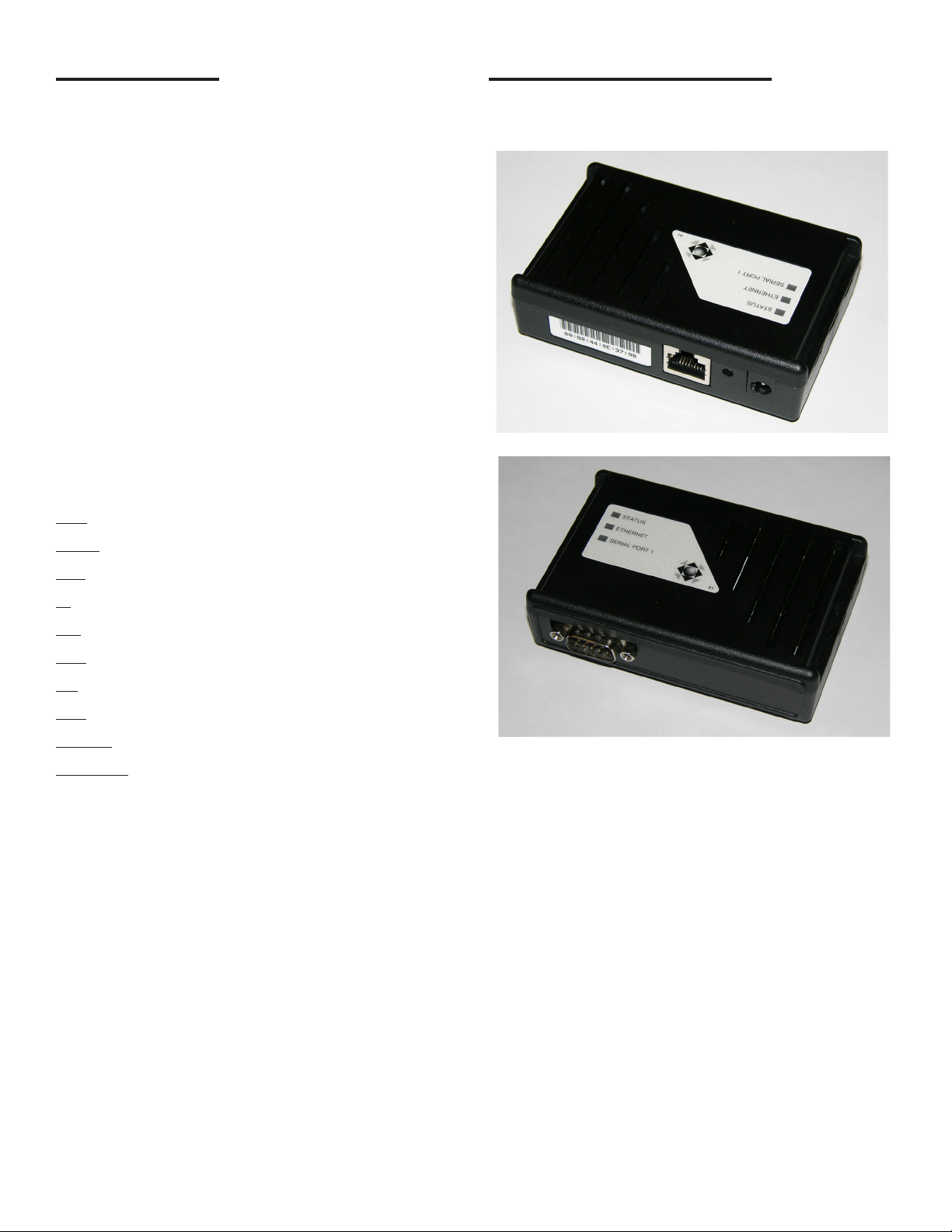
Figure 1: TS-EPS Ethernet Connection Side
Figure 2: TS-EPS Serial Cable Connection Side
2. Assemble the TS-EPS unit in the following order (see
Figure 2):
a). Connect the serial interface cable (provided)
from the male serial connection socket on the
TS-EPS to: Comm 1 on a FFS ATG, the RS-232
card on a TLS-350, or the appropriate port on
another manufacturer’s ATG. Some models may
need a DB-9 to DB-25 adaptor (also known as a
“gender changer”).
b). Plug one end of a RJ-45, 10 Base-T Ethernet
cable into the TS-EPS LAN Port and the other
end into the server or server hub.
c). Plug the power adapter into the back of the TS-
EPS and the 115 VAC plug into an electrical
outlet. There is no on / off power switch. As
soon as the TS-EPS is connected to the power
source, the device is active.
4
Page 5

During the reboot process, the LEDs (STATUS,
ETHERNET and SERIAL PORT 1) of the TSEPS will transition from red to steady green. If
the STATUS LED is not steady green after 1
minute, refer to the Troubleshooting section at
the end of this document.
d). Install the TS-EPS on a vertical or horizontal
surface using the accompanying mounting
bracket and four (4) appropriate fasteners (e.g.
dry wall screws).
Figure 3: TS-EPS Mountin Bracket
3. Once the connections are made, the unit will turn
on and become ready for use. The TS-EPS will run
onboard diagnostics and the LEDs will light.
Network Congurations
There are many possible network congurations that the
TS-EPS can integrate with. Below are two common setups:
frame relay networks and cable/DSL connections.
Frame Relay Networks
EPS
Hub
Figure 4 - Frame Relay Network
When setting up a TS- EPS on a frame relay network, the
router will have a public IP address (provided by the site).
The router needs to be programmed to route the trafc it
receives on port 8001 to a private IP address. The TS-EPS
is programmed with that private IP address and the route
on the TS-EPS is programmed as: Gateway = the IP of
the router and Destination = the IP of the rewall where
SSA is. The site in System Sentinel AnyWare (SSA) and/or
System Sentinel will be programmed with the public IP of
the router and port 8001.
Router
(Frame Relay)
Internet
SSA Server
When the NDS is powered up, the LEDs will ash to
indicate normal operation. The following LED colors and
patterns will be displayed during normal startup, if no
errors are detected.
• Status LED – initially this LED will be yellow, but will
quickly turn green. If the status LED is solid green, then
the NDS does not have a permanent IP address and
is trying to obtain one from a DHCP server. If the LED
is blinking green, it means the NDS has obtained an IP
address and is ready to use. Red indicates a fatal error.
• Ethernet LED – this LED will either be off, green or
blinking green/yellow. A green LED means that a good
Ethernet link has been established and the unit is on
the network. The LED will blink green/yellow to show
network activity.
• Serial port LED – this LED will normally be yellow or
green. Yellow indicates a port that is not in use. Green
indicates a port that is in use. The green LED will blink
when data is transmitted or received. It will blink 2 times
per second when data is continuously transmitted or
received. A red LED indicates that an error condition
was detected.
Cable/DSL Connections
or
DSL Router
EPS
- or -
Cable Router
Figure 5 - Cable/DSL Connections
When setting the TS-EPS up on a cable/DSL connection,
the ISP (Internet Service Provider) will provide a cable/
DSL modem and a public, static IP. The TS-EPS will then
be programmed with the provided public IP address and
connected to the Internet via the modem.
A router could also be added to this conguration for added
security and to allow other devices to share the same public
IP. If a router is installed, it will be programmed to have the
public IP address and to route any trafc received on that
public IP. The router will then send any data received on
that public IP address for 8001 to a private IP address.
The TS-EPS is programmed with the private IP address
and the route for the TS-EPS will be: Gateway = private
IP address and Destination = IP of the rewall where SSA
resides. The Site in System Sentinel AnyWare (SSA)
and / or System Sentinel will be programmed with the
public IP of the router and port 8001.
DSL or Cable
Modem
Internet
SSA Server
5
Page 6

Getting Started
Connect the internet and then the power wire from the
power adapter to the power connection socket.
There is no turn on / off button. As soon as you connect
TS-EPS to the power line, the device will be on. During
the reboot process, the lights of the LEDs (STATUS,
ETHERNET and SERIAL PORT 1) of the TS-EPS change
to show green when connected. If the TS-EPS does not
show the STATUS as green after 1 minute, contact FFS
Technical support (800-984-6266).
Setup Communication Parameters
By using the Port Server Utilities®, nd the TS-EPS
connected to internet:
By using the IP address assigned from your service
provider or using the one that TS-EPS obtained, launch a
browser and enter this IP address as a URL. You should
see a welcome screen that describes the unit.
Figure 7: TS-EPS System Welcome Screen
Click on Serial Settings on the side bar to bring up the
following screen.
Hover the mouse pointer in the window to
bring up the IPv6 and IPv4 message box.
Figure 6: Port Server Utility Screen: iPV4 and iPV6 Values
Ask your internet provider to reserve an IP address to your
TS-EPS. If no address is reserved for the TS-EPS, TSEPS will obtain one that is available from the DHCP server.
Figure 8: Serial Setting Screen
Here, you can set the communication parameters for your
serial communication to the tank gauge.
6
Page 7

Network Interface Settings
Network Interface settings is where the IP Address and
subnet mask (netmask) are entered.
This information can be supplied by the Network
Administrator or ISP (Internet Service Provider).
IP Routing
IP Routing is where the gateway address or network routes
are programmed. This is needed when connected through
re-walls or routers.
There may be several routes that need to be programmed
when connecting through a complex network.
7
Page 8

SSA Settings
From SSA, there is a page where you can program the TS-EPS for the site that has such device. The following gure
shows the interface once a particular site has been selected:
Figure 9: SSA Setup
The Default Host Address is the IP address of the TS-EPS and Port will be always 8001.
Default values can be set thru SSA Router as it shown below (Conguration and also be modied in the SSA web screen
under System/Congure).
Figure 10: Set up SSA Router
8
Page 9

TS-EPS Diagnostics
The TS-EPS has the capability to syslog events in the web interface provided by default from Systech®. To access such
sylog and other interactive parameters from the TS-EPS, enter the IP address of the TS-EPS in the URL of a browser and
you will have access to syslog and other conguration parameters of the TS-EPS:
Figure 11: TS-EPS Syslog Screen
Green colored text means information, yellow means warning and red means dangerous messages respectively.
9
Page 10

Page intentionally blank
10
Page 11

Page intentionally blank
11
Page 12

©2012 INCON 000-1071 Rev. E
3760 Marsh Road ● Madison, WI 53718 U.S.A.
Tel: +1 608 838 8786 ● Fax: +1 608 838 6433 ● www.franklinfueling.com
Tel: USA & Canada 1 800 225 9787 ● Tel: Mexico 001 800 738 7610
 Loading...