

Page 1

TS-DIM
Installation Guide
Manual # Revision Date Changes from Previous Revision
000-2044 B Aug. 2012 Added Cabling and Programming information
Franklin Fueling Systems • 3760 Marsh Rd. • Madison, WI 53718 USA
Tel: +1 608 838 8786 • 800 225 9787 • Fax: +1 608 838 6433 • www.franklinfueling.com
Page 2

Preface
This manual contains instructions for the installation of the INCON TS-DIM (Dispenser Interface Module), which monitors
transactions between dispensers and the consoles that control them.
Instructions for installing or servicing dispensers, consoles, and tank monitors are not included. For more detailed
information on other products, always refer to the documentation provided by the equipment manufacturer.
Abbreviations and Acronyms
DBox - Pump manufacturer’s Distribution Box
EGD - Electronic Gas Dispenser
MPD - Multiple Product Dispenser
MOC - Major Oil Company (term used by Gilbarco in G-SITE systems)
SPD - Single Product Dispenser
TS-DIM - Dispenser Interface Module
POS - Point of Sale terminal
PC - Personal Computer
Notice
INCON reserves the right to change this document and specications at any time without notice. INCON makes no
expressed or implied warranty with regard to the contents of this manual. INCON assumes no liability for errors or
omissions, or for any damages, direct or consequential, that result from the use of this document or the equipment that it
describes.
Trademarks
INCON® and Tank Sentinel® are registered trademarks of Intelligent Controls. All brand, and product, names are
trademarks or registered trademarks of their respective companies.
Copyrights
Copyright © 2004 by Intelligent Controls (INCON). Copyright © 2004 by Progressive International Electronics, Inc. (PIE).
No part of this publication may be reproduced in any form without the prior written consent of INCON. All rights reserved.
Patents
The INCON TS-DIM is manufactured by Progressive International Products (PIE) and is protected under one, or more, of
the following U.S. patents: 5,790,410, 5,831,861, 5,694,326, 5,663,887, 5,557,529, 5,394,336, 5,361,216, 5,270,943, and
5,108,742.
Contacting INCON
Please feel free to contact us by mail at:
Franklin Fueling Systems
3760 Marsh Rd.
Madison, WI 53718 USA
Or contact us by phone, fax, or email:
Tel: 608-838-8786 Email: FFSsales@fele.com
Fax: +1 608 838 6433 FFSTechsupport@fele.com
International Tel: Mexico 001 800 738 7610
Ofce Hours: 8am to 5pm CST - Monday through Friday
Please visit our web site at www.franklinfueling.com
2
Page 3

Contents
Preface.............................................................................................................................. 2
Abbreviations and Acronyms ..................................................................................................2
Notice ......................................................................................................................................2
Description of TS-DIM Components .......................................................................................5
System Evaluation - Important Site Survey ............................................................................ 5
System Installation Overview ......................................................................................... 5
System Installation Requirements .......................................................................................... 5
TS-DIM General Installation Steps – For Electronic Dispensers ............................................6
TS-DIM General Installation Steps – Wiring the TS-DIM ........................................................ 8
Pump Specic Installation
TS-DIM / G for Gilbarco Electronic Dispenser .........................................................................9
TS-DIM / GS for Gilbarco MOC G-SITE Systems .................................................................. 11
TS-DIM / W for Wayne / Dresser Electronic Dispenser .......................................................... 13
Smart Fuel Controller Connection ........................................................................................ 17
DIM Diagnostics ............................................................................................................. 19
Clearing the Database Using Privileged Mode ..................................................................... 21
Using the Internal Diagnostics to Collect Site Data .............................................................. 22
Acquiring and Saving Wayne Dispenser Line Factors .......................................................... 23
Programming the Tank Gauge .............................................................................................. 24
Troubleshooting ............................................................................................................ 25
General Technical Information ..................................................................................... 26
TS-DIM Installation on a T5 Series Console ...............................................................27
3
Page 4
Important Safety Messages
INCON equipment is designed to be installed in association with volatile hydrocarbon liquids such as gasoline and diesel
fuel. Installing or working on this equipment means working in an environment in which these highly ammable liquids may
be present. Working in such a hazardous environment presents a risk of severe injury or death if these instructions and
standard industry practices are not followed. Read and follow all instructions thoroughly before installing or working on this,
or any other related equipment.
As you read this guide, please be aware of the following symbols and their meanings.
Warning
Caution
Warning
Warning
Warning
This symbol identies a warning. A warning sign will appear in the text of this document when a potentially
hazardous situation may arise if the instructions that follow are not adhered to closely. A potentially hazardous
situation may involve the possibility of severe bodily harm or even death.
This is a caution symbol. A caution sign will appear in the text of this document when a potentially hazardous
environmental situation may arise if the instructions that follow are not adhered to closely. A potentially
hazardous environmental situation may involve the leakage of fuel from equipment that could severely harm
the environment.
Follow all applicable codes governing the installation and servicing of this product and the entire
system. Always lock out and tag electrical circuit breakers while installing or servicing this equipment
and related equipment. A potentially lethal electrical shock hazard and the possibility of an explosion
or re from a spark can result if the electrical circuit breakers are accidentally turned on during
installation or servicing. Please refer to the Installation and Owner’s Manual for this equipment and
the appropriate documentation for any other related equipment, for complete installation and safety
information.
Follow all federal, state, and local laws governing the installation of this product and its associated
systems. When no other regulations apply, follow NFPA codes 30, 30A, and 70 from the National Fire
Protection Association. Failure to follow these codes could result in severe injury, death, serious
property damage, and / or environmental contamination.
Always secure the work area from moving vehicles. The equipment in this manual is usually mounted
underground, so reduced visibility puts service personnel working on this equipment in danger from
moving vehicles entering the work area. To help eliminate these unsafe conditions, secure the area
by using a service truck to block access to the work environment, or by using any other reasonable
means available to ensure the safety of service personnel.
Warning
Warning
Warning
TS-DIM units must be installed in non-hazardous areas. The main box must be protected from
severe vibration, extreme temperatures and excessive humidity.
All equipment connected to the TS-DIM must be UL approved. Also, use standard RS232 and RS485
connections.
The TS-DIM is intended to be used with other devices such as tank monitors, which determine
whether leaks exist at a site. The TS-DIM device cannot determine if product leaks are present.
For Use in USA
Installation of the TS-DIM fuel control system must comply with the requirements of the National Electrical Code (NFPA
70), the Automotive and Marine Station Code (NFPA 30A), and all other federal, state, local and applicable safety codes.
For Use in Canada
Installation of the TS-DIM fuel control system must comply with the requirements of the Canadian Electrical Code, the
Flammable and Combustible Liquid Code, and all other federal, provincial, state, local and applicable safety codes.
4
Page 5
Description of TS-DIM Components
The TS-DIM collects information on all dispensed product and consolidates the data to a concise, easy-to-read format,
facilitating the inventory reconciliation process. The TS-DIM systems are made up of the components listed below. Using
this checklist, identify and familiarize yourself with each of the components in your shipment. For further clarication, refer
to the block diagrams at the end of each section in the dispenser specic installation portion of this manual.
Note: For both the mechanical and electronic installations, the technician will need a DB9M to DB9F straight cable and a
PC to complete the installation.
Component Checklist - TS-DIM
• TS-DIM Main Box, which includes: a communication cable to the tank monitor, power transformer and a connector for
the dispenser communications adapter cable.
• Pump Communication Cable Communications Adapter Cable, which connects the TS-DIM box to the fuel dispenser or
the POS.
• Installation Manual
• System Firmware
System Installation
System Evaluation - Important Site Survey
One important step before installing the TS-DIM is to take a site
survey listing all of the fuel dispensing equipment. A site survey
should include:
• Model numbers of all dispensers and DBoxes
• Names of equipment manufacturers
• Number of dispensers
• A simple drawing showing the station layout
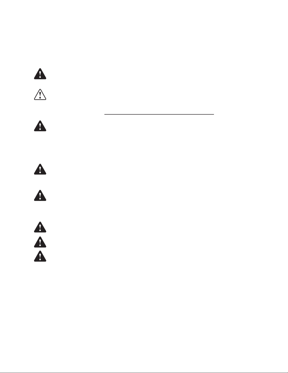
System Installation Overview
Install the TS-DIM system in the following order:
1. Install the controlling console and dispensers according
to the manufacturer’s specications. Test the dispensers
with the console for proper operation. See the System
Installation Requirements section that follows for further
information.
2. Install a tank monitoring system according to the
manufacturer’s specications. See the System Installation Requirements section that follows for further
information.
3. Mount the TS-DIM. Refer to the TS-DIM General Installation section of this manual for further information.
4. Connect the system components to the specic dispenser box (DBox). See the Pump Specic Installation section
for the appropriate brand of dispenser.
5. Test the TS-DIM with the internal Diagnostics, and map out the meters (refer to the Diagnostics section for further
information).
6. Connect to the tank monitoring system and fully test the integrated system.
Figure 1: TS-DIM Installation Overview
System Installation Requirements
In preparation for the TS-DIM installation, ensure that the following requirements have been met.
1. Following the manufacturer’s installation instructions, install the dispensing equipment (dispensers and DBoxes).
2. Test all of the dispensers in stand-alone (manual) mode.
3. Test all of the dispensers with the same brand of console to check basic dispenser functionality and to conrm a
working communications link between the DBox and the dispensers. On dispensers which have programmable
identication numbers, ensure that the numbers are set correctly. If multiple dispensers contain the same I.D.
number, communication conicts will occur. All dispensers and communications should function properly before
proceeding with TS-DIM installation, but, if they don’t, please contact that equipment’s vendor / manufacturer.
5
Page 6
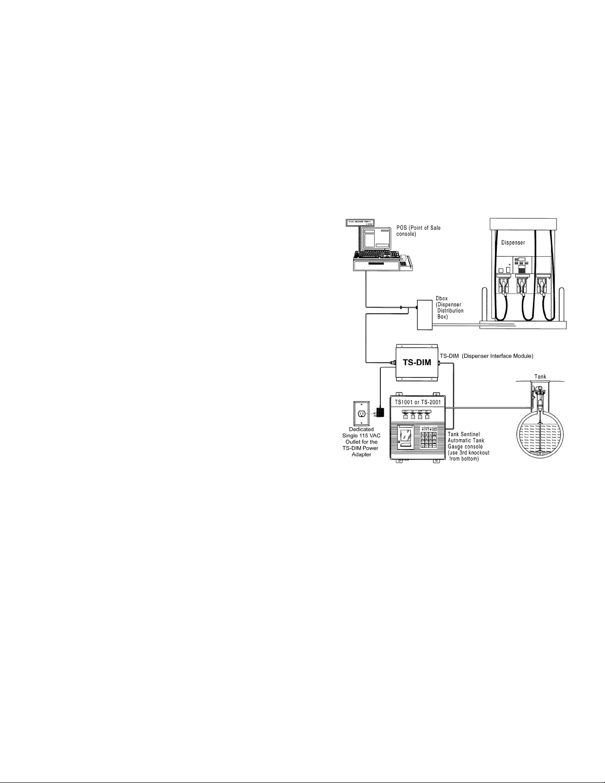
TS-DIM General Installation Steps – For Electronic Dispensers
1. A junction box with a single receptacle outlet must be provided (see the TS-DIM Power Requirements on page 7).
2. Securely mount the TS-DIM main box in a non-hazardous location according to the suggested layout in the Tank
Monitor Installation Instructions.
3. Referring to the connector / jumper layout diagrams that follow, verify all jumpers on the TS-DIM main board are
set according to the specic application requirements. These jumper settings have been set by the manufacturer
and should not need to be moved. Only the jumpers on SW2 may need to be adjusted depending on the
application. These jumpers allow the TS-DIM to be congured for daisy-chaining together using RS-485 multidrop circuitry (refer to the three diagrams in this section).
4. Plug the power adapter into the dedicated 120 VAC outlet to apply power to the TS-DIM system.
5. Connect the TS-DIM to the DBox.
6. Run internal DIM Diagnostics (Page 19), which will perform a preliminary test and gather data. Program the ATG
and refer to the TS-DIM General Installation Steps - Wiring the TS-DIM section for information on connecting a
RS232 serial port cable (eld supplied) from Host1 / RS-232 on the TS-DIM to a PC.
7. Connect the TS-DIM to the ATG.
Top View of TS-DIM Main Board
J3
AC pwr
Diagnostic Port
J8
J4
Host1/
Rs485
J5
RS485
Link to
J2
Auxilliary/RS232
J1
Host1/RS232
next box
W2
1
2 10
1 9
2
3
4
5
6
7
8
Pinouts for
J4 & J5
A 1
B 3
GND 2
W1
1
2 10
1 9
2
3
4
5
6
7
8
W2
1
2
3
4
5
6
7
8
BR 1
BR 2
DB (7/8)
P 1
P 2
A1
A2
A3
Note: 1 = Jumpered
0 = No Jumper
Parity
P1 P2
0 0 None
1 0 Odd
0 1 Even
1 1 N/A
W3
+
-
RTS
Tx Rx Tx Rx Tx Rx
Diag Host1 Aux
Jumper Detail
Aux
Device
Address
Device Address
A1 A2 A3
0 0 0 0/10
1 0 0 1/11
0 1 1 2/12
1 1 0 3/13
0 0 1 4/14
1 0 1 5/15
0 1 1 6/16
1 1 1 7/17
J6
1 Adapter Connector
W1
1
2
3
4
5
6
7
8
BR 1
BR 2
DB (7/8) Host 1
P 1
P 2
Reserved
Reserved
Reserved
Baud Rate
BR1 BR2
Data Bits
DB
0 7
1 8
0 0 1200
1 0 2400
0 1 4800
1 1 9600
Figure 2:TS-DIM Main Board Jumper Selections
6
Page 7
TS-DIM Power Requirements
The TS-DIM must be powered from a dedicated 115 VAC single circuit breaker, with no
other devices connected to the power receptacle or breaker. Do not use a switched-
neutral breaker. The neutral must come directly from the neutral bus in the electric
supply panel. No other neutral circuits may be connected to this wire.
The electric supply system earth bond must connect to a driven ground rod or other
earth bonding system that complies with Article 250 of the National Electrical Code.
Failure to comply with these requirements will void the warranty.
Top View of TS-DIM Adapter Board
Rx1
Tx1
Pump Type
Interface
Option
LEDs
Rx2
Tx2
J 3
J 2
H2
H 3
SW 1
A B C D
SW 2
A B C D
SW 3
A B C D
H 1
Settings
A B C D
0 = on
1 = off
off - on
Pump Type (SW 1)
A B C D
Non-Selected 0 0 0 0
Gilbarco 1 0 0 0
Wayne 0 1 0 0
Tokheim 1 1 0 0
Gilbarco G-site 0 0 1 0
1
XPIC
0
1
Layout for H2 & H3
1
2
3
Wayne
H2 & H3 jumpered 1-2
Gilbarco
H2 & H3 jumpered 2-3
Interface Type (SW 2)
A B C D
Non-Selected 0 0 0 0
Current Loop 1 0 0 0
RS422/RS485 0 1 0 0
TOK Standard 1 1 0 0
RS232 Full Duplex 0 0 1 0
0
RS232 Read Only 1 0 1 0
Options Type (J9)
Refer to Pump Specific Installation Instructions
Figure 3: TS-DIM Adapter Board Jumper Selections
7
Page 8

TS-DIM General Installation Steps – Wiring the TS-DIM
Wiring the TS-DIM to a Dbox and Power Receptacle
1. With all of the power off, install and wire the single outlet receptacle to a dedicated 10 circuit breaker in the power
panel. Label the circuit description on the power panel door “TS-DIM power only.”
2. Wire the TS-DIM to the Dbox. Information about wiring to the Dbox, or
Dbox & Controller, or G-Site Controller is found on pages 11 to 17 in this
2.0"
manual under the appropriate section heading. The TS-DIM will be wired to
the console in the following section.
3. Connect your DB9 serial cable from the Diagnostic port on the TS-DIM to
7.5"
(4) Mounting Holes for #8 Screws
the serial port on your PC.
Note: The Diagnostic port is used for diagnostics and sitemapping (see page 19).
For computers without serial ports, use a serial port to USB converter.
4. Apply power to the TS-DIM only (plug the TS-DIM power adapter into the
TS-DIM Dimensions
single outlet receptacle and turn on the TS-DIM circuit breaker).
Wiring the TS-DIM to a T1 Series Console
Turn off the main power source / all power sources that terminate in the console before working on or servicing this
equipment. Failure to do so will create a lethal electrical shock hazard.
1. Make sure all power to the tank gauge console is turned off at the power source.
2. On the right side of the console, use the third knockout from the bottom for the TS-DIM, 3 conductor cable wiring
(P / N 600-0207).
3. Install a clamp tting at the console and insert the wires through the opening. Remove the plastic safety shield
and terminate the wires as follows:
a. Wire 485A to Terminal 485A
b. Wire 485B to Terminal 485B
c. Wire S.RTN to Terminal S.RTN
Note:
There may be TS-LLDI interface wires already connected to the RS-485 terminals. In this case, remove one wire
and twist it together with the appropriate TS-DIM wire. Reinsert these into the correct terminal and tighten the screw.
8.5"
TS-DIM
4. Reinstall the plastic safety shield and tighten the clamp.
To Dispenser Dbox
Dedicated
Single
115VAC
Power
Outlet
Figure 4: TS-DIM to Dbox and Receptacle Power Wiring
To Tank Sentinel Console
DB9 to DB9
To - PC
COMM
X Serial
Port
PC
Host 1 / RS485 Port
TS-DIM
Dispenser
Interface
Module
Diagnostic Port
FFS Console
Or...
Other Dbox
Adapter Cable N / A
for TS-DIM / M
Dedicated Single
115VAC Power Outlet
TS-DIM
Dispenser
Interface
Module
Figure 5: TS-DIM to Console Wiring
INCON P / N 600-0207
Host 1 / RS485
Port
8
Page 9
Pump Specic Installation
TS-DIM / G for Gilbarco Electronic Dispenser
Gilbarco MOC (Major Oil Company) G-SITE Systems are specially congured. For Gilbarco MOC instructions and
installation requirements, refer to the Gilbarco G-SITE installation section that follows this one.
Follow instructions in the TS-DIM General Installation section and perform general installation procedures and preliminary
testing procedures using the internal DIM Diagnostics (page 19). Then, follow the specic instructions for connecting the
TS-DIM system to the appropriate Gilbarco distribution box (DBox). See the Gilbarco DBoxes Table that follows for further
information.
Proceed with the TS-DIM’s installation and refer to the TS-DIM Adapter Board Jumper Selections Diagram in the
preceding section (TS-DIM for Electronic Dispensers General Installation) for further information.
1. Verify that the adapter board’s SW1 jumpers will be set for the specic Gilbarco models.
2. If the Gilbarco system uses a current loop style Universal DBox or a TS1000 DBox, set the adapter board’s SW2
jumpers for current loop. Plug the adapter harness into position J2. Disconnect the Gilbarco console / controller from
the distribution box and connect the Gilbarco style TS-DIM adapter cable (P / N 600-0201) to the Gilbarco DBox. Plug
the long end of the adapter cable into the TS-DIM DB9M connector on the end of the TS-DIM. See the TS-DIM to
Gilbarco DBox Universal / TS1000 Diagram later in this section.
If the Gilbarco system uses an RS422 style Universal DBox, set the adapter board’s SW2 jumpers for
RS422 / RS485. Plug the adapter harness into position J3. Disconnect the Gilbarco console / controller from the DBox
and connect the Gilbarco style TS-DIM adapter cable (P / N 600-0202) to the Gilbarco DBox. Plug the long end of
the adapter cable into the TS-DIM DB9P connector on the end of the TS-DIM. Refer to the TS-DIM to Gilbarco DBox
Universal / TS1000 Diagram later in this section.
If the Gilbarco system uses a PA01330000 DBox, set the adapter board’s SW2 jumpers for current loop. Plug the
adapter harness into position J2. Cut off the ‘T’ end of the TS-DIM adapter cable (P / N 600-0201). Locate an unused
position in the Gilbarco DBox, check that the switch is in the ‘Isolate’ position, then connect the cut end of the adapter
cable to the Gilbarco DBox at this position. At this point, move the switch to the ’Normal’ position. In the event that the
DBox positions are all in use, wire the TS-DIM adapter cable in series with an existing pump. Reference Diagram: TSDIM to Gilbarco DBox PA01330000.
If the Gilbarco system uses a PA03060020 DBox, set the adapter board’s SW2 jumpers for current loop. Using
connectors P / N 601-1003 and P / N 601-1004, plug them into the Monitor Cable Input then plug the adapter harness
into position J2. Disconnect the Gilbarco console / controller from the distribution box and connect the Gilbarco style
TS-DIM adapter cable (P / N 600-0201) to the Gilbarco DBox between the DB9 and RJ45 adapters. Plug the long end
of the adapter cable into the TS-DIM DB9P connector (position J2 on the adapter board). See the TS-DIM to Gilbarco
DBox PA03060000 Diagram following this section.
3. Return to the TS-DIM General Installation section for remaining system installation procedures.
Gilbarco DBoxes
Gilbarco dispensing systems use several types of distribution boxes. This table of DBox part numbers
with descriptions will assist you in determining which connection method to the TS-DIM meets your
requirements. Gilbarco uses two different electrical means of transmitting data — current loop and RS422.
It is very important to determine this prior to installing the TS-DIM.
DBox Part # Description
PA01330000 Old style DBox with circular DINN connector (current loop)
PA0261x000010 Universal DBox1 with DB9P male (current loop) — one board
PA0261x000020 Universal DBox1 with DB9P male (current loop) — two boards
PA0261x000011 Universal DBox1 with DB9S female (RS422) — one board
PA0261x000021 Universal DBox1 with DB9S female (RS422) — two boards
PA03060020 G-SITE DBox with RJ45 connector (current loop)
PA0242 TS1000 DBox2 with DB9P connector (current loop)
1 The Gilbarco Universal DBox may be congured as a one or two board unit, depending on the fuel site
dispensing equipment layout. If two boards and two inputs are used, multiple TS-DIMs are required for
pump control. Refer to Gilbarco document number MDE-2713 for detailed information on this product.
2 Refer to Gilbarco document number MDE-2381A or MDE-2382A for detailed information on this product.
9
Page 10

Gilbarco
DBox
Universal/
TS1000
Data Wire
to Pumps
TS-DIM/G Adapter Cable
(P/N 600-0202 for current loop)
(P/N 600-0201 for RS422)
TS-DIM/G
TS-DIM/G to Gilbarco DBox Universal/TS10000
Figure 6
Gilbarco Console
to Controller
Data Wire
to Pumps
Gilbarco
DBox
PA01330000
Gilbarco Console
TS-DIM/G Adapter Cable
(P/N 600-0201)
TS-DIM/G
TS-DIM/G to Gilbarco DBox PA01330000
Figure 7
to Controller
10
Page 11

Gilbarco
Dbox
PA03060020
Connector
(P/N 601-1003)
DB9 to RJ45
Adapters
TS-DIM/G
Connector
(P/N 601-1004)
TS-DIM/G Adapter Cable
(P/N 600-0201)
TS-DIM/G to Gilbarco DBox PA03060020
Figure 8
TS-DIM/G Console
to Controller
Pump-Specic Installation — TS-DIM / GS for Gilbarco MOC G-SITE Systems
If the Gilbarco system uses a MOC G-SITE point of sale system, special procedures must be followed to successfully
install a TS-DIM. Both the type of controller (C2, 486, Pentium, etc.) the G-SITE is using and the revision number of the
software running on the G-SITE are very important to know for installation and should be entered on a thorough site
survey.
Conrm that the G-SITE will support the EMC tank monitoring option which is a component of the BIR (Business Inventory
Reconciliation) interface. The software revision number, along with MOC type, indicate the ability of the G-SITE to support
this function. If the G-SITE does not have the correct revision software loaded, a software update is required from an
authorized Gilbarco distributor. If the G-SITE is EMC ready, proceed with TS-DIM installation. Otherwise, contact your
dealer for further assistance.
Follow the instructions in the TS-DIM General Installation section and perform general installation procedures and
preliminary tests using the internal DIM Diagnostics (page 19).
Proceed with installing the TS-DIM and refer to the TS-DIM Adapter Board Jumper Selections Diagram (Figure 2).
1. Verify that the adapter board’s SW1 jumpers are set for Gilbarco G-SITE models.
2. Set a jumper on position SW2 of the adapter board for RS232 full duplex. Plug the adapter harness onto
position J3.
3. Referencing the G-SITE installation manual, locate the G-SITE controller EMC tank monitor port. Connect the TSDIM to the G-SITE using the P / N 600-0205 cable and the RJ45 adapters P / N 601-1002).
Note: If G-Site is using C2 Style controller contact Tech Support for the correct parts and instructions.
Refer to Diagrams: TS-DIM to Gilbarco 486 G-SITE at the end of this section for more information.
Note: Some installations may require a longer cable than P / N 600-0205 or P / N 600-0207. If this is the case, FFS
recommends that the technician use a standard CAT5 cable (of any length) to replace the cable going from the TSDIM to the G-Site.
4. Return to the TS-DIM Installation Section for remaining system installation procedures.
The TS-DIM G-SITE reports all totals by meter number for each fueling position. Blender dispensers will report meter 1 to
hose 1 and meter 2 to hose 2 position on the TS-DIM. A blended product will report an increase for both meters.
11
Page 12

Gilbarco
G-SITE
Controller
C2 Style
TS-DIM/GS
RJ45 to DB9 Adapter
(P/N 601-1002)
RJ45 to DB25 Adapter
(P/N 601-1001)
Note: If the 600-0205 cable is not long enough for your installation, a standard CAT5
cable may be substituted.
TS-DIM/GS to Gilbarco C2 G-SITE
TS-DIM/GS G-SITE Adapter Cable
(P/N 600-0205)
Note: G-SITE systems must support EMC with BIR interface. Minimum software
levels must exist on the G-SITE for proper operation.
Gilbarco
G-SITE
Controller
486 Style
or Passport
TS-DIM/GS G-SITE Adapter Cable
(P/N 600-0205)
RJ45 to DB9 Adapter
(P/N 600-1005)
TS-DIM/GS
Note: G-SITE systems must support EMC with BIR interface. Minimum software
levels must exist on the G-SITE for proper operation.
TS-DIM/GS to Gilbarco 486 G-SITE or Passport
Figure 9
Dispenser Security Hub
601-1005
Part # 600-0205
Figure 10
Gilbarco Passport
1. Using TSP-GSDCBL connect the 600-1002 adaptor to the port on the TS-DIM/GS.
2. Connect the 600-1005 to the end of the dongle cable Gilbarco Part # M09747B010
3. Connect the dongle cable to Port on Dispenser Security Hub (port 5) if available
4. Setup EMS DIM 1 to G site and RS232/Duplex
5. Be sure Port on Security hub is set to EMC and Baud 1200, 7, E, 1
6. Query Dispensers.
PassPort 8.02TS-DIM/GS
Port 5
Dongle Cable
Gilbarco Part # M09747B010
12
Page 13

Pump Specic Installation — TS-DIM / W for Wayne / Dresser Electronic Dispenser
Following the instructions in the TS-DIM General Installation section, perform general installation procedures and
preliminary tests using the internal DIM diagnostics (page 19).
Proceed with installation and reference the TS-DIM Adapter Board Jumper Selections Diagram (Figure 2) in the preceding
section — TS-DIM for Electronic Dispensers, General Installation.
1. Verify that the adapter board’s SW1 jumpers are set for Wayne models.
2. On the adapter board, set the SW2 jumper for current loop.
3. Set jumpers on positions H2 and H3 for Wayne models.
4. Plug the adapter harness into position J2 on the adapter board.
5. Plug the adapter cable (P / N 600-0203) into the RLM II monitor cable input on the TS-DIM / W.
6. Locate the Wayne / Dresser distribution box and wire the other end of the adapter cable into an unused pump
position in the DBox. In the event that the DBox is full, wire the adapter in “series” with an existing pump. The
following chart shows the relationship between wire color and function.
Wire Color Function
Black Loop 1 –
Red Loop 1 +
Green Loop 2 –
White Loop 2 +
On Wayne / Dresser DBoxes with pumps wired into one side of the DBox board, only one loop needs to be connected;
for example, the Wayne / Dresser DBox TS-DIM / W Connection Example Diagram. For units with both sides of the
DBox board wired, Loop 1 and Loop 2 must both be connected. Refer to the TS-DIM / W to Wayne / Dresser — Typical
Installation Diagram for information on in which two loops are needed during installation.
13
Page 14

TS-DIM/W
Wayne/Dresser
DBox
TS-DIM Wayne/Dresser Adapter Cable
(P/N 600-0203)
Note: See the Wayne/Dresser DBox TS-DIM/W Connection Example Diagram below
for cable connections.
TS-DIM/W to Wayne/Dresser - Typical Installation
Figure 11
Data Lines to Dispensers
Data Lines to Dispensers
TS-DIM/W Adapter Cable
Wires Loop 1
Data Lines to Dispensers
TS-DIM/W Adapter Cable
Wires Loop 2
14
Communication Lines
to Console/POS
Wayne/Dresser DBox TS-DIM/W Connection Example
Figure 12
Page 15

Wayne Fusion DIM Connection
1. Setup the Fusion as described in the “Fusion Installation – HyperPIB-PAM-Console” manual. See step A Below.
2. Reboot the Fusion after changing the Fusion conguration.
3. Verify the Fusion setting
4. Setup the Dispenser Interface section of the console as it would be normally setup for Wayne dispensers.
5. Connect the Wayne DIM cable (600-0203)
• If the site has 6 or less dispensers wire the cable to GRIB Port 4
• If the site has more than 6 dispensers wire the cable to GRIB Port 9 (on second GRIB board)
6. Using Loop 1 of the Wayne DIM cable wire in one of the following ways
• If GRIB Port has a resistor installed in Pins 3&4 wire the Red (+) wire to Pin 3 and the Black (-) wire to Pin 4.
See Figure 56 on page 59 of the “Fusion Installation – HyperPIB-PAM-Console” manual.
• If the GRIB Port does NOT have a resistor installed in Pins 3&4 wire the Red (+) wire to Pin 1 and the Black (-)
wire to Pin 4. (Refer to the “Fusion Installation – HyperPIB-PAM-Console” manual).
7. Once the connection has been made verify communication across the GRIB by looking at the LEDs for the GRIB
port that the DIM is connected to.
• If the LEDs are on SOLID the loop is broken meaning either the Fusion is setup incorrectly or the DIM is not
wired properly to the Fusion
• If the LEDs are ickering quickly the Fusion is communicating properly with the DIM
8. Once communication has been established you need break all current loops and save the Line Factors.
a. Disconnect each and every GRIB Port connector that has a dispenser wired to it, but leave the DIM
connected. Leave each of the ports disconnected for one minute.
b. Reconnect all of the GRIB Port connectors and wait another minute
c. On the T5 series console under Tools save the line factors
9. Query the dispenser normally.
A. Congure Wayne Fusion:
1. Login in to Fusion -Select Conguration>Generic
2. From Drop Down Select BIR Port click Search.
3. If the site has 6 or less dispensers wire the cable to GRIB Port 4
4. If the site has more than 6 dispensers wire the cable to GRIB Port 9 (on second GRIB board)
Be sure to click enabled link and change to 1-enabled.
Second Port should be left blank and second port pump set to 0.
Once complete, “Submit to Fusion” link must be clicked to save GRIB port setup.
B. CABLE Connections.
Use Pins 1 and 4 for Current loop cable:
PIN 1 + Red Wire
PIN 4 – Black wire.
Wayne Line Factors
When interfacing with Wayne / Dresser DBoxes or Wayne Fusion systems, the dispenser calibration data known as line
factors must be saved in the TS-DIM. This procedure should be followed after in initial startup on the TS-DIM module.
Wayne version 3.5 and below will not have the saving of line factors. Anything above Wayne version 3.5 will. The
customer can check the software version by hitting v at the Diag> prompt, then hit T at Enter Selection. The details of this
procedure can be found under the DIM Diagnostics section of this manual. Page 23.
Checking Wayne version:
15
Page 16

Pump Specic Installation — TS-DIM / T for Tokheim Electronic Dispenser
Follow the instructions in the TS-DIM General Installation section, and then do preliminary tests using the internal DIM
Diagnostics (page 19).
Install your TS-DIM and refer to the TS-DIM Adapter Board Jumper Selections Diagrams in the TS-DIM for Electronic
Dispensers, General Installation section.
1. Verify that the adapter board’s SW1 jumpers are set for Tokheim models.
2. Determine the type of electrical communications used by the Tokheim system. Match the TS-DIM with the
Tokheim system by making the corresponding jumper selections on position SW2 of the adapter board. For
Tokheim M98 and M94 Power Centers or 67 DBoxes, make the Tokheim Standard selections. For the 67B DBox,
make the RS422 / RS485 selection on position SW2.
Note: That communication for the 67 and 67B DBoxes can be modied in the eld, so that model number may not
accurately reect the communication method. Contact the Tokheim service company responsible for site service to
conrm DBox settings.
3. Plug the adapter cable (P / N 600-0204) into TS-DIM monitor cable input, and plug the adapter harness into J2 on
the adapter board.
4. Locate the round black connectors on the existing console to DBox cable. Disconnect the existing
console / controller cable from the Tokheim M98 / M94 Power Center, the 67 DBox, or the 67B DBox. Attach the
TS-DIM adapter cable to the cable ends from the console / controller and from the DBox / power center (see the
TS-DIM / T for Tokheim — Typical Installation Diagram for further information).
Tokheim 67B Note: If the cable to the controller is connected to the top board in the 67B then the comm is RS422.
If the cable is connected to the lower board in the 67B then the comm is RS232.
Program as “tokheim std” in the EMS dim programming.
Tokheim
67/67B DBox
or M94/M98
Power Center
Console to Controller
TS-DIM/T Tokheim Adapter Cable
(P/N 600-0204)
TS-DIM/T
TS-DIM/T to Tokheim - Typical Installation
Figure 13
Tokheim
16
Page 17

Smart Fuel Controller Connection
Follow directions below to connect the INCON console to VeriFone’s Smart Fuel Controller (SFC). Using this interface
allows obtaining sales information for Inventory Reconciliation or Vapor Recovery Monitoring.
At this time, VeriFone only supports Gilbarco dispensers. Therefore a Gilbarco Dispenser Interface Module (DIM) cable
part number TSP-GDCBL will be required.
Note: Sites with 9 or more dispensers will require a second DIM and a second cable.
1. To begin, you will need to modify the 600-0201 cable from the TSP-GDCBL. Cut the “Y” end off and discard.
This will remove two of the DB9 connectors leaving you with an 8’ section of cable containing a Red and a
Black wire.
2. Power down the SFC and locate the current loop wire from the AUX board to the distribution board.
SFC Aux Board
Current Loop Wire
(Orange Wire)
SFC Distribution
Board
Dispensers 1-8 Dispensers 9-16
Figure 14: Smart Fuel Controller Connection
Do NOT cut
White Wire
3. Locate the middle point in the Current Loop wire and cut the negative polarity (orange) wire.
4. Connect the positive (red) wire on the 600-0201 to the negative side of the orange wire closest to the SFC
distribution board.
5. Connect the negative (black) wire on the 600-0201 to the positive side of the orange wire closest to the SFC
AUX board.
Note: Do NOT cut the white wire going from the AUX board to the distribution board.
6. Power down the TS-DIM and connect the 600-0201 cable to the RLM2 Monitor Cable Input port.
17
Page 18

16
SFC Aux Board
Do NOT cut white wire
Orange wire
SFC Distribution
Board
Dispensers 1-8 Dispensers 9-16Dispensers 9-
Modified TSP-GDCBL Cable
7. Power up the T5/DIM.
Figure 15: Modied TSP-GDCBL Cable Installation
18
Page 19

DIM Diagnostics
Extensive testing and data collection is available to the user through the TS-DIM’s built-in diagnostic port, which is
physically located on the front panel of the TS-DIM (see the TS-DIM Front Panel Diagram below). Accessing the
diagnostic port requires a computer running a terminal emulation program such as Hyperterm, PuTTY or Procomm. A
physical connection is made using a serial cable (straight through). Once the connection is established, power up the
TS-DIM and a prompt will appear. To view a help menu, type ? at the prompt.
RLM II Monitor
Cable Input
AC Input
TS-DIM Front Panel View
Figure 16: TS-DIM End Panel Diagram
TS-DIM Rear Panel View
The terminal emulation program (i.e Hyperterm, PuTTY or Procomm) must be set to the following parameters to work
properly.
Baud rate 57,600
Data bits 8
Parity none
Stop bits 1
Flow control none
Terminal emulation setting ANSI
TS-DIM Power Up
When the TS-DIM powers up, the screen below will appear.
TS-DIM Help Menu (?)
The screen below shows the help menu. To display a menu of available options, simply type ? at any of the prompts. The
only section that will be needed for installation is the Diagnostic section: for information or help with any other section,
please contact Technical support.
19
Page 20

Accessing the Internal Diagnostics
The database section of the diagnostics will show the transaction totals for each fueling position.
1. At the DIAG-> prompt, enter D for the diagnostic section.
2. Next, at the Select Section: prompt, enter A for the database section.
3. At the DBASE-> prompt, enter D for the display pump block option.
4. Finally, at the Select: prompt, enter 0 for the total volume option.
5. The screen should look like that below.
Denitions
Fueling Point - anywhere a vehicle can stop and dispense fuel. Most dispensers have two fueling points (front and back).
Meter # (Product) - each type of product that can be dispensed from a fueling point (position) will be assigned a meter
number Hn (n = 1 through 8).
Grade # - the diagnostic program will show eight possible grades for each Fueling Point and assigns a Grade # to a Meter
(product) when you dispense each product at each fueling point (position).
Tank # - this is the Tank # in the FFS Tank Sentinel that the product will come from when dispensed from this Meter
(product). If this meter is a blended product, then supply both tank numbers and the blend-percentage from the
primary tank.
Blend % - is the percentage of the blend coming from the primary tank (the tank which supplies the greatest amount of
fuel to the blend) Primary non-blends = 100%.
20
Page 21

Clearing the Database Using Privileged Mode
Normally, at startup, the totals for all pumps are zero, but, in some situations, the Fueling Positions may contain data that
needs to be cleared in order to start the meter mapping process. The Privileged diagnostic mode will have to be entered
in order to access the Clear Database function.
Entering Privileged Mode
At the DIAG-> prompt, select S. An Access Code will be displayed and a Security Code will be requested. To calculate
the security code subtract the access code from 100 and then reverse the digits. See the following example.
Example: If the Access Code = 25 and 100-25 = 75, then reverse the 75 to 57. The Security Code = 57.
Note: For an access code that results in a single digit (i.e. 98: 100-98 = 2), assume a 0 before the digit
to get the security code (i.e. 2 → 02 → 20).
Clearing the Database
These steps will clear the totals from the database and reset all of the Fueling Positions to zero. This process can be
repeated at any time during the meter mapping process to get back to a clean database.
1. Follow the above instructions to enter the privileged mode.
2. At the DIAG(P)> prompt, select D for diagnostic section.
3. Next, at the Select Section: prompt, enter A to select the database.
4. At the DBASE-> prompt, enter C to clear the database.
5. The TS-DIM will ask the following two questions:
a. “Are you sure you want to clear the database?” Answer Yes to clear the database.
b. “Database Cleared --- do you want to store in NVRam?” Answer No.
1
1
no
1 Reg 7 7 4 Reg
2 Mid 5
3 Sup 3
100
60
100
1
2
2
no
2
5 5 Mid
3 6 Sup
5 (not shown)
13 Diesel 1
100
3
3
7 Reg 7
8 Mid 5
9 Sup 3
4
no
100
60
2
100
no
3
2
no
4
7 10 Reg
5 11 Mid
3 12 Sup
Figure 17: Fueling Point Table Example
21
Page 22

Using the Internal Diagnostics to Collect Site Data
Be prepared, some of these steps involve dispensing at least 1/10 of a gallon of each product from all Fueling Points. See
the following section for more details.
A. The FFS Tank Sentinel console must be programmed with the information from the TS-DIM for site conguration and
layout.
B. Make copies of the blank fueling point tables (Figure 21) so that all of the information can be recorded for each fueling
point and meter.
C. See Figure 20 for an example of how to ll out a fueling point table.
D. Enter the Fueling Point No.(s) at the top of each table.
E. Start at Fuel Point #1, each product that can be dispensed at this fueling point is represented by a Meter #. For
example, if a fueling point can dispense Unleaded, Midgrade, and Super, then it will have three meters. Enter a meter
number for each product that can be dispensed at this fueling point. Note that although the table shows eight possible
meter positions per fueling point, usually only three or four will be used (Figure 21).
F. At Fueling Point 2, each product should again be assigned to a meter. The meter number will continue to increase and
should never be duplicated.
G. In the case of blenders, each meter (product) will be dispensed from a primary tank (A) and, maybe, from a secondary
tank (B). Record the tank number(s) for each meter as programmed in the FFS tank gauge. If the meter is a blended
product, then the greatest percentage of the blended product will come from the primary tank and should also be
recorded.
H. When there are two opposing Fueling Points (one dispenser), each will have a meter with the same tank conguration.
These meters should be listed opposite each other in the Fueling Point Table.
I. The internal diagnostics shows eight possible Grades for each Fueling Point. When the product is dispensed from
Meter 1, the total volume that was dispensed will show up in one of the Grade positions under Fueling Point 1. This
Grade number should be assigned to Meter 1.
J. Dispense product from each Meter and/or monitor sales activity to determine the Grade assignments of each Meter.
Note: Grade assignments may be consistent from Fueling Point to Fueling Point, but it is not guaranteed.
Note: Pay particular attention to changes in dispenser type, for instance: one island having a 3 + 1 gasoline and diesel
dispenser. The grade assignments can change drastically in this case. Mistakes in grade assignments can create
problems that will be very difcult to trace.
J. When the data collection is complete, disconnect the straight DB9 serial cable and nish connecting the TS-DIM to the
tank gauge.
Each block represents a fueling
point.
Each Number (1 - 8) represents
the Grade Number.
When the dispense is complete,
the volume will drop in one of the
grade numbers. This conrms the
grade number of the product that
was dispensed.
Figure 18: Pump Block Display
22
Page 23

Acquiring and Saving Wayne Dispenser Line Factors
The following instructions are only applicable for the TS-DIM installations in which the Wayne/Dresser DBox or Wayne
Fusion Controller are being used.
TS-DIM Saving of Line Factors
1. At the Diag prompt, hit D. You will see
2. For Select Section, choose the selection for Pump Section. (Will either be 2 or 3). Hit ENTER.
3. At the Pump> hit N
4. Break the current loop from the Wayne DBox / Fusion to the TS-DIM.. Wait 15 seconds. Reconnect the current
loop. On the Wayne Fusion, each Grib port will need to be disconnected individually at the Fusion. Unplug one at
a time, waiting 30 seconds before reconnecting. When reconnected, the port lights will ash quickly, then begin
to slow down. When they have decreased in speed, the connection is complete. If they continue to ash quickly,
disconnect and try again, increasing the wait time with each attempt.
5. Hit B. You will see
The above example shows Pump # 1 information. Allow pumping to continue and verify that all pumps received a Cal
Factor. The Cal Factor should populate with either a 1523, 2000, or IDDE. To see information from other pumps, you can
scroll back and forth by hitting Shift + to move to next Pump #, hit minus (-) to go to previous Pump #.
6. After Cal Factors have populated, Hit ESCAPE.
7. To Save the Cal Factors, hit F
8. To view the Cal Factors to conrm, hit A. Verify that each pump has a value under Stored Factors.
9. Disconnect from Hyperterminal or other emulator program. The storing of line factors is complete.
23
Page 24

Programming the Tank Gauge
NO. METERS: The total number of all Fueling Point Meters at the site. This is located under the SYSTEM menu. A value
above 0 will show the following menus:
RECONCILE: Enables reconciliation by programming schedule and time for gathering data. Located under the SETUP menu.
DIM Dispenser Interface: Program Meters, Fuel Points, and DIM address. This is located under the SETUP menu
REPORTS...RECONCILE: Program a schedule on a Shift basis, Daily schedule, Monthly basis, Shift History, or Daily
History — the RECONCILE menu is DIM-related and replaces the earlier Non-DIM Inventory Reconciliation menu
(reconcile is the last of the report choices)
TS-DIM Related Features
Sales and Delivery adjustment (in volume units) are available on a per-tank basis. These offsets allow adjustment to a
known discrepancy in reconciliation (e.g. when calibrating a meter, or when a product delivery doesn’t match the reported
delivery at the tank gauge).
Press MENU – DOWN – and M1 for SALES ADJ or M2 for DELIV ADJ.
SETUP
Setup Menu
SYSTEM
NO. METERS = 0
RECONCILE
SCHEDULE
TIME = 23:00:00
DIMM
DISPENSER INTERFACE
METERS (100 meters supported)
NONE
DAILY
SHIFT
Shift 1 = 7:00:00
Shift 2 = 15:00:00
Shift 3 = 23:00:00
METER N (shown typical)
Input the correct Tank Number for Tank A & Tank B
HH:MM:SS 24 Hour Format Input time
HH:MM:SS 24 Hour Format Input time
HH:MM:SS 24 Hour Format Input time
(For 2 shifts, use same time for shift 2 & 3)
FUEL PT = N Fuel Point # from WinTester data
GRADE NO. = N
TANK A = N
TANK B = 0Tank No. (Smallest % of a blend)
BLEND = 100 Blending Ratio % from Tank A
Input the total number of meters
at the site. (TS-DIM(s) sites)
HH:MM:SS 24 Hour Format
Input time (N/A for Shift)
Some prior-input values will be
present...correct as needed
Grade from WinTester data
Tank No. (Largest % of a blend)
24
FUEL PTS Fueling Points
FUEL PTS N Fueling Point N (shown typical)
DIM UNIT DIM Unit Number
- FUEL PT = 1
DIM FL PT DIM Fueling Point
- FUEL PT = N
Correct TS-DIM number
Correct Fuel Point # as req’d
Figure 19: Tank Gauge DIM Menu
Page 25

Troubleshooting
Troubleshooting Electronic Versions
Table 1 TS-DIM – Diagnostics – Electronic Dispensers
Problem Recommendation / Analysis
TS-DIM does not talk to the tank monitor.
TS-DIM does not talk to the terminal emulation
program.
See the “Testing the TS-DIM” section.
TS-DIM does not capture any data. • Make sure LED on adapter board is ashing.
• Run the a terminal emulation program utility.
• Check jumper settings on the TS-DIM - see Figure 5 (TS-DIM Connector /
Jumper Layout)
◦ Baud correct? (2400 = J2 jumpered)
◦ Parity correct?
◦ Stop bits correct?
◦ Data bits correct?
◦ Device address correct?
• Check power indicator on TS-DIM main board
• Check PC
◦ Comm port on PC OK?
◦ RS232 cable plugged into PC?
• Port parameters set correctly on the terminal emulation program?
• Refer to pump specic diagnostics section to make sure connections are
correct.
• Check software version in TS-DIM to make sure it is the latest revision.
• Check to ensure there are no console to dispenser connection errors.
• Contact INCON for assistance.
Seemingly random problems such as lock-ups or
memory corruption.
• Make sure all dispensers are idle at the beginning and at the end of a totals
Delivery or Sales reports corrupted. • Possibly caused by the DIM stuck in pump totalizer mode. (To check, pull the
• Reboot DIM. Always exit tank totalizer mode before disconnecting serial port
connection.
test.
• Make sure there are no console (POS) to dispenser connection errors.
• Make sure that the TS-DIM software version is current.
• Contact INCON for assistance.
cover to see if the DIAG LED is lit). Cycle power to the DIM.
Pump Specic Troubleshooting
Table 2 Gilbarco
Problem Recommendation / Analysis
LED (D5) is off and never ashes. • Console / POS not communicating with pumps.
LED (D5) is on solid. • Adapter cable is connected incorrectly.
• Wrong type of adapter communications input used - RS422 or current loop (refer to the TSDIM Adapter Board Jumper Selections diagram - Figure 2).
• Defective Cable.
All communications down on console / POS to pumps.
• Adapter cable not connected.
• Adapter cable connected incorrectly.
• Wrong type adapter communications input used - RS422 / current loop (refer to the TS-DIM for
Gilbarco Electronic Dispenser section of this manual).
• Defective cable.
25
Page 26

Table 3 Gilbarco MOC G-SITE
Problem Recommendation / Analysis
No data capture. • Is the EMC port on G-SITE enabled?
• Is the correct software version being used on G-SITE?
• Is the adapter cable into the correct port on G-SITE?
• Is the correct type of adapter being used?
Refer to the TS-DIM Adapter Board Jumper Selections Diagram.
TS-DIM is not answering G-SITE. • Are the settings correct on the adapter board? Refer to Figure 2 to check them.
All communications down on console / POS to pumps.
• Adapter cable not connected.
• Adapter cable connected incorrectly.
• Wrong type adapter communications input used - RS422 / current loop (refer to the TS-DIM
for Gilbarco Electronic Dispenser section of this manual).
• Defective cable.
Table 4 Tokheim
Problem Recommendation / Analysis
Console to dispenser communication shuts down when adapter
cable is connected.
LEDs are off and never ash. • Test twist-lock connectors for tightness.
Only one LED is ashing (D2 or D3)
• May have wrong version adapter board in TS-DIM / T (RS422 or standard)
• Adapter cable is connected incorrectly.
• Wrong type of adapter communications input used — RS422 / current loop. For standard
operation, connect adapter harness to J3 and place jumpers on JP1. For RS422 operation,
connect adapter harness to J2 and place jumpers on JP2.
• Defective cable.
• Check all cable connections.
Table 5 Wayne / Dresser
Problem Recommendation / Analysis
Data is not captured correctly for
one or more of the dispensers.
Console to dispenser communication shuts down when the adapter
cable is connected.
LEDs are not ashing. • Make sure that both loops on the J2 adapter cable are wired correctly.
• Check both loops on the adapter cable at position J2 on the adapter board to see if they are
wired correctly.
• Check normal / bypass switch, is it Normal? See Figure 14.
• Adapter cable (should be in position J2) may be connected incorrectly.
• Loop wires in the DBox may be wired incorrectly (see Figure 14).
• Adapter cable may be connected incorrectly.
• Wrong pump type may be selected.
• Check the normal / bypass switch, is it Normal? See Figures 1 &14.
Note: * = With volt meter set on a 10 VDC scale, place test probes on MR line and common. With MR switch inactive
(pump off), your meter should read approximately 8 VDC. With MR switch active (pump running), your meter
should read approximately 0 VDC.
General Technical Information
This section contains miscellaneous information which may be useful in installing and troubleshooting the external TSDIM. Refer to the appropriate sections and diagrams in this manual for more specic information.
26
Table 8 TS-DIM General Specications
Physical Size 7.5" x 8.5" X 2"
Operating Temperature 32 to 120 degrees F
Storage Temperature 32 to 120 degrees F
Electrical Requirements 115 VAC, 20 W Maximum (dedicated circuit with earth bond)
Page 27

TS-DIM Installation on a T5 Series Console
Some sites and dispenser congurations may require the use of a second DIM module that would be installed externally
to perform reconciliation or VRM. The information below outlines the special installation steps required to install a second
TS-DIM on a T5 series console. A second DIM may be required if you exceed the following number of fueling points,
based on dispenser/POS type
Dispenser / POS # of Fueling Points
Wayne 24
G-Site 32
Gilbarco 16
Tokheim 16
Hardware Conguration
In order for the external TS-DIM module to communicate properly with the T5 series console a few jumpers will need to be
adjusted. To make these adjustments the cover of the TS-DIM will need to be removed to access the jumpers.
Device Address
The internal DIM module in the T5 series console will always be addressed as zero. By default an external TS-DIM will
come shipped with an address of zero also. For these two devices to exist on the same system the external TS-DIM will
need to have it’s address changed to one. Set the external TS-DIM’s address to one by placing a jumper on row 6 of W2.
See Figure Below
Communication Settings
Once the external DIM has been addressed properly the communications for the Host 1 port will need to be changed to
match the internal DIM communication settings. The internal DIM’s communication settings are: 9600 Baud Rate, 8 Data
Bits, No Parity. To properly congure the communication setting on the external DIM you will need to place jumpers on
the following rows 1, 2, and 3 of W1.See Figure Below
Figure 20: TS-DIM Jumper Detail
27
Page 28

Wiring the TS-DIM to a T5 Series Console
Turn off the main power source/all power sources that terminate in the console before working on or servicing this
equipment. Failure to do so will create a lethal electrical shock hazard.
1. Make sure all power to the T5 Series console is turned off at the power source.
2. Locate the Communication Ports on the T5 series console.
3. Terminate the wires as follows:
a. Wire 485A to Terminal 485A Blue
b. Wire 485B to Terminal 485B Black
c. Wire S.RTN to Terminal GND Orange
Note: There may be RS-485 interface wires already connected to the terminals. In this case, remove the wire(s) and twist
them together with the appropriate TS-DIM wire. Reinsert these into the correct terminal and tighten the screw.
Figure 21: TS-DIM Wiring Connection
In the T5 series programming, Modules Expected must be set to DIM 2.
Figure 22: Set Modules Expected
RS-485 must be enabled
Figure 23: Enable RS-485
28
Page 29

In the programming, you cannot exceed the number of fueling points under DIM 1. Put in the max number of fueling points
under DIM 1, the other fueling points must go under DIM 2.
Figure 24: DIM 2 Setup
Note: The XML commands will work for the external DIM as well as the internal.
29
Page 30

Tel: +1 608 838 8786 ● Fax: +1 608 838 6433 ● www.franklinfueling.com
Tel: USA & Canada 1 800 225 9787 ● Tel: Mexico 001 800 738 7610
Figure 20
Fueling Point Table
3760 Marsh Road ● Madison, WI 53718 U.S.A.
30
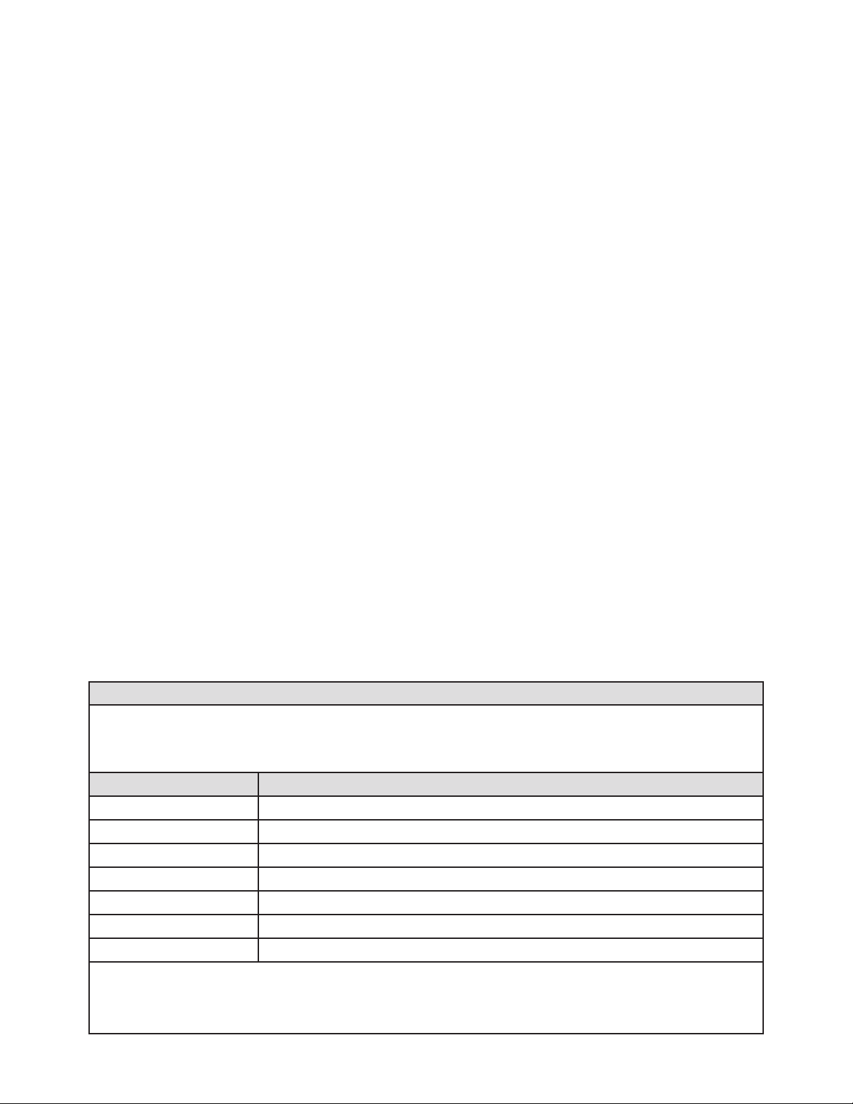
You may freely copy the table below for your personal use to help you program your console. Refer to Figure 22 for an example of a completed Fueling Point Table.
©2012 INCON 000-2044 Rev. B
 Loading...