

Page 1

TS-550evo & TS-5000evo Modbus Interface
Franklin Fueling Systems • 3760 Marsh Rd. • Madison, WI 53718 USA
Tel: +1 608 838 8786 • 800 225 9787 • Fax: +1 608 838 6433 • www.franklinfueling.com
Page 2

Contents
Important Safety Messages ................................................................................................. 3
Overview ................................................................................................................................ 4
Installation ............................................................................................................................. 4
Modbus RTU ................................................................................................................................. 4
Connecting a PC or Laptop Computer................................................................................4
Conguring IP Settings for Communication .................................................................................. 5
Obtain an IP Address Automatically .............................................................................................. 7
Check Status of Connection .......................................................................................................... 7
Network Parameters ...................................................................................................................... 8
Modbus Register Map...........................................................................................................9
Register Mapping Overview .......................................................................................................... 9
System Units ............................................................................................................................... 10
Tank Data ............................................................................................................................ 11
Manifold Data ......................................................................................................................12
Sensor Data ......................................................................................................................... 13
Mag Sensor Register Set ................................................................................................... 14
Relay Data ...........................................................................................................................14
Turbine Pump Interface (TPI) Data .................................................................................... 15
Input Data ............................................................................................................................15
Low Voltage Inputs Status Register ............................................................................................ 15
GIO Inputs Status Register ......................................................................................................... 16
Current Alarms Register Set .............................................................................................. 16
Alarm Code Table ........................................................................................................................ 16
2
Page 3
Important Safety Messages
FFS equipment is designed to be installed in association with volatile hydrocarbon liquids such as gasoline and diesel
fuel. Installing or working on this equipment means working in an environment in which these highly ammable liquids
may be present. Working in such a hazardous environment presents a risk of severe injury or death if these instructions
and standard industry practices are not followed. Read and follow all instructions thoroughly before installing or working
on this, or any other related, equipment.
As you read this guide, please be aware of the following symbols and their meanings:
This symbol identies a warning. A warning sign will appear in the text of this document when a
Warning
Caution
potentially hazardous situation may arise if the instructions that follow are not adhered to closely. A
potentially hazardous situation may involve the possibility of severe bodily harm or even death.
This is a caution symbol. A caution sign will appear in the text of this document when a potentially
hazardous environmental situation may arise if the instructions that follow are not adhered to closely.
A potentially hazardous environmental situation may involve the leakage of fuel from equipment that
could severely harm the environment.
Danger
Warning
This symbol identies an electrical danger. An electrical danger sign will appear in the text of this
document when a potentially hazardous situation involving large amounts of electricity may arise if
the instructions that follow are not adhered to closely. A potentially hazardous situation may involve
the possibility of electrocution, severe bodily harm, or even death.
Alarms and warnings are designed to alert you with specic details when a problem occurs so you
can take appropriate corrective action. System hardware failure warnings, tank related alarms, leak
detection sensor alarms, and line leak alarms can be custom programmed to do many things. The
events that require programming are denoted by a (p) below:
- Cause the red Alarm light or yellow Warning light to ash (standard)
- Activate / sound the console annunciator alarm horn (p)
- Activate internal output relays for external alarm devices (p)
-
Print alarm reports automatically, either locally (internal printer), or remotely (USB - HP compatible printer) (p)
- Send alarm and test reports to a specied e-mail address (p)
- Send reports to remote location(s), via internal data/fax modem (p)
Follow all applicable codes governing the installation and servicing of this product and the
entire system. Always lock out and tag electrical circuit breakers while installing or servicing
this equipment and any related equipment. A potentially lethal electrical shock hazard and the
possibility of an explosion or re from a spark can result if the electrical circuit breakers are
accidentally turned on during installation or servicing. Please refer to the Installation and Owner’s
Manual for this equipment, and the appropriate documentation for any other related equipment, for
complete installation and safety information.
Warning
Warning
Warning
Warning
Warning
Follow all federal, state and local laws governing the installation of this product and its associated
systems. When no other regulations apply, follow NFPA codes 30, 30A and 70 from the National Fire
Protection Association. Failure to follow these codes could result in severe injury, death, serious
property damage and/or environmental contamination.
Always secure the work area from moving vehicles. The equipment in this manual is usually
mounted underground, so reduced visibility puts service personnel working on this equipment in
danger from moving vehicles entering the work area. To help eliminate these unsafe conditions,
secure the area by using a service truck to block access to the work environment, or by using any
other reasonable means available to ensure the safety of service personnel.
When the Fuel Management System is used to monitor tanks containing gasoline or other
ammable substances, you may create an explosion hazard if you do not follow the requirements in
this manual carefully.
All wiring must enter the console’s enclosure through the designated knockouts. An explosion
hazard may result if other openings are used.
You must run wiring from probes or sensors to the Fuel Management System console in conduits
which are separate from all other wiring. Failure to do so will create an explosion hazard.
3
Page 4

This manual describes the installation and setup of the Modbus interface on the TS-550evo & TS-5000evo (evo). Included
are protocol descriptions, register mapping, and data descriptions for the data supported. This document is intended for
users who will be conguring the Modbus feature, and some understanding of Modbus protocol is required.
Overview
Modbus is a serial communication protocol that allows for simple system integration across various devices all on the
same network. This will allow the evo to be connected to a host system that supports Modbus TCP or RTU.
Modbus TCP is available via the evo’s Ethernet ports and Modbus RTU is available via Comm Port 1.
Installation
Modbus communication is a standard feature on the evo with software versions 2.3.0 or higher. It is available over the
standard Ethernet and RS-232 Comm Port 1. No additional hardware installation required. To use Modbus communication
you must connect to either the RS-232 or Ethernet port. For details on establishing these connections please refer to the
following manuals (000-2170 Installation Manual & 000-2173 Programming Manual).
Modbus RTU
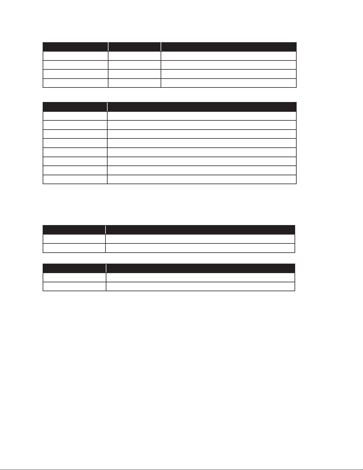
To setup the Modbus RTU format you will need to edit the Comm 1 serial port setting in the evo system parameters. First,
select the Mode Modbus and then dene the additional parameter as required for your conguration.
Group Name
Serial Ports
Parameter
Name
COMM 1
Description
Mode Network Connection (PPP)
Baud Rate 57600 1200 - 115200
Data Bits 8 7 or 8
Parity None
Stop Bits 1 1 or 2
Modbus Address 1 1 to 247
Default
Range of Values
Values
Network Connection (PPP)
Veeder-Root
Franklin Fueling System (XML)
Modbus
odd
even
none
Modbus TCP
Modbus TCP is enabled by default on Ethernet Port 502. Establish an Ethernet connection between the Master device
and the evo over port 502 to access the Modbus registers. Refer to the TS-550evo Programming Guide (000-2173) for
details regarding Ethernet connections to the systems.
Connecting a PC or Laptop Computer
To access the console using the Web Browser interface, connect a PC to the console through either the Ethernet port or
the COMM 1 serial port. If the console is connected to a local network, you can perform this setup from any PC on that
network by using a web browser, such as Microsoft’s Internet Explorer or Mozilla’s FireFox, or Safari for a Mac.
Note: The PC or laptop will recognize this serial connection as a network connection and will not allow the use of a Local
Area Connection simultaneously. While it is not necessary to disconnect the Local Area Connection to connect
using the Serial port, it will be necessary to disconnect the Serial Connection through the computers operating
system in order to use the Local Area Connection again.
The following instructions are written specically for Microsoft’s Windows 7 operating system. For assistance with other
operating systems, please contact Franklin Fueling Systems Technical Services.
Connecting a PC to the TS-550 evo Ethernet Port
1. Using an Ethernet Crossover, 10 Base-T cable, plug the RJ-45 connector on one end of the cable into the
Ethernet port of the console.
2. Plug the RJ-45 connector on the opposite end of the cable to the Network Interface Card of the computer.
3. Power up and log onto your PC.
Note:
You may need to re-congure your TCP / IP settings to allow the computer to communicate with the console.
Note: Some modern laptop computers have automatically switching Network Interface Cards and as such, will require the use
of a standard cat 6 cable instead of a crossover.
4
Page 5
Conguring IP Settings for Communication
Before attempting to modify any computer settings, contact
the Information Technologies department of your business,
if available. Some computer accounts may have restricted
permissions to overcome before any changes are allowed
to be made to TCP / IP settings.
At the PC:
1. Power up the PC and log into your Windows
operating system.
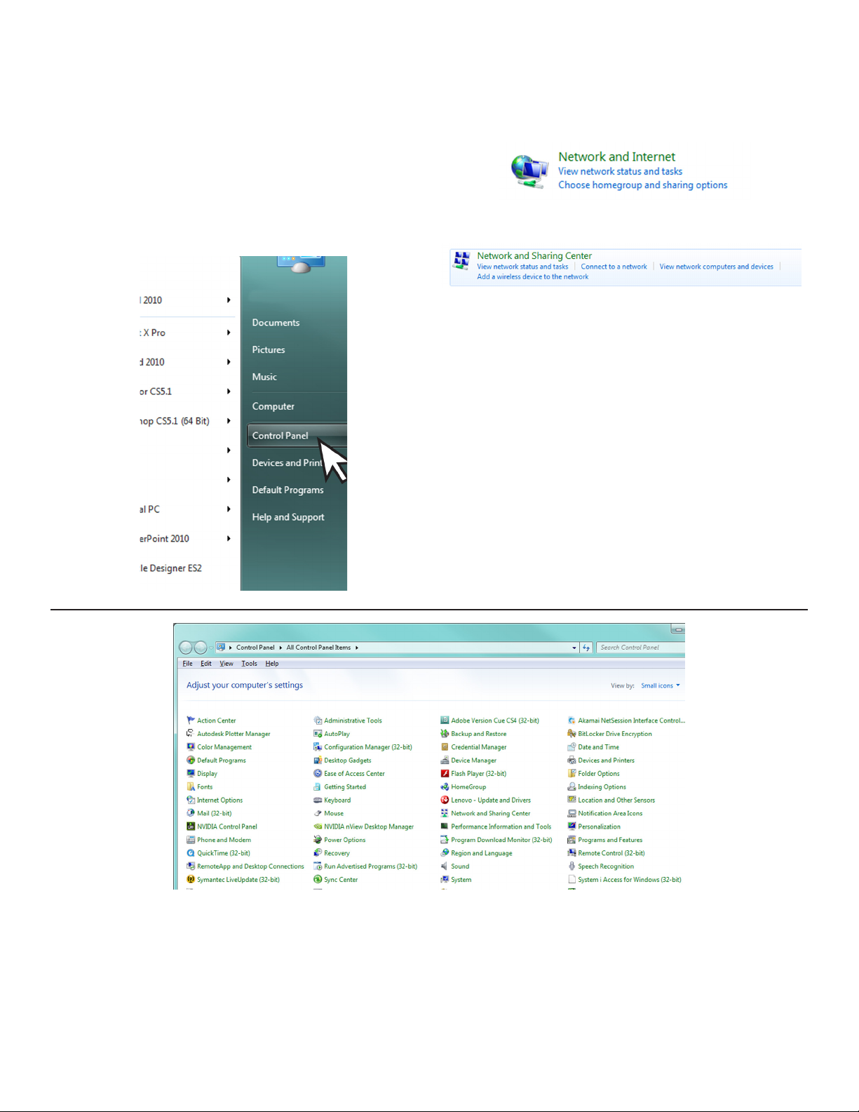
2. Click on Start, then select Control Panel.
3. There are (2) two views settings possible when
using Windows 7:
• In Category View, click on Network and Internet,
then click View Network Status and tasks under
Network and Sharing Center.
↓
• In Icon View, click on Network and Sharing
Center.
4. Click on the Change adapter settings in the left hand column.
5
Page 6
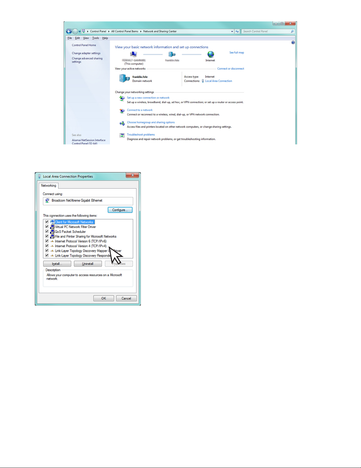
5. Right-click on Local Area Connection and select Properties.
6. In the Local Area Connection Properties dialog box, under “This connection uses the following items,” select
Internet Protocol Version 4(TCP / IPv4) and click Properties.
There are various ways to congure a computer to
communicate with a TS-550 evo console. These factors
depend upon the user’s computer knowledge and how the
computer is currently congured.
To determine which method is best for your site, read the
instructions in the following section carefully. Make detailed
notes on the current conguration of the TCP / IP settings on
the PC you are using. Read both the “Obtain an IP address
automatically” and the “Use the following IP address” methods
before making a choice between the two.
6
Page 7
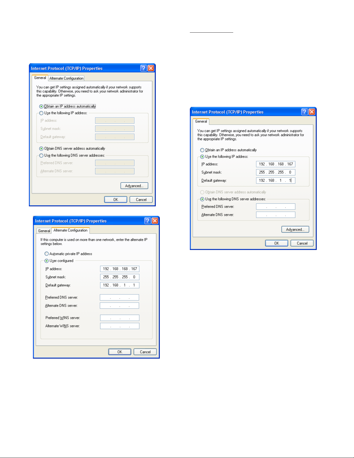
Obtain an IP Address Automatically
Computers commonly use this setting to obtain an IP
address automatically.
1. If Obtain an IP address automatically is
selected, it may be best to click the Alternate
Conguration tab.
Note: The consoles default IP address is
192.168.168.168. If the PC is normally congured
to acquire an IP address automatically, Alternate
Conguration may be used, as mentioned above, to
allow a connection to be enabled without the necessity
of reconguring the computer each time it will be used
to connect to this console.
Use the Following IP Address
1.
If Use the following IP address is selected and
the entry boxes contain any information, record this
information for use when console programming is
complete.
2. Select User Congured.
3. Enter an IP address. For simplicity, make the last
segment of the IP one number different than the IP
address of the console. Upon initial setup ONLY,
the numbers used in the gure may be used to
congure the TCP / IP settings of your PC. After
initial startup the programmed parameters should
be veried through the touchscreen
4. Leave all other information blank and click OK.
5. Close the Local Area network for changes to take
place.
2. Enter an IP address. For simplicity, make the last
segment of the IP one number different than the IP
address of the console. Upon initial setup ONLY,
the numbers used in the gure may be used to
congure the TCP / IP settings of your PC.
3. Leave the DNS information blank.
Note: The consoles default IP address is
192.168.168.168. If the PC is normally congured
to Use the following IP address, make sure that
all displayed information is recorded and kept prior
to making any changes. It may be necessary to use
this information to re-congure the console once
programming is complete.
Check Status of Connection
1. Check the status of your connection by going to
the Network Connections window.
2. If the connection status is disabled, enable it by
right-clicking on the Local Area Connection and
selecting Enable.
3. Verify link light is lit under Ethernet on Controller
module is lit and RX light is ashing.If technical
difculties arise, please contact Franklin Fueling
Systems Technical Support before proceeding.
7
Page 8

Network Parameters
To communicate with your network equipment (i.e. router,
switch, hub, etc.) you will need to modify the TS-550evo or
TS-5000evo console’s network parameters.
IP Address Settings:
IP Address – This is a logical (electronic) address, like a
street address, that the console uses to route
information. This address will have to match
your network, if connected to a network, in
order to ‘talk’ to a remote communication
device, or your PC.
Network Mask – Masking is a way to diversify the use
of multiple subnets. The mask must match
that of the network the console is connected
to. Masks are used in networking to create
‘sub-networks’ within a whole, like slicing and
apple. You have separate slices that may be
in different locations, but they are still from the
same apple. Administrators use this to make
separate networks, to maximize bandwidth or
capacity of medium resources (cables or ber).
Therefore, when your network uses static IP
addressing (assigned by an administrator),
this mask must match the Network Mask of the
router port that it is attached to. If the network
uses a DHCP server (automatically assigns
IP addresses) then the mask should meet the
specications set by your administrator.
Gateway – The Gateway is the logical address to the
nearest router port, commonly the one that
is connected to the console. Consult your
administrator for details on this and other
network parameters.
DNS Server Address:
Preferred DNS Server / Alternate DNS Server – The
domain name system (DNS) is the way that internet domain
names are located and translated into Internet Protocol
addresses. A domain name is a meaningful and easyto-remember tag for an internet address (used for e-mail
functions).
8
Page 9

Modbus Register Map
Register Values
Little Endian Ordering
All 32-bit values are stored such that the least signicant bits are in the lower of the 2 register addresses (a.k.a. Little
Endian). For example, Tank 1 Product level is stored in registers 204 and 205. If the value happened to be large enough
that it spanned 2 registers, say 9876.5 gallons, the values would be stored as follows:
Gallons resolution is 0.1, so the oating point value is multiplied by 10 and converted to the integer value 98765. In hex,
this value is 0x000181CD. Mapping this into registers:
Address 204: 0x81CD
Address 205: 0x0001
Two’s Complement Integer Representation
Negative values are stored as 2’s complement values. So, for the sake of a simple example let’s say we had -9876.5
gallons. The 2’s complement value of -98765 in hex is 0xFFFE7E33. By noting the highest bit is a 1, you know the
number is signed. To get the positive value you simply invert the bits and add 1, getting you back to 0x000181CD. This will
be set up in the Modbus client software.
The following is a table of Input Register addresses that can be accessed using function code 0x04.
Register Mapping Overview
Register Addresses Data Set Data Type
100-107 System Units System Unit Setting
200-235 Tank 1 Tank 1 Data
236-271 Tank 2 Tank 2 Data
272- …. Tank 3 … Tank 3 Data …
2756-2791 Tank 72 Tank 72 Data
2792-3199 Reserved
3200-3225 Manifold 1 Manifold 1 Data
3226-3251 Manifold 2 Manifold 2 Data
3252-…. Manifold 3… Manifold 3 Data…
4110-4135 Manifold 36 Manifold 36 Data
4136-4499 Reserved Reserved
4500-4501 2-Wire Sensor 1 2-Wire Sensor 1 Data
4502-4503 2-Wire Sensor 2 2-Wire Sensor 2 Data
4504-…. 2-Wire Sensor 3… 2-Wire Sensor 3 Data …
4642-4643 2-Wire Sensor 72 2-Wire Sensor 72 Data
4644-4799 Reserved Reserved
4800-4802 3-Wire Sensor 1 3-Wire Sensor 1 Data
4803-4805 3-Wire Sensor 2 3-Wire Sensor 2 Data
4804-…. 3-Wire Sensor 3... 3-Wire Sensor 3 Data …
4941-4943 3-Wire Sensor 48 3-Wire Sensor 48 Data
4944-4999 Reserved Reserved
5200-5206 Mag Sensor 1 Mag Sensor 1 Data
5207-5213 Mag Sensor 2 Mag Sensor 2 Data
5214-…. Mag Sensor 3… Mag Sensor 3 Data
5697-5703 Mag Sensor 72 Mag Sensor 72
5704-5899 Reserved Reserved
5900-5901 PS Relay 1 PS Relay 1 Status
5902-5903 PS Relay 2 PS Relay 2 Status
5904-5999 Reserved Reserved
9
Page 10

6000-6001 Relay 1 Relay 1 Status
6002-6003 Relay 2 Relay 2 Status
6003 -…. Relay 3… Relay 3 Status…
6166-6167 Relay 84 Relay 84 Status
6168-6399 Reserved Reserved
6400-6401 TPI 1 Controller 1 Status
6402-6403 TPI 2 Controller 2 Status
6404 -…. TPI 3 … Controller 3 Status …
6462-6463 TPI 32 Controller 32 Status
6464-6599 Reserved Reserved
6600-6601 LVI 1 Low Voltage Input 1 Status
6602-6603 LVI 2 Low Voltage Input 2 Status
6604-6699 Reserved Reserved
6700-6701 AC Input 1 AC Input 1Status
6702-6703 AC Input 2 AC Input 2 Status
6704-…. AC Input 3… AC Input 3 Status …
6842-6843 AC Input 72 AC Input 72 Status
6844-7099 Reserved Reserved
7100-7101 GIO 1 IO Input 1 Status
7102-7103 GIO 2 IO Input 2 Status
7104-…. GIO 3… IO Input 3 Status
7194-7195 GIO 48 IO Input 48 Status
7196-7399 Reserved Reserved
7400-7404 Current Alarms 1
7405-7409 Current Alarms 2
…
7645-7649 Current Alarms 50
7650-9999 Reserved Reserved
System Units
Units Data Register Set
Address Offset Unit Type Data Type
5-7 Reserved NA
Length Units Table
Register Value Unit Type Units Precision
10
0 Length See Length Units Table
1 Volume See Volume Units Table
2 Temperature See Temperature Units Table
3 Density See Density Units Table
4 Mass See Mass Units Table
0 Millimeters 1 mm
1 Centimeters 0.1 cm
2 Meters 0.001 m
3 Inches 0.1 in
Page 11

Volume Units Table
Register Value Unit Type Units Precision
0 Liters 0.1 L
1 Gallons 0.1 gal
2 Imperial Gallons 0.1 imp gal
Temperature Units Table
Register Value Unit Type Units Precision
0 Centigrade 0.1 C
1 Fahrenheit 0.1 F
Density Units Table
Register Value Unit Type Units Precision
0 Kilograms per cubic meter 0.1 kg/m^3
1 Grams per cubic centimeter 1 g/cm^3
2 Pounds per cubic foot 0.001 lbs/ft^3
Mass Units Table
Register Value Unit Type Units Precision
0 Kilograms 0.1 kg
1 Grams 1 g
2 Pounds 0.01 lbs
Tank Data
Tank Data Register Set
Tank Register Start Address = (TankNumber-1)*36+200
Register Description Address Offset Data Format Resolution
Tank Status Register 0, 1 See Tank Status Register
Tank Alarms Register* 2,3 See Tank Alarms Register
Product Level 4,5 Signed 32-bit Integer See Length Units
Water Level 6,7 Signed 32-bit Integer See Length Units
Temperature 8,9 Signed 32-bit Integer See Volume Units
Gross Product Volume 10,11 Signed 32-bit Integer See Volume Units
Net Product Volume 12,13 Signed 32-bit Integer See Volume Units
Water Volume 14,15 Signed 32-bit Integer See Volume Units
Ullage Volume 16,17 Signed 32-bit Integer See Volume Units
Density 18,19 Signed 32-bit Integer See Density Units
Net Density 20,21 Signed 32-bit Integer See Density Units
Mass 22,23 Signed 32-bit Integer See Mass Units
Reserved 24-31 N/A
*Note that this register does not contain all possible alarms for a tank.
Tank Status Register
Bit # Status Bit
0 Tank in Alarm
1 Delivery in Progress
2 Static Tank Test in Progress
3-31 Reserved
11
Page 12

Tank Alarms Register
Bit # Status Bit
0 High High Product
1 High Product
2 High Water
3 Low Product
4 Low Low Product
5 Precision Leak Detected
6 Gross Leak Detected
7 SCALD Leak Detected
8 Product Density High Limit Exceeded
9 Product Density Low Limit Exceeded
10 Float Missing
11 Probe Synchronization Error
12 No Probe Detected
13 Float Height Error
14-31 Reserved
Manifold Data
Manifold Data Register Set
Manifold Register Start Address = (ManifoldNumber-1)*26+3200
Register Description Address Offset Data Format Resolution
Manifold Status Register 0, 1 See Manifold Status Register
Manifold Alarms Register* 2,3 See Manifold Alarms Register
Temperature 4,5 Signed 32-bit Integer See Volume Units
Gross Product Volume 6,7 Signed 32-bit Integer See Volume Units
Net Product Volume 8,9 Signed 32-bit Integer See Volume Units
Water Volume 10,11 Signed 32-bit Integer See Volume Units
Ullage Volume 12,13 Signed 32-bit Integer See Volume Units
Reserved 14-20 N/A
*Note that this register does not contain all possible alarms for a tank.
Manifold Status Register
Bit # Status Bit
0 Manifold in Alarm
1 Delivery in Progress
2-31 Reserved
Manifold Alarms Register
Bit # Status Bit
0 Low Product
1 Low Low Product
2 SCALD Leak Detected
3-31 Reserved
12
Page 13

Sensor Data
2-Wire Sensor Status Register
2-Wire Sensors Start Address = (SensorNumber-1)*2+4500
Bit # Status Bit
0 Sensor State
1-31 Reserved
2-Wire Sensor State Table
Bit Value Sensor State
0 Ok
1 Alarm
3-Wire Sensor Register Set
3-Wire Sensors Start Address = (SensorNumber-1)*3+4800
Register Description Address Offset Data Format
Sensor Type 0 See 3-Wire Sensor Type Table
Sensor State 1 See 3-Wire Sensor State Table
Reserved 2
3-Wire Sensor Type Table
Register Value Sensor Type
0 Unknown Sensor
1 Interstitial (EIS) OR 2-Wire Sensor
2 Discriminating Interstitial Sensor (DIS)
3 Discriminating Dispenser Sump Sensor (DDS)
4 Discriminating Turbine Sump Sensor (DTS)
5 Monitoring Well Sensor (MWS)
6 Hydrostatic Interstitial Brine Reservoir Sensor (HIS)
7 Discriminating Monitoring Well Vapor Sensor (DVS)
3-Wire Sensor State Table
Register Value Sensor State
0 Ok
1 Alarm
2 Sensor On
3 Product Detected
4 Water Detected
5 Sump Full
6 Dry Well
7 High Brine
8 Low Brine
9 Vapor Detected
10 Vapor Sensor Malfunctioning
11 Temperature Error
12 Synchronization Error
13 Signal Lost
14 ID Error
15 Data Error
13
Page 14
Mag Sensor Register Set
Mag Sensors Start Address = (SensorNumber-1)*7+5200
Register Description Address Offset Data Format
Product Level 0,1 Signed Integer (See Length Units)
Water Level 2,3 Signed Integer (See Length Units)
Status Register 4 See Mag Sensor Status Register
Reserved 5-8
Mag Sensor Status Register
Bit # Status Bit
0 Water Warning Active
1 Water Alarm Active
2 Product Alarm Active
3 Installation Alarm Active
4 Sensor Missing Alarm Active
5 Sensor Sync Alarm Active
6 Sensor Float Missing Active
7-15 Reserved
Relay Data
Relay Status Register
PS Relay Start Address = (PSRelay-1)*2+5900
Relay Start Address = (Relay-1)*2+6000
Bit # Status Bit
0 Relay Status
1-15 Reserved
Relay Status State Table
Bit Value Relay State
0 Deactivated
1 Active
14
Page 15

Turbine Pump Interface (TPI) Data
TPI Controller Status Register
TPI Start Address = (TPINum-1)*2+6400
Bit # Status Bit
0 Pump Status
1 Pump Forced Off
2 Pump Controller Faulted
3-15 Reserved
Pump Status Table
Register Value Pump Status State
0 Idle
1 Running
Pump Forced Off State Table
Register Value Pump Forced Off State
0 Ok
1 Force Off
Pump Controller Faulted Table
Register Value Pump Controller Faulted State
0 Ok
1 Controller Faulted
Input Data
Low Voltage Inputs Status Register
LVI Start Address = (LVINum-1)*2+6600
Bit # Status Bit
0 Input Status
1-15 Reserved
Low Voltage Input Status Table
Bit Value Low Voltage Input State
0 In-Active
1 Active
AC Input Status Register
DHI Start Address = (DHI Num-1)*2+6700
Bit # Status Bit
0 Input On
1-15 Reserved
AC Input Bit Value Table
Register Value AC Input State
0 In-Active
1 Active
15
Page 16

GIO Inputs Status Register
GIO Start Address = (GIO Num-1)*2+7100
Bit # Status Bit
0 Input On
1-15 Reserved
GIO Input Bit Value Table
Register Value GIO Input State
0 In-Active
1 Active
Current Alarms Register Set
Alarms Start Address = (Alarm Num-1)*5+7400
Register Description Address Offset Data Format
Alarm Code 0 See Alarm Code Table
Alarm Data 1 Integer, typically device number
Reserved 2-5
Alarm Code Table
Alarm Code Device Type Alarm Name
-2 None Unknown
-1 None Any
0 None No error
1 Slot Test Alarm
SYSTEM ALARMS (0900-1999)
1001 None Probe module number mismatch
1002 None Probe module number mismatch
1003 None 4-20mA module number mismatch
1004 None Relay module number mismatch
1005 None AC Input module number mismatch
1006 None 4-20mA module number mismatch
1007 None 4-20mA module number mismatch
1008 None 2-Wire Sensor module number mismatch
1009 None 3-Wire Sensor module number mismatch
1010 None Power Supply module number mismatch
1011 None IO module number mismatch
1012 None DIM module number mismatch
1013 None LON module number mismatch
1014 None Printer module number mismatch
1015 None Console DTU number mismatch
1018 None IS Barrier Violation
1022 Slot Console DTU is ofine
1023 Slot Probe module is ofine
1024 Slot 4-20mA module is ofine
1025 Slot Relay module is ofine
1026 Slot AC Input module is ofine
1027 Slot 2-Wire Sensor module is ofine
16
Page 17

1028 Slot 3-Wire Sensor module is ofine
1029 Slot Power Supply module is ofine
1030 Slot IO module is ofine
1031 Slot Controller module is ofine
1032 None System Bus Error
1033 None Power Supply Setup Error
1034 None AC Input Setup Error
1035 None Relay Module Setup Error
1036 None Probe Module Setup Error
1037 None 4-20mA Module Setup Error
1038 None 2-Wire Sensor Module Setup Error
1039 None 3-Wire Sensor Module Setup Error
1040 None Vapor Recovery Monitor Setup Error
1041 None Fuel Management System Setup Error
1042 None Secondary Containment Monitor Setup Error
1043 None System Setup Error
1044 None Invalid Registration
1045 None Invalid Conguration
1046 None Internal Error #1 - contact technical support
1047 None Auto Detect Setup Error
1048 None Set Date and Time
VAPOR RECOVERY MONITORING ALARMS (2000-2499)
2001 aldHose Daily Vapor Collection Warning
2002 aldHose Daily Vapor Collection Failure
2003 aldHose Weekly Vapor Collection Warning
2004 aldHose Weekly Vapor Collection Failure
2005 aldHose ORVR Vehicle Limit Reached
2040 aldChannelPRB VFM Missing
2041 aldChannelPRB VFM Error
2042 aldChannelPRB VFM No Data
2050 None Weekly Ullage Pressure Warning
2051 None Weekly Ullage Pressure Failure
2053 None Weekly Ullage Pressure Leak Test Warning
2054 None Weekly Ullage Pressure Leak Test Failure
2056 None Ullage Volume Insufcient
2057 None Pressure Out of Range for Ullage Pressure Leak Test
2058 None Monthly Ullage Pressure Warning
2059 None Monthly Ullage Pressure Failure
2070 None Pressure Sensor Error
2071 None Pressure Sensor Open Circuit
2080 None Vapor Processor Input
2081 None Vapor Processor Failure
2082 None Vapor Processor Warning
2083 None Vapor Processor Failure
2090 None Conguration Error
2091 None TS-DIM Read Data Error
2092 None External ATG Connection Down Error
17
Page 18

2093 None TS-DIM Connection Down
2095 None Development Test Alarm
2096 None External ATG Connection Down Warning
FUEL MANAGEMENT SYSTEM ALARMS (2500-2999)
2500 None FMS conguration error
2501 Tank No data available
2502 Tank Float missing
2503 Tank Probe synchronization error
2504 Tank No probe detected
2505 Tank Temperature Error
2506 Tank RTD table error
2507 Tank API volume correction error
2508 Tank Alpha volume correction error
2509 Tank Level error
2510 Tank Product volume error
2511 Tank Water volume error
2512 Tank Ullage error
2513 Tank Correction table error
2514 Tank Net error
2515 Tank Low battery
2516 Tank System memory error
2517 Tank Float height error
2519 Tank Line monitor disabled
2520 Tank Open analog input
2521 Tank Unstable probe
2522 Tank High high product level
2523 Tank High product level
2524 Tank High water level
2525 Tank Low product volume
2526 Tank Low low product volume
2527 Manifold Manifold Low product volume
2528 Manifold Manifold Low low product volume
2529 Tank High product volume
2530 Tank High High product volume
2540 Tank Density error
2541 Tank High water/Phase sep
2650 Tank Tank Theft Detected
2651 Manifold Manifold Theft Detected
2652 Tank Tank Leak Detected
2653 Manifold Manifold Leak Detected
2654 Tank Tank Gross Leak Detected
2655 Manifold Manifold Gross Leak Detected
2656 Tank Tank Scald Leak Detected
2657 Manifold Manifold Scald Leak Detected
2658 Tank Tank Scald Compliance Warning
2659 Manifold Manifold Scald Compliance Warning
18
Page 19

2660 Tank Tank Water/Phase Sep Float Disabled
2680 Tank Tank Product Density High Limit Exceeded
2681 Tank Tank Product Density Low Limit Exceeded
2682 Tank Density oat error
2690 Mag Sensor Mag sensor conguration error
2691 Mag Sensor Mag sensor not learned error
2692 Mag Sensor Mag sensor oat missing
2693 Mag Sensor Mag sensor synchronization error
2694 Mag Sensor Mag sensor missing
2695 Mag Sensor Mag sensor data error
2696 Mag Sensor Mag sensor oat height error
2697 Mag Sensor Mag installation error
2698 Mag Sensor Mag water warning
2699 Mag Sensor Mag water alarm
2700 Mag Sensor Mag product alarm
SECONDARY CONTAINMENT MONITORING ALARMS (3000-3499)
3000 Containment Vacuum Too High
3001 Containment Low Vacuum
3002 Containment Failed to Reach Target Vacuum
3003 Containment Failed to Hold Vacuum
3004 Containment Unstable Vacuum
3005 Containment Containment Not Learned
3006 Containment Vacuum Sensor Failed
3007 Containment Vacuum Sensor Failed/Not Connected
3008 Containment Containment Pump Request Ignored
3009 Containment Low Vacuum And Pump Request Ignored
3010 None Containment Program Error Warning
3011 None Containment Program Error Detected
3012 Containment Not Congured
3013 Containment Disabled
ANA ALARMS (3500-3599)
3500 4-20mA Channel 4-20mA Input Error
SENSOR ALARMS (3600-3699)
3600 2-Wire Sensor SN2 Sensor On
3601 Slot SN2 Fuse Blown
3602 3-Wire Sensor SN3 Sensor On
3603 Slot SN3 Fuse Blown
3604 Slot SN3 Pwr Short
3605 3-Wire Sensor SN3 Data Error
3606 3-Wire Sensor SN3 Water
3607 3-Wire Sensor SN3 Product
3608 3-Wire Sensor SN3 Sump Full
3609 3-Wire Sensor SN3 Dry Well
3610 3-Wire Sensor SN3 High Brine
3611 3-Wire Sensor SN3 Low Brine
3612 3-Wire Sensor SN3 Vapor
3613 3-Wire Sensor SN3 No Signal
19
Page 20

20
3614 3-Wire Sensor SN3 Id Error
3615 3-Wire Sensor SN3 Sync Error
LINE LEAK DETECTION ALARMS (3700-3799)
3700 Line Gross Leak Test Failed
3701 Line Monthly Leak Test Failed
3702 Line Precision Leak Test Failed
3703 Line Failed to Pressure Up
3704 Line Failed to Catch Pressure
3705 Line Sudden Pressure Loss
3706 Line Dispensing Pressure Test Failed
3707 Line High Line Pressure
3708 Line Extended Hook Signal
3709 4-20mA Channel Pressure Transducer Fail
3710 Line Line is not congured
3711 Line Line Program Error Detected
3712 Line Air in Line
3713 Line Line Not Enabled
3714 Line Line Not Learned
3715 Line 3 GPH Compliance Expired
3716 Line 0.2 GPH Compliance Expired
3717 Line 0.1 GPH Compliance Expired
3718 Line Marginal Pass of Gross Leak Test
3719 Line Line Pump Request Ignored
PRINTER ALARMS (3800-3899)
3800 System Printer Paper Jam
3801 System Printer Paper Jam
3802 System Printer Solenoid Stuck
3803 System Printer Solenoid Stuck
3804 None Printer Door Open
3805 None Check Printer
3806 None Printer Motor Temperature
3807 None Printer Head Temperature
3808 None Check Paper
MODEM ALARMS (3900-3999)
3900 None Modem Error
3901 None Cellular Modem Error
3902 None Dynamic DNS Error
VR EMULATION ALARMS (4000-4049)
4000 None VR Dim Data Lost
DISPENSER INTERFACE MODULE ENGINE ALARMS (4050-4099)
4050 None Dim Communications Failure
TURBINE PUMP INTERFACE ALARMS (4100-4199)
4100 None Communication Failure
4101 Pump Pump Communication Fail
4102 Pump Clogged Intake
4103 Pump Dry Tank
4104 Pump Pump In Water
Page 21

4105 Pump Under Voltage
4106 Pump Locked Rotor
4107 Pump Open Circuit
4108 Pump Capacitor Failing
4109 Pump Short Circuit
4110 Pump High Temperature
4111 Pump Not Calibrated
4112 Pump Extended Run
4113 Pump Relay Fault
4114 Pump L2 Open
4115 Pump Over Voltage
4116 Pump Unbalanced Voltage
4117 Pump Unbalanced Load
4118 Pump Unknown Fault
4119 Pump Underload
4120 Pump Over Speed
4121 Pump Long Flash
4122 Pump Hardware Fault
4123 Pump Controller Type Error
INPUT ALARMS (4200-4299)
4200 GIO Input IO Input Alarm
4201 PS Input Power Supply Input Alarm
4202 DHI Input AC Input Alarm
PLC ALARMS (4300-4399)
4300 None DTU FFS Interference
4301 None DTU Non FFS Interference
4302 PLC Remote DTU is ofine
COMPLIANCE ALARMS (4400-4499)
4401 Tank Monthly Compliance Alarm
4402 Tank Monthly Compliance Warning
4403 Tank Annual Compliance Alarm
4404 Tank Annual Compliance Warning
4405 Manifold Monthly Compliance Alarm
4406 Manifold Monthly Compliance Warning
4407 Line Monthly Compliance Alarm
4408 Line Monthly Compliance Warning
4409 Line Annual Compliance Alarm
4410 Line Annual Compliance Warning
4411 2-Wire Sensor Monthly Compliance Alarm
4412 2-Wire Sensor Monthly Compliance Warning
4413 3-Wire Sensor Monthly Compliance Alarm
4414 3-Wire Sensor Monthly Compliance Warning
4415 Mag Sensor Monthly Compliance Alarm
4416 Mag Sensor Monthly Compliance Warning
21
Page 22

©2013 FFS 000-0536 Rev A
 Loading...