

Page 1
Tank Sentinel Operator’s Guide
®
TS-1001, 2002, 504, 508 & 750
Automatic Tank Gauge/ Leak Detection System
3760 Marsh Road ● Madison, WI 53718 U.S.A.
Tel: +1 608 838 8786 ● Fax: +1 608 838 6433 ● www.franklinfueling.com
Tel: USA & Canada 1 800 225 9787 ● Tel: Mexico 001 800 738 7610
Part Number: 000-1052, Rev. D
©
Copyright
August 2011
Page FC - 1
Page 2
NOTICE
Franklin Fueling Systems has strived to produce the nest possible manual for you, and to ensure
that the information contained in it is complete and accurate. However, Franklin Fueling Systems
makes no expressed or implied warranty with regard to its contents. Franklin Fueling Systems
assumes no liability for errors or omissions, or for any damages, direct or
consequential, that result from the use of this document or the equipment which
it describes.
This document contains proprietary information and is protected by copyright. All
rights are reserved. No part of this document may be reproduced in any form
without the prior written consent of Franklin Fueling Systems.
Franklin Fueling Systems reserves the right to change this document at any time without notice.
Need Help ? Contact Franklin Fueling Systems at:
Franlin Fueling Systems
3760 Marsh Road
Madison, WI 53718
Office Hours: 7 a.m. to 7 p.m. Central Time Monday through Friday
- ecivreS lacinhceT
Phone: (608) 838-8786
Fax: (608) 838-6433
Visit our Website at:
Phone: (800) 984-6266
E-mail:
techserve@franklinfueling.com
www.franklinfueling.com
INCON is a wholly owned subsidiary of Franklin Electric and is a member of the
Franklin Fueling Systems Group
Tank Sentinel ® SCALD® Brite BriteBox® Britebus® BriteSensors
and INCON® are registered trademarks of Intelligent Controls, Inc.
System Sentinel™ and System Sentinel
™ are trademarks of
Intelligent Controls, Inc.
Copyrighted 1997, 1998, 2003, 2011 Intelligent Controls, Inc. All rights reserved.
®
—
Tank Sentinel Setup Programming Guide
—
Page 3

T able of Contents
P Preface................................................................................................... P - i
Graphic Symbol Conventions ............................................................................... P - i
Page Numbering Conv ention – Example:....................................................... P - i
Page Layout Convention – Example: .............................................................. P - i
Product Overview ................................................................................................. P - ii
Alarms and Warnings...................................................................................... P - iii
Tank Sentinel® Features...................................................................................... P - iii
Safety .................................................................................................................. P - iv
Approvals ...................................................................................................... P - iv
Need Help ? – Names and Phone Numbers to Contact.......................... P - iv
1 Console – Basic Operation .................................................................. 1 - 1
General.................................................................................................................. 1 - 1
Operating Modes................................................................................................... 1 - 1
Console Component Location ............................................................................... 1 - 2
Display .................................................................................................................. 1 - 2
Run Mode Display ........................................................................................... 1 - 2
Sentinel Mode Display..................................................................................... 1 - 3
Tank or Line Testing Display ........................................................................... 1 - 3
Tank & Line Display Notes: .......................................................... 1 - 3
Menu keys (M1 thru M4) ....................................................................................... 1 - 3
Status Row (with Alarm Test Key) ......................................................................... 1 - 4
Keypad Keys ......................................................................................................... 1 - 4
Report Printer........................................................................................................ 1 - 4
Paper Advance Button .......................................................................................... 1 - 4
RS232 Communication Ports ................................................................................ 1 - 4
TS-FM2 Receptacle .............................................................................................. 1 - 5
Model & Serial Number Label................................................................................ 1 - 5
Product & Tank Related Keys................................................................................ 1 - 5
Menu Related Keys ............................................................................................... 1 - 6
Changing the Display and Report Language ............................................... 1 - 8
Special Keys ......................................................................................................... 1 - 9
Selecting A Report .......................................................................................... 1 - 9
Report Features ............................................................................................ 1 - 10
Check Date &Time ..................................................................................... 1 - 10
Check Display, Printer, or Dialtone .......................................................... 1 - 10
Check Software & Hardware Options ........................................................ 1 - 10
Starting a tank or Line Leak Test: ............................................................ 1 - 11
Testing Note:............................................................................................ 1 - 11
Showing the Status of Tank or Line Leak Tests ....................................... 1 - 11
Indications of Active Tests:...................................................................... 1 - 11
Aborting a Tank or Line Leak Test............................................................ 1 - 12
ACK Shift key uses: .................................................................................... 1 - 13
Upgrade Menu..................................................................................................... 1 - 14
Sample Upgrade Instructions .............................................................................. 1 - 16
Table of Contents Page TOC - 1
TOC
Page 4

2 Acknowledging Alarms ........................................................................ 2 - 1
Purpose of Audio / Visual Alarms.......................................................................... 2 - 1
Audio Alarm Annunciator (& Output Relays)......................................................... 2 - 1
Visual Alarm Indications ........................................................................................ 2 - 2
Alarm Types........................................................................................................... 2 - 3
System Warnings ............................................................................................ 2 - 3
Tank Alarms..................................................................................................... 2 - 3
Sensor Alarms................................................................................................. 2 - 3
Line Alarms...................................................................................................... 2 - 3
Alarm Status.......................................................................................................... 2 - 3
Acknowledge Password........................................................................................ 2 - 4
Acknowledging Alarms / Silencing Alarms ............................................................ 2 - 4
Starting a Grace Period................................................................................... 2 - 4
Leak Detection Sensors .................................................................................. 2 - 5
3 T ank Sentinel Reports.......................................................................... 3 - 1
Reports Overview................................................................................................. 3 - 1
Report Types......................................................................................................... 3 - 1
How to Print a Report...................................................................................... 3 - 2
FAXing a Report .............................................................................................. 3 - 2
Where are Fax’d Reports Sent ? ............................................................... 3 - 2
Example – Automatic Alarm Reports .............................................................. 3 - 3
Typical Information Shown On Reports..................................................... 3 - 3
Product Inventory Detail REPORT ................................................................. 3 - 4
Product Inventory Summary REPORT ........................................................... 3 - 4
Tank Inventory Detail REPORT ...................................................................... 3 - 5
Tank Inventory Summary REPORT................................................................ 3 - 5
Product Delivery Detail REPORT ................................................................... 3 - 6
Product Delivery Summary REPORT............................................................. 3 - 6
Product Delivery History REPORT................................................................. 3 - 6
Product Usage Detail REPORT..................................................................... 3 - 7
Product Usage Summary REPORT ............................................................... 3 - 7
Product Usage Reconcile REPORT ............................................................... 3 - 8
Product Usage Sales REPORT...................................................................... 3 - 9
Tank Leak Test Estimate REPORT ............................................................... 3 - 10
Standard (Static) Tank Leak Test REPORT .................................................. 3 - 11
Slope & Leak Test Results ............................................................................ 3 - 11
SCALD Leak Test REPORT....................................................................... 3 - 12
Line Compliance Test REPORT .................................................................... 3 - 13
Line Leak T est REPORT ............................................................................... 3 - 14
Line Leak Diagnostic REPORT..................................................................... 3 - 14
Line Leak Test History REPORT................................................................... 3 - 15
Report(s) Sent to Remote Fax Machines:............................................... 3 - 16
Sensor Status REPORT ............................................................................... 3 - 17
V apor Sensor REPORT ................................................................................ 3 - 17
Alarm Reports ............................................................................................... 3 - 18
Active System Alarms REPORT .................................................................. 3 - 18
Cleared System Alarms REPORT................................................................ 3 - 18
System Alarm History REPORT................................................................... 3 - 18
Active Tank Alarms REPORT ....................................................................... 3 - 18
TOC
Page TOC - 2 Tank Sentinel Operator’s Guide
Page 5

Cleared Tank Alarms REPORT..................................................................... 3 - 18
Tank Alarm History REPORT ....................................................................... 3 - 18
Active Sensor REPORT ............................................................................... 3 - 19
Cleared Sensor Alarms REPORT................................................................. 3 - 19
Sensor Alarm History REPORT .................................................................... 3 - 19
Active Line Alarms REPORT ........................................................................ 3 - 19
Cleared Line Alarms REPORT...................................................................... 3 - 19
Line Alarm History REPORT ........................................................................ 3 - 19
All Active Alarms REPORT........................................................................... 3 - 20
All Cleared Alarms REPORT ....................................................................... 3 - 20
All Alarm History REPORT ........................................................................... 3 - 21
Changing the Number of Alarms to Print ....................................................... 3 - 21
System Setup REPORT ............................................................................... 3 - 22
Tank Setup REPORT .................................................................................... 3 - 22
Setup Report example............................................................................. 3 - 23
Regulatory REPORT..................................................................................... 3 - 27
CPM Alarm REPORT.................................................................................... 3 - 28
CPM Status REPORT................................................................................... 3 - 28
CPM Monthly REPORT ................................................................................ 3 - 29
Generator Run REPORT .............................................................................. 3 - 30
Print Test REPORT ....................................................................................... 3 - 30
4 Leak Testing.......................................................................................... 4 - 1
Overview............................................................................................................... 4 - 1
Tank Leak Tests – Type and Frequency ................................................................ 4 - 2
Before Starting a Standard (static) Tank Leak Test ......................................... 4 - 2
When to Run Tank Leak Tests......................................................................... 4 - 2
Starting Tank Leak Tests: ................................................................................ 4 - 3
Tank Leak Test Results ................................................................................... 4 - 3
Reasons Why Tank Leak Tests Fail:................................................................ 4 - 3
When a Leak Test Fails.................................................................................... 4 - 4
TS-LLD Line Leak Tests: ....................................................................................... 4 - 5
Type and Frequency.............................................................................................. 4 - 5
Before Starting a Line Leak Test:..................................................................... 4 - 5
When to Run Line Leak Tests.......................................................................... 4 - 5
Starting Line Leak Tests .................................................................................. 4 - 6
When a Line Leak Test Fails / Line Leak is Detected ...................................... 4 - 6
Steps to take When a Line Leak is Detected:........................................................ 4 - 7
Need help ? ........................................................................................................... 4 - 7
5 T roubleShooting & Routine Maintenance ........................................... 5 - 1
TroubleShooting..................................................................................................... 5 - 1
Site Policy:............................................................................................................. 5 - 8
• Silencing Alarms ........................................................................................... 5 - 8
• Acknowledging Alarms.................................................................................. 5 - 8
• Grace Periods (Allowed when, number of times, etc.) .................................. 5 - 8
• Troubleshooting Alarms & Error Messages ................................................... 5 - 9
• Line and Tank Leak Test Failures................................................................. 5 - 10
• Call Numbers for Help................................................................................. 5 - 11
Site Sketch / paste-in area: ................................................................................. 5 - 12
Table of Contents Page TOC - 3
TOC
Page 6

Routine Maintenance........................................................................................... 5 - 14
• External Cleaning ..................................................................................... 5 - 14
• Replacing the Printer P aper Roll............................................................... 5 - 14
• Lubricate Printer: ...................................................................................... 5 - 14
• Replacing Fuses, Memory-backup Battery , & Interior Cleaning:.............. 5 - 15
FCC Information & Requirements ........................................................ FCC - 1
Overall Information & Requirements ................................................................ FCC - 1
INDUSTRY CANADA Information & Requirements ...................................... FCC - 2
CP-01 Issue 8, Part I, Section 14.1.................................................................. FCC - 2
CP-01, Issue 8, Part I, Section 14.2................................................................. FCC - 2
G Glossary .............................................................................................. G - 1
CFF Customer Feedback Form....................................................... CFF - 1
W Warranty .............................................................................................. W - 1
T able of FIGURES and T ABLES
Graphic Symbol Conventions .................................................................... P - i
Page Numbering Convention – Example:................................................. P - i
Page Layout Convention – Example: ........................................................ P - i
Figure P - 1 TS-1001 & TS-2001 Model ATG Consoles......................... P - iii
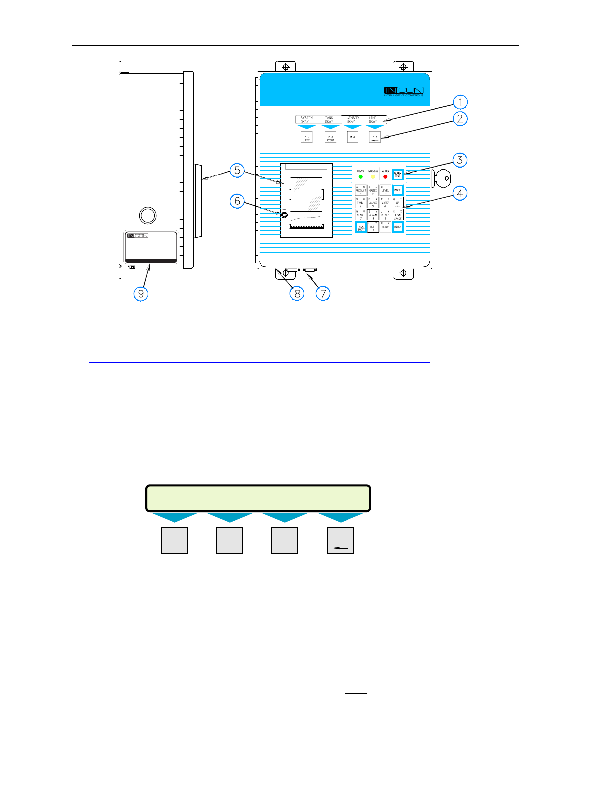
Figure 1 - 1 Console Component Identification...................................... 1 - 2
TABLE 2.1 Output Groups (A — FF)..................................................... 2 - 6
Figure 2.1 External BriteBoxes to Console ......................................... 2 - 7
Figure 2.2 Typical Station Partial Side-view with One Tank................. 2 - 7
TABLE 2.1 Output Groups (A — FF)..................................................... 2 - 8
Setup Report (example) .......................................................................... 3 - 23
TABLE 5 - 1 Alarms & Error messages ................................................ 5 - 1
TABLE 5 - 2 SYSTEM TEST SCHEDULE ............................................ 5 - 7
TABLE 5 - 3 Fax Numbers & Location (Fill-in)....................................... 5 - 11
TOC
—
Page TOC - 4 Tank Sentinel Operator’s Guide
❖
—
Page 7
P PREF ACE
Contents:
Graphic Symbol, Page Numbering
and Layout Conventions
Product Overview
Alarms and Warnings
Graphic Symbol Conventions
NOTE
Important information, tips, and hints are highlighted by the NOTE graphic.
☞
CAUTION
WARNING
DANGER
must be followed.
— ❖ — End of Chapter (or Section) symbol
or
messages are highlighted by this graphic.
messages are highlighted by this graphic and contain instructions that
Tank Sentinel Features
Safety
Approvals
Need Help ? Names and Phone Numbers to
Contact
Page Numbering Convention – Example:
•
Page 2 - 1 = Chapter 2 page 1• Page 6.1 - 2 = Chapter 6 . Section 1 – Page 2
Page Layout Convention – Example:
Manual Name
EVEN NUMBERED
(
PAGES
)
Page Number
Chapter Number
Chapter Number &
Name (
FIRST
Chapter Contents
TOP LEFT
PAGE
)
Chapter Name
(
ODD NUMBERED
PAGES
)
Page Number
Chapter Number
PREFACE Page P - i P
Page 8
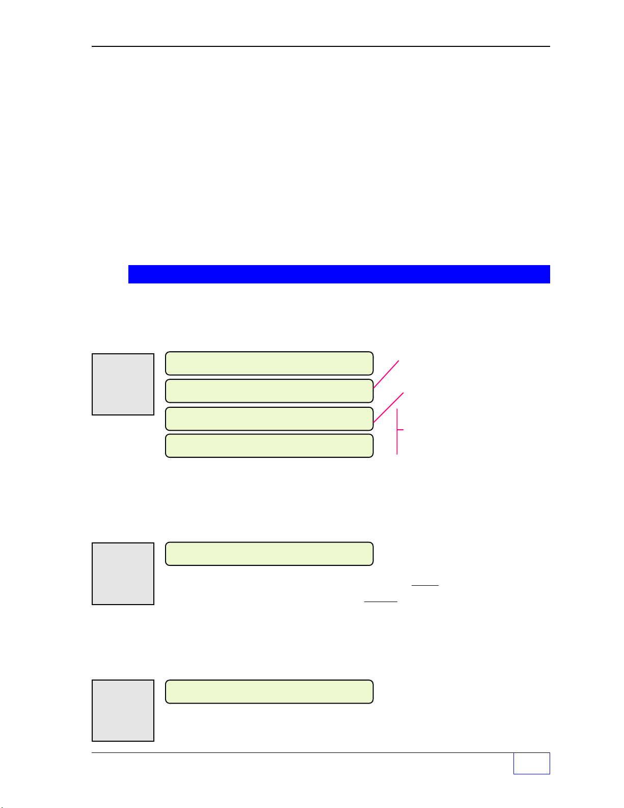
Product Overview
The INCON TS-1001 / 2001 /504 / 508 / 750 Tank Sentinel® consoles are complete leak detection
and inventory monitoring systems. The TS-750 / 1001 / 2001 models run in-tank leak tests
with exceptionally high accuracy. The TS-504 / 508 models are designed for monitoring and
controlling liquid levels in aboveground storage tanks.
The tests meet or exceed all current EPA standards.
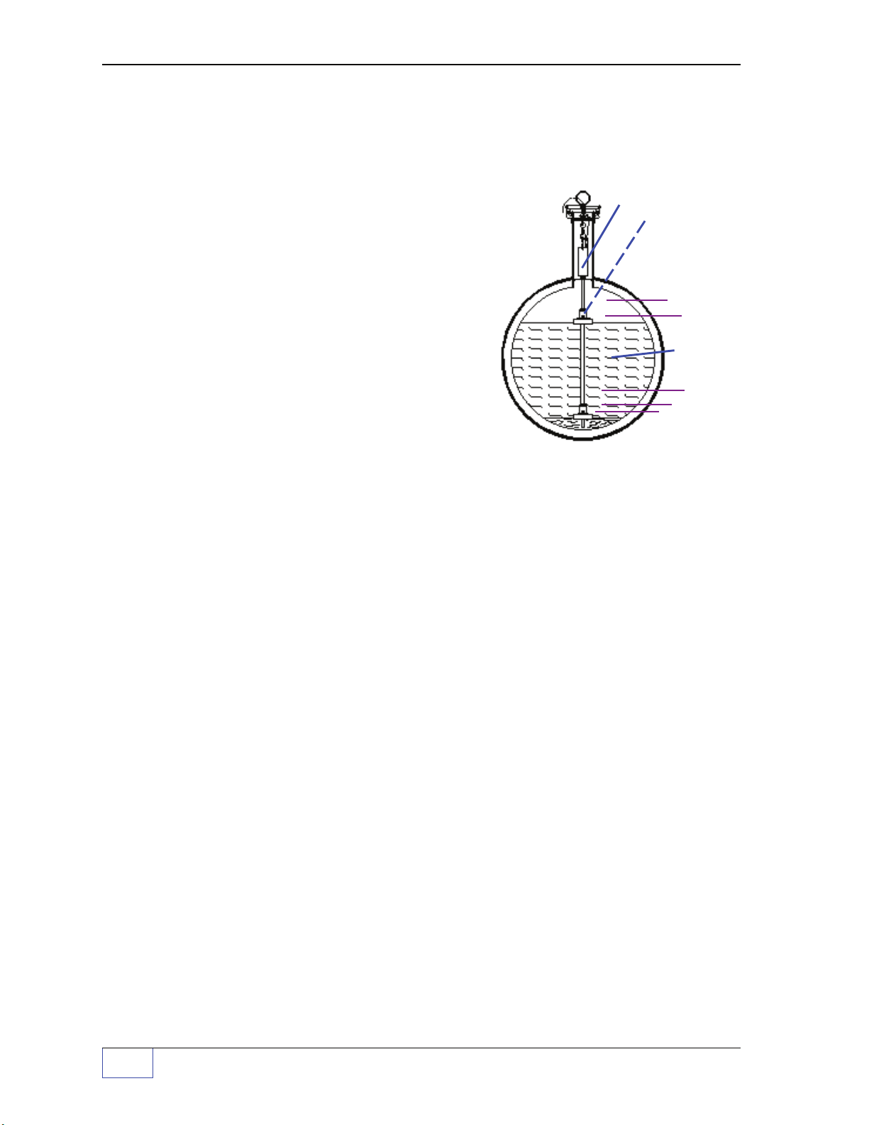
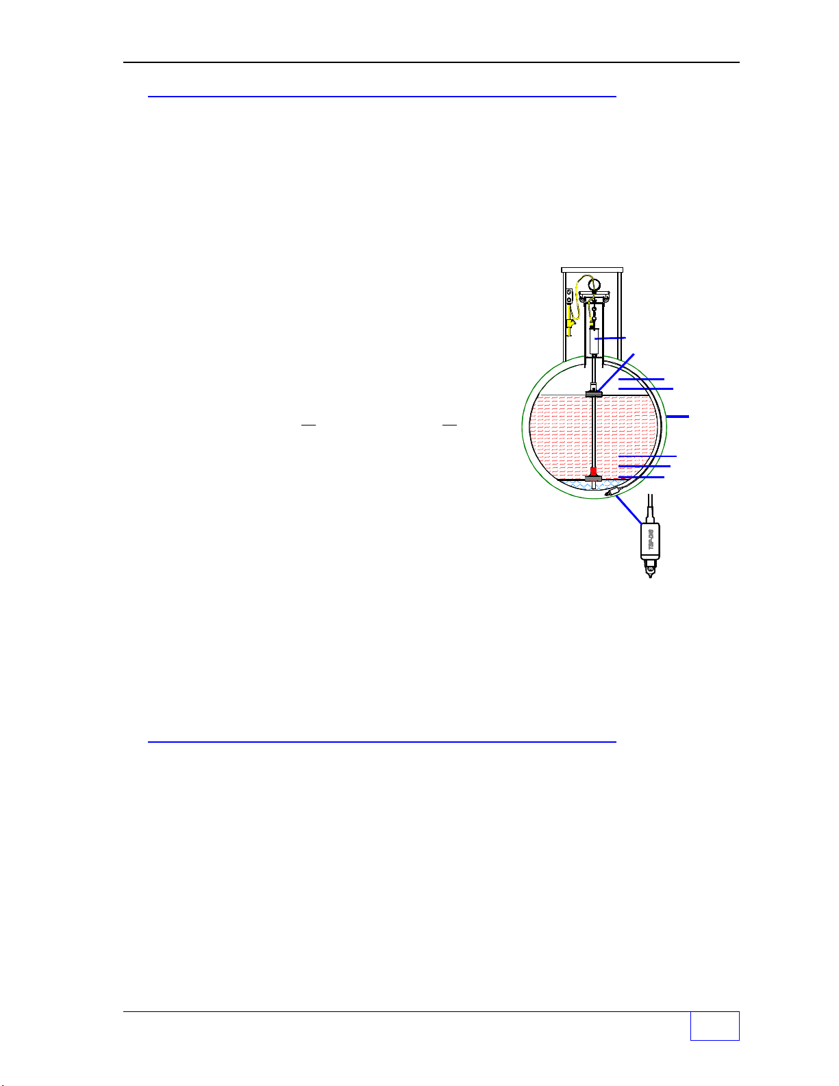
Liquid Level Probe &
Floats
A broad range of liquid products can be leaktested and inventory-monitored (or gauged)
simultaneously in many storage tanks.
PROGRAMMED
TANK RELATED
ALARM LIMITS
HIGH HIGH
HIGH
:
Inventory monitoring is done with a very
special sensor called a
Liquid Level Probe
Product
that has a product float. With petroleum
products, water floats are used. When a
programmed limit is reached, then a tank-
LOW
LOW LOW
HIGH WATER
related alarm will be produced at the console
for that specific tank.
Additionally, these consoles can monitor a wide variety of leak detection sensors which
are installed within – the walls of double-walled tanks (DW or DWTs), containment sumps,
dispenser pans, and groundwater or vapor monitoring wells near USTs. Leak detection
sensors produce alarms when exposed to liquids such as product. Some produce alarms
at various liquid levels, or when water is absent (as with a ground water monitoring well
sensors), or when they are exposed to hydrocarbon vapors (as with a vapor sensor).
Of the many types of leak detection sensors that are available from INCON, these can be
divided into two basic types — one is called a Standard Sensor and the other is called a
BriteSensor™.
BriteSensors™ are sensors with built-in intelligence. Within them is a small computer that
uses digital data to communicate with the system console. The data sent identifies the
sensor-type and status of each alarm that it can detect. Some BriteSensors can tell the
difference (discriminate) between water and a hydrocarbon (product) and will produce
different alarm-codes for each of these.
On the other hand, Standard Sensors do not use digital data. Instead, the Standard Sensor
operates like an ON–OFF switch that’s
closed when no liquid is present
a liquid is detected. When a liquid is detected, the loss of signal produces a standard
sensor alarm at the console.
P Page P - ii Tank Sentinel Operator’s Guide
– or – open when
Page 9
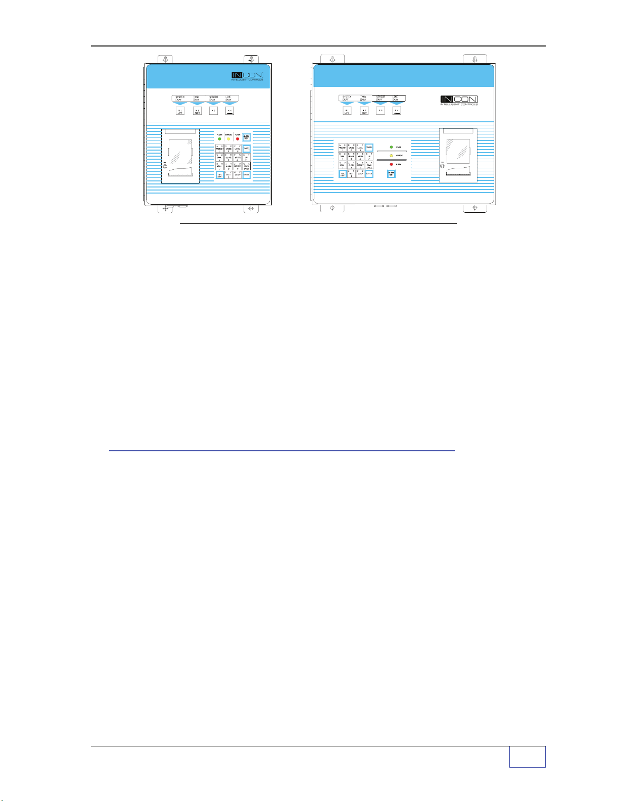
TS-1001 TANK SENTINEL
Figure P - 1 TS-1001 & TS-2001 Model ATG Consoles
®
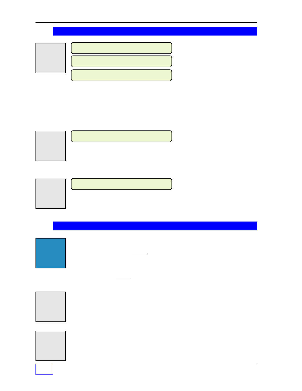
Alarms and Warnings –
Alarms and warnings are designed to alert you / make you aware of a problem when it
occurs so you can take appropriate corrective action. System hardware fail warnings, tank
related alarms, leak detection sensor alarms, and line leak alarms can be customprogrammed to do many things. These events that require
a (p) below:
– cause the red Alarm light or yellow Warning light to flash (standard)
– activate / sound the console annunciator alarm horn (p)
– activate output relay(s) /
– print alarm reports automatically at the report printer (
– send reports to remote location(s) –
optional
TS-2001 TANK SENTINEL
®
programming
external alarm device (p)
)
p
optional
TS-FM2 fax/data modem req’d (p)
are denoted by
Tank Sentinel® Features
•
The Models TS-1001, 504 & 750 can monitor product in up to 4 tanks
•
The Models TS-2001 & 508 can monitor product in up to 8 tanks
•
The TS-1001 can monitor up to 12 leak detection sensors internally
•
The TS-2001 can monitor up to 24 leak detection sensors internally
•
The TS-504 , 508 & 750 can monitor up to 8 leak detection sensors internally
•
External sensor expansion capability — all consoles can be expanded with 1 or 2
external TS-SEM sensor expansion modules — for an additional 8 or 16 sensors inputs
•
All consoles use advanced technology and can be custom programmed to operate per
your specific needs and management style
•
All models can be programmed to create logical groups of sensors or tank limits
(i.e. by tank, by monitoring well fields, by product type, or by product limits)
•
TS-1001/2001 consoles can be programmed for automatic operation and generation
of reports, and to comply with your local EPA regulatory requirements – for leak testing
and leak detection
•
All consoles can be equipped with an
alarms, reports, and test data can be sent to remote locations
optional
TS-FM2 internal fax-modem — deliveries,
PREFACE Page P - iii P
Page 10

Tank Sentinel® Features (
•
All consoles can communicate with remote computers for off-site notification, management,
and dispatch requests with the
•
Access to the Tank Sentinel console door is key-locked for security, and the database /
setup-configuration program mode can be protected by security passwords to protect
the operation and function of the tank gauge.
•
The Tank Sentinel systems can be equipped with many optional accessories or
programs such as: Tank Overfill Alarm and Acknowledge units, SCALD (Statistical and
Continuous Automatic
•
TS-1001/2001 consoles can be upgraded with a unique input code after receipt of a
purchase order and the console serial number. For instance, a 2 tank TS-1001 can be
upgraded to 4 tanks, or SCALD upgrade added either locally on-site, or remotely (remote
upgrade is possible with the
•
All consoles can monitor product lines for leaks when the INCON
Detector) Interface is used. Many line reports can be produced from the collected data,
such as the versatile Regulatory Report.
•
All models can be programmed to use either:
– SI Units ( litres = liters / l / L, centimeters / cm / CM, Celsius /°C/C )
English System of Units ( gallons / GAL / G, inches / IN, Fahrenheit / °F / F )
Throughout this manual, the volume length and temperature values are shown in US
Units.
CONTINUED
optional
tank
Leak Detection
optional
... )
data or fax modem.
testing
).
data / fax-modem).
1)
Metric International System of Units
TS-LLDI
or 2)
(Line Leak
US
.
Safety
Intrinsically safe circuits for liquid level probes, and leak detection sensors mounted in:
Class I, Division 1, Group D hazardous locations.
Approvals
All Tank Sentinel models are UL and cUL Listed 6L79 as Liquid Level Gauge / Leak
Detection Systems. Third party approved leak detection — Pd (probability of detection) =
99.2 % for 0.1 or 0.2 gph leak tests (0.1 = precision test, 0.2 is the monthly regulatory
compliance test)
Need Help ? – Names and Phone Numbers to Contact
See the inside front cover of this manual. When you first read this manual, please take
time to fill-in the Contact Names, Phone Numbers and when to contact these people or
organizations (i.e.: local / State EPA Regulatory Agency).
NOTE
☞
...Reference the Table of Contents for specific topics, and the Glossary for technical
definitions and explanations.
and all corrective actions to take should a problem, alarm, or warning occur.
Also be familiar with the Policy and Procedures at your site
—
P Page P - iv Tank Sentinel Operator’s Guide
❖
—
Page 11

1 Console – Basic Operation
Contents:
Operating Modes,
Component Location
Display (Run Mode, Normal
Warning and Alarm
Indications, Sentinel Mode,
Tank or Line Testing)
Menu Keys (M1 – M4),
Status Row & Alarm Test key,
Keypad Keys,
Optional Report Printer,
General
Once the Tank Sentinel console has been
interaction with the system is through the keypad, display and printer. All of the basic
features of the system are available through these input / output devices.
Operating Modes
There are three operating modes of the Tank Sentinel console, these are:
the RUN mode, the SENTINEL mode, and the SETUP programming mode.
Paper Advance-Button,
RS232 CommunicationPorts,
TS-FM1/TS-DOM Receptacle,
Model & Serial No. Label,
Product & Tank-Related
Keys:
PRODUCT, GROSS, LEVEL,
TANK, ULLAGE, WATER
Menu-Related Keys:
CANCEL, UP, DOWN,
ENTER, MENU
installed, programmed, and tested
Special Keys:
ALARM, REPORT... Selecting
a Report, Report Features
CHECK Date & Time,
Display, Printer, Dialtone,
Software & Hardware
Options
TEST, Starting tests, test
Status, Aborting tests
ACK-SHIFT Key & Uses
Upgrade Menu
most of your
1) The RUN mode is the normal operating mode when product dispensing is expected (the
site is open for business). Inventory levels and deliveries are monitored and all leak
detection sensors are active during this time.
2) The SENTINEL mode is the after-hours watch mode when dispensing is not expected,
and the site is not open for business. Deliveries and unauthorized dispensing (thefts)
are monitored, and coarse leak tests or compliance leak tests run during this time (after
normal business hours). The start and stop time of the sentinel mode must be
scheduled in the setup programming mode.
3) The SETUP programming mode is where automatic operation, configuration, alarmlimits, and the overall system operation is defined and set. This mode can be
password protected — this is highly recommended to protect the system-operation
from unintentional changes or acts of vandalism. Inventory levels, delivery detection,
and all leak detection sensors are not active during this mode.
WARNING
it is possible to alter the system and make it nonfunctional, unable to detect
leaks, or be out of compliance with EPA rules and regulations.
INCON does not recommend changing the system-setup because
NOTE
☞
Let your authorized INCON service-provider do the setup programming – look at the inside of the
front cover for contact name(s) and phone number(s).
Console – Basic Operation Page 1 - 1
1
Page 12
®
SYSTEM TANK SENSOR LINE
OKAY OKAY OKAY OKAY
Tank Sentinel
AUTOMATIC
ODEL
120
:
TS-1001
121795
VAC, 50 / 60 Hz
A
MPS MAX
:1
TANK GAUGE
&
LEAK
DETECTION
SYSTEM
MADE IN
USA
M
S/N:
INTELLIGENT CONTROLS, INC. SACO, ME 04072 USA
®
PN 240-1187
TS -1001
TANK SENTINEL
Door hinge
(left side)
Figure 1 - 1. Console Component Identification – TS-1001 shown typical
Console Component Location – see Figure 1-1 above
➀
Display
The light-green backlit display consists of two rows that are 40 characters long.
Run Mode Display
The Tank Sentinel console shows up to four status-display columns in the normal run
mode. The heading names of these are: System, Tank, Sensor, and Line.
Display Normal Indications
OKAY is shown under each status-display column.
Display WARNING Indications ( also see Status Row ➂ )
WARNING is shown under the SYSTEM display column when a system software or
hardware failure occurs ( i.e. FAX HARDWARE FAILURE )
Display ALARM Indications ( also see Status Row ➂ )
M1 M2 M3 M4
LEFT RIGHT
See Tank and Line
Display Notes
a & b (next page)
ALARM is shown under a
occur ( i.e.
1
Page 1 - 2 Tank Sentinel Operator’s Guide
TANK
HIGH LIMIT
, HIGH BRINE, 0.2 GPH LINE LEAK )
, SENSOR, or LINE display column(s) when alarms
Page 13
Sentinel Mode Display
SYSTEM TANK SENSOR LINE
OKAY SENTINEL OKAY TESTING
SYSTEM TANK SENSOR LINE
WARNING TESTING ALARM OKAY
Under the word TANK, SENTINEL is alternately displayed with OKAY or ALARM when the
Sentinel mode is running. Sentinel-mode is programmed to run after business hours and
will monitor for product thefts and gross tank leaks.
M1 M2 M3 M4
LEFT RIGHT
Tank or Line Testing Display
Under the word TANK or LINE, TESTING is alternately displayed with OKAY or ALARM
when leak test(s) are running. Tests can either be started manually, or scheduled (setup)
to run at certain times of the month, week, or day. A tank leak test estimate report can be
printed by using the
REPORT
be (aborted), by using the
See Tank and Line
Display Notes
a & b (below)
key. A leak test status can be displayed, and a leak test can
TEST
key.
See Tank and Line
Display Notes
a & b (below)
M1 M2 M3 M4
LEFT RIGHT
Tank & Line Display Notes:
a.) The tank-status display and any tank-related menus or reports do not appear unless
the number of tanks are setup / programmed for 1 or more tanks. A Leak Detection
System (tanks set to Ø) can monitor leak detection sensors, but does not monitor intank product levels.
b.) The line-status display, and any line-related menus or reports will not appear unless
INCON Line Leak Detectors are connected to the TS-LLDI interface terminals, and the
number of lines are setup (programmed) for 1 or more lines.
➁
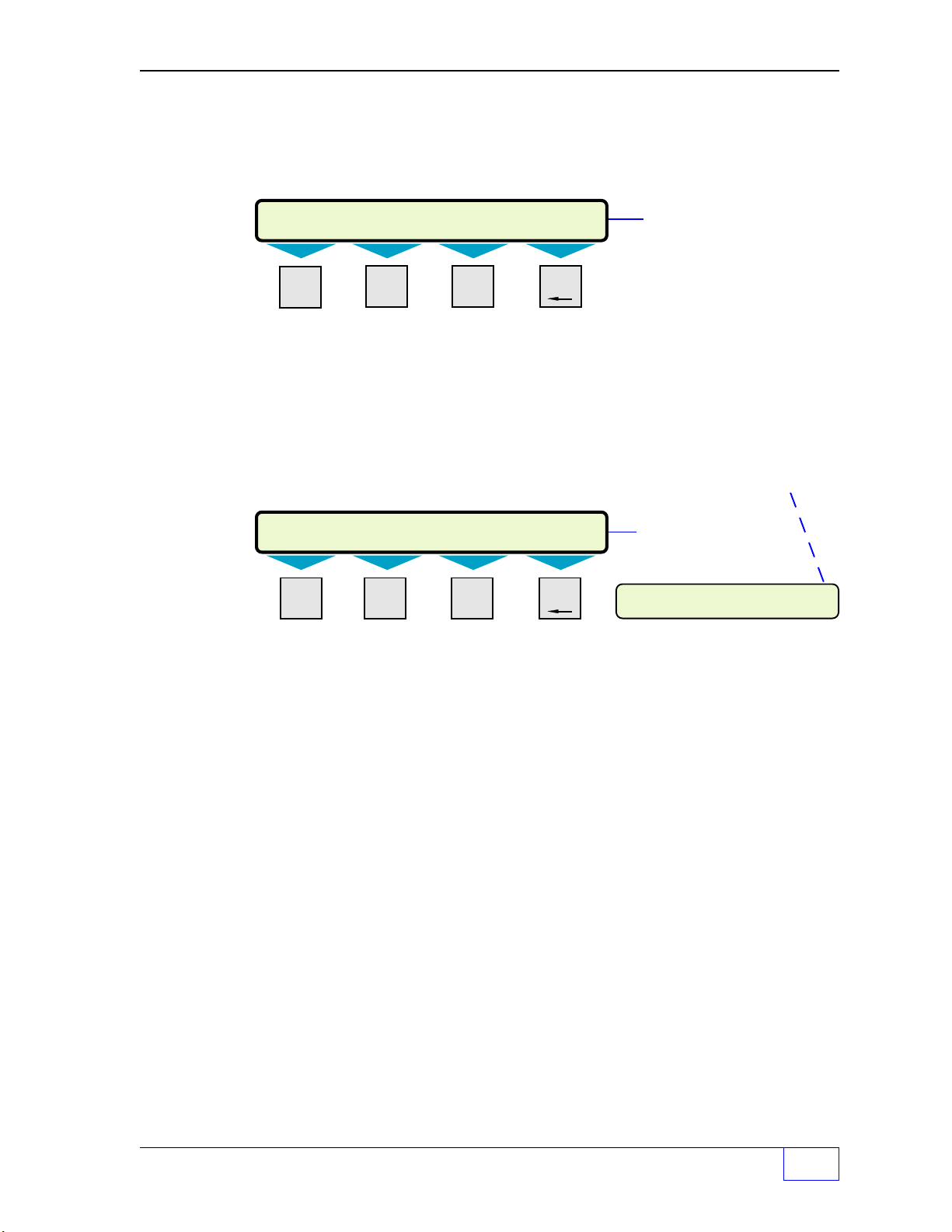
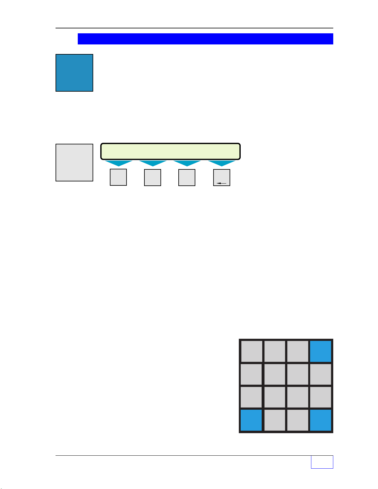
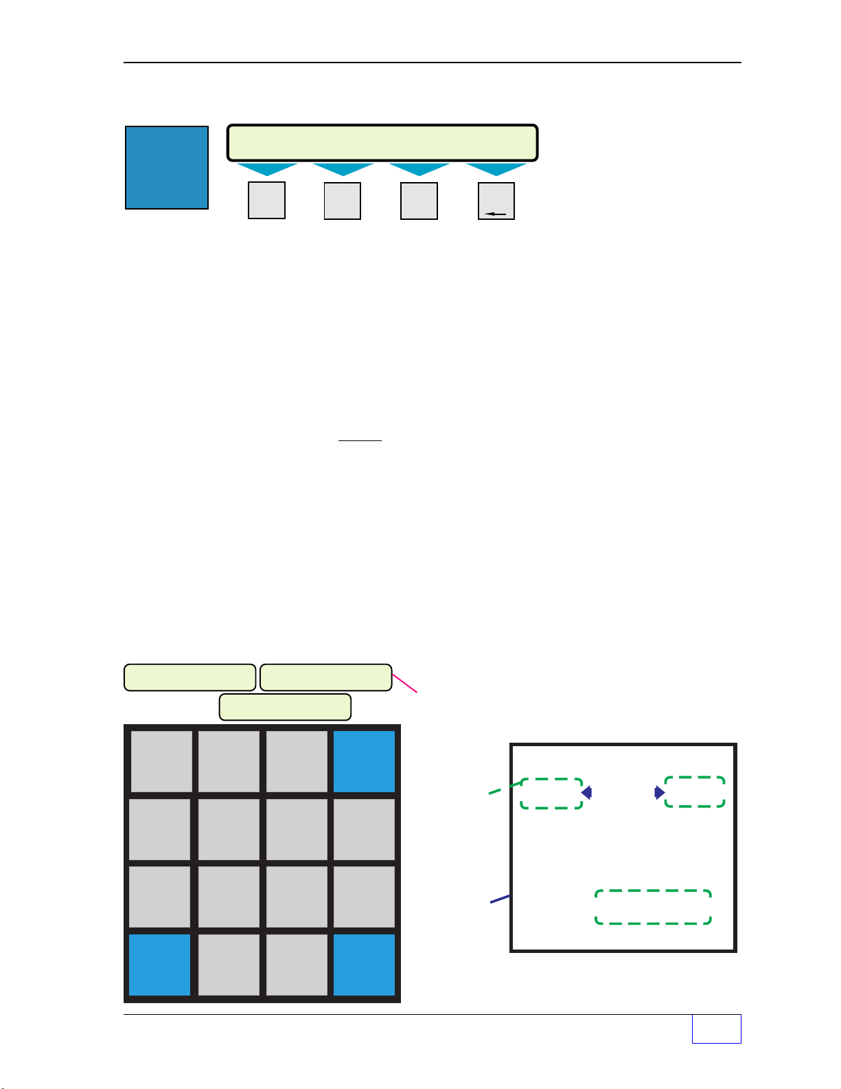
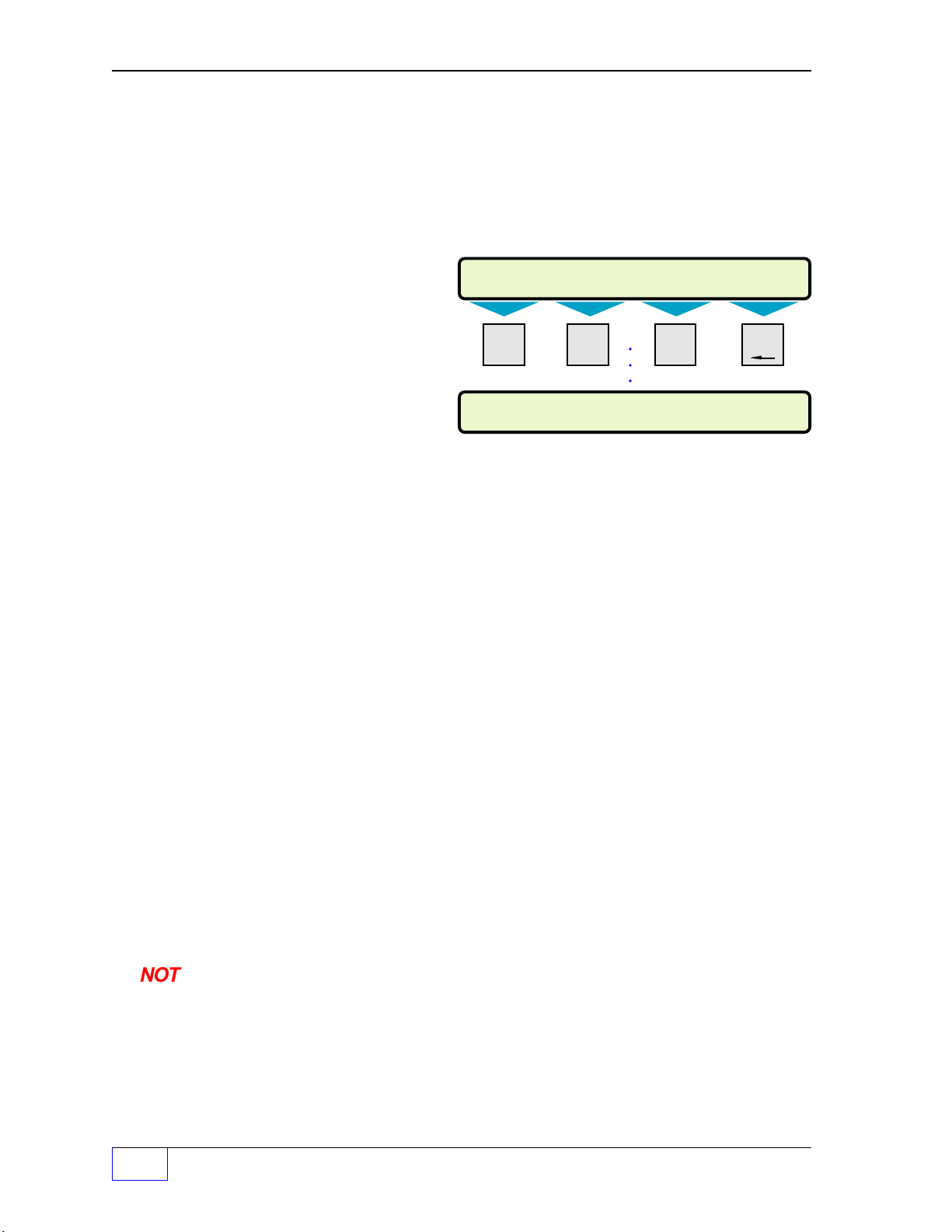
Menu keys (M1 thru M4)
Menu keys
are used to: make menu selections (see the
information (see above... press a
control the cursor, or delete a character when a number or letter input is required from the
keypad
left and
{
M4
M2
moves the cursor right }.
SELECT LEAK TEST OPTION
STATUS START ABORT
...see graphic above
ALARM
Menu key
to display current alarms). Menu keys can
can backspace / delete a input character ( xxx_ï),
key) and to display
M1
moves the cursor
Console – Basic Operation Page 1 - 3
1
Page 14
Component Location ( Continued... see Page 1 - 2 Figure 1 - 1 )
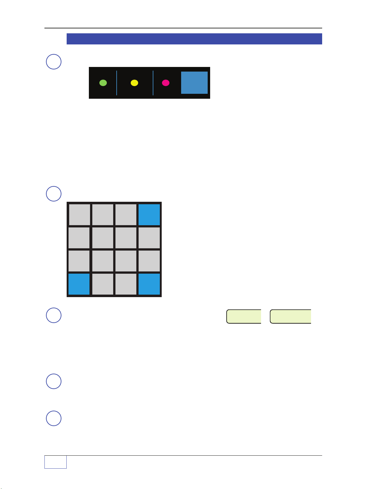
Status Row
3
NOTE
Keypad Keys
4
A N
PRODUCT
1
D Q
TANK
4
H U
MENU
7
ACK
SHIFT
(with Alarm Test Key)
POWER
WARNING ALARM
ALARM
TEST
TS-1001/ 750 / 504 Status Row shown
( TS-2001/508 is vertical )
GreenPOWER on Light: On steady when the console power is on
Yellow WARNING Light: Flashes for System fail warnings
RedALARMLight: Flashes for Tank, Sensor, or Line alarms
ALARM TEST Key: Press to test the annunciator alarm horn
After a warning or alarm is acknowledged, the flashing yellow-warning light or
red-alarm light will stop flashing and will stay on continuously (solid) until the condition
clears or no longer exists, which will cause it to turnoff (see Chapter 2).
B O
GROSS
2
E R
ULLAGE
5
I V
ALARM
8
L Y
TEST
0
C P
LEVEL
3
F S
WATER
6
J W
REPORT
9
M Z
CHECK
.
CANCEL
G T
UP
+ / –
K X
DO WN
SPACE
ENTE R
The Keypad Keys and Menu keys are used to:
Display product and tank data, access the setup program,
view alarms, select reports (to print or Fax), navigate
through menus and make choices, silence alarms,
acknowledge alarms, start or stop (abort) leak tests, and
to check the system time, display, printer operation, and
to check options (such as the tank gauge part and
version number, and the operational status of all
connected hardware).
Report Printer
5
The printer requires a special roll of thermal printer paper to produce scheduled reports,
automatic alarm reports, and reports selected from the keypad. Reports cannot print
without paper. See Chapter 5 Routine Maintenance about replacing the roll of paper when
the Paper Out warning is flashed (above).
Paper Advance Button
6
Press to advance the printer paper (use when replacing the paper roll).
RS232 Communication Ports
7
Two RS232 ports are supplied for remote communications and interfacing with other
equipment (card readers, POS terminals... also see # ).
1
Page 1 - 4 Tank Sentinel Operator’s Guide
SYSTEM......
WARNING
SYSTEM
PAPER OUT
Page 15
➇
SELECT PRODUCT
REGULAR XTRA PLUS
REGULAR GROSS NET WTR VOL ULLAGE
MAN 1 5960 6860 93.3 4087
GROSS TANK 1 TANK 2 TANK 3 TANK 4
GALLONS 22080 12080 8080 2480
LEVEL TANK 1 TANK 2 TANK 3 TANK 4
INCHES 98.25 86.10 64.53 24.71
REGULAR GROSS NET WTR VOL ULLAGE
TANK 1 3813 3770 33.3 1510
REGULAR GROSS NET WTR VOL ULLAGE
TANK 2 3147 3090 60.0 2577
TS-FM2 Receptacle
Remote communications (telephone) port for the
Modem (TS-FM2). After a fax/modem is installed and the communications program is
setup, modem data can be sent to up to 4 different numbers in response to deliveries,
alarms, or leak test results. With the
can also be faxed on a automatic schedule, or manually on-demand using the keypad, to
1 to 4 different fax machine numbers (programmed in the FAX – REPORTS setup menu).
➈
Model & Serial Number Label
This label also specifies the Voltage, Hertz, and Amperage rating of the console.
Product & Tank Related Keys (ALSO SEE THE GLOSSARY)
Depending on which units have been selected, level units are in inches (or centimeters),
volume units in gallons (or liters), and temperature units in Fahrenheit (or Celsius).
AN
PRODUCT
1
optional
optional and enabled
internal Data Only Modem or Fax
TS-FM2 Fax Modem, reports
Manifold tanks display the
TOTAL
...press DOWN to display
individual tank data when tanks
are manifold
...The last two displays are
typical for non-manifold tanks
values initially
PRODUCT
the WTR VOL (water volume), and ULLAGE of all tanks containing that product (press
DOWN to display by tank or manifold). REGULAR shown above.
BO
GROSS
2
GROSS
NET, the GROSS product volume is not temperature compensated.
Gross volume changes as the product temperature changes
contraction or expansion). After a delivery, the fluctuations in gross volume will subside
as temperature stabilizes
CP
LEVEL
LEVEL
3
same as an electronic dipstick reading. Also see TANK.
shows the PRODUCT name, the total GROSS volume, the total NET volume,
Press DOWN for other tanks.
shows the physical product volume in each tank minus any water volume. Unlike
(because of thermal
(see Chpt 4 about Tank Leak Test Requirements).
Press DOWN for other tanks.
shows the actual physical height of the liquid in each tank. The level display is the
Console – Basic Operation Page 1 - 5
1
Page 16
Product & Tank Related Keys ( CONTINUED... )
WATER TANK 1 TANK 2 TANK 3 TANK 4
INCHES 1.8 1.6 1.5 1.0
ULLAGE TANK 1 TANK 2 TANK 3 TANK 4
GALLONS 2020 1020 383 220
SELECT TANK
TANK 1 TANK 2 TANK 3 TANK 4
REGULAR GROSS NET WTR VOL ULLAGE
TANK 1 22080 21855 93.3 2020
REGULAR LEVEL TEMP WTR LVL PERCENT
TANK 1 98.25 67.8F 1.8 93.5
DQ
T ANK
4
TANK
(which is temperature-compensated), WTR VOL (water volume), ULLAGE (gross volume
that could be added to fill the tank), actual product LEVEL, product TEMP (temperature),
WTR LVL (water level), and PERCENT full (capacity) values of the selected tank.
ER
ULLAGE
5
FS
Ullage shows the
(to 95 % full / capacity).
Press DOWN for other tanks &
Press a menu key to select a tank
Press DOWN to see additional tank
data
...(product level, temperature,
water level, and percent full)
shows the PRODUCT name, the GROSS product-volume, NET product-volume
Press DOWN for other tanks.
gross volume
that could be added to fill a tank without overfilling it
Press DOWN for other tanks.
W ATER
6
Displays the actual
WTR VOL (water volume) and WTR LVL (water level).
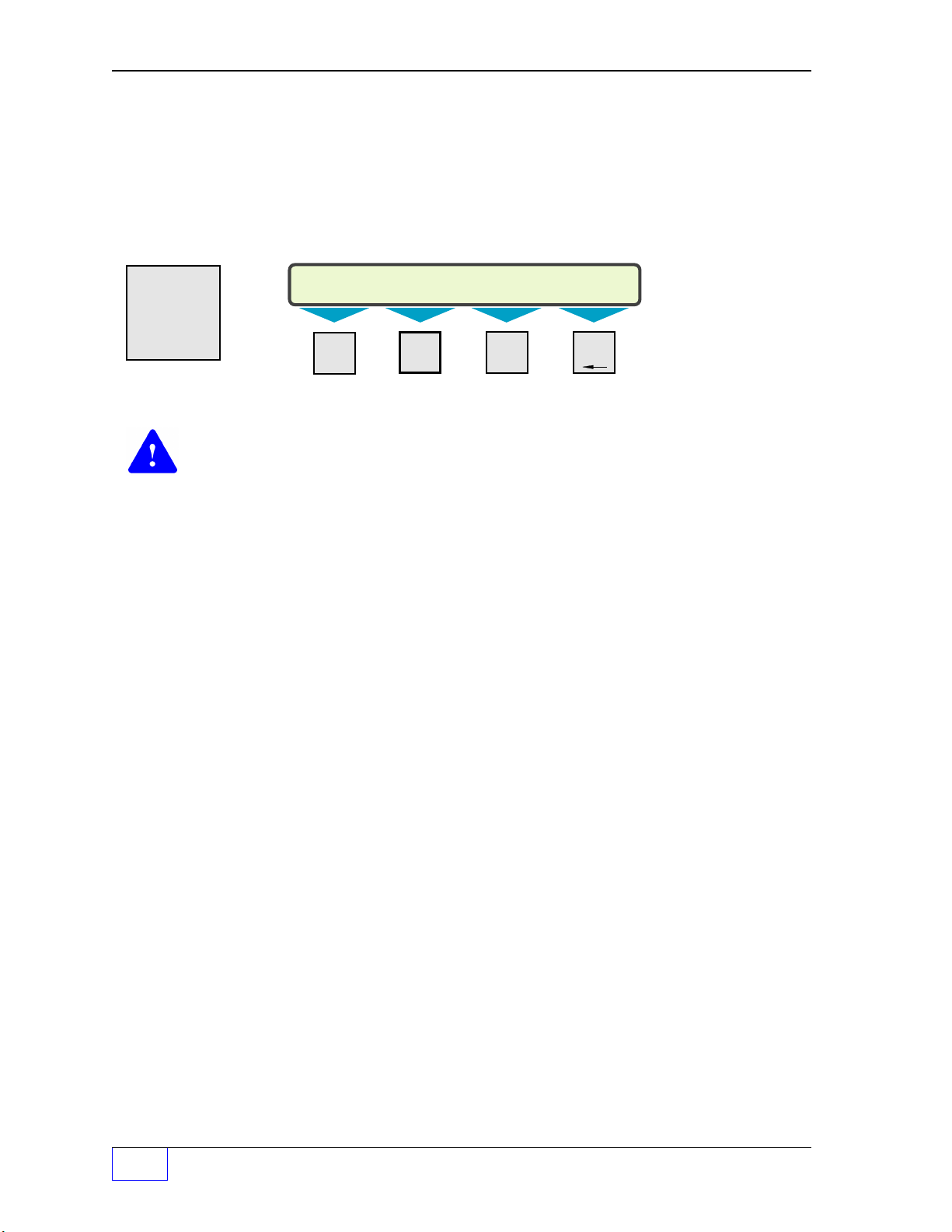
Menu Related Keys
The
CANCEL
•
•
•
•
GT
UP
+
/ –
KX
The
UP
The
Press
DOWN
be pressed repeatedly (it will not scroll through a menu if it’s held-down).
SP A CE
water level
CANCEL
key (upper right key) has many uses. Press
cancel a menu choice (before the
in each tank. Press the TANK key to display both
ENTER
CANCEL
key is pressed)
to:
return to default status display
exit out of and to return to a previous upper level menu or parent menu
cancel an input (before the
UP
key is used to travel up through a menu.
ENTER
key is pressed)
must be pressed repeatedly (it will not scroll through a menu if it’s held-down).
DOWN
key is used to travel down through a menu.
DOWN
when a menu is first accessed or entered. The
DOWN
key must also
1
Page 1 - 6 Tank Sentinel Operator’s Guide
Page 17
Menu Related Keys ( CONTINUED... )
SELECT MENU OPTION
SETUP UPGRADE LANGUAGE DATALOG
The
ENTER
•
•
•
HU
MENU
ENTER
key has many uses. Press
ENTER
to:
accept a setup menu choice or input value for storage into memory
accept or to change the number of reports to print (to save paper)
accept an alphanumeric code input... Examples uses are:
1) accept an alarm acknowledge password
2) accept an upgrade password and string sequence to upgrade the system
(when adding equipment or enhancing the system operation)
7
M1 M2 M3 M4
LEFT RIGHT
The
MENU
•
access the SETUP program mode
•
access the UPGRADE menu (to expand the system or add/enable optional
key is used to:
(access should be password protected)
, or
features). Upgrades are optional extra cost features that expand the number of tanks
monitored, add the FAX/Modem, or add software capabilities. Please contact your
Authorized INCON tank gauge distributor for pricing and availability. See the warning
below.
•
access the LANGUAGE menu (to change the display and report language)
•
to datalog (this is a technical diagnostic menu only)
AN
PRODUCT
1
BO
GROSS
CP
LEVEL
2
CANCEL
3
DQ
TANK
HU
MENU
ACK
SHIFT
4
7
ER
ULLAGE
5
IV
ALARM
8
LY
TEST
0
Console – Basic Operation Page 1 - 7
FS
WATER
6
JW
REPORT
9
MZ
CHECK
.
GT
UP
+/–
KX
DOWN
SPACE
ENTER
1
Page 18
Menu Related Keys ( CONTINUED... )
SELECIONE
LINGUAGEM
INGLES FRANCES ESPANHOL
PORTUGUES
SELECCIONAR
IDIOMA
INGLES FRANCES
ESPANOL
PORTUGUES
SELECTIONNER
LANGUE
ANGLAIS
FRANCAIS
ESPAGNOL PORTUGAIS
SELECT
LANGUAGE
ENGLISH
FRENCH SPANISH PORTUGUESE
SELECT MENU OPTION
SETUP UPGRADE
LANGUAGE
DATALOG
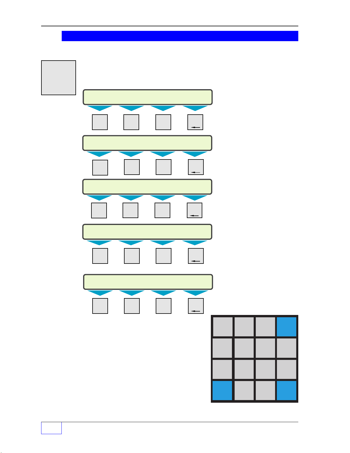
Changing the Display and Report Language
HU
MENU
use (English is the
directly under the desired language ...changes are immediate.
7
Press the
MENU
key and then the M3 menu key. Choose the language that you want to
default
M1 M2 M3 M4
LEFT RIGHT
language), and then press the menu key (
M1 M2 M3 M4
LEFT RIGHT
M1 M2 M3 M4
LEFT RIGHT
M1 M2 M3
English
default
selected
French selected
or M4)
M1 M2 M3 M4
LEFT RIGHT
M1 M2 M3 M4
LEFT RIGHT
Spanish selected
Portuguese selected
AN
PRODUCT
1
DQ
TANK
4
HU
MENU
7
ACK
SHIFT
BO
GROSS
ER
ULLAGE
IV
ALARM
LY
TEST
2
5
8
0
CP
LEVEL
3
FS
WATER
6
JW
REPORT
9
MZ
CHECK
.
CANCEL
GT
UP
+/–
KX
DOWN
SPACE
ENTER
1
Page 1 - 8 Tank Sentinel Operator’s Guide
Page 19
Special Keys ( ALSO SEE THE GLOSSARY )
REGULATORY REPORT
PRINTER FAX
SELECT REPORT GROUP (MORE)
SENSOR ALARM SETUP REGULATORY
SELECT REPORT GROUP (MORE)
INVENTORY DELIVERY USAGE TEST
SELECT SENSOR ALARM STATUS
ACTIVE CLEARED HISTORY
SELECT ALARM TYPE (MORE)
ALL
SELECT ALARM TYPE (MORE)
SYSTEM TANK SENSOR LINE
IV
ALARM
8
NOTE
☞
The annunciator may be programed to pulse (modulated) or to output a continuous
(solid) tone for certain alarms.
could be sent to remote locations IF the console is properly programmed and has
an
M1 M2 M3 M4
LEFT RIGHT
M1 M2 M3 M4
LEFT RIGHT
M1 M2 M3 M4
LEFT RIGHT
In addition, alarms, deliveries, and leak test results
optional
internal TS-FM2 Data or Fax Modem ➇.
Pressing the
ALARM
key will
display the types of alarms:
SYSTEM TANK SENSOR LINE
and ALL alarms (ALL is shown if
the
DOWN
key is pressed).
Press a menu key under one of
these types to display a status
group to choose from (Active,
Cleared, or History).
Also see the
ACK
SHIFT
key
about how to acknowledge
alarms.
JW
REPORT
9
(MORE) =
press the
DOWN
key to
display more
choices
Selecting A Report
Press the
a report that you want to print or fax. For example, to print a SENSOR ALARM HISTORY
report, press the following keys:
(under SENSOR), and finally
M1 M2 M3 M4
LEFT RIGHT
M1 M2 M3 M4
LEFT RIGHT
M1 M2 M3 M4
LEFT RIGHT
REPORT
key to display the report groups: Press the appropriate menu key under
REPORT DOWN
M3
(under HISTORY).
The report key can send reports
to either the
optional
console
printer ➄, or to fax machines if
the console is equipped with the
optional
➇ TS-FM2 Fax Modem.
The number of available reports
is extensive and the choices are
presented in a multilevel fashion.
See Chapter 3 Tank Sentinel
Reports for example reports
and descriptions.
M2
(under the ALARM text)
M3
Console – Basic Operation Page 1 - 9
1
Page 20
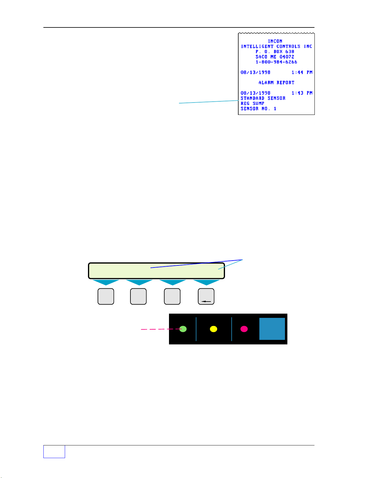
Report Features
SELECT FUNCTION 07:16:47 PM 12-23-1997
DISPLAY PRINTER DIALTONE OPTIONS
See Chapter 3 ...Reports may be programmed or scheduled to print automatically at certain
times (for example, during work shifts, every day, every week on a particular day, or every
month on a particular day). Other reports can be automatically fax’d or printed when an
alarm occurs, or when a non-alarm event happens (for example, when the result of a Leak
Test is available).
MZ
CHECK
.
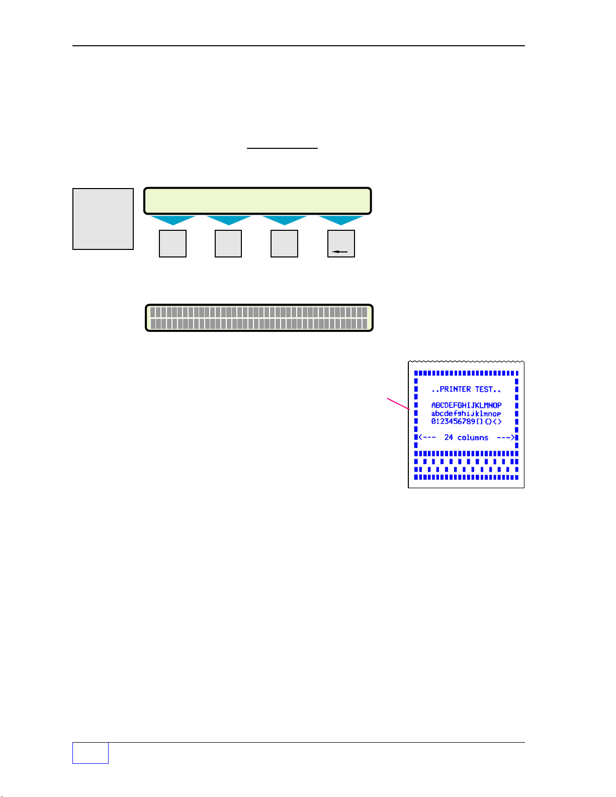
Check Display, Printer, or Dialtone
Press the
—
Press the
to check the Printer / printout a test report. The report
should be uniformly dark, clear, & legible.
Press the
DIALTONE to check for a Dialtone. Either a
NO DIALTONE DETECTED message is shown, or a
DIALTONE DETECTED message appears when both the
internal Fax / Modem hardware and the phone line are
installed and working correctly.
M1 M2 M3 M4
LEFT RIGHT
CHECK
PPP P P P P P P P P P P P P P P P P P P P P P P P P P P P P P P P P P P P P P P
P P P P P P P P P P P P P P P P P P P P P P P P P P P P P P P P P P P P P P P
press the
CHECK
key and then
CANCEL
key and then
CHECK
M1
to check the Display (shown below). NOTE:
key to show / go back to the
Menu
key under PRINTER
key and then
Menu
key under
CHECK Date &Time
Press the
CHECK
key to show
the time and date.
NOTE: DIAL T ONE appears
when an internal TS-FM2
Fax / Data Modem is installed.
the 40 segments of each row
should show a reversed P
CHECK
menu (above).
Check Software & Hardware Options
Press the
CHECK
go through the list (below):
(Software Options) ______________________ Part Number
(Software Options) ______________________ Version Number
(Hardware Option): PROBES, TS-CIM, TS-ROM, TS-SEM 1, TS-SEM 2, and
(Hardware Option) TS-IEM — TS-2001/508 consoles only, and
(Hardware Option): LINES, PRINTER, and FAX MODEM
NOTE
Each hardware option / status-check will display one of the four following
messages: OPERATIONAL, NOT INSTALLED, OUT OF PAPER, or TROUBLE
☞
1
(also see Chapter 5 ).
Page 1 - 10 Tank Sentinel Operator’s Guide
key,
Menu
key under OPTIONS, and then press the
DOWN
key to
Page 21
Special Keys ( Continued... )
SELECT LEAK TEST OPTION
STATUS START ABORT
SELECT LEAK TEST TO START
0.1 TANK 0.2 TANK
SELECT TANK TO START 0.2 TEST (MORE)
TANK 1 TANK 2 TANK 3 TANK 4
SELECT TANK TO START 0.2 TEST (MORE)
ALL TANKS (or ALL LINES for Line Leak Tests)
ACTIVE LEAK TESTS (UP/ DN)
TANK 1 0.2 GPH STARTED 08:53:54PM
ACTIVE LEAK TESTS (UP/ DN)
TANK 3 0.2 GPH STARTED 09:12:04PM
NO ACTIVE LEAK TESTS (are running)
LY
TEST
0
M1 M2 M3 M4
LEFT RIGHT
The
TEST
key is used to: check
the Status of running tank or line
leak tests, or to Start or Abort a
test.
NOTE
Because
SCALD® is a
S tatistical
C ontinuous
A utomatic
L eak
D etection
program
that runs
Tank-LeakTests
continuously,
SCALD leak
tests are
not
included
with
standard
Active Leak
Tests.
1) Press the
2) Choose the type of test below (press a
LEFT RIGHT
3) Choose the Tank or Line # (press a
LEFT RIGHT
4) Choose ALL – press
LEFT RIGHT
Press the
or
DOWN
TEST
key and then the
M2
key (above)
menu key
M1 M2 M3 M4
menu key
M1 M2 M3 M4
DOWN
M1 M2 M3 M4
TEST
key, the
M1
and then the
key, and then the
key to show the Status of other Leak
M1
Tests.
M1 M2 M3 M4
LEFT RIGHT
M1 M2 M3 M4
LEFT RIGHT
– or –
M1 M2 M3 M4
LEFT RIGHT
UP
Starting a tank or Line
)
Leak Test:
Follow the steps to the left &
follow test requirements in
Chapter 4.
)
Once a Tank or Line is chosen, it
is removed from the start-test
display.
T esting Note:
A tank leak test, time-estimate
key
report can be printed by pressing
the REPORT key – M4 key –
under TEST and then M1 under
ESTIMATE.
Showing the Status of
Tank or Line Leak Tests
Indications of Active
T ests:
•
The word TESTING is slowly
flashed under the TANK or LINE
when one or more tests are
running. See the normal statusdisplay ➀ text that is shown on
page 1 - 3 of this Chapter.
•
The INCON TS-LLD Line Leak
Test light will also be on at the
TS-LLD Control Unit when a Line
Leak Test is running.
Console – Basic Operation Page 1 - 11
1
Page 22
Special Keys ( Continued... )
SELECT LEAK TEST OPTION
STATUS START
ABORT
SELECT TANK TO ABORT
TANK 1 TANK 2 ALL TANKS
0.2 GPH TANK TEST ABORTED
SELECT TANK TO ABORT
TANK 1 ALL TANKS
LY
TEST
0
1) Press the
2) Press the
3) Press a
M1 M2 M3 M4
LEFT RIGHT
TEST
key and then the
UP
or
DOWN
key to show all Leak
M3
key (above).
Tests that can be aborted (below)
menu
key under your selection to choose
the Tank or Line test to abort (below)
M1 M2 M3 M4
LEFT RIGHT
M1 M2 M3 M4
LEFT RIGHT
Aborting a Tank or Line
Leak Test
An abort is used to cancel a
test... a test must be aborted
before a different type of leak
test can be started.
The display will show which test
(0.1 or 0.2 GPH) was aborted
once it has been chosen.
After a Tank or Line test is aborted
it is removed from the currentrunning, abort-test display as
shown to the left (in this case,
Tank 2 does not appear because
the test was aborted).
M1 M2 M3 M4
LEFT RIGHT
1
Page 1 - 12 Tank Sentinel Operator’s Guide
Page 23
ACK
(# 1 ) A...M
_
(# 2 ) N...Z
_
(# 3 ) NUMERIC
_
RELAYS AND ANNUNCIATOR ACKNOWLEDGED
GRACE PERIOD STARTED
SHIFT
M1 M2 M3 M4
LEFT RIGHT
ACK
is an abbreviation for
alarm acknowledge. The ACK
SHIFT key is a special key
with many uses.
ACK SHIFT
NOTE
☞
key uses:
1 ) Silence alarms (Press
ACK SHIFT
/ input an Alarm Acknowledge password if
required)
2) Acknowledge alarms (see Chapter 2)
3) Start a programmed Grace Period (if output modules are installed in the
console or a TS-CIM BriteBox, or if a TS-ROM BriteBox is installed... see
Figure 2.1 in Chapter 2)
4) Shift the keyboard input character type. Press
ACK SHIFT
to display or precondition
the input mode before a specific key is pressed (to input a letter, number, or special
character). Press
ACK SHIFT
key to change the input key position to: (# 1) (# 2)
or (# 3).
The input mode is displayed only when an input is expected
(when an alarm
acknowledge password or setup password code is required, or when an
upgrade password code is required).
AN
PRODUCT
1
DQ
TANK
4
HU
MENU
7
ACK
SHIFT
BO
GROSS
2
ER
ULLAGE
5
IV
ALARM
8
LY
TEST
0
Press the
N
times to DISPLAY the
input character type ( #__ )
then press the
(
)
# 1
A...M
COMMAND
(# 3)
number or special character
CP
LEVEL
3
FS
WATER
6
JW
REPORT
9
MZ
CHECK
CANCEL
GT
UP
+/–
KX
DOWN
SPACE
ENTER
Upper right
DISPLAY
shows the
input
selection
...shown
here
within
dashed
lines
T ypical
Key
.
Console – Basic Operation Page 1 - 13
ACK SHIFT
Key of choice.
(
input a
letter
N
UMERIC
# 2
N...Z
key
)
1
Page 24
Upgrade Menu
SELECT MENU OPTION
SETUP
UPGRADE
LANGUAGE DATALOG
Additional features can be added by Ordering a TS-UPGRADE (For example, a TS-FM2 Fax
Modem can be added). Hardware must be added to the Tank Sentinel system just before
the upgrade is performed. Because setup programming is required once an upgrade is
performed,
upgrades for you.
INCON recommends that you contact your service provider to perform all
HU
MENU
+
7
WARNING
and the 3 upgrade strings (codes). These will be sent to you (see example on the next
page).
unauthorized upgrade attempts !
Instructions and unique password and upgrade strings will be mailed to you on
receipt of:
M1 M2 M3 M4
LEFT RIGHT
DO NOT attempt an upgrade without the correct upgrade password
Repeated upgrade attempts that fail will damage the equipment – avoid
1) A valid Purchase Order
2) A console Model number and valid Serial Number (verify that it is correct)
3) Hardware requirement(s) ...what equipment is going to be added
4) Software requirement(s)
5) Your Name and Shipping Address
NOTE
☞
1
Note: a FAX-transmittal can be sent to you upon request... provide your Fax
number
The upgrade instruction document that is sent to you is serial-number specific (see the
sample on the next page). The upgrade will not work with any other console. Also,
upgrade codes can only be used once !
Once data entry has begun you may edit by pressing M1 and M2 to move left and right and
M4 to BACKSPACE. The shift key will change the keypad from NUMERIC to A...M for
entering the letters. See the previeous page for a review of the keypad and
ACK SHIFT
key.
Verify that the input password and the three upgrade strings are correct before you
press the
Page 1 - 14 Tank Sentinel Operator’s Guide
ENTER
key !
Page 25
Sample Upgrade Instructions (Page 1 of 2)
INTELLIGENT CONTROLS INC http://www.intelcon.com
74 INDUSTRIAL PARK RD SACO ME 04027 U S A
T ank Sentinel
Sample TS-UPGRADE
000-1368 Rev. B
Field Upgrade Instructions
Here is the field upgrade you purchased for the Tank Sentinel listed below. Please take a moment
to read the instructions before you begin the upgrade process.
Note: Some upgrades require new hardware to be installed in the Tank Sentinel (e.g. printer,
modem... etc.). This should be done prior to performing the upgrade.
REMEMBER: The number of attempts to upgrade is limited, and improper or unauthorized
attempts will damage your Tank Gauge.
This area will contain your:
MODEL:
SERIAL #:
OLD CONFIGURATION:
NEW CONFIGURATION:
UPGRADE PASSWORD:
UPGRADE STRING 1:
UPGRADE STRING 2:
UPGRADE STRING 3:
EXECUTING FIELD UPGRADE:
1.) Compare the model and serial number from these instructions to the ones shown on the label
on the left side of your unit. Make sure they are the same. Contact INCON if they are
different.
2.) Press the MENU key and select the UPGRADE option.
3.) The warning message will appear on the display for several seconds, and the unit will ask you
to enter a password. Enter the password shown in the box above and press the ENTER key.
M1
and
M2
Note: Once data entry has begun you may edit by pressing
M4
and
for entering the letters.
E-mail: tech@intelcon.com FAX 1-207-282-9002 TEL 1-800-984-6266 PAGE 1 of 2
to BACKSPACE. The
sales@intelcon.com FAX 1-207-283-0158 TEL 1-800-872-3455
ACK SHIFT
Continued next page...
key will change the keypad from NUMERIC to A...M
to move left and right
Console – Basic Operation Page 1 - 15
1
Page 26

— Your Notes —
—
1
Page 1 - 16 Tank Sentinel Operator’s Guide
❖
—
Page 27

2 Acknowledging Alarms
Contents:
Purpose of Audio / Visual Alarms
Audio Alarm Annunciator (& Output Relays)
Visual Alarm Annunciators (& Indications)
Alarm Types (System Warnings, Tank Alarms,
Sensor Alarms, Line Alarms)
Purpose of Audio / Visual Alarms
Audio / Visual alarm annunciators are designed to alert you of a problem so appropriate
and immediate corrective action can be taken. An overview of alarms and indications
will proceed the main topic of this chapter — Acknowledging Alarms. Once you are familiar
with these you can go directly to the Acknowledging Alarms topic.
Audio Alarm Annunciator (& Output Relays)
The Alarm annunciator horn and relay outputs #1 and # 2 are output devices that are
located within the console. Output devices are controlled (switched on / off) by one or more
output groups. One or more warnings / limits / alarms are programmed to an Output
Group, which control the output devices (see below).
Alarm Status, Acknowledge Password,
Acknowledging Alarms / Silencing Alarms
Starting a Grace Period
Leak Detection Sensors
Tables and Figures
The annunciator horn can be programmed to produce a continuous (solid) tone, or a
modulated (beeping) tone. Certain warning or alarm conditions can use a unique tone to
signal when these events have occurred.
Optionally, external alarm devices can be activated when they are wired to the console
alarm-relay-output # 1 or # 2.
These three output devices can also be programmed to silence or deactivate when a
certain time-out value is reached. This alarm time-out feature is used (programmed) when
an Alarm Acknowledge password is required before an alarm can be silenced. See Chapter
1 about how to use the ACK SHIFT key.
Simple
Alarm –
Output
Device
Diagram:
Alarm
Alarm
Alarm
Output
Group N
Output
Device
(Controlled)
Acknowledging Alarms Page 2 - 1
2
Page 28
Visual Alarm Indications
SYSTEM TANK SENSOR LINE
WARNING TESTING ALARM OKAY
The console has 4 visual output devices:
1) Light green, 80 character display
2) Yellow warning light (Status Row)
3) Red alarm light (Status Row)
4) Printer reports – printout if enabled / programmed
and if the printer has paper
The console display will show a
system fault occurs. An
ALARM
WARNING
message under the word SYSTEM when a
message will appear under one of the TANK or SENSOR
or LINE columns when one of those alarms happen.
The status row will indicate System faults by causing the yellow
/ turn-on. In addition, the
ALARM
light will flash when an alarm is detected. (See Status
WARNING
light to flash
Row indicators below.)
Visual warnings and alarms act independently from the custom-programmed audio or
printed alarms. The Status Row Indicator lights have 3 different states, they are:
1.) > Flashing < until active, cleared, or transient faults are acknowledged, then
2.) On-steady (solid) once active warnings or alarms are acknowledged, then
3.) Off after all active faults have cleared and have been acknowledged
NOTE: TANK AND
LINE STATUS COLUMNS
APPEAR ONLY IF THE
NUMBER OF TANKS OR
LINES ARE
M1 M2 M3 M4
LEFT RIGHT
PROGRAMMED TO A
VALUE OTHER THAN
ZERO.
➂
Status Row
indicators
NOTE
Depending on how the system was programmed, alarms may, or may not activate the audio
alarm horn when a warning or alarm occurs. Flashing Warning or Alarm lights indicate
☞
that at least one or more new alarms exist since the last time that alarms were
acknowledged. Routinely check the Status Row indicators and printed reports for new
alarms.
2
Page 2 - 2 Tank Sentinel Operator’s Guide
POWER
WARNING ALARM
ALARM
TEST
Page 29
Alarm Types
System Warnings
Are alarms that are caused by equipment failures or software malfunctions. These
could also be transient, instantaneous failures or warnings of impending failures.
Do not ignore system warnings!
See Chapter 5 for Site Policy &
SYSTEM warnings in TABLE 5 - 1.
Tank Alarms
Occur when a tank-related programmed limit is
reached. See Chapter 5 about Site Policy &
about TANK alarms (in TABLE 5 - 1).
Sensor Alarms
Leak Detection Sensors (Standard or
BriteSensor) or Aux. Input #1 or #2, or Solid
State Input Modules produce sensor alarms.
In Table 2.1 document the type, location, input-
channel, and the output-group name for each
sensor (sensor alarm). Standard sensors
produce only one alarm... BriteSensors can
produce two or more alarms. See Chapter 5 for
Site Policy & SENSOR alarms (TABLE 5 - 1).
Liquid Level
Probe &
Floats
TSP-DIS
PROGRAMMED
TANK-RELATED
ALARM LIMITS:
HIGH HIGH
HIGH
DW
TANK
LOW
LOW LOW
HIGH WATER
Leak
Detection
Sensor
TSP-DIS
Line Alarms
The INCON TS-LLD Line Leak Detectors can be interfaced to the system console
where line leak alarms and line leak detector status is monitored. See Chapter 5 about
Site Policy and about LINE alarms (shown in TABLE 5 - 1).
Alarm Status
An alarm or system warning can be either:
•
•
•
•
Transient an instantaneous fault that clears almost immediately
Cleared a previously active fault that no longer exists
Active a fault that exists when it was displayed or printed
Acknowledged a fault that was displayed or printed, and was acknowledged by
pressing the ACK SHIFT key. A grace period may also be started by pressing the
ACK SHIFT key.
Acknowledging Alarms Page 2 - 3
2
Page 30
Acknowledge Password
TANK ALARMS TRANSIENT 09-11-1963
SCALD DETECTED LEAK TANK 1 04:42:20AM
SYSTEM TANK SENSOR LINE
WARNING ALARM ALARM ALARM
For a variety of reasons, some sites may be programmed with a special Alarm
Acknowledge Password. This code must be entered correctly at the keypad before an
alarm can be acknowledged / silenced.
Acknowledging Alarms / Silencing Alarms
•
Status row lights are
flashing... To view the cause
of the alarm....
Press the menu key under
the column(s) that has the
WARNING or ALARM
display, to show the:
Type of Alarm, the Alarm Status, the Date and Time when it happened, and
the Cause / Location / Name of the Alarm
The Alarm key can also be used to select and display:
System, Tank, Sensor, Line, or All alarms. Active, Cleared, or a History of
alarms can be displayed or printed when this method is used.
M1 M2 M3 M4
LEFT RIGHT
(Alarms are displayed in order).
○○○
•
Use the UP or DOWN key to display other warnings or alarms.
•
Record / Log Alarms and Warnings per the procedures at your site. This is
especially important when the printer is out of paper (a
the
WARNING
•
Press the ACK SHIFT key to acknowledge the existence of the alarm, which causes
the warning or alarm light to stop flashing (see Visual Alarms & Warnings page 2 - 1).
All transient or cleared alarms will disappear after acknowledged.
Site Policy — Reference Chapter 5 about Acknowledging Alarms.
Starting a Grace Period
Certain alarms (such as high water or low product levels in a tank) are frequently grouped
together and are used to prevent dispensing on alarm. When one of these alarms is active,
a control output relay in the optional TS-ROM BriteBox, or TS-IEM module (2001/508 only)
will activate and turn off the pump dispense circuit.
NOTE
The TS-ROM / output relay can be programmed with an alarm-override value or grace
period that allows for a return to normal operation at least temporarily. The grace period
☞
is started whenever an alarm is acknowledged (ACK SHIFT key is pressed), and continues
until the grace-period time has expired.
Site Policy — Reference Chapter 5 about Allowing Grace Periods.
NO PAPER
message replaces
display – under the system column – every 2 or 3 seconds).
2
Page 2 - 4 Tank Sentinel Operator’s Guide
Page 31

Leak Detection Sensors
TSP-EIS Electro-optic Interstitial (3 wire, infrared)
Standard Sensor detects liquids in spaces between the walls of DWTs
TSP-EIS
TSP-HLS High product Level (2 wire, float switch)
Standard Sensor used inside of tanks as an overfill alarm
detector (or in addition to the HIGH, and HIGH HIGH probe limits)
T SP-HLS
TSP-ULS Universal Liquid Sensor (2 wire, float switch)
Standard Sensor detects liquids in: spaces between the
walls of DWTs or Dispenser sumps
T SP-ULS
3 wire BriteSensors (below)
T SP-DIS
TSP-DIS Discriminating Interstitial (infrared & conductivity)
BriteSensor detects liquid WATER or PRODUCT in spaces between
the walls of DWTs
Hydrostatic Interstitial (float switches) TSP-HIS
BriteSensor detects HIGH Brine or LOW Brine levels in hydrostatic
reservoirs of DWTs.
TSP-DDS Discriminating Dispenser Sump (conductivity strip & floats)
TSP-DDS
BriteSensor detects liquid PRODUCT or WATER or SUMP FULL in
dispenser sumps
TSP-HIS
Discriminating Turbine Sump (conductivity strip & floats) TSP-DTS
BriteSensor detects liquid PRODUCT or WATER or SUMP FULL in
STP containment sumps
TSP-MWS
TSP-MWS Discriminating ground water monitoring well (float & conductivity strip)
BriteSensor – detects DRY WELL (no water in well) or PRODUCT floating
on water in monitoring wells
TSP-DVS Discriminating Vapor Well (vapor & conductivity strip)
BriteSensor detects liquid WATER or product VAPOR in vapor
monitoring wells
T SP-DVS
Acknowledging Alarms Page 2 - 5
TSP -DTS
2
Page 32

You must know what corrective actions / steps to take when a leak test fails, when a leak
detection sensor alarms, or when other problems or faults occur. These steps may differ
according to your location (Country, State, Province, City or local codes).
Alarms and limits may be programmed to one of the 32 available Output Groups (A thru
FF). Reference your system and tank Setup Report for these associations.
TABLE 2.1 – Output Groups (A — FF)
Probe / Sensor Limit
Name /Type Location Channel Alarm OG Group Action
1
2
3
4
5
6
7
8
9
10
11
12
13
14
15
16
17
18
19
20
2
Page 2 - 6 Tank Sentinel Operator’s Guide
Page 33

Of the 4 BriteBoxes that can connect to a Tank
Sentinel system:
1 or 2 can be TS-SEM Sensor Expansion Modules
1 can be a TS-ROM Relay Output Module, and
1 can be either a TS-TGI Tank Gauge Interface
module, or
a TS-CIM Control I/O Module
TS-2001
TANK SENTINEL
®
I/O MODULE
TS-CIM / TS-TGI
BRITEBOX
TANK GUAGE INTERFACE
M ODULE
TS-TGI
INPUTS
FROM SIGNAL DEVICES
OUTPUTS
TO LOAD DEVICES
TS- RA 1, or TS -RA 2
Tank Overfi ll Al arm
Ack nowl edge uni t
TS-ROM BRITEBOX
RELAY OUTPUT
M ODULE
TS-ROM
TO LOAD
DEVICES
Figure 2.1 External BriteBoxes to Console
(TS-RA 2 shown)
TS-RK Alarm
TS-SEM BRITEBO X
# 2
SENSOR EXPANSION
M ODULE
TS-SEM
# 33 - 36 # 37 - 40
# 21 - 24 # 25 - 28
TO LEAK
DET ECT IO N
SENSORS
TS-SEM BRITEBO X
# 1
SENSOR EXPANSION
M ODULE
TS-SEM
# 29 - 32 for TS-2001# 25 - 28
# 17 - 20 f or T S-1001# 13 - 16
TANK
SENTINEL
TANK SENTINEL
TS-20 01
TS P - D D S
Di s cri mi nati ng
Di sp ens er
Sump
BriteSensor
Console
TS - LLD
Line Leak Detector
TS P - D TS
Di s cri mi nati ng
STP
Turbi ne Sump
Br i t eSens or
TSP -LL2 Li qui d
Level Probe
TSP-DIS Di scriminating
Interstitial BriteSensor
TS P - MWS Di scri minat ing Ground
Water Moni tori ng Well Bri t eSensor
Figure 2.2 Typical Station Partial Side-view with One Tank
TS P - H L S
Std High
Level
Sensor
TS P - D V S
Di s cri m.
Vapor
Moni t ori ng
Wel l
Br i t eSens or
Acknowledging Alarms Page 2 - 7
2
Page 34

TABLE 2.1 – Output Groups (A — FF) Continued...
Probe / Sensor Limit
Name /Type Location Channel Alarm OG Group Action
20
22
23
24
25
26
27
28
29
30
31
32
33
34
35
36
37
38
39
40
example
TSP-DIS Tank 4 12 Product 12 C P Disp. Shut Down, Record, call EPA
TSP-DIS Tank 4 12 Water 12 C Record
2
Page 2 - 8 Tank Sentinel Operator’s Guide
Page 35

— Your Notes —
—
Acknowledging Alarms Page 2 - 9
❖
—
2
Page 36

3 T ank Sentinel Reports
Contents:
Reports Overview & Types
How to Print a Report
FAXing a Report
Sample Reports
Product Inventory (detail & summary)
Tank Inventory (detail & summary)
Product Delivery (detail, summary, history)
Reports Overview
Reports may be printed or fax’d manually from the keypad, or may be programmed to print
or fax on a schedule or automatically when certain events occur such as an alarm. Nonalarm reports also provide useful information to help run the business (examples of these
are: Inventory, Delivery, Usage, passed Leak Tests, Sensor, Alarm, Setup, CPM, CVS,
DIM or Regulatory reports). Leak Test and Regulatory reports are documented proof of
compliance and functional operation.
Alarm reports also provide hard copy documentation concerning system faults, tank –
sensor – line leak detector faults or detected leaks (see Chapter 2 about Alarms and
Warnings, and Chapter 4 about Leak Testing).
Product Usage (detail, summary, reconcile)
Tank Leak Test Estimate, Static Test, SCALD
Leak Test, Line Leak Test (compliance)
Sensor (status & vapor),
Alarm Reports (active cleared system line)
Setup (system, tank)
Regulatory, Generator Run, & Print Test
Report Types
Inventory:
Delivery:
Usage:
Test:
Sensor:
Product Detail (# or All)
Product Summary (all)
Tank Detail (# or All)
Tank Summary (all)
Product Detail (any or All)
Product Summary (any or All)
Product History (any or All)
Product Detail (any or All)
Product Summary (all)
Product Reconcile (any or All)
Estimate Tank Leak Test Time
Leak Test T ank #, All (0.1, 0.2 gph)
Line Compliance Report (# or All)
Line T est Report (# or All)
Line History Report (# or All)
Diagnostic Line Test (# or All)
SCALD (Tank #, All) Leak Test
Status Report Diagnostic
Vapor Sensor Report
(to PRINT / F AX)
FAX capability requires optional FAX / Modem
setup.
Alarm:
Setup:
Regulatory:
System Active
System Cleared
System History
Tank Active
Tank Cleared
Tank History
Sensor Active
Sensor Cleared
Sensor History
Line Active
Line Cleared
Line History
All Active
All Cleared
All History
System Configuration
Tank #, All Limits & Table
Hardware Status, Probes,
Sensors, Aux. Inputs, and
Leak Tests (Tank, Line, and
SCALD)
Tank Sentinel Reports Page 3 - 1
3
Page 37

How to Print a Report (steps):
SELECT REPORT GROUP (MORE)
INVENTORY
DELIVERY USAGE TEST
SELECT REPORT GROUP (MORE)
SENSOR ALARM SETUP REGULATORY
SELECT PRODUCT SELECT TANK
DETAIL
SUMMARY DETAIL SUMMARY
MIDGRADE - INVENTORY DETAIL REPORT
PRINTER
FAX
M1 M2 M3 M4
LEFT RIGHT
M1 M2 M3 M4
LEFT RIGHT
M1 M2 M3 M4
LEFT RIGHT
1) Press the key
JW
REPORT
9
2) Press the
DOWN
choices when UP / DN or MORE is
displayed
3) Press
menu keys (M1 — M4)
make a selection
4) Press the
M1
report at the printer
key to show more
to
menu key to print a
M1 M2 M3 M4
LEFT RIGHT
FAXing a Report
See Printing a Report and follow steps 1 through 3, but press the
FAX the report...
see Report(s) Sent to Remote Fax Machines in this Chapter
Where are Fax’d Reports Sent ?
The FAX numbers programmed in the setup mode are where the:
•
Delivery reports,
•
Alarm reports (all alarms),
•
Leak reports (static tank leak tests),
•
Line reports,
•
SCALD reports ( statistical-continuous tank leak tests
•
Reports scheduled, or manually selected from the keypad for fax transmittal.
The default FAX call numbers for each of these are blank and must be setup /
programmed
(see Chapter 5 TABLE 5 - 3 about where fax’d reports will be sent)
M2
... not static
menu key to
.
), and all
.
3
Page 3 - 2 Tank Sentinel Operator’s Guide
Page 38

Example – Automatic Alarm Reports
Alarm Reports printout automatically when they happen (the default setup enables
automatic printing for ALARMS, LEAKS, SCALD, LINES, or Generator runs)
Typical Information Shown On Reports
REPORT HEADER is printed first and shows the site
REPORT DATE & TIME when the report was printed
REPORT NAME is shown next and identifies the type
ALARM DATE & TIME is also shown in the body of the
REPORT BODY follows the report name and shows the
location data... site name, address, and number
of report that it is
report for each alarm
unique data for that type of report. For example,
delivery data is shown on Delivery Reports, and tank
setup data is shown on Tank Setup Reports.
At left, several alarms occurred at the same time. An
automatic alarm report printed several hours later after
a new roll of printer paper was installed.
&
Note that the print date and alarm dates are different
and that a PRINTER OUT OF PAPER alarm message
is included, which is WHY the alarms did not print out
immediately.
The following pages show typical reports and menu
selection keys to push to access these reports.
Tank Sentinel Reports Page 3 - 3
3
Page 39

Sample Reports
Product Inventory Detail REPORT
Shows the:
Product Name (UNLD REG
= unleaded regular gasoline
),
and Capacity (volume units shown are gallons)
Gross product volume (not temperature compensated)
Net product volume (temperature compensated),
Days Supply remaining (calculation based on use), and
Water Volume (petroleum fuel oil / gasoline applications using
two floats – only)
...for each Tank (3 are shown here)
Press: Press:
JW
REPORT
+
9
Inventory Reports:
Report Choices
M1
Product Detail M1
Product Name
...Prod N
All
Choose Printer
or Fax
Product Summary M2
Choose Printer
or Fax
Tank Detail M3
Tank 1
...Tank N
All
Choose Printer
or Fax
Tank Summary M4
Choose Printer
or Fax
Product Inventory Summary REPORT
This report shows the:
Gross Volume by product
3
Page 3 - 4 Tank Sentinel Operator’s Guide
Page 40

Tank Inventory Detail REPORT
This report shows the
Volume & Level data by tank
...2 tanks shown typical.
Shows the:
Tank Name
Tank NO. (tank number)
Capacity (volume units gallons / liters )
Product name (UNLD REG and UNLD PLUS shown here)
Gross product volume (not temperature compensated)
Net product volume (temperature compensated)
Product Level (inches / centimeters)
Gross Capacity % (percent full)
Ullage product volume to full capacity
Temperature of product (Fahrenheit / Celsius)
Water Level (level of water in the tank)
Water Volume (volume of water in the tank)
See Report Choices
on previous page.
Tank Inventory Summary REPORT
This report shows the:
Gross Volume by Tank
Tank Sentinel Reports Page 3 - 5
3
Page 41

Sample Reports (CONTINUED... )
Product Delivery Detail REPORT
Shows all data relative to product deliveries for a Tank.
It includes the Product Name, Tank Capacity, Tank Name,
beginning Time and Tank conditions before (BEGIN values)
and after delivery (END values). One Tank is shown in this
example.
Press: Press:
JW
REPORT
+
9
Report Choices
M2
Delivery Reports:
Detail M1
Product Name
...Prod N
All
Choose Printer
or Fax
Summary M2
Product Name
...Prod N
All
Choose Printer
or Fax
History M3
Product Name
...Prod N
All
Choose Printer
or Fax
Product Delivery Summary REPORT
Shows the Delivery DATE and gross Volume delivered. The
Product, Tank Capacity, and Tank Name are also shown on
this report. Tank 1 is shown in this example.
Product Delivery History REPORT
Not shown...
contains information describing up to 10
different deliveries for each tank.
3
Page 3 - 6 Tank Sentinel Operator’s Guide
Page 42

Product Usage Detail REPORT
Shows the Gross and Net inventory, Days Supply remaining,
Ullage to fill to capacity. Usage per Day, Week and Month
are also detailed for a selected product.
Combined values
will be shown when a manifold physically connects two or
more tanks.
Note: Last Usage
REJECTED
means that insufficient data
has been collected before this report was printed.
Press: Press:
JW
REPORT
+
9
Usage Reports:
Report Choices
M3
Detail M1
Product Name
...Prod N
All
Choose Printer
or Fax
Summary M2
Choose Printer
or Fax
Reconcile M3
Shift
Daily
Monthly
History
Sales M4
Shift
Daily
Monthly
History
Choose Printer
or Fax
Choose Printer
or Fax
Product Usage Summary REPORT
Shows the Average Daily Usage of product and type of
product in gross volume units (gallons are shown here).
Inventory Reconciliation Report — next page.
Tank Sentinel Reports Page 3 - 7
3
Page 43

Sample Reports (CONTINUED... )
Product Usage Reconcile REPORT
( Inventory Reconciliation REPORT )
Balances inventory based on starting inventory, ending
inventory, and deliveries. The report shows all data for a
Tank including the Product Name, Tank Capacity, Tank
Name, beginning Time and Tank conditions before (
values
) and ending (
END values
). The report shows
BEGIN
usage which can be used to check against (reconcile) meter
readings.
This report must be scheduled and have a begin
and end time before the report can be generated.
Press: Press:
JW
REPORT
+
9
Report Choices
M3
Usage Reports:
Detail M1
Product Name
...Prod N
All
Choose Printer
or Fax
Summary M2
Choose Printer
or Fax
Reconcile M3
Shift M1
Daily M2
Monthly M3
History M 4
Choose Printer
or Fax
Sales M4
Shift M1
Daily M2
Monthly M3
History M 4
Choose Printer
or Fax
3
Page 3 - 8 Tank Sentinel Operator’s Guide
Page 44
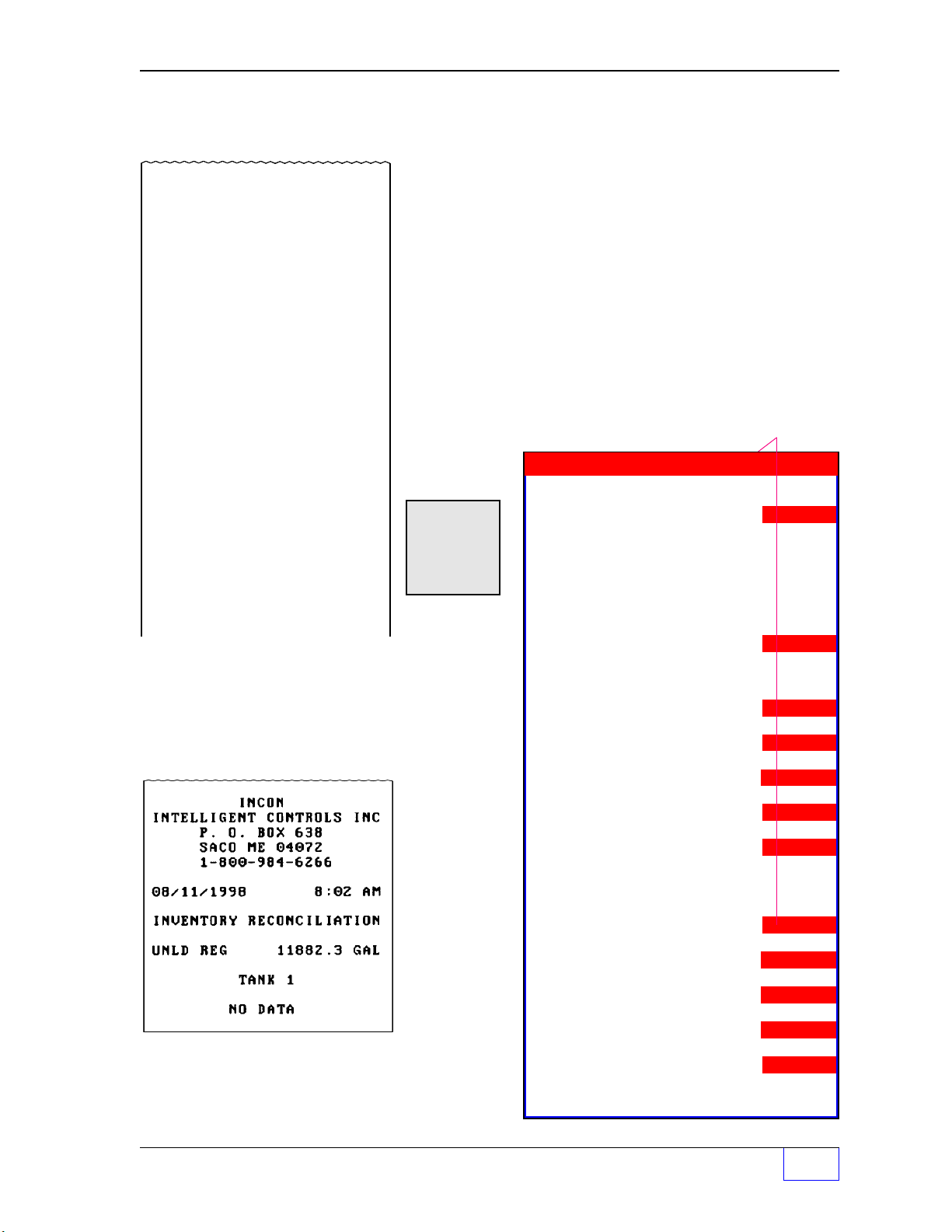
Product Usage Sales REPORT
INCON
INTELLIGENT CONTROLS INC.
P.O. BOX 638
SACO ME 04072
1-800-984-6266
3/12/2002 4:10 PM
SHIFT SALES
PROD 1 3000 GAL
TANK 1
RECON TIME 12:00AM
RCON DATE 01/01/
2002
SALES VOLUME
1756.5 GAL
SALES DOLLARS
1756.5 $
AVAERAGE PRICE 1.00 $
The Tank Sentinel DIM/Reconciliation option supports
Printing, Faxing and Transmission via a Serial Connection
Reconciliation reports that include Sales Volume data
collected from an attached TS-DIM unit.
The Sales Dollars Reports Feature adds the capability to
Print, Fax and Send via a Serial Connection Sales Dollars
reports. A Sales Dollars Report details the total sales in
gallons and dollars for each tank during a defined period of
time as well as the average price per gallon during the period.
Report Choices Press:
M4
Press:
JW
REPORT
9
Usage Reports:
Detail M1
+
Summary M2
Reconcile M3
Product Name
...Prod N
All
Choose Printer
or Fax
Choose Printer
or Fax
The report at left would be produced the first
time that a reconciliation report is scheduled to
print.
Tank Sentinel Reports Page 3 - 9
Shift M1
Daily M2
Monthly M3
History M4
Choose Printer
or Fax
Sales M4
Shift M1
Daily M2
Monthly M3
History M4
Choose Printer
or Fax
3
Page 45

Sample Reports (CONTINUED... )
Tank Leak Test Estimate REPORT
Shows the
estimated
amount of time to complete a Standard
/ Static Tank Leak Test if started immediately. Estimates
are affected by the size and type of tank, and conditions
within the tank (such as changing product temperature
because of a recent delivery, or surface ripples / disturbances
from a recent dispense or delivery). It also gives the time
remaining for a test if this is run during that test.
Dispensing or deliveries will affect leak tests ...false
results — increase, fail / leaks — will be produced.
Press: Press:
JW
REPORT
+
9
Test Reports:
Report Choices
M4
Estimate M1
Tank 1
…Tank N
All
Choose Printer
or Fax
Leak (Static Tank) M2
Line M3
Compliance M1
Test M2
History M3
Diagnostic M4
SCALD M4
(Tank Leak Test)
See next page for the Standard (Static)
and SCALD Tank Leak Test REPORTS.
3
Page 3 - 10 Tank Sentinel Operator’s Guide
Page 46
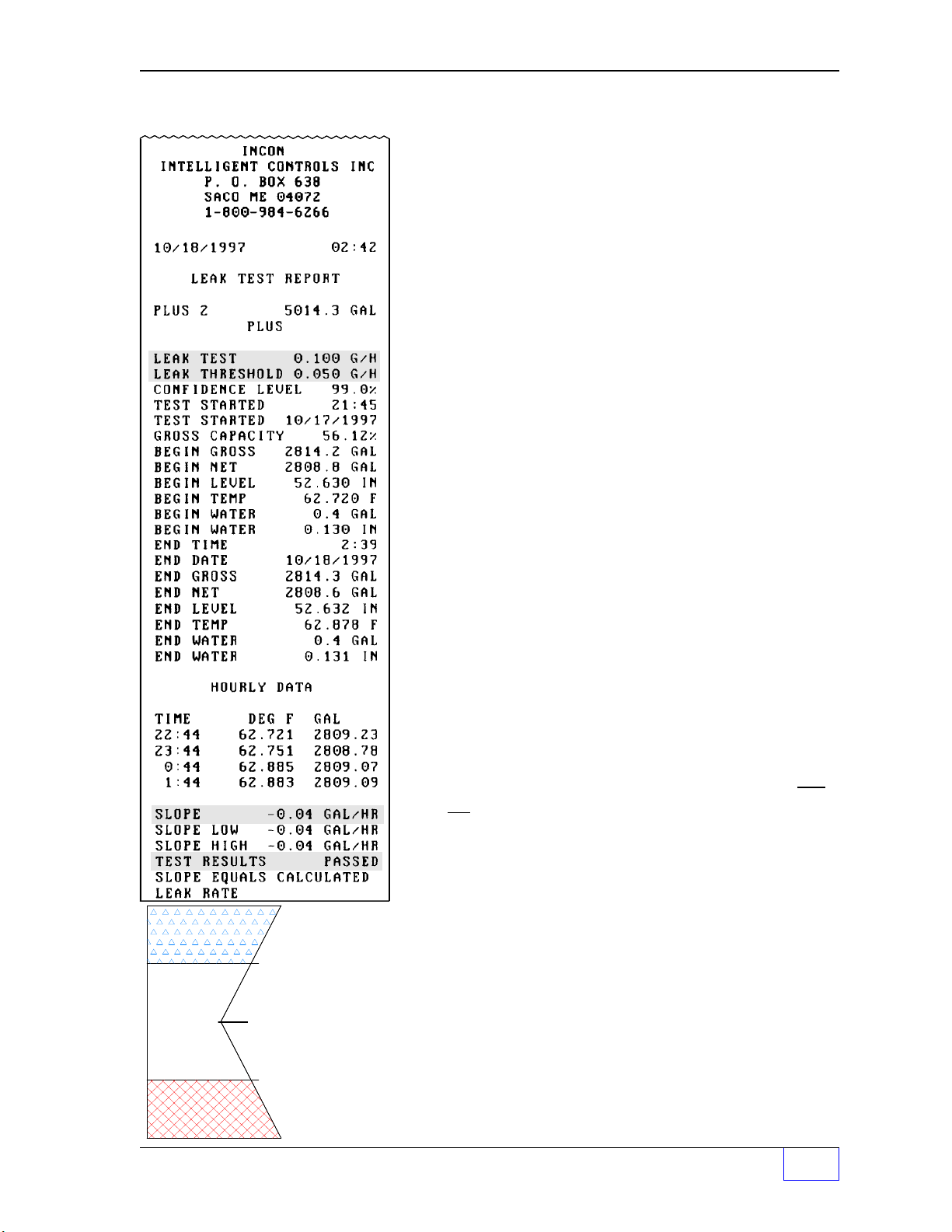
Standard (Static) T ank Leak Test REPORT
g
g
The data shown on the standard leak test report is:
1) Date and time that the report was produced (this can
be different from the test End Time and Date.
2) Tank name, number, and volume capacity (GAL).
Then the Leak Test Precision & Threshold is shown
(0.1 gph Annual Precision test — the default is the 0.2
gph monthly compliance test).
3) Test Confidence Level (here @ 99%... there is still a
1 % chance that the results are not accurate).
4) The test-START Time and Date
5) The Gross Capacity / percent full value in the tank
INCREASE
PASSED
FAILED
+ SLOPE
+ 0.10 gph
+ 0.05 gph
Leak Threashold =
Leak Test value / 2
Leak Threshold for:
0
a 0.20
Test = +/- 0.1
and for a 0.10 gph
Annual precision
Test = +/- 0.05 gph
- 0.05 gph
ph Monthly
- 0.10 gph
- SLOPE
ph,
6) BEGIN values
@ start of test (ie. G
ROSS
and NET)
7) The test-END (finish) Time and Date, and
8) The values @ END of the test (ie. T
EMP
and W
ATER
)
9) Hourly data (time, temperature, & net volume)
10) Slope is the (+/–) rate of change in product volume. It
is the calculated leak rate and is used to determine the
Test Result. Slope is affected by leaks, and by many
other sources of interference.
1 1) Slope Low and High is the amount of disturbance to the
leak test from temperature changes. Values close to each
other indicate that thermal expansion or contraction was
not a cause of interference. Values that are far apart will
cause an increase or indeterminate test result.
12) Test Results are either: Increase Passed Failed or
Indeterminate (if tests run 8 hours without a definite
result). See Chapter 4 about leak testing.
Slope & Leak Test Results
See the diagram to the left and the Leak Threshold value,
Slope value, and the Test Result line on Tank Leak Test
Reports. Slopes more negative than the threshold value
are reported as Failed, and those positive are reported as
Increase.
Tank Sentinel Reports Page 3 - 11
3
Page 47

Sample Reports (CONTINUED... )
SCALD Leak Test REPORT
SCALD is an acronym for Statistical Continuous Automatic
Leak Detection. This test is typically used at sites that
dispense 24 hours a day, where leak testing can only be
done between dispenses. It runs a 0.2 gph Monthly Regulatory
Compliance Test. The information that is shown on the
SCALD leak test report is:
1) Date and time is the time-stamp when the report was
produced (may not necessarily agree with the test
finished time and date
exactly when the test finished)
2) Tank name, Volume capacity (GAL) and Product name
3 ) Leak Test is the type of SCALD leak test (defult)
4 ) Leak Threashold is calculated by dividing the Leak test
setting by 2.
unless the report was printed
5 ) Interval is a diagnostic value used by technicians
6 ) Volume Qualify is the minimum percent required in the
tank for SCALD tank leak tests (regulations in some
areas may require a minimum 50 % full tank, or some
other percent full)
7 ) Test Started is the time and date when the SCALD leak
test started
8 ) Status is a diagnostic value used by technicians
9 ) Test Ended is the time and date when the SCALD tank
leak test finished
1 0 ) Slope is the (+/–) rate of change in product volume. It is
the calculated leak rate and is used to determine the Test
Result. Slope is affected by leaks, and by many other
sources of interference. See Chapter 4 for more
information about this. Also see Slope and Leak Test
Results on the proceeding page...
11) Test Results are either: Increase, Passed, Failed, or
NOTE
☞
3
Indeterminate
• See Chapter 4 & 5 about Leak Testing and Leak Alarms.
• The Leak Test Reports were produced on a tank gauge that was programmed with a
24 hour clock format.
Page 3 - 12 Tank Sentinel Operator’s Guide
Page 48

Line Compliance Test REPORT
(Intentionally shown out of position.) This report will include
one years worth of 0.2 gph monthly compliance tests for a
selected line, or all lines...
the most recent test is shown first
and the oldest last. After a year, the oldest test will be
dropped when a new test passes.
Press: Press:
JW
REPORT
+
9
Report Choices
M4
Test Reports:
Estimate (Tank) M1
Leak (Static Tank) M2
Line M3
Compliance M1
Line Name
…Line N
All
Choose Printer
or Fax
Test M2
Line Name
…Line N
All
Choose Printer
or Fax
History M3
Line Name
…Line N
All
Choose Printer
or Fax
Diagnostic M4
Line Name
…Line N
All
Choose Printer
or Fax
SCALD Leak M4
(Tank Leak Test)
Tank Sentinel Reports Page 3 - 13
3
Page 49

Sample Reports (CONTINUED... )
Line Leak Test REPORT
This report will show the latest line leak tests for a selected
line or all lines...
that passed today is shown first and is followed by the most
recent 0.1 or 0.2 gph line test result.
Note: Leak Rate is affected by many factors and is
provided for diagnostic purposes.
the number of passed 3 gph line leak tests
NOTE
☞
3
Line Leak Diagnostic REPORT
Not shown... this report is used by technicians to
diagnose problems.
See Chapter 4 & 5 about Leak T esting and Leak Alarms.
Page 3 - 14 Tank Sentinel Operator’s Guide
Page 50

Line Leak Test History REPORT
Tank Sentinel Reports Page 3 - 15
3
Page 51

Sample Reports (CONTINUED... )
...Shown in FAX format (page 1 & 3). The last 10 pass or failed line leak tests are shown per line.
Report(s) Sent to Remote Fax
Machines:
When properly setup, reports can be sent
automatically or manually to as many as
four different fax machines. Faxes are
arranged in a two column format, and will
fit on as many pages as necessary (as
shown here).
For example, Setup and Regulatory Reports
are lengthy and take many pages to finish.
The Tank Sentinel can transmit three pages
at a time. If a report requires more than 3
pages, then the console will call the remote
fax numbers repeatedly until all of the
pages have been sent.
3
Page 3 - 16 Tank Sentinel Operator’s Guide
Page 52

INCON
INTELLIGENT CONTROLS INC.
P.O. BOX 638
SACO ME 04072
1-800-984-6266
04/30/2002 10:08 AM
SENSOR STATUS REPORT
Sensor Status REPORT
Shows the Sensor name, the sensor input-channel number,
and the current status of each sensor that is wired to the
system
(OK or ACTIVE in alarm / leak detected).
Also, CVS
data will be shown on the report when CVS has been
programmed (enabled).
Press: Press:
JW
REPORT
+
Report Choices
M1
SENSOR NO. 1
SENSOR 1
OK
:
:
SENSOR NO. 7
SENSOR 7
STANDARD SENSOR ACTIVE
SENSOR NO. 8
SENSOR 8
LOW BRINE LEVEL ACTIVE
TANK COMPLIANCE
CVS TANK 1
SENSOR NO. 1
:
:
CVS TANK 4
SENSOR NO. 4
LINE COMPLIANCE
CVS LINE 1
SENSOR NO. 5
:
:
CVS LINE 4
SENSOR NO. 8
9
KX
DOWN
SP A CE
Sensor Reports:
Status M1
Choose Printer
or Fax
Vapor M2
Choose Printer
or Fax
Standard Sensor 7
is active / in alarm.
TSP-HIS Sensor 8
is active / in alarm.
Vapor Sensor # 5
is not in alarm.
Sensor 4 is assigned to
CVS Tank 4.
Sensor 5 is assigned to
CVS Line 1.
Vapor Sensor REPORT
Shows the Sensor name, the sensor input-channel number,
and the current detailed readings from each vapor sensor
that is wired to the system. RVU = Relative Vapor Units. The
sensor will alarm when the
greater than the
setpoint (OK or ACTIVE in alarm / leak
present
reading is equal to or
detected).
NOTE
☞
See Chapter 2 & 5 about Sensors and Sensor Alarms.
Tank Sentinel Reports Page 3 - 17
3
Page 53

Sample Reports (CONTINUED... )
y
y
y
y
y
y
Press
JW
REPORT
9
KX
DOWN
SP A CE
Alarm Reports:
System M1
Tank M2
Sensor M3
Line M4
All
# Press
DOWN
to
displa
ALL
Alarm Reports
+ Active System Alarms REPORT
Not shown... reports active system
warnings, alarms, and software — or
equipment hardware — failures, faults, and
errors. The date, time of the alarm, and the
alarm name are shown (typical).
M2
Cleared System Alarms
REPORT
Active
Cleared
Histor
Active
Cleared
Histor
*
Choose Printer
or Fax
*
Choose Printer
or Fax
Not shown... reports the system
alarms that have cleared.
System Alarm History REPORT
Not shown... reports all of the system
alarms (active, cleared and transient).
Active Tank Alarms REPORT
Not shown... reports active tank alarms
Active
Cleared
Histor
Active
Cleared
Histor
Active
Cleared
Histor
*
Choose Printer
or Fax
*
Choose Printer
or Fax
#
*
Choose Printer
M1
or Fax
by Tank... The date, time of the alarm,
and the alarm name are shown (typical).
Cleared Tank Alarms REPORT
Not shown... cleared tank alarms only.
Tank Alarm History REPORT
Not shown... reports all of the Tank
alarms (active, cleared and transient).
3
Page 3 - 18 Tank Sentinel Operator’s Guide
Page 54

Press
y
y
y
y
y
y
JW
REPORT
9
Alarm Reports (Continued... )
+ Active Sensor REPORT
KX
DOWN
SP A CE
Alarm Reports:
System M1
Tank M2
Sensor M3
Line M4
All
# Press
DOWN
to
displa
ALL
M2
Active
Cleared
Histor
Active
Cleared
Histor
Active
Cleared
Histor
Active
Cleared
Histor
Active
Cleared
Histor
Not shown... reports active sensor
alarms... The date, time of the alarm,
and the alarm name are shown
(typical).
Cleared Sensor Alarms
REPORT
Not shown... cleared sensor alarms
only.
*
Choose Printer
or Fax
Sensor Alarm History REPORT
Not shown... reports all of the sensor
alarms (active, cleared and transient).
*
Choose Printer
or Fax
Active Line Alarms REPORT
Not shown... reports active line
alarms. The date, time of the alarm, and
*
Choose Printer
or Fax
the alarm name are also shown (typical).
Cleared Line Alarms REPORT
Not shown... reports the line alarms that
have cleared.
*
Choose Printer
#
or Fax
M1
Line Alarm History REPORT
Not shown... reports all of the line
alarms (active, cleared and transient).
*
Choose Printer
or Fax
Continued next page...
Tank Sentinel Reports Page 3 - 19
3
Page 55

Sample Reports (CONTINUED... )
Alarm Reports (Continued... )
All Active Alarms REPORT
Reports all active system, tank, sensor, and line alarms.
The date, time of the alarm, and the alarm name are
shown (typical). The most recent alarms are shown first.
TSP-HIS BriteSensor 8
(Channel # 8) is in alarm (Low Brine Level).
Printer is Out of Paper alarm.
Standard Sensor 7
(Channel # 7) is in alarm.
Tank 1 (high product level) alarm.
The following example report is a scheduled Active Alarm
report where no active alarms exist.
This report cannot be printed manually from the keypad if no
data exists. The message NO ACTIVE ALARMS EXIST is
displayed in this case (or CLEARED in the case of Cleared
Alarm Reports).
All Cleared Alarms REPORT
Not shown... reports only cleared system, tank, sensor,
and line alarms.
3
Page 3 - 20 Tank Sentinel Operator’s Guide
Page 56

Alarm Reports (Continued... )
ENTER NUMBER OF ALARMS: NUMERIC
NNBACKSPACE
All Alarm History REPORT
Shows the history of all active, cleared and transient alarms
for all alarm types (System, Tank, Sensor, Line, or ALL). The
example to the left is an ALL — Alarm History report. It can
hold up to 50 alarms in the alarm history memory buffer. The
total number of alarms to print can be reduced to conserve
paper ...please see the Changing the Number of Reports
to Print topic earlier in this Chapter).
Changing the Number of Alarms to Print (in the
Alarm History Report)
Initially, the maximum number ( NN ) of alarms that can print
will be displayed. They are listed in chronological order with
the current alarms at the top and recent alalrms following in
order. The following display is shown when more than one
alarm can print:
M1 M2 M3 M4
Using the keypad, input a new number and press the
key to reduce the number of alarms to print (to conserve
printer paper)
– or –
simply press
ENTER
value displayed.
Tank Sentinel Reports Page 3 - 21
ENTER
to accept the
3
Page 57

Sample Reports (CONTINUED... )
System Setup REPORT
The System Setup report shows the full configuration of the
Tank Sentinel console. It includes most of the information
found in a tank setup report except for special tanks
strapping tables (tank chart) and information on special
tanks and products. See the following Tank Setup Report.
See an example system setup report on the following pages.
Tank Setup REPORT
Tank Setup Reports are available for each tank in the
system. The tank setup report includes all of the information
about a particular tank. The tank name, alarm limits, and
liquid level probe data, product data, and a strapping table
(tank chart). The strapping table print interval may be
selected when requesting this report.
Press:
JW
REPORT
+
9
KX
DOWN
SP A CE
Report Choices
Press:
M3
Setup Reports:
Setup M1
Choose Printer
or Fax
Tank M2
Tank 1
…Tank N
All (all tanks)
Choose Printer
or Fax
3
Page 3 - 22 Tank Sentinel Operator’s Guide
Page 58

Setup Report (example)
Tank Sentinel Reports Page 3 - 23
3
Page 59

Setup Report (example)
3
Page 3 - 24 Tank Sentinel Operator’s Guide
Page 60

Setup Report (example)
Tank Sentinel Reports Page 3 - 25
3
Page 61

Setup Report (example)
3
Page 3 - 26 Tank Sentinel Operator’s Guide
Page 62

Regulatory REPORT
This report can be sent to the regulatory agency for compliance
verification. It shows the hardware status of equipment that
is part of the INCON Tank Sentinel system. The last 12
months of
PASSED
Static and SCALD tank leak tests, and
passed 0.2 gph line tests are shown. In addition, the last 0.1
gph annual precision line leak tests for all lines are shown.
Also see Leak Test and Line Compliance Test reports.
Press: Press:
JW
REPORT
+
9
KX
DOWN
SP A CE
Report Choices
M4
Regulatory Report:
Regulatory M1
Choose Printer
or Fax
○○○○○○
○○○○○○○○○○○○○○○○○
Tank Sentinel Reports Page 3 - 27
3
Page 63

Sample Reports (CONTINUED... )
CPM Alarm Report
INCON
INTELLIGENT CONTROLS INC.
P.O. BOX 638
SACO ME 04072
1-800-984-6266
ALARM REPORT
2/1/2002 05:55 AM
CPM CURRENT LOW
2/1/2002 08:35 PM
CPM FAILURE
The CPM alarm report (at right) is generated when the current
level is below the setpoint, which is programmed. A CPM
failure will be produced if communication is lost between the
tank gauge and the TS-CPM unit (this may also be a result
to the TS-CPM loosing power). Alarm report(s) will only be
produced when SETUP> SYSTEM> REP ALARM> (report
alarms) is ENABLED.
Press: Press:
JW
REPORT
+
9
KX
DOWN
CPM Status Report:
Report Choices
M1
Alarm Status M1
Choose Printer
SP A CE
or Fax
INCON
INTELLIGENT CONTROLS INC.
P.O. BOX 638
SACO ME 04072
1-800-984-6266
ALARM REPORT
1/10/2002 08:02 AM
CATHODIC PROTECTION
VOLTAGE 15.0 V
CURRENT 10.0 A
STATUS OK
CPM Status Report
The CPM Status Report is available on demand for printing
at the tank gauge printer, or for faxing. A normal CPM Status
Report is shown at right. This time-stamped report shows the
voltage, current, and operational status for the unit, it would
show ALARM for the STATUS when in alarm.
It can be produced by:
• Pressing the REPORT key>
• DOWN key 2 or 3 times>
• Pushing the menu key (
below the
• Pushing
pushing
CPM
text>
M1
below the displayed
M2
below the displayed
M1
through M4) that is directly
PRINTER
FAX
text.
text, or by
3
Page 3 - 28 Tank Sentinel Operator’s Guide
Page 64

INCON
INTELLIGENT CONTROLS INC.
P.O. BOX 638
SACO ME 04072
1-800-984-6266
CPM Monthly Report
The Regulatory Report now includes a Monthly CP Status
Report, which is updated on the first day of every month. Up
to 12 months of Monthly CP reports are included in the
Regulatory Report (CPM must be enabled).
3/12/2002 4:10 PM
REGULATORY REPORT
:
MONTHLY CP
3/1/2002 12:00AM
VOLTAGE 15.0 V
CURRENT 10.0 A
STATUS OK
2/1/2002 12:00AM
VOLTAGE 15.2 V
CURRENT 9.9 A
STATUS OK
INCON
INTELLIGENT CONTROLS INC.
P.O. BOX 638
SACO ME 04072
1-800-984-6266
NOTE
☞
This report is available on demand for printing at the tank
gauge printer, or for faxing, or it can be sent via modem to
a site when the Regulatory Report is programmed properly.
A monthly CPM Status Report is shown at right. This report
can be automatically FAX’d to remote locations when the
tank gauge is equipped with an optional Fax-Modem. To do
this see the Comm Ports menu and Reports menu in the
Setup Programming Manual (INCON Part Number 000-
1053).
The TS-CPM programmed settings will appear on the
Setup Report. These are:
•
Enabled = YES or NO
•
Address = 112 (default value)
•
Current (Alarm Limit) = Programmed Value
•
Current OG
(output group) = Programmed OG
SYSTEM SETUP REPORT
:
CATHODIC PROTECTION
ENABLED YES
ADDRESS 112
CURRENT 8.0
CURRENT OG NONE
Tank Sentinel Reports Page 3 - 29
3
Page 65

Sample Reports (CONTINUED... )
y
y
Generator Run REPORT
INTELLIGENT CONTROLS INC.
INCON
P.O. BOX 638
SACO ME 04072
1-800-984-6266
6/17/2002 2:15 PM
GENERATOR RUN REPORT
INPUT
AUXILIARY 1
TANK 1 3918.47
GAL
PROD 1 #2 FULE OIL
BEGIN TIME 10:45 AM
BEGIN DATE 06/17/2002
BEGIN GROSS 3136.2 GAL
BEGIN NET 3129.4 GAL
BEGIN LEVEL 26.775 IN
BEGIN WATER 1.120 IN
BEGIN WATER 2 4.5 GAL
BEGIN TEMP 68.459 F
END TIME 11:58 AM
END DATE 06/17/2002
END GROSS 3118.3 GAL
END NET 3118.5 GAL
END LEVEL 24.875 IN
END WATER 1.120 IN
END WATER 24 .5 GAL
END TEMP 68.559 F
GROSS USAGE 1 7.9 G AL
NET USAGE 1 5.0 GAL
USAGE RATE 13.250 GPH
This report shows when the generator started (BEGIN)
and stopped (
USAGE RATE
END) and the fuel consumed (USAGE &
) during the run.
This report is available only with consoles that have the
special Emergency Generator application software.
Press: Report Choices
JW
REPORT
9
Generator Run Report:
Gen Run M1
M1
+
KX
DOWN
SP A CE
2 x
Press the
Displa
DOWN
ed with Emergency Generator
key to show this report.
Applications onl
Print T est REPORT
Press:
Choose Printer
or Fax
.
This report (at left without the standard header) checks
the operation and function of the printer. The printing
should be uniformly dark, clear, and legible.
MZ
Press: and
3
Page 3 - 30 Tank Sentinel Operator’s Guide
CHECK
.
M2
RIGHT
Page 66

— Your Notes —
—
Tank Sentinel Reports Page 3 - 31
❖
—
3
Page 67

4 Leak Testing
Contents:
Leak Testing — Overview
Tank Leak Tests – Type and Frequency
Requirements — Before Starting a Tank Test
When to Run Tank Leak Tests
Starting Tank Leak Tests
Tank Leak Test Results
Reasons Why Tank Leak Tests can Fail
All INCON Tank Sentinel models meet (or exceed) the requirements of the U.S.
Environment Protection Agency (EPA/530/UST-90/006 test protocol) for Automatic Tank
Gauging Systems (ATGS) for Monthly Monitoring for 0.2 gal/hr leaks of Underground
Storage Tanks. The system(s) also meet (or exceed) the requirements for Annual Tank
Tightness Testing for 0.1 gal/hr leaks of the National Work Group on Leak Detection
Evaluations (NWGLDE). Third Party Testing Laboratory test results (for standard [static]
tank leak tests) are also available upon request.
TS-LLD Line Leak Tests
Type and Frequency
Requirements, When to Run Line Leak Tests
Starting Line Leak Tests
When a Line Leak – Test Fails / is Detected
Steps to take When a Line Leak is Detected
Need Help ?
Overview
The tank gauge can be programmed to run automatic tank or line leak tests on a regular
schedule (either daily, weekly or monthly basis). In addition, leak tests can be started
manually from the console keypad – by using the
TEST
key.
To obtain valid results, leak tests should be started when conditions in the tank or line are
stable and will remain stable throughout the test
(such as during non-business hours).
A
test will not and can not pass when disturbed. Deliveries and dispenses will cause
thermal instability or product turbulence, which will interfere with and disturb a tank leak
test. These disturbances may cause the test to report a failure, or an increase result, or
cause the test to run for 8 hours and report an indeterminate test result.
Wait at least 6
hours after a product delivery, and 2 hours after product dispensing stops before
starting Tank Leak Tests.
Make sure there is enough time to run the test without interruption – print out a test Estimate
Report before running a tank test. Generally tank tests take about 4 to 5 hours to finish
(the exact time required depends on the size of the tank, volume in the tank, and the product
temperature).
The best time to test the tank integrity (leak test) is when it is full or nearly full. Regulatory
requirements in some areas insist on having a certain percentage in the tank before a test
can be considered valid and in compliance.
Try to run tests on tanks that are 50% full or
greater. SCALD leak tests can be programmed to run only when tank levels are at or above
a set value ( or percent full to qualify ).
Leak Testing Page 4 - 1
4
Page 68

Tank Leak Tests – Type and Frequency
Two standard leak tests can be started from the keypad, they are the 0.2 gph and the 0.1
gph test. Federal, State and local codes and regulatory agencies specify how often to run
these tests. Consult and comply with these rules and regulations.
CAUTION
reporting requirements of federal, state and local regulations. Your are legally bound to
follow these explicitly. Where they conflict with this manual, follow the regulations.
Requirements ✎✓
Before Starting a Standard (static) Tank Leak Test
Printout a leak test Estimate Report (Key strokes:
❐
Is there enough
❐
(Note: a 10,000 gallon tank requires about 5 or 6 hours to finish)
Wait at least 6 hours after a product delivery – or – 2 hours after a product dispense
❐
(Active tanks without Stage II vapor recovery may require longer stabilization periods).
NOTE
INCON does not recommend running both Line & Tank Leak Tests at the same time.
It is the tank owner’s obligation to comply with the procedures and the
quiet time
to finish the test ?
☞
When to Run Tank Leak Tests
REPORT — TEST —
(of no product dispensing)
M1
).
.
NOTE
☞
4
1) To comply with Federal, State, and local Regulatory Agency requirements.
2) To comply with the policy and procedures at your site.
3) Whenever a leak detection sensor alarms. This is especially important when a
discriminating BriteSensor detects a liquid / vapor hydrocarbon (product)... a failed leak
test and BriteSensor product alarm indicates a tank or product-line leak.
Standard / product alarms may be caused by motor oil runoff during heavy rains, or because
a BriteSensor has actually detected a product leak from a tank. Take a sample from the
area for chemical analysis.
Page 4 - 2 Tank Sentinel Operator’s Guide
Page 69

Starting Tank Leak Tests:
SELECT LEAK TEST OPTION
STATUS START ABORT
SELECT LEAK TEST TO START
0.1 TANK 0.2 TANK 0.1 LINE 0.2 LINE
SELECT TANK TO START 0.N TEST (MORE)
TANK 1 TANK 2 TANK 3 TANK 4
SELECT TANK TO START 0.N TEST (MORE)
ALL TANKS (N = 0.1 or 0.2 gph Tank Test)
Follow the steps below:
LY
TEST
0
M1 M2 M3 M4
LEFT RIGHT
1) Press the
2) Choose the type of test below (press a
TEST
key and then the
M2
key (above)
menu key
...choices are the 0.1 gph or 0.2 gph leak tests:
M1 M2 M3 M4
LEFT RIGHT
3) Choose the Tank # (press a
M1 M2 M3 M4
LEFT RIGHT
4)
or
press
DOWN
and the
menu key
menu key
below):
key under the
word ALL to choose ALL tanks:
)
Tank Leak Test Results
Leak test results are either increase, passed, failed, or indeterminate
Leak Test Reports, Slope & Leak Test Results in Chapter 3 of this manual)
Reasons Why T ank Leak Tests Fail:
•
Temperature instability – (temperature variations) of the product within the tank after a
delivery
is the most important and most common source of interference and failed leak
tests / false alarms
•
Temperature variation – of product within the tank (look at the hourly temperature data
on the leak test report and retest if the variation is more than a few tenths of a degree –
see Chapter 3).
M1 M2 M3 M4
LEFT RIGHT
(a failure to detect real leaks can also result).
Leak Testing Page 4 - 3
(see Tank
.
4
Page 70

Reasons Why Tank Leak Tests Fail (Continued... )
•
Large changes in product temperature (from start to end of the test).
•
Water Level changes (from start to end of the test).
•
Evaporation and loss of product – through the vent stack – will look exactly like a leak.
Evaporation can be a problem during high seasonal temperatures and/or high winds, &
when liquid level exposes the greatest surface area for evaporation (half full tanks are
worse). Seasonal variations in product composition, size of the tank (larger is worse), and
tank vent configuration are also evaporation factors.
•
Tank Deformation (the tank changes shape after a large product delivery)
•
Tidal Action in coastal communities may affect groundwater level and is another
source of tank deformation (certain times of the day – tide change inconsistently).
•
Tank Cross-Talk – level changes in one tank causes a level change in adjacent
tank or compartment.
•
Product Dispensing during a test
•
Actual Tank Leaks
When a Leak Test Fails
Leak tests do occasionally fail. A single failed leak test should not be a cause for great
alarm – don’t panic. Remember, if the confidence level of the test is 99%, there is a 1%
chance that the system will give a false answer.
NOTE
Don’t excavate / repair a tank because of a single failed leak test.
and procedures at you site / Chapter 5.
☞
If you fail a leak test, review the leak test report to determine if there is an obvious
source of interference with the test
4 for an example of a Tank Leak Test Report)
retest the tank as soon as possible. (Retest the tank to validate or invalidate the first
test result if no source of interference can be identified. If necessary, run several tests.)
If repeated tests indicate a leak and no obvious source of interference is found then
immediately have the tank precision / pressure tested. If the precision test confirms
the presence of a leak then you (the tank owner) must take corrective action in
accordance with federal, state and local regulations.
Reference the policy
(see the Causes of Leak Test Failures, and Chapter
. If such a source of interference is identified,
4
Page 4 - 4 Tank Sentinel Operator’s Guide
Page 71

WARNING
procedure requirements of federal, state and local regulations. These must be followed
explicitly. Serious legal, health and safety hazards could result from not taking immediate
and proper action. Where the codes and regulations conflict with this manual — follow the
regulations.
You (the tank owner) are legally obligated to comply with the reporting and
NOTE
Reference TABLE 5- 2 for a blank Test Schedule that you can copy and
use for Tanks, Lines, etc..
☞
TS-LLD Line Leak Tests:
Type and Frequency
Two line leak tests can be started from the keypad, they are the 0.2 gph and the 0.1 gph
test. Some jurisdictions recommend that a 0.1 gph annual precision line leak test be run
yearly. (The 0.2 gph test runs automatically on a daily basis. The coarse 3 gph line test
runs automatically after every dispense). State and local regulations may require more
frequent tests and inspections. Make sure
issues and requirements for compliance with these regulations.
CAUTION
reporting requirements of federal, state and local regulations. Your are legally bound to
follow these explicitly. Where they conflict with this manual, follow the regulations.
It is the tank owner’s obligation to comply with the procedures and the
your site personnel
are aware of all of the
Requirements ✎✓
Before Starting a Line Leak Test:
Create adequate quiet time:
❐
(bag or tape poly over dispenser & dispense lever). See test
0.1 gph precision test normally needs 4 hours of
❐
dispensing occurs before the test is started and takes 13 minutes to finish
0.2 gph test needs 13 minutes to 4 hours of
❐
When to Run Line Leak Tests
1) To comply with Federal, State, and local Regulatory Agency requirements.
2 ) To comply with the policy and procedures at your site.
3) When a leak detection sensor alarms – per policy and procedures at your site.
Stop dispensing / prevent dispensing
requirements below:
quiet time
quiet time
to finish
for the test
where no
Leak Testing Page 4 - 5
4
Page 72

Starting Line Leak Tests
SELECT LEAK TEST OPTION
STATUS START ABORT
SELECT LEAK TEST TO START
0.1 TANK 0.2 TANK 0.1 LINE 0.2 LINE
SELECT LINE TO START 0.N TEST (MORE)
LINE 1 LINE 2 LINE 3 LINE 4
SELECT LINE TO START 0.N TEST (MORE)
ALL LINES (N = 0.1 or 0.2 gph Line Test)
LY
TEST
0
M1 M2 M3 M4
LEFT RIGHT
1) Press the
2) Choose the type of test below (press a
...choices are the 0.1 gph or 0.2 gph leak tests:
M1 M2 M3 M4
LEFT RIGHT
3) Choose the Line # (press a
M1 M2 M3 M4
LEFT RIGHT
or
4)
word ALL to choose ALL lines
press
TEST
key and then the
DOWN
and the
M2
menu key
menu key
key under the
key (above)
menu key
below)
)
M1 M2 M3 M4
LEFT RIGHT
When a Line Leak Test Fails / Line Leak is Detected
The TS-LLD line leak detection system disables the Submerged Turbine Pump (dispensing
stops / is not allowed), the red Alarm light is flashed, and a flashing ALARM is displayed
under the LINE column, and an alarm report will printout.
is possible when one or more INCON TS-LLD line leak detectors are interfaced to the tank
gauge by the
CAUTION
TS-LLDI
interface.
Don’t excavate / repair a line because of a single failed leak test.
Confirm the presence of a leak before attempting any repairs !
NOTE
Leak tests occasionally fail when no leaks actually exist because of: product line
instability, thermal contractions within the line, or because of a pump / vapor recovery
☞
system malfunction. Air trapped within the line may also cause false leak alarms (this is
especially true after new installations / maintenance / service).
Automatic testing and reporting
4
Page 4 - 6 Tank Sentinel Operator’s Guide
Page 73

Steps to take When a Line Leak is Detected:
Reference the policy and procedures at you site / Chapter 5.
1) Identify what type of leak was detected
2) Stop / Prevent dispensing
3) Inspect the piping system, dispenser, fittings, and hoses for obvious leaks. Open
the dispenser enclosure, and inspect the fittings and fuel filter for leaks
especially
4) If no leaks are found during inspection, then start another leak test to verify
the previous failure.
5) If a leak is found, or if the second line leak test also fails, then:
a) Shut off all power to the affected pump and dispenser
b) Take corrective action in accordance with local, State, and Federal regulations
c) Contact the local inspection agency, and follow all procedures and
WARNING
the local inspection agency and comply with all of the reporting and procedure requirements
of local / State / Federal Laws and Regulations. These must be followed explicitly. Serious
legal, health and safety hazards could result from not taking the proper action. Where the
codes and regulations conflict with this manual, follow the regulations.
important if
instructions as required by State Laws and Regulations
When a line leak is detected, it is the station owner’s obligation to contact
(bag or tape poly over dispenser & dispense lever).
(this is
maintenance or service was done recently).
Need help ?
See the inside front cover of this manual for contact names / help with Tank or Line Leak
Test failures, with repeated failures, or with multiple Leak Test failures. Also see Chapter
5 for information about Alarms / Error Codes & Troubleshooting.
Leak Testing Page 4 - 7
4
Page 74

— Your Notes —
—
4
Page 4 - 8 Tank Sentinel Operator’s Guide
❖
—
Page 75

5 TroubleShooting & Routine Maintenance
(
)
(
)
p
g
q
y
g
g
(
g
g
)
y
(
y
)
Contents: Silencing Alarms
(see ACK key – Chapter 1, and
Acknowledging Alarms Chapter 2)
Alarms & Error Messages (TABLE 5 - 1)
System Test Schedule (TABLE 5 - 2)
Important Policy & Procedures at Your Site
(Silencing Alarms, Acknowledging Alarms,
Grace Period Allowed (# of times)
TroubleShooting
NOTE:
#
1
2
Diagnostic text
Printed / Faxed / Displayed
Alarm / Warning Text:
0.1 GPH LINE LEAK
DETECTED
0.1 GPH ABORT
in the left column, is shown
DISPENSE
Troubleshooting Alarms & Error messages,
Line and Tank Leak Test Failures
Call Numbers & FAX No’s (TABLE 5 - 3) )
DO
Before & After Installation / Upgrade
Site Sketch
Routine Maintenance (External Cleaning,
Replacing Printer Paper Roll, Fuses, &
Battery & Internal Cleaning)
TABLE 5 - 1
ALARMS & ERROR MESSAGES
bolded
Alarm Type:
LINE
LINE
{ become alarms if active for 48 hours }
System WARNING / Error Descriptions and
ALARM Descriptions
For LINE # N: Line Leak Detected / Leak Test
(1. Inspect dispense area for leaks 2.
Failed
Retest if no leaks seen 3. Shut off pump /
dispenser power
Attempted dispense causes the annual line leak
test to aborted
To allow dis
this test
/ TEST button on the TS-LLD Control Unit that is
flashin
Quick Reference Guide
Test and re
.
the 80 alarm-error-code.
(actions to take)
dispensing is not allowed during
ensing:
about the 0.1 gph Annual
uirements.
push the RESET
See the TS-LLD
0.1 GPH LINE LEAK
(Continued… )
0.1 GPH LINE TEST
3
ABORTED
4
0.2 GPH LINE LEAK
3 GPH LINE LEAK LINE
5
BLK TUB/LSU BLOCKED
6
TUBE
CU COMM/CU COMM
7
FAILURE
8
LINE OUT OF COMPLIANCE LINE
LINE
LINE
LINE
LINE
LINE
4. Second failure: Call Service provider / local
Regulatory Agency / Manager per policy
procedure at your site).
The annual precision line leak test was
intentionall
Gua
Follow the steps detailed above for 0.1
Leak Detected
LINE # N - Line Leak Detected / test failed Large /
gross leak
steps 3, 1, and 4 in this order).
Push RESET / TEST button on the TS-LLD
control unit that is flashin
and call for cleanin
Communications was lost between the Tank
Sentinel console and TS-LLD Control Unit
for service
33 or more da
leak tes has finished and passed
dispense attempts until the monthl
canceled / aborted from the Tank
e or from the TS-LLD control unit.
ph Line
(see above 0.2 gph line leak & follow
an 81 Alarm-error code
service).
…(call
.
s have passed since a 0.2 gph line
prevent
test passes
TroubleShooting & Maintenance Page 5 - 1
5
Page 76

TABLE 5 - 1 (CONTINUED... )
)
)
g
g
g
g
ALARMS & ERROR MESSAGES
NOTE:
#
9
10
11
12
13
14
Diagnostic text
Printed / Faxed / Displayed
Alarm / Warning Text:
LSU COMM/LSU COMM
FAILURE
LSU FAIL/LEAK SENSING
UNIT FAIL
ACKNOWLEDGED message A
ACTIVE message An ACTIVE Alarm or Warning exists
CLEARED message Formerly active Alarm or Warning has cleared
LEAK TEST: ABORTED
RESULT
in the left column, is shown
Alarm Type:
LINE
LINE
messa
bolded
{ become alarms if active for 48 hours }
System WARNING / Error Descriptions and
ALARM Descriptions
(actions to take)
(Push RESET / TEST button on the TS-LLD
control unit that is flashing an 83 Alarm-error code
and call for service
.
(Push RESET / TEST button on the TS-LLD
control unit that is flashing an 81 Alarm-error code
and call for service
warning
e Leak Test was aborted for Tank N
or
.
alarm
has been ACKNOWLEDGED
LEAK TEST: FAILED
15
RESULT
LEAK TEST: INCREASE
16
RESULT
LEAK TEST: PASSED
17
RESULT
LEAK TEST: INDETERMIN
18
RESULT (indeterminate)
message
messa
messa
messa
e
e
e
- Slope is less / more negative than the leak
threshold for Tank N
(see LEAK above - Retest &
See Chapter 3 & 4)
+Slope is more positive than the leak threshol d
value (= leak test/2) for Tank N
Retest and See Chapter 3 & 4)
Slope is less than leak threshold for Tank N
The leak test ran 8 hours but still can't determine a
result for Tank N
(some disturbance affected the
test... try again but wait 2 hours after the last
dispense, or 6 hours after the last delivery).
SENSOR FAIL / SNS FAIL /
19
SEN FAL
20
SYSTEM FAIL message Proceeds System Alarm Warning reports
21
TEST FAILED message
message Proceeds Sensor Fail Alarm reports
A Leak Test Failed result - for Tank and/or Line N
alarm report
(see LEAK,
22
TRANSIENT message
5
Page 5 - 2 Tank Sentinel Operator’s Guide
Brief Alarm or Warning that clears quickly /
automatically
Page 77

TABLE 5 - 1 (CONTINUED... )
ALARMS & ERROR MESSAGES
NOTE:
#
23
24
25
26
27
Diagnostic text
Printed / Faxed / Displayed
Alarm / Warning Text:
AUXILIARY INPUT SENSOR
CPM LOW CURRENT SENSOR
DRY WELL SENSOR
EXTERNAL INPUT SENSOR
HIGH BRINE SENSOR
in the left column, is shown
Alarm Type:
bolded
{ become alarms if active for 48 hours }
System WARNING / Error Descriptions and
ALARM Descriptions
Auxiliary input detected on channel 1 or 2
policy procedure at your site).
Current of Rectifier dropped below the threashold
value (a Tank Sentinel setting) (follow
policy procedure at your site)
TSP-MWS ground water Monitoring Well
BriteSensor is not submerged in water @ Channel
#N
(it cannot detect a product leak unless it's
submerged in ground water... the well may not be
deep enough or the sensor long enough... contact
service provider)
External N input module has detected an input
signal
TSP-HIS BriteSensor @ Channel #N detected a
High Brine level
leak] and call your local Regulatory agency. Shut
down pump & dispenser if a leak test has failed on
that tank and see procedures at your site.)
(follow policy procedure at your site).
(actions to take)
(Call service provider [to confirm
(follow
28
LIQUID DETECTED / LIQUID SENSOR
29
LOW BRINE SENSOR
PRODUCT PRESENT /
30
PRODUCT DETECTED
STANDARD ALARM /
31
STANDARD INPUT
NOTE
☞
Keep accurate and dated records, or printouts, of all alarms — when they happen and
when they clear.
Contact your Tank Sentinel service provider if the same alarms occur
often or repeatedly... multiple alarms are not normal.
TroubleShooting & Maintenance Page 5 - 3
SENSOR
SENSOR
Standard Sensor @ Channel #N detected a liquid
(run a tank leak test [depending on the sensor
location] and call service provider to identify the
liquid and retest sensor)
TSP-HIS BriteSensor @ Channel #N detected a
Low Brine level
leak] and call your local Regulatory agency. Shut
down pump & dispenser if a leak test has failed on
that tank and see procedures at your site.)
TSP-DIS, -DDS, -DTS, -MWS BriteSensor @
Channel #N detected Product / leak
provider [confirm leak] call the local Regulatory
agency. Shut down pump & dispenser for that
tank and see procedures at your site. [replace
sensor])
A Standard Sensor (type TSP-EIS, -HLS, -ULS) @
Channel #N has detected liquid
test [depending on the sensor location] and call
service provider to identify the liquid and retest
sensor)
(Call service provider [to confirm
(Call service
(run a tank leak
5
Page 78

TABLE 5 - 1 (CONTINUED... )
ALARMS & ERROR MESSAGES
NOTE:
#
32
33
34
35
36
Diagnostic text
Printed / Faxed / Displayed
Alarm / Warning Text:
SUMP FULL SENSOR
VAPOR DETECTED / VAPOR SENSOR
WATER DETECTED SENSOR
ALPHA ERROR / ALPHA ERR
/ ALPHA V
API ERROR / API VOL
in the left column, is shown
Alarm Type:
SYSTEM
SYSTEM
bolded
{ become alarms if active for 48 hours }
System WARNING / Error Descriptions and
ALARM Descriptions
TSP-DDS, -DTS BriteSensor @ Channel #N
liquid... Sump Full alarm
(actions to take)
(see site policy about
pumping containment sump waste water)
TSP-DVS BriteSensor @ Channel #N detected
product Vapor in the vapor monitoring well
service provider [to analyze the leak], call your
local Regulatory agency, and see procedures at
your site.)
TSP-DIS*, -DDS, DTS, DVS* Brit eSensor @
Channel #N detected Water, some sensors* may
not be able to detect product when water is
present
Error in API temperature compensation calculating
ALPHA (check any Special Products -- reprogram
temperature compensation type & API ALPHA
value).
Error in API temperature compensation routine
(check any Special Products -- reprogram
temperature compensation type).
(see procedures at your site)
(Call
37
CPM FAILURE SYSTEM
38
CPU CRASH SYSTEM
39
DATA ERROR / DIM SYSTEM
40
DATA NOT AVAILABLE / DIM SYSTEM
41
DIM COMM FAILURE SYSTEM
42
F14 OPEN / F14 FUS SYSTEM
FAX HARDWARE FAILURE /
43
FAX HW FAIL / FAX FAL
SYSTEM
No Power / Power is below 5 VDC - Check Power
Supply / Increase Voltage (if possible)
WARNING - Central Processing Unit / hardware
failure / power quality problem
Transient communication error between the Tank
Sentinel and TS-DIM unit. This alarm/error will
clear itself automatically.
Transient alarm/error caused when TS-DIM unit is
'busy' performing another task and cannot make
the requested data available until it is not 'bus y'.
This alarm/error will clear itself automatically.
Tank Sentinel has lost communications with the
TS-DIM unit. Verify power to the DIM / Verify
proper connection between DIM and console.
WARNING - FUSE F14 is blown... no 5 VDC
Sensor Supply Power. Leak detection sensors are
not working and cannot work without power
(call
service provider immediately to replace F14)
WARNING - Fax Hardware Failure... alarms &
compliance faxes cannot be sen t
(call servi ce
provider ASAP)
5
Page 5 - 4 Tank Sentinel Operator’s Guide
Page 79

TABLE 5 - 1 (CONTINUED... )
ALARMS & ERROR MESSAGES
NOTE:
#
44
45
46
47
48
Diagnostic text
Printed / Faxed / Displayed
Alarm / Warning Text:
FAX SND FAIL / FAX SND SYSTEM
FLOAT HEIGHT / FLOAT HT /
FLT HT
FLOAT MISSING / FLT
MISSNG /
LEAK SYSTEM
LEAK (Continued… )SYSTEM
LEVEL ERROR / LEVEL ERR
/ LVL ERR
FLT MIS
in the left column, is shown
Alarm Type:
SYSTEM
SYSTEM
SYSTEM
bolded
{ become alarms if active for 48 hours }
System WARNING / Error Descriptions and
ALARM Descriptions
WARNING - Fax Send Failure...
cable, call service provider... are the fax phone
numbers correct ?)
WARNING - Float Height - calculation Error
program error... call service provider)
WARNING - diagnostic warning Float Missing
service provider)
WARNING - a Leak detected @ Tank N during the
after hours Sentinel mode
see procedures at your site... 1. Shut off pump /
dispenser power 2. Retest / start a Standard 0.2
gph tank test for Tank N, 2 hours after the last
dispense
3. Second confirming failure: Call Service
provider / local Regulatory Agency / Manager per
policy procedure at your site or 4. Second Test
passes [false leak failure]... turn pump and
dispenser power back on and restore normal
operation.
WARNING - product Level - calculation Error
service provider to fix this problem)
3. Retest & See Chapters 3 & 4
(actions to take)
(check Dial tone,
(shut down dispensing,
(setup
(call
(call
MEMORY ERROR / MEM
49
ERR
50
NO PROBE /
51
PAPER OUT SYSTEM
POWER DOWN SYSTEM
52
53
POWER UP SYSTEM
54
PROBE SYNC /
NOTE
☞
NO PROB
PRB SYC
Keep accurate and dated records, or printouts, of all alarms — when they happen and
when they clear.
Contact your Tank Sentinel service provider if the same alarms occur
often or repeatedly... multiple alarms are not normal.
SYSTEM
SYSTEM
SYSTEM
WARNING - Memory Error (power quality problem,
or memory-backup battery is dead...
provider check / replace battery and verify that
unit works correctly as originally programmed)
diagnostic WARNING - No Probe Detected
PROB
(call service provider t o correct this
problem)
The printer is out of paper
thermal paper)
WARNING - Power Down (time that
power or was turned off
WARNING - Power Up (time that the unit was
powered up / regained power)
Diagnostic WARNING - signal lost from Probe
(
PRB SYC
call service provider if continuous)
(add new roll of TS-TP2
)
have service
NO
the unit lost
TroubleShooting & Maintenance Page 5 - 5
5
Page 80

TABLE 5 - 1 (CONTINUED... )
(
g
)
ALARMS & ERROR MESSAGES
NOTE:
#
55
56
57
58
59
60
Diagnostic text
Printed / Faxed / Displayed
Alarm / Warning Text:
RTC FAILURE SYSTEM
RTD TABLE ERROR / RTD
TBL ER / RTD TBL
SCALD TEST FAILED /
SCALD DETECTED LEAK
SEN DAT / SENS DATA /
SENSOR DATA ERROR
SENS LOSS OF SIGNAL /
SIG LOST / SE N SI G
SENSOR ID ERROR /
SENSOR ID / SENS ID
in the left column, is shown
Alarm Type:
SYSTEM
SYSTEM
SYSTEM
SYSTEM
SYSTEM
bolded
{ become alarms if active for 48 hours }
System WARNING / Error Descriptions and
ALARM Descriptions
Real Time Clock has failed. Clock and Calendar
settings are affected. Verify date and time are
correct (use CHECK key). Change settings as
needed. Cycle power. Verify settings (use CHECK
key).
WARNING - Number of RTDs Error does not
match actual / setup - programmed value
(actions to take)
service provider to correct this problem)
WARNING - SCALD Leak Test Failed alarm report
for Tank N
(run a Standard leak test for that
tank... See LEAK)
WARNING - a BriteSensor @ Channel #N is
sending data errors
WARNING - no data sent / signal lost from
BriteSensor @ Channel #N
(call service provider ASAP)
(call service provider
ASAP to correct this)
WARNING - a Standard sensor or BriteSensor
was incorrectly typed / identified
(call your service
provider to correct this)
(call
SENSOR SYNC ERROR /
61
SENSOR SYNC / SEN SYN
CORRECTION (STRAPPING)
62
TABLE ERROR / TABLE ERR
/ TBL ERR
TEMPERATURE ERROR /
63
TEMP ERROR /
THEFT DETECTED / THEFT
64
LIMIT
TS-SEM FUSE OPEN / SEM
65
FUS / SEM FUSE
UNSTABLE PROBE / UNST
PROBE / UNST PB / UNST
66
PB
VOLUME ERROR / VOLUME
67
ERR / VOL ERR
level, net, ulla
TMP ERR
e, water error
also see
SYSTEM
SYSTEM
SYSTEM
SYSTEM
SYSTEM
SYSTEM
SYSTEM
WARNING - data signals not synchronous from
BriteSensor @ Channel #N
(call service provider
ASAP to correct this)
WARNING - Tank Strapping Chart or Table...
setup Erro r (call service provider to co rrect)
WARNING - probe/product Temperature calculation Error (
TMP ERR
call service provider
to correct this problem)
WARNING - Sentinel Mode: Theft Detected (the
amount of product missing reached the Theft Limit)
alarm report for Tank N
WARNING - TS-SEM FUSE OPEN @ BriteBox #1
or #2... [#1 is closest to the console] there is no 5
VDC …Leak Detection Sensors wired to the
BriteBox won't function !
(call service provider to
troubleshoot/replace T S-SEM FUSE F1)
WARNING - the signal from Probe N has become
Unstable
WARNING - product - Volume calculation error
(call service provider to correct)
(Error in programming: tank shape / probe type /
special probe - OR - no level signal from probe.
Call service provider to correct this.)
5
Page 5 - 6 Tank Sentinel Operator’s Guide
Page 81

TABLE 5 - 1 (CONTINUED... )
ALARMS & ERROR MESSAGES
NOTE:
#
68
69
70
71
72
Diagnostic text
Printed / Faxed / Displayed
Alarm / Warning Text:
WATCHDOG TIMEOUT / WD
TIMEOUT
WATER VOLUME ERROR /
WTR VOL ER / WTR VOL
HIGH HIGH / HIGH HIGH
LIMIT
HIGH LIMIT TANK
LARGE THEFT TANK
in the left column, is shown
Alarm Type:
SYSTEM
SYSTEM
TANK
bolded
{ become alarms if active for 48 hours }
System WARNING / Error Descriptions and
ALARM Descriptions
WARNING - the console self-monitoring program
has detected a software or power quality problem
(actions to take)
(this error may happen after hardware upgrades)
WARNING - Water Volume calcul ation error
(Error in tank shape / probe type or special probe
data - OR - no water float / level signal from probe.
Call service provider to correct this.)
High High product level Limit @ Tank N
procedures at your site about this alarm / overfill)
High product level Limit @ Tank N
(see
procedures at your site about this alarm / overfill)
Generated by TS-DIM unit. The amount of product
dispensed exceeded the programmed User
Threashold value, and/or exceeded the number of
Dispensers in use. Also caused by a Catastrophic
Leak. (see policy procedures at your site)
(see
73
LOW LIMIT TANK
LOW LOW LIMIT / LOW LOW TANK
74
75
OVERFILL TANK
WATER LIMIT (or HIGH
76
WATER)
TANK
Low product level Limit @ Tank N
(see policy
procedures at your site)
Low Low product level Limit @ Tank N
(see policy
procedures at your site)
The overfill limit has been reached or exceeded .
Stop filling tank / Lower the product level.(see
policy procedures at your site)
The high Water level Limit has been reached or
exceeded @ Tank N
(see procedures at your site
about this alarm, is a Grace Period allowed ? how
many ?)
TroubleShooting & Maintenance Page 5 - 7
5
Page 82

TABLE 5 - 2
SYSTEM TEST SCHEDULE
Date
Monthly Hardware Check / Test
Results:
Pass / Operational
Fail / Trouble
Monthly Alarm
Annunciator(s)
Test
Results
Monthly Tank
Compliance
Leak Test
Results
(Tank N)
Monthly Line
Compliance
Leak Test
Results
(Line N)
NOTE
Contact your Tank Sentinel service provider if a hardware check finds a problem.
If a leak test fails, see Leak Testing Chapter 4 about leak testing before calling.
☞
The registered Tank Sentinel owner / operator may copy this page for reporting & documentation pur poses.
5
Page 5 - 8 Tank Sentinel Operator’s Guide
Page 83

Site Policy:
•
Silencing Alarms
(using the
•
Acknowledging Alarms
(see Chapter 2)... Policy and Procedures at your site:
ACK SHIFT
key — see Chapter 1)... Policy and Procedures at your site:
•
Grace Periods (Allowed when, number of times, etc.)
(see Chapter 2)... Policy and Procedures at your site:
TroubleShooting & Maintenance Page 5 - 9
5
Page 84

• Troub leshooting Alarms & Err or Messa ges
(see TABLE 5 - 1)... Policy and Procedures at your site:
5
Page 5 - 10 Tank Sentinel Operator’s Guide
Page 85

•
Troubleshooting Alarms & Error Messages (Continued...)
(see TABLE 5 - 1)... Policy and Procedures at your site:
•
Line and Tank Leak Test Failures
Policy and Procedures at your site (Who to call and when to call... also see inside
front cover of this manual):
TroubleShooting & Maintenance Page 5 - 11
5
Page 86

•
g
y
g
y
y
g
Call Numbers for Help
Policy and Procedures at your site (Who to call and when to call... also see inside
front cover of this manual):
TABLE 5 - 3 FAX Numbers & Location (Fill-in)
Fill-in FAX number
Fax # 1
Fax # 2
Fax # 3
Fax # 4
send Delivery reports to FAX #'s:
send all Alarm reports to FAX #'s:
send Leak (test) reports to FAX #'s:
send Line reports to FAX #'s:
send SCALD (tank test) reports to FAX #'s:
send Reports requested from keypad, or scheduled, to FAX #'s:
Fax numbers are programmed in the Setup mode (Com Ports menu), for the transmittal
of FAX reports durin
( )
( )
( )
( )
the normal run mode.
Identify Fax Machine Location
( )
( )
( )
( )
( )
( )
(Fax capability requires the optional TS-FM2 enabled) ...see example below:
Fill-in FAX number
Fax # 1
Fax # 2
Fax # 3
Fax # 4
send Deliver
send all Alarm reports to FAX #'s:
send Leak (test) reports to FAX #'s:
send Line reports to FAX #'s:
send SCALD (tank test) reports to FAX #'s:
send Reports requested from ke
Fax numbers are pro
of FAX reports during the normal run mode.
( 566-254-2180 ) Fuel Dispatch Service Company Inc.
( 566-254-2195 ) Service Compan
( 566-254-2121 ) Site Owner
( 576-257-1999 ) Re
reports to FAX #'s:
pad, or scheduled, to FAX #'s:
rammed in the Setup mode (Com Ports menu), for the transmittal
Identify Fax Machine Location
ional Office
( 1 2 3 4 )
( 2 3 4 )
( 3 4 )
( 3 4 )
( 3 4 )
( 1 3 )
NOTE
Before & After – Installation / Upgrade or a Change to Setup —
DO Printout or Fax a copy of the SYSTEM setup report and ALL
☞
TANK setup reports.
Keep the setup reports in a safe place should the system
setup be lost or erased (which would require another reprogramming of the system
setup).
5
Page 5 - 12 Tank Sentinel Operator’s Guide
Page 87

Site Sketch / paste-in area:
TroubleShooting & Maintenance Page 5 - 13
5
Page 88

Routine Maintenance
•
External Cleaning
Use a soft cloth, that’s moistened in a solution of mild detergent, to clean the outer
surfaces of the console.
•
Replacing the Printer Paper Roll
Replace the paper roll when colored stripes
appear at the outer edges of the paper, or
when a PAPER OUT warning is flashed at
the console display...
Use INCON part number TS-TP2
— 2 inch roll of thermal printer paper
1 ) Install the roll as shown to the right
2 ) Press the paper feed button to advance the
paper through the printer mechanism
3) Feed the paper through the output slot when
closing the printer bezel and keep a slight
tension on the paper while lowering the printer
bezel to its normal position. Make sure that
the paper is not pinched between the bezel (cover) and the enclosure.
Printer
Bezel
Paper
Feed B utton
Serrated paper cu tter
- paper output slot
TS-TP2
Thermal
Printer
2" paper r oll
NOTE
If you are installing a new roll after a PAPER OUT message is displayed, the unit will
print any reports that have been stored in memory. It will attempt to do this
☞
immediately
• Lubricate Printer:
Apply a dab of lubricant using a cotton swab to the printer shaft at the front of the
printer where the head moves across left and right — every year.
Routine Maintainance continued on the next page ...
after paper is fed through the printer.
5
Page 5 - 14 Tank Sentinel Operator’s Guide
Page 89

Routine Maintainance continued ...
• Replacing Fuses, Memory-backup Battery, & Interior Cleaning:
NOTE
Let your Certified Tank Sentinel service provider do this work for you !
☞
Fuse Replacement Instructions
See INCON document 000-0214 for Fuse Replacement Instructions.
NOTE
☞
WARNING
cause electrical shocks, injury, or death
inside the console.
CAUTION
the console before Replacing any Fuse !
Memory-backup Battery:
See INCON document 000-0210 for Instructions about testing and replacing the
battery.
CAUTION
backup Battery with the Tank Sentinel Console power on !
The
2 to 10 years, depending on the total number and length of all power outages
(3.2 to 2.8 VDC is okay). Check the battery voltage two years after
installation and thereafter, on a yearly basis. If battery voltage is too low,
the system will lose all programmed setup memory “configuration” when the
power is lost or turned off.
High Voltage(s) exist within the Tank Sentinel Console which could
if
all power is not turned off before working
Avoid electrical shocks — turned off all external power wiring to
Avoid loosing the setup program — Replace the Memory-
Life Expectancy
of the 3 Volt DC memory-backup battery can range from
Internal Cleaning:
Vacuum the interior of the console with nonmetallic brush – every year.
TroubleShooting & Maintenance Page 5 - 15
5
Page 90

— Your Notes —
—
5
Page 5 - 16 Tank Sentinel Operator’s Guide
❖
—
Page 91

FCC Information & Requirements
Contents
Overall Information & Requirements
INDUSTRY CANADA Information & Requirements
CP-01 Issue 8, Part I, Section 14.1
CP-01 Issue 8, Part I, Section 14.2
Overall Information & Requirements
This equipment complies with Part 68 of the FCC Rules. On the bottom of the
equipment exterior, near the telephone and serial ports, there is a label that
contains, among other information, the FCC Registration Number and the Ringer
Equivalence Number (REN) for this equipment. You must, upon request, provide
this information to your telephone company.
The REN is useful to determine the quantity of devices you may connect to your
telephone line and still have all those devices ring when you telephone numbers
is called. In most, but not all areas, the sum of the REN’s of all devices connected
to one line should not exceed five. To be certain of the number devices you may
connect to your line as determined by the REN, you should contact your local
telephone company to determine the maximum REN for you calling area.
If your telephone equipment causes harm to the telephone network, the Telephone
Company may discontinue your service temporarily. If possible, they will notify you
in advance. But if advance notice is not practical you will be notified as soon as
possible. You will be informed of your right to file a complaint with the FCC.
Your telephone company may make changes in its facilities, equipment, operations
or procedures that could affect the proper functioning of your equipment. If they
do, you will be notified in advance to give you and opportunity to maintain
uninterrupted telephone service.
Should you experience trouble with this equipment, please contact INCON
Technical Service, in the U.S.A., for repair or warranty information, at 1-80098INCON. If the equipment is causing harm to the telephone network, the
telephone company may request that you disconnect the equipment.
Only INCON certified technicians may make repairs to this equipment, please call
your local distributor for service or INCON Technical Service for assistance.
This equipment cannot be used on public coin phone service provided by the
telephone company. Connection to party line service is subject to state tariffs.
(Contact the state public utility commission, pubic service commission or corporation
commission for information.)
FCC Information & Requirements Page FCC - 1
FCC
Page 92

INDUSTRY CANADA Information & Requirements
CP-01 Issue 8, Part I, Section 14.1
“NOTICE: The Industry Canada Label identifies certified equipment. This certification
means that the equipment meets certain telecommunications network protective, operational
and safety requirements as prescribed in the appropriate Terminal Equipment Technical
Requirements document(s). The Department does not guarantee the equipment will
operate to the user’s satisfaction.
Before installing this equipment, users should ensure that it is permissible to be connected
to the facilities of the local telecommunications company. The equipment must also be
installed using an acceptable method of connection. The customer should be aware that
compliance with the above conditions may not prevent degradation of service in some
situations.
Repairs to certified equipment should be coordinated by a representative designated by the
supplier. Any repairs or alterations made by the user to this equipment, or equipment
malfunctions, may give the telecommunications company cause to request the user to
disconnect the equipment.
Users should ensure for their own protection that the electrical ground connections of the
power utility, telephone lines and internal metallic water pipe system, if present, are
connected together. This precaution may be particularly important in rural areas.
CAUTION
should contact the appropriate electric inspection authority, or electrician, as appropriate.”
CP-01, Issue 8, Part I, Section 14.2
“NOTICE: The Ringer Equivalence Number (REN) assigned to each terminal device
provides an indication of the maximum number of terminals allowed to be connected to a
telephone interface. The termination on an interface may consist of any combination of
devices subject only to the requirement that the sum of the Ringer Equivalence Numbers
of all the devices does not exceed 5.”
Users should not attempt to make such connections themselves, but
FCC
❖
Page FCC - 2 Tank Sentinel Operator’s Guide
Page 93

G Glossary
Contents:
Glossary of Technical Terms
(including Definitions and Explanations)
ABORT Stop or cancel a leak test before it has finished.
ACK
ALARM(s)
AST
ATG
AUTODIAL
BriteSensor™
C
An abbreviation for Acknowledge alarm. The ACK keypad key will silence alarms and is
used to acknowledge (become aware of) the existence and type of alarm when it is viewed /
displayed so that corrective action can be taken.
May occur in response to an abnormal condition (an external input signal, a detected
leak, a leak test failure, or when a set limit is reached). Alarms and warnings visually flash
the red alarm light or yellow warning light at the Tank Sentinel console. Alarm horn[s] / other
output devices can also be programmed to activate in response to alarms.
An abbreviation for Above ground Storage Tank.
An abbreviation for Automatic Tank Gauge (product level monitor & Leak Detection System.
A term to describe the programmed action of the Tank Sentinel console in response
to an alarm, delivery, or new leak test result... it can automatically dial the phone numbers of
remote modems (or fax machines) and send this information including reports (if the optional
Fax/Modem is present).
A special leak detection sensor that sends data to the Tank Sentinel console
about its identity, operating status, and the status of any alarm that it can detect.
An abbreviation for the international Celsius temperature scale.
CANCEL
selection.
CAPACITY
COM (or COMM)
CPM (TS-CPM)
CPU
CVS
DIM (TS-DIM) An abbreviation for Dispenser Interface Module.
DW
A keypad key that is used to back out / exit out of a menu or display, or to cancel a
95 % of the maximum liquid storage volume rating for a tank.
An abbreviation for communications (send or receive).
An abbreviation for Cathodic Protection Monitor.
An abbreviation for a Central Processing Unit of a computer (Tank Sentinel console).
An abbreviation for Compliance Via Sensors.
An abbreviation for a Double Wall storage tank.
Glossary Page G - 1
G
Page 94

DWT
An abbreviation for a Double Wall Tank.
EPROM
F
An abbreviation for the Fahrenheit temperature scale.
FLOAT
float position can be determined exactly along the length of the probe. Floats are designed to
float above products or below specific products but above water Two floats are used in
petroleum and similar applications where the product is
mix with water (is immiscible / insoluble). For these applications, a water-interface-float is
installed under the product float and is designed to float on water (in the region where the
water and product meet). The water volume is calculated and is subtracted from other various
calculations such as gross. A stainless steel float is used with special products and chemicals.
GRACE PERIOD
ACKnowledged.
GROSS
the probe (less water-volume). Gross product volume value is not temperature compensated,
and therefore, will fluctuate with the product temperature because of thermal expansion /
contractions. Product temperature equalizes / stabilizes several hours after a delivery in
underground storage tanks (USTs). After a delivery, wait six hours before manually starting
a leak test. The gross volume value is important in situations where the product is
than and does not mix with water (is immiscible / insoluble).
An abbreviation for: Electrically Programmed Read Only Memory computer chip.
One or two floats are installed on liquid level PROBEs. All floats are magnetized so the
both lighter than water and does not
The programmed time where normal operation will resume after an alarm is
The product-volume within a tank and is a calculated from the LEVEL measurement of
both lighter
HERTZ
HIGH BRINE
INTERSTITIAL SPACE
HYDROSTATIC INTERSTITIAL RESERVOIR
INDETERMIN
The alternating current (AC) frequency in cycles per second.
An alarm from a special TSP-HIS leak detection sensor. This sensor monitors
the brine for changes in level within the hydrostatic interstitial reservoir.
The space between double wall tanks (air or brine-filled).
Located above special DWTs. A brine solution
is added to the interstitial space of special double-walled tanks to a certain level in the
reservoir. The reservoir brine is monitored by the TSP-HIS BriteSensor for changes in level
(which should not occur). High or Low interstitial brine levels indicates: a water-leak into the
brine solution when ground water levels are high, or a brine-leak into the inner product
containment tank or into the environment (also see leaks and Chapter 2).
An abbreviation for INDETERMINATE leak test result (the leak test ran 8 hours
but could not calculate a definite result, which could be either a pass, fail, or increase, usually
because of wave action within the tank or because of product temperature fluctuations. Also
see the chapter about leak testing.
G
Page G - 2 Tank Sentinel Operator’s Guide
Page 95

LEAKS
Occur when holes develope in the tank wall or piping system, or when the seals around
tank accesses or pipe fittings age. The probability of a leak increases with age. There are two
types of leaks: 1.) Product contamination from high ground water levels, and 2.) Environmental
contamination from product leaking out of a containment area / tank. Leaks pollute the
environment and create serious health and safety hazards.
LEVEL
LOW BRINE
MAGNETOSTRICTIVE
MONTHLY COMPLIANCE
NET
OUTPUT GROUP / OUT GRP / OG
PERCENT
POS
PROBE
The actual physical height of the liquid in the storage tank in inches, or centimeters.
Level is determined by the position of the magnetized FLOAT on the probe.
An alarm from a special TSP-HIS leak detection sensor. This sensor monitors the
brine for changes in level within the hydrostatic interstitial reservoir.
Interaction of magnetic fields along a special conductor within the
probe and from the magnetic float that is used to measure exact distances / liquid level.
A regulatory requirement and proof thereof, for at least one passed
leak test per month (this is usually a 0.2 gph leak test).
The temperature compensated, product volume within a tank. NET is temperature
compensated per API standards (to 60 degrees F, or 15 degrees Celsius for petroleum products).
A collection of one or more alarms that are linked
together to control an output device (such as a horn or light).
The percentage of product within the tank in respect to the tank capacity.
An abbreviation for: a Point Of Sale terminal, or position.
A sensor-probe that is installed within a UST. The probe measures the product
TEMPerature from sensors within its’ shaft, and liquid LEVEL from the position of the FLOATs
along its shaft.
PROD
PROBE SYNC
QUIET TIME
RELAY
ROM (TS-ROM)
RTD
SCALD
An abbreviation for PRODUCT.
A term to describe a loss of synchronous data from the probe (usually because
of a stuck float, corroded, wet or broken cable wires, or probe failure).
The inactive period between dispenses.
A device that consists of an electrical solenoid coil, and mechanically-linked switch
contacts. When voltage is applied to the relay coil it activates like an electromagnet, and
moves the contact switch positions (off to on or on to off). Therefore, any device that is
wired to the relay contacts also turn on or off along with the control relay.
An external, 4 or 8 channel, Relay Output Module BriteBox that connects to
the console.... relay(s) can be activated in response to programmed alarms.
An abbreviation for the Resistive Temperature Detectors ... in a liquid level probe shaft.
An abbreviation for a special Statistical Continuous Automatic Leak Detection tank test
that runs continuously between the periods of product dispensing.
Glossary Page G - 3
G
Page 96

SEM (TS-SEM)
connection of 8 leak detection sensors.
An abbreviation for the external Sensor Expansion Module (BriteBox) for the
SENSOR SYNC
sensor (usually because of a corroded, wet or broken cable wires, or a sensor failure).
SENTINEL MODE
time must be programmed).
SETUP
SLOPE
STD
STP
SUMP
The programming / configuration mode of the Tank Sentinel console. Setup should be
password protected for operation, security, and compliance reasons.
The rate of change of product volume within a tank and can be either a positive or
negative (+/-) value. Slope is a value that is used in Tank Leak Testing to determine if a leak
exists or not. Slope is affected by leaks, product evaporation / vent loss, and by physical
interference and temperature fluctuations from dispensing or deliveries. Noise from other
tanks (cross-talk), leaky check valves in product-lines also disturb slope / leak tests results.
An abbreviation for a Standard leak detection sensor.
An abbreviation for Submerged Turbine Pump (the pump within the tank).
An underground containment area that is used to collect product spills (leak detection
sensors are usually mounted in these collection areas).
A term used to describe a loss of synchronous data from the leak detection
The after hours coarse leak test and theft monitoring mode (start and stop
TGI (TS-TGI)
TEMP
TRANSIENT
ULLAGE
UST
WD TIMEOUT
WTR LVL
The temperature of the product (from temperature sensors within the probe that are
submerged below the product level). Sensors above the product float level are excluded from
the probe temperature data set. Related subjects: GROSS, NET, PROBE and LEVEL.
without overfilling it (in gallons or liters). Ullage to full is 95% of the tanks total liquid volume
capacity. Also see CAPACITY.
An abbreviation for Underground Storage Tank.
quality problem... this will occur normally after an EPROM upgrade).
with petroleum based products or similar products, where a second and heavier water interface
float is installed on the probe
level units (inches, or centimeters).
An abbreviation for Tank Gauge Interface for / with line leak detectors.
A term used to describe an instantaneous alarm or fault such as a memory error.
The remaining gross capacity of a tank, or the volume that can be added to the tank
An abbreviation for a Watch Dog Timeout (temporary software failure or power
An abbreviation for the WATER LEVEL in the storage tank. This is applicable only
below the product float. Water level is displayed and printed in
WTR VOL
petroleum based products... where a second and heavier water interface float is installed on
the probe). Water volume is displayed in volume units (gallons or liters).
G
An abbreviation for water volume in the storage tank (this is applicable only in
—
Page G - 4 Tank Sentinel Operator’s Guide
❖
—
Page 97

CFF Customer Feedback Form
Your ideas and opinions are important !
Please help us improve our products,
services, and documentation by filling out
and answering this Customer Feedback
Form. Then return it to Franklin Fueling Sytems.
Please print these two pages and ll out information about yourself and the products you
have received. Use black ink and print clearly. Next, circle a ‘rating’ number for each
statement. Finally, write in your own comments and suggestions. Thank You!
Your Name (and Position):
Company Name:
Documentation & Manual Names:
Document & Manual Part Numbers:
Product - Model and Serial Numbers:
Street Address:
State and ZIP Code:
Franklin Fueling System Technical Support
3760 Marsh Road
Madison, WI 53718 USA
FAX #: 608-838-6433
Documentation and Manual rating:
Please circle (1 = no / poor, 2 = fair, 3 = okay, 4 = good, 5 = yes / excellent, N = don’t know)
The documentation is easy to use 12345N
Information is easy to nd 12345N
The Table of Contents is useful to nd data 12345N
Information is well organized 12345N
Information is clear and easy to understand 12345N
Information is complete and accurate 12345N
The illustrations are clear and easy to follow 12345N
The number of illustrations are adequate 12345N
&
Comments
Suggestions ? (please be specic)
Installation Date: Today’s Date:
Customer Feedback Form Page CFF - 1
CFF
Page 98

Sale and Supply Orders:
Please circle (1 = no / poor, 2 = fair, 3 = okay, 4 = good, 5 = yes / excellent, N = don’t know)
Your order was processed quickly 12345N
&
You were treated professionally
with respect 12345N
You received what you ordered on time 12345N
Sales Suggestions
Technical Service / Support
(Name of the service organization that you contacted ?):
Please circle (1 = no / poor, 2 = fair, 3 = okay, 4 = good, 5 = yes / excellent, N = don’t know)
Your call was processed quickly 12345N
Help and advice was professional
&
accurate 12345N
You were not kept on hold (for a long time) 12345N
Service / Support Suggestions
Your INCON system or product:
Please circle (1 = no / poor, 2 = fair, 3 = okay, 4 = good, 5 = yes / excellent, N = don’t know)
Operates well and as expected 12345N
You are pleased with your purchase 12345N
You would buy / recommend INCON products 12345N
Product Comments & Suggestions
Thank you for your help !
CFF
—
Page CFF - 2 Tank Sentinel Operator’s Guide
❖
—
Page 99

W
ARRANTY
INCON
workmanship for a period of 12 months of operation from the
date of installation, or 24 months from the date of shipment,
whichever occurs first. Tank Gauge Software, OEM equipment,
or non-serialized equipment that is sold by INCON (e.g. TS-M,
and TS-MLS) are warranted for 90 days, parts only. During the
warranty period, INCON will either replace or repair defective
product at no charge. Replaced or repaired products will be under
warranty for the remainder of the original warranty. This warranty
does not apply to equipment that is damaged by improper
installation, improper application, or that is damaged from abuse,
lightning, flood or explosion. A Return Material Authorization
(RMA) number is required for return of material. RMA numbers
are obtained from your: INCON Representative / Distributor, or
INCON-Certified Service Agency. INCON Technical Service
Department can also help you — Call at (800) 984-6266 or visit
our web page at
Warranty Disclaimer and Limitation of Liability
There are no warranties implied or otherwise that extend beyond
those specially stated here in this document. INCON disclaims
and excludes all implied warranties including without limitation
those pertaining to merchantability and fitness for a particular
purpose.
®
warrants its products to be free of defects in
www.incon.com for support.
NOTE
☞
INCON disclaims any liability for consequential or incidental
damages or breach of any expressed or implied warranty in
connection with this product or this manual including without
limitation: purchaser’s loss of power, loss of stored liquids, or
damage to the ground / underground or environment, whether
arising under theories of tort, negligence, strict liability, contract
or otherwise.
Some states do not allow the exclusion or limitation of incidental
or consequential damages or a limitation on the duration of implied
warranties, so the limitation or exclusion may not apply to you.
This warranty gives you specific legal rights, and other rights
which vary from region to region.
After installation, make sure to sign the completed Warranty
Registration form and return it to INCON. This form validates
the express warranty stated here !
Tank Sentinel Operator’s Guide
Page 100

Tank Sentinel Operator’s Guide
 Loading...