

Page 1
Tank Sentinel
®
Setup Programming
(TS- 1001, 2001, 504, & 508)
Automatic Tank Gauge
/
Leak Detection
System
Guide
Part Number: 000-1053, Rev. B
Copyright
©
January 2003
Page FC - 1
Page 2

NO TICE
INCON has strived to produce the finest possible manual for you, and to ensure
that the information contained in it is complete and accurate. However, INCON
makes no expressed or implied warranty with regard to its contents. INCON
assumes no liability for errors or omissions, or for any damages, direct or
consequential, that result from the use of this document or the equipment which
it describes.
This document contains proprietary information and is protected by copyright. All
rights are reserved. No part of this document may be reproduced in any form
without the prior written consent of INCON.
INCON reserves the right to change this document at any time without notice.
Need Help ? Contact INCON at:
INCON
INTELLIGENT CONTROLS, INC.
PO Box 638
SACO ME 04072
Office Hours: 8 a.m. to 5 p.m. EST Monday through Friday
Sales - Technical Service -
Phone: (800) 872-3455 Phone: (800) 984-6266
Fax: (207) 283-0158 Fax: (207) 282-9002
E-mail:
sales@incon.com
E-mail:
tech@incon.com
Visit our Website at: After Hours Cell Phone:
www.incon.com
(207) 229-4437
INCON is a wholly owned subsidiary of Franklin Electric and is a member of the
Franklin Fueling Systems Group
Tank Sentinel ® SCALD® Brite BriteBox® Britebus® BriteSensors
®
and INCON ® are registered trademarks of Intelligent Controls, Inc.
System Sentinel™ and System Sentinel ™ are trademarks of
Intelligent Controls, Inc.
Copyrighted 1997, 1998, 2003 Intelligent Controls, Inc. All rights reserved.
—
Tank Sentinel Setup Programming Guide
❖
—
Page 3

T able of Contents
P Preface................................................................................................... P - i
Graphic Symbol Conventions ..................................................................................... P - i
Page Numbering Convention ................................................................................. P - i
Page Layout Convention ....................................................................................... P - i
Before You Begin – Read This..................................................................................... P - ii
– Site Information Required ............................................................................. P - ii
– Other Sources of Information ....................................................................... P - ii
Scope of This Manual ................................................................................................. P - iii
Menu Conventions ......................................................................................... P - iii
Parent Menus ................................................................................................. P - iii
Key Action .................................................................................................................. P - iii
Alpha-Numeric Input............................................................................................ P - iv
Programming Alarms, Limits, or Inputs to Output Groups.......................................... P - v
Programming Output Devices: .................................................................................. P - vi
Example Applications: ......................................................................................... P - vi
Programming I/O Module Operation .............................................................. P - vii
Interfacing TS-LLD to Tank Gauge ............................................................................ P - vii
Leaving (Exit) Setup Programming .......................................................................... P - viii
After Programming is Done ...................................................................................... P - viii
Warranty Reminder .................................................................................................. P - viii
1 System Setup Programming................................................................ 1 - 1
System Menu .............................................................................................................. 1 - 1
2 T anks Setup Programming .................................................................. 2 - 1
Tanks Menu ................................................................................................................. 2 - 1
Tanks – TANK ALARM N Menu................................................................................... 2 - 3
Tanks – SPECIAL TANK N Menu ................................................................................ 2 - 5
3 Lines Setup Programming................................................................... 3 - 1
Lines Menu .................................................................................................................. 3 - 1
Line Data Menu ........................................................................................................... 3 - 2
4 Probes Setup Programming ................................................................ 4 - 1
Probes Menu ............................................................................................................... 4 - 1
Probes – PRESSURE Probe Data Menu ................................................................... 4 - 3
Probes – SPECIAL Menu ........................................................................................... 4 - 4
Table of Contents Page TOC - 1
TOC
Page 4

5 Products Setup Programming............................................................. 5 - 1
Products Menu ............................................................................................................ 5 - 1
SPECIAL PRODUCTS Menu ..................................................................................... 5 - 2
6 Manifolds Setup Programming............................................................ 6 - 1
Manifolds Menu ........................................................................................................... 6 - 1
Manifolds ALARMS Menu ........................................................................................... 6 - 2
7 Reconciliation SETUP PROGRAMMING.............................................. 7 - 1
Reconciliation Menu .................................................................................................... 7 - 1
8 Dispenser Interface Module (DIM) SETUP PROGRAMMING .............. 8 - 1
DIM Menu .................................................................................................................... 8 - 1
9 Reports Setup Programming............................................................... 9 - 1
Reports Menu ............................................................................................................. 9 - 1
Reports Schedule Menu ............................................................................................. 9 - 2
Tank Inventory Detail Report: .................................................................... 9 - 2
Tank Inventory Summary Report: ............................................................. 9 - 2
Product Inventory Detail Report: ............................................................... 9 - 2
Product Inventory Summary Report:......................................................... 9 - 3
Product Usage Detail Report: ................................................................... 9 - 3
Product Usage Summary Report: ............................................................. 9 - 3
Delivery Detail Report: .............................................................................. 9 - 4
Delivery Summary Report: ........................................................................ 9 - 4
Active Alarm Report: ................................................................................. 9 - 5
Cleared Alarm Report: ............................................................................... 9 - 5
Alarm History Report:................................................................................ 9 - 5
SCALD Leak Test: Report ......................................................................... 9 - 6
Sensor Status Report................................................................................ 9 - 6
Vapor Sensor: ............................................................................................ 9 - 6
Regulatory Report: .................................................................................... 9 - 7
Line Compliance Report: ........................................................................... 9 - 7
Line Diagnostics Report: ........................................................................... 9 - 7
Line Test History Report: ........................................................................... 9 - 8
Line Test Report:....................................................................................... 9 - 8
Shift Reconciliation Report: ....................................................................... 9 - 8
Daily Reconciliation Report: ...................................................................... 9 - 9
Monthly Reconciliation Report: .................................................................. 9 - 9
Shift Reconciliation History Report: .......................................................... 9 - 9
Daily Reconciliation History Report:........................................................ 9 - 10
Shift Sales Report: .................................................................................. 9 - 10
Daily Sales Report: ................................................................................. 9 - 10
TOC
Page TOC - 2 Tank Sentinel Setup Programming Guide
Page 5

Monthly Sales Report: ............................................................................. 9 - 11
Shift History Report: ................................................................................ 9 - 11
Daily History Report: ............................................................................... 9 - 11
1 0 Leak Test Setup Pr ogramming.......................................................... 10 - 1
Leak Test Menu (Static Tank) .................................................................................... 10 - 1
Tank Leak Test Menu................................................................................................. 10 - 2
1 1 SCALD ® T ank Leak T est Setup Programming.................................. 11 - 1
SCALD Tank Leak Test Menu..................................................................................... 11 - 1
SCALD (tank leak) Test Menu ....................................................................................11 - 2
1 2 Line T ests Setup Programming .......................................................... 12 - 1
LN (Line) Tests Menu ................................................................................................. 12 - 1
Line Leak Test Requirements & Notes: ..........................................................12 - 2
1 3 Clock / Calendar Setup Programming................................................ 13 - 1
Clock / Calendar Menu............................................................................................... 13 - 1
1 4 Annunciator Setup Programming ...................................................... 14 - 1
Annunciator Menu (Console Alarm Horn) .................................................................. 14 - 1
Annunciator Time-out................................................................................ 14 - 1
Modulated Annunciator Output Group (alarm assignment).................... 14 - 2
Solid Annunciator Output Group (alarm assignment) ............................ 14 - 2
1 5 Relays Setup Programming................................................................ 15 - 1
Relay Menu ................................................................................................................15 - 1
Relay 1 Output Group (alarm assignment) ............................................ 15 - 2
TEST Relay 1 ........................................................................................... 15 - 2
Relay 2 Output Group (alarm assignment) ............................................ 15 - 3
TEST Relay 2 ........................................................................................... 15 - 3
1 6 TS-ROM Relay Output Module Setup Programming ......................... 16 - 1
TS-ROM Menu ...........................................................................................................16 - 1
Grace Period .................................................................................................. 16 - 1
TS-ROM Channel 1 Output Group (alarm assignment) ..................... 16 - 2
TS-ROM Channel 2 Output Group (alarm assignment) ..................... 16 - 2
TS-ROM Channel 3 Output Group (alarm assignment) ..................... 16 - 2
TS-ROM Channel 4 Output Group (alarm assignment) ..................... 16 - 3
TS-ROM Channel 5 Output Group (alarm assignment) ..................... 16 - 3
Table of Contents Page TOC - 3
TOC
Page 6

TS-ROM Channel 6 Output Group (alarm assignment) ..................... 16 - 3
TS-ROM Channel 7 Output Group (alarm assignment) ..................... 16 - 3
TS-ROM Channel 8 Output Group (alarm assignment) ..................... 16 - 4
1 7 Sensors (Leak Detection) Setup Programming ................................. 17 - 1
Sensors Menu ............................................................................................................17 - 1
Naming Sensors .......................................................................................17 - 1
Leak Detection Sensors ........................................................................... 17 - 3
Standard Sensors (below... all Alarms = STD N) .....................................17 - 3
BriteSensors & alarms (all 3 wire – below)............................................... 17 - 3
1 8 Auxiliary Inputs Setup Programming................................................. 18 - 1
Aux. Input Menu .........................................................................................................18 - 1
1 9 Cathodic Protection Monitor (CPM) SETUP PROGRAMMING .......... 19 - 1
Remember:................................................................................................................. 19 - 1
CPM Menu Notes: ......................................................................................................19 - 1
2 0 I / O (Input/Output) Module Setup Programming.............................. 20 - 1
I O Module Menu ........................................................................................................20 - 1
Channel N Output Groups – Output Module Alarm Assignments ..............................20 - 4
2 1 Communication P orts Setup Programming ....................................... 21 - 1
Comm Ports Menu .....................................................................................................21 - 1
COMM PORT 2 Menu................................................................................................ 21 - 3
DATA MODE Menu..................................................................................................... 21 - 5
FAX MODE Menu ...................................................................................................... 21 - 8
2 2 Compliance Via Sensors (CVS) SETUP PROGRAMMING.................. 22 - 1
Remember:................................................................................................................. 22 - 1
Character input / editing: ............................................................................................22 - 1
Before Programming: .................................................................................................22 - 1
CVS Tanks Menu ............................................................................................22 - 2
CVS Lines Menu ............................................................................................22 - 3
2 3 Upgrade Menu ..................................................................................... 23 - 1
TS-UPGRADE ...........................................................................................................23 - 1
Upgrade Menu ................................................................................................23 - 2
TOC
Page TOC - 4 Tank Sentinel Setup Programming Guide
Page 7

2 4 Language Selection Menu................................................................... 24 - 1
Language Selection Menu ..........................................................................................24 - 1
Language Selection Notes .............................................................................24 - 1
2 5 Data Log Menu .................................................................................... 25 - 1
Data Log Menu ...........................................................................................................25 - 1
Data Logging Notes ........................................................................................25 - 1
2 6 Display Menu ....................................................................................... 26 - 1
Display Menu .............................................................................................................26 - 1
Display Notes .................................................................................................26 - 1
2 7 Problem Solving (Alarms & Errors) ................................................... 27 - 1
Problem Solving .........................................................................................................27 - 1
Outputs DON’T Turn On When Expected....................................................... 27 - 7
A Appendix A Standar d T anks................................................................ A - 1
B Appendix B Standard Products.......................................................... B - 1
C Appendix C Typical Tank Leak Test Times........................................... C - 1
D Appendix D P art Number Codes......................................................... D - 1
Tank Sentinel Part Numbering .................................................................................... D - 1
Example Part Numbers .................................................................................. D - 1
Part Number Codes & Meaning...................................................................... D - 2
CFF Customer Feedback Form........................................................... CFF - 1
FCC Information & Requirements ........................................................ FCC - 1
Overall Information & Requirements ...................................................................... FCC - 1
INDUSTRY CANADA Information & Requirements ............................................ FCC - 2
CP-01 Issue 8, Part I, Section 14.1 ............................................................ FCC - 2
CP-01, Issue 8, Part I, Section 14.2 ........................................................... FCC - 2
Table of Contents Page TOC - 5
TOC
Page 8

T able of FIGURES and T ABLES
Page Layout Convention ................................................................................. P - i
Figure 2 - 1 Typical Tank Limits....................................................................... 2 - 3
TABLE 4.1 SPECIAL PROBE RTD POSITIONS .......................................... 4 - 5
TABLE 9.1 TYPICAL REPORT SCHEDULE ................................................. 9 - 1
TABLE 9.2 24 HOUR TIME INPUT FORMAT .............................................. 9 - 1
TABLE 10.1 TYPICAL TEST SCHEDULE ................................................. 10 - 3
TABLE 10.2 24 HOUR TIME INPUT FORMAT .......................................... 10 - 3
TABLE 12.1 24 HOUR TIME INPUT FORMAT ...........................................12 - 2
TABLE 13.1 24 HOUR TIME INPUT FORMAT ...........................................13 - 2
WORKSHEET 1-1 – OUTPUT GROUPS - SYSTEM LIMITS ....................... 1 - 6
WORKSHEET 2-1 – OUTPUT GROUPS - TANKS 1 THRU 4 ...................... 2 - 8
WORKSHEET 2-2 – OUTPUT GROUPS - TANKS 5 THRU 8 ...................... 2 - 9
WORKSHEET 6-1 – OUTPUT GROUPS - MANIFOLDS 1 THRU 4 ............. 6 - 4
WORKSHEET 10-1 – OUTPUT GROUPS - TANK LEAK TESTS .............. 10 - 5
WORKSHEET 12-1 – OUTPUT GROUPS - LINE LEAK TESTS .................12 - 5
WORKSHEET 17-1 – OUTPUT GROUPS - SENSORS 1 TO 8 ..................17 - 4
WORKSHEET 17-2 – OUTPUT GROUPS - SENSORS 9 TO 16 ................17 - 5
WORKSHEET 17-3 – OUTPUT GROUPS - SENSORS 17 TO 24 ..............17 - 6
WORKSHEET 17-4 – OUTPUT GROUPS - SENSORS 25 TO 32 ..............17 - 7
WORKSHEET 17-5 – OUTPUT GROUPS - SENSORS 33 TO 40 ..............17 - 8
WORKSHEET 18-1 – OUTPUT GROUPS - AUX. INPUTS 1 AND 2...........18 - 3
WORKSHEET 19-1 – OUTPUT GROUPS - LINE LEAK TESTS .................19 - 3
WORKSHEET 20-1 – OUTPUT GROUPS - EXTERNAL INPUTS .............. 20 - 6
WORKSHEET 20-2 – OUTPUT GROUPS - LINE INPUTS .........................20 - 7
TOC
—
Page TOC - 6 Tank Sentinel Setup Programming Guide
❖
—
Page 9
P PREF ACE
Contents:
Graphic Symbol, Page #
& Layout Conventions
Before you Begin
– Site Information Required
– Other Sources of Info.
Scope of This Manual
Menu Conventions, Key
Action, Alpha-Numeric Input
Programming Alarm, Limits,
or Inputs to Output Groups
Programming Output Devices
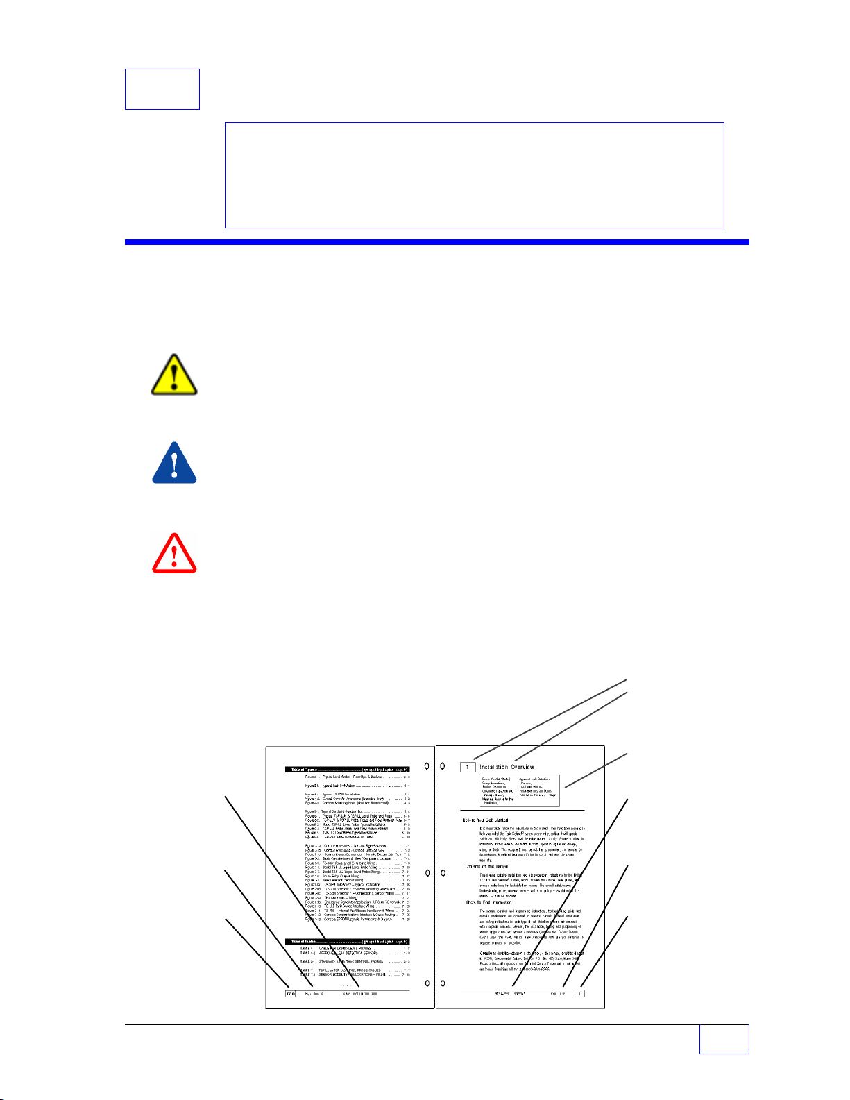
Graphic Symbol Conventions
NOTE
Important information, tips, and hints are highlighted by the NOTE graphic.
☞
CAUTION
instructions that must be followed to avoid faulty equipment operation, or hazards.
If ignored, equipment damage or personnel injury
WARNING
instructions that must be followed to avoid faulty equipment operation, or an explosion or
shock hazards. If ignored, severe injury or death
messages are highlighted by the
messages are highlighted by the
Programming I/O Module
Interfacing TS-LLD to Tank
Leaving (Exit) Setup
CAUTION
could
result!
WARNING
may
result !
Operation
Gauge
Programming
graphic and contain
graphic and contain
DANGER
messages are highlighted by the
that must be followed to avoid an explosion or electrical shock hazard. If ignored, severe
injury or death
will
result !
— ❖ — End of Chapter symbol
Page Numbering Convention – Example:
Page 4 - 1 = Chapter 4 page 1
Page Layout Convention – Example:
Manual Name
(
EVEN NUMBERED
PAGES
)
Page Number
Chapter Number
DANGER
graphic and contain instructions
Chapter Number &
Name (
FIRST
Chapter Contents
Chapter Name
(
Page Number
Chapter Number
TOP LEFT
PA GE
)
ODD NUMBERED
PAGES
)
PREFACE Page P - i
P
Page 10

Before Y ou Begin – Read This
CAUTION
Leaking underground storage tanks ( USTs ) and fuel lines cause serious
environmental and health hazards. The Tank Sentinel
in tanks by tank tightness / leak testing with liquid level probes, and/or with leak detection
sensors. You must follow the instructions in this manual carefully to ensure that the
system is programmed properly and is effective in detecting leaks.
– Site Information Required
• Site Plan? — showing the location, size, and model #s of all tanks, probes and sensors
• Dispenser Manufacturer Documentation?
• Pump Manufacturer Documentation? — Type, Model #s, and suction inlet
the bottom
of each tank (to determine the lowest product level and highest water level)
• Pump Control Required ? — enable / disable pumping... TS-IEM Output modules (for
TS-2001/508 consoles only), or a TS-ROM1 BriteBox
• Remote Device Control Required? — use TS-IEM (see above), or a TS-ROM2 BriteBox
• Remote Tank Overfill Alarm / Acknowledge Installed ? — (TS-RA1 or TS-RA2 / TS-RK)
Type, Model, Size and Manufacturer of each Tank
• Tank Manufacturers’ Tank Chart / Strapping Table (s)? — for each tank or the diameter
and length of each tank
• Are any tanks identical ? — (tanks, probe data, and alarm limits can be copied)
• Standard Probe Data? — (model number, shaft length, gradient, serial number)
• Special Probe Data? — (ie RTD / Temperature sensor locations)
• Tank # & Probe # — model number assignments and input channels for each tank
• Leak Detection Sensors? — installed in or near or associated with each tank including
input channel number assignments
• Product? — in each tank (API specific gravity) and the type & number of float(s) / probe
• State and Local Regulations? — (testing requirements, reporting requirements, and
hotline numbers, and other information that you and/or the customer will need)
®
system is designed to detect leaks
distance off
– Other Sources of Information
Use the TOC (Table of Contents) to find information within this manual and see the
following INCON documentation:
•
Installation Guide
•
Leak Detection Sensor – Installation Guides (one per type / family of sensor)
•
Tech Service Bulletins • Application Bulletins
P
Page P - ii Tank Sentinel Setup Programming Guide
•
Operator’s Guide
•
TroubleShooting Guide
•
Application Notes
Page 11
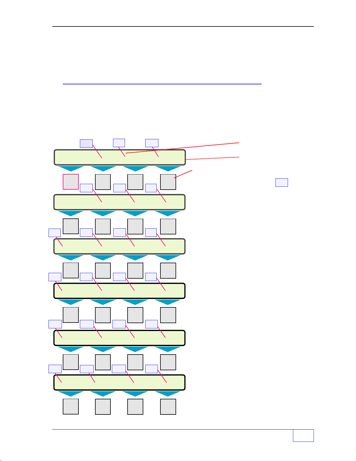
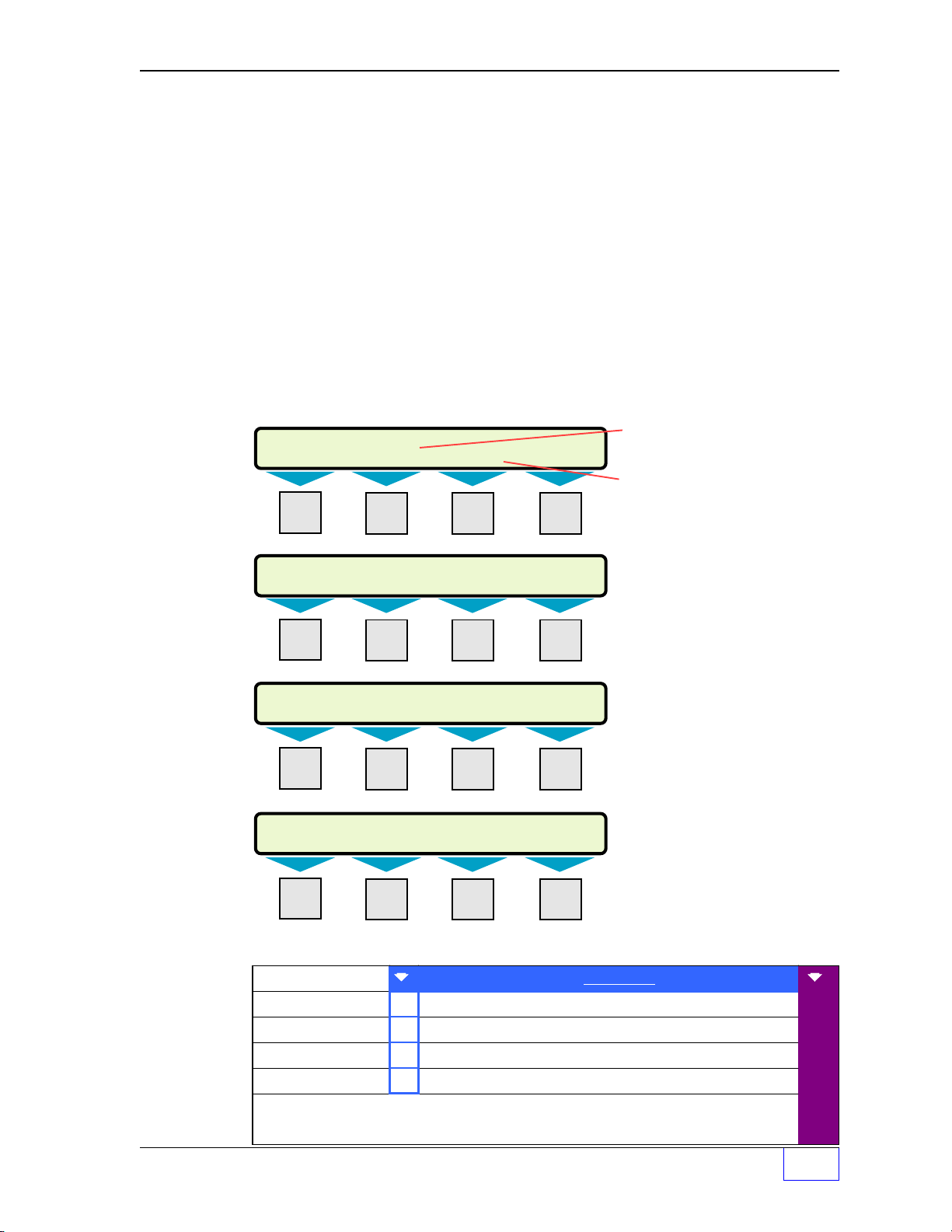
Scope of This Manual
SELECT MENU OPTION (MORE)
SETUP UPGRADE LANGUAGE DATALOG
SETUP MENU (MORE)
EXIT SYSTEM TANKS LINES
SETUP MENU (MORE)
PROBES PRODUCTS RECONCILE DIM
SETUP MENU (MORE)
REPORTS LK TESTS SCLD TEST LN TESTS
SETUP MENU (MORE)
CLK/CAL ANNUNC RELAYS SENSORS
SETUP MENU (MORE)
AUX INPUT CPM COM PORTS CVS
This manual shows the setup-programming of Tank Sentinel system. Each Chapter is
dedicated to a specific parent menu (see Parent Menus below).
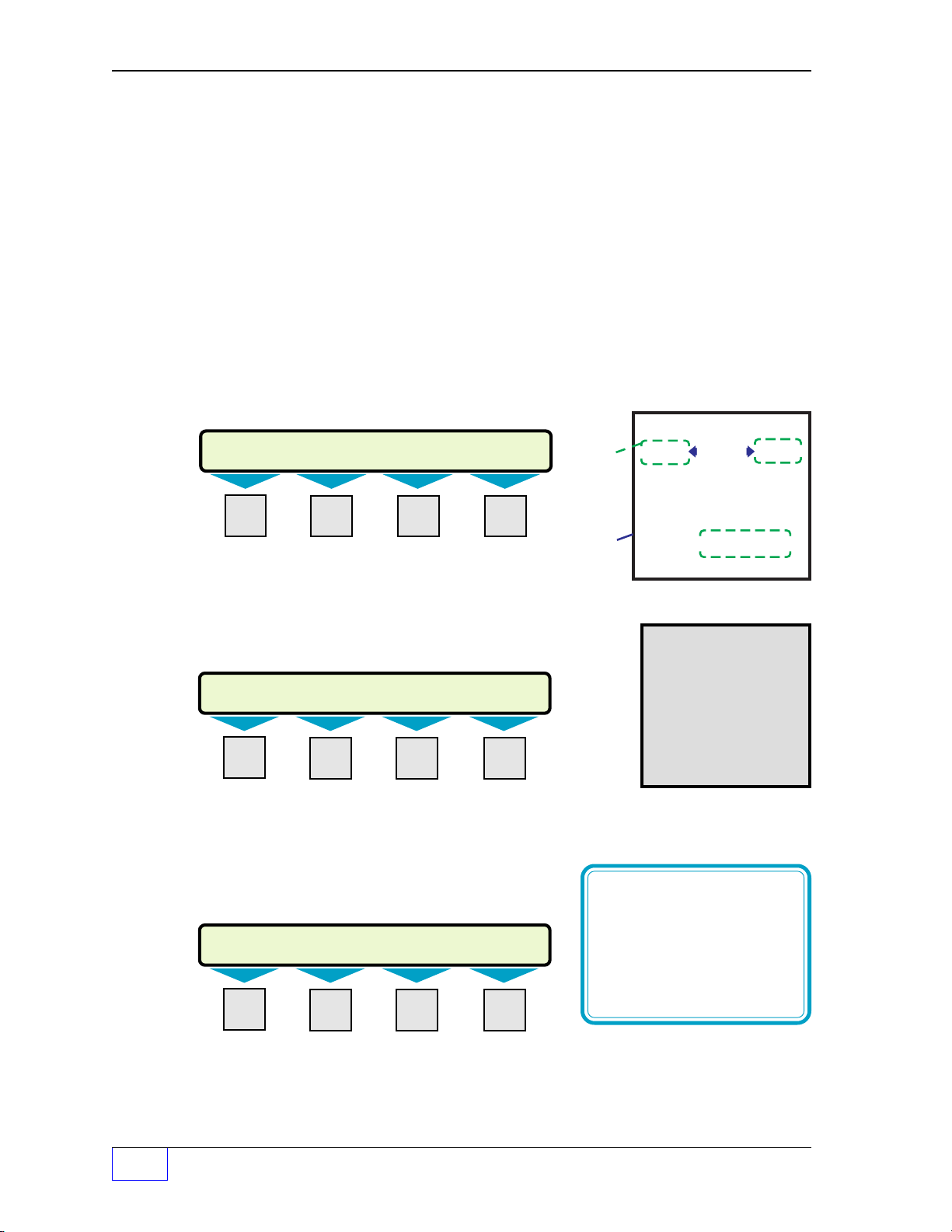
Menu Conventions
The menu structure in this manual is shown in an indented format:
PARENT MENUs are above and to the left of sub-menus and
SUB-MENUs are below and to the right of parent menus.
Default
Parent Menus
VALUES, SETPOINTS, & LIMITS
are shown first and in
ITALIC
text.
20
M1 M2 M3 M4
1 2* 3***
M1 M2 M3 M4
4*
8***
12
16
5* 6* 7
M1 M2 M3 M4
9*** 10*** 11
M1 M2 M3 M4
13 15*
M1 M2 M3 M4
17**
M1 M2 M3 M4
21
14**
18
22
19
UPPER ROW – DISPLAY TEXT
LOWER ROW – DISPLAY TEXT
MENU keys M1 thru M4
NOTES
☞
Numbers within boxes
Chapter #s. Some parent menus, or
are
sub-menus will not appear unless:
*
a related setup menu / feature is selected
**
the accessory (hardware) is installed and the
system is powered up
***
the appropriate options have been purchased
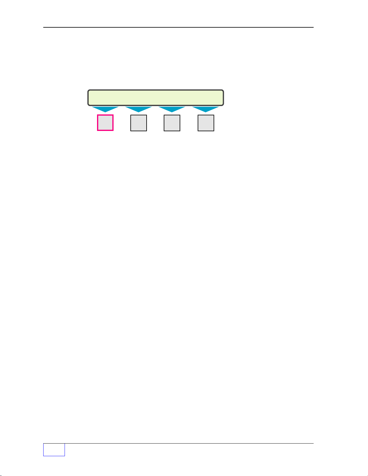
Key Action
MENU keys
•
choose / display other menus or sub-menus
or exit SETUP mode
•
move the cursor left or right through a text
string (
•
backspace over / delete a character in a text
string (
KEY PAD keys
•
ï
of a menu
•
▲
when (MORE) is shown, or other selections
from a sub-menu when (UP/DN) is shown
•
Use the
choice or value for storage into setup memory
– use (press) to:
M1
=
left, M2
M4
backspaces from the right)
– use (press):
CANCEL
UP
to cancel an input or to exit out
or
DOWN
ENTER
= right)
▼ to display more menus
key to accept the displayed
PREFACE Page P - iii
P
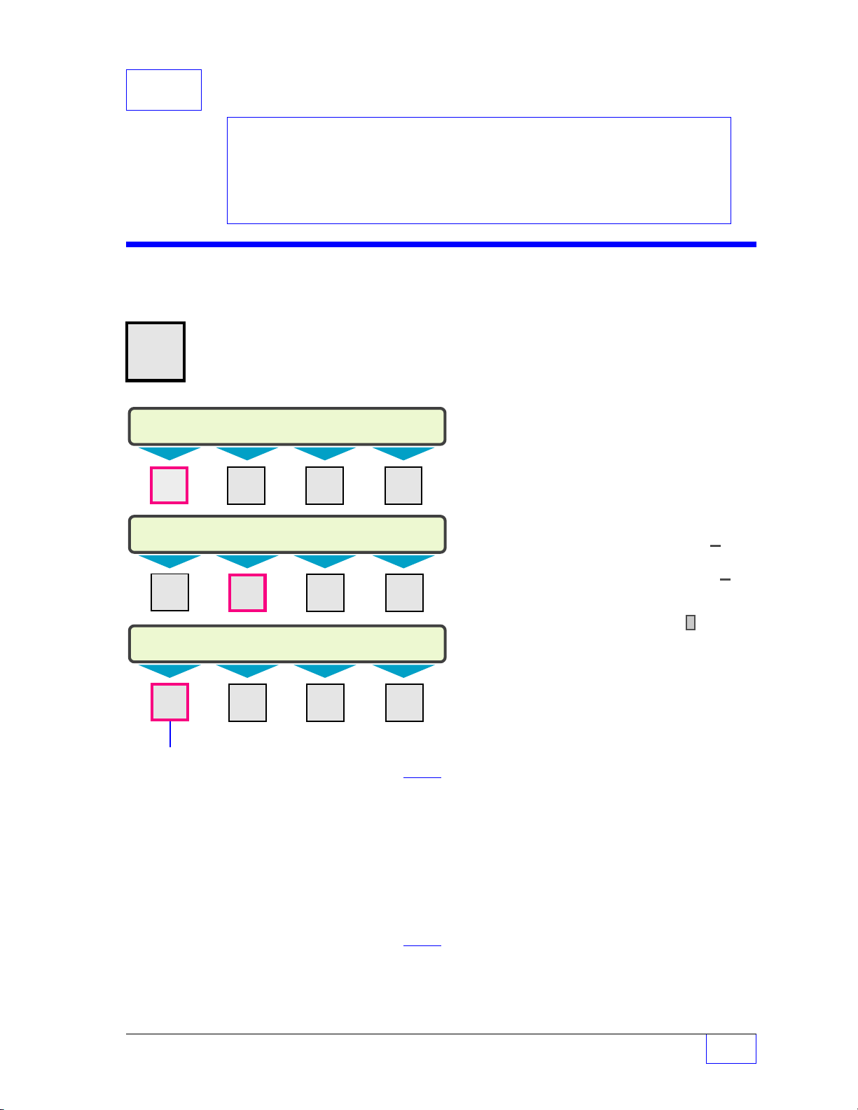
Page 12
Key Action (C
LOCATION LINE 1 A...M
INCON BACKSPACE
LOCATION LINE 1 N...Z
A BACKSPACE
LOCATION LINE 1 NUMERIC
AN 0.1 BACKSPACE
NOTE
The shift
function
will remain in the
current input character
mode (or position) until
the ACK SHIFT key is
pressed again
.
•
ONTINUED FROM PREVIOUS PAGE
ACK SHIFT
shows either an
key is used to change the preconditioned
A...M
expected. Press the
to another type (look at the upper right corner of display while doing this).
Operator’s manual about using the
and to start an output grace period (programmable length of time).
Alpha-Numeric Input (example)
The example below is what you would see when
programming SYSTEM ID... (press keys:
MENU M1 M2 M2 M1
M1 M2 M3 M4
... )
input character type...
or the word NUMERIC when an alphanumeric or numeric input is
ACK SHIFT key N
) to display:
times
to change the current input character type
ACK SHIFT
key to silence and acknowledge alarms,
Press the
N
Upper right
DISPLAY
shows the
input
selection
...shown
here
within
dashed
lines
times to DISPLAY the
input character type ( #__ )
then press the
(
)
# 1
A...M
COMMAND
the display
See the
ACK SHIFT
Key of choice.
(
input a
letter
# 2
N...Z
key
)
A...M means that the system is conditioned to
Typical
Key
(# 3)
number or special character
N
UMERIC
input the upper left letter of any key (A B C D
E F G H I J K L M)... see below:
Press
ACK SHIFT
key once again to display:
A
PRODUCT
M1 M2 M3 M4
1
N...Z means that the system is conditioned to
input the upper left letter of any key (N O P Q R S T U V W X Y Z)
– conditions remain until changed – see below:
Press
ACK SHIFT
key once again to display:
N
M1 M2 M3 M4
NUMERIC means that the system is conditioned to input the lower character of
any key (numbers 1 2 3 4 5 6 7 8 9 0 . +/– or a SPACE)... see above.
P
Page P - iv Tank Sentinel Setup Programming Guide
Page 13
Programming Alarms, Limits, or Inputs to Output Groups
HIGH PRODUCT OUTPUT GROUP 1 (UP/DN)
NONE
HIGH PRODUCT OUTPUT GROUP 1 (UP/DN)
GROUP A
HIGH PRODUCT OUTPUT GROUP 1 (UP/DN)
ALL GROUPS
TANK ALARM 1 (MORE)
COPY HIGH LIM H LIM OG HIGH HIGH
The TS-1001/504 / 2001/508 Tank Sentinels includes a powerful setup feature called –
Output Groups
assigned / programmed to output groups (OUT GROUP or OG). An output device will turn
on or off when an alarm is active in any of its assigned output group(s). Up to 32 output
group(s) can be assigned or programmed to any output device... also see Programming
Output Devices.
The
standard
optionally
output modules
508 consoles only.
Example: TANK 1, ALARMS and the H LIM OG (high product level limit) menus:
M1 M2 M3 M4
(OGs). Alarms, limits, and inputs (Aux. or
I/O
Module inputs) can be
output devices are annunciators and relays. Other
added to the system. These are: TS-ROM BriteBox
, and TS-IEM internal expansion PC Board
relays,
output modules
The HIGH LIM (high product
level limit) has an associated H
LIM OG – high limit output
group near it.
output devices
can be
TS-CIM BriteBox
— for TS-2001/
NOTE
☞
M1 M2 M3 M4
Each limit, alarm or input can
be assigned to one of the 34
Output Group choices —
GROUP A thru FF, or to ALL
M1 M2 M3 M4
M1 M2 M3 M4
Example Output Group Assignment WORKSHEET
OG = Output Group
Example - System:
LEAK OG
THEFT OG
SYSFL OG
Output Devices:
Modulated Annunciator, Solid Annunciator, Relay 1, Relay 2, I/O Output Module
Channel # 1 to # __ (record all OG Assignments in the vertical column)
- Output Group Assignment WORKSHEET Output Group choices -
= default setting (others are: GROUP A thru FF & ALL GROUPS)
NONE
Tank Leak turns on Modulated Annunciator, Relay 2 for external leak light
A
T
Sentinel Mode Theft Limit (turns on external product theft light)
System Fail - software or hardware failures - (activates solid annunciator)
F
output GROUPS, or to
( no output group = default )
Record output group
assignments for each alarm,
limit, or input in theprovided
OG Worksheets.
In an 8 tank system
there are 8
H LIM OG s (one under
each tank menu).
NONE
.
(partial)
NONE
A
B
C
E
F
PREFACE Page P - v
P
Page 14

Programming Output Devices:
After assigning alarms and limits to output group(s), program the appropriate
output devices to respond to any or all output groups (OGs)
Example Applications:
Turn on external Tank Overfill Alarm & solid console annunciator
(when a high or high high product level – alarm limit is reached)
Program the
LIM OG output groups to one alarm group for each tank
annunciator (alarm horn) and relay 1
(above)
alarm limits for each tank. Assign the associated H LIM OG or HH
(ie GROUP O).
output devices
to react to any
assignment... change GROUP O – (dash) to a Y. The external TS-RA2 or RA1 alarm unit
(wired to relay 1) will turn on / off
with relay 1.
This way a high level condition in any tank will activate the solid annunciator and the
external alarm connected to relay 1.
To disable a STP & turn on the modulated console annunciator
(when a low low product or high water – alarm limit is reached)
Program the
LIM OG output groups to a
1 & GROUP S for TANK 4)
N — OUT GRPS) to respond to a unique tank alarm
(above)
alarm limits for each tank. Assign the associated LL LIM OG and W
unique
. Program the TS-ROM channel relays
alarm group
for each tank (ie GROUP P for TANK
output device
GROUP __
. The line power, that
activates the STP motor relay, is wired between the TS-ROM relay contacts. When these
alarms occur, the unique output group activates the appropriate TS-ROM channel relay
which interrupts the STP power and disables dispensing.
Program the modulated annunciator (alarm horn)
output device
to activate and react to any
alarm by assignment... change GROUP P Q R S – (dash) to a Y.
Program the solid
GROUP O
alarm by
(CHANNEL
Example Output Device – OUTPUT GROUP Assignments
Output Device — OUTPUT GROUP Assignment
ABCDEFG H I JKLMNOPQRSTUVWX Y ZA AB BC CD DE EF F
Y YYY YYYYY Y
OUTPUT GROUP GROUP
Y – – Y Y Y – –– – – – – –Y Y Y Y Y
132
A B C D E F G H I J K L M N O P Q R S T U V W X Y Z AA BB CC DD EE FF
Press:M1 to move the cursor left
M2
to move the cursor right
UP / DOWN
ENTER
▲▼ to select (Y for yes assigned, or
to store the setup into the system memory
P
NOTE
☞
Page P - vi Tank Sentinel Setup Programming Guide
– – – – Y – – – – – – – – X
ï
ð
M4
to backspace (delete) one character to the left
–
(dash) for no not assigned)
(shown filled-in)
The 24TH group
(Group X) is shown
assigned
Y
ï
Page 15

Standard and
g
(
Optional
Output Devices
Standard Output Devices:
Modulated Annunciator
Solid Annunciator
Relay 1
Relay 2
Optional Output Devices:
TS-ROM Relay 1
TS-ROM Relay 2
TS-ROM Relay 3
TS-ROM Relay 4
TS-ROM Relay 5
TS-ROM Relay 6
TS-ROM Relay 7
TS-ROM Relay 8
: The TS-2001 will list the
Note
TS-CIM Output Modules as I/0
Module - Outputs # 17 throu
if installed).
# 24
h
Optional (TS-CIM / TS-IEM) Output Devices
I/O Module Output 1*
I/O Module Output 2*
I/O Module Output 3*
I/O Module Output 4*
I/O Module Output 5*
I/O Module Output 6*
I/O Module Output 7*
I/O Module Output 8*
I/O Module Output # 9* I/O Module Output # 10*
I/O Module Output # 11* I/O Module Output # 12*
I/O Module Output # 13* I/O Module Output # 14*
I/O Module Output # 15* I/O Module Output # 16*
I/O Module Output # 17* I/O Module Output # 18*
I/O Module Output # 19* I/O Module Output # 20*
I/O Module Output # 21* I/O Module Output # 22*
I/O Module Output # 23*
I/O Module Output # 24*
:
Programming
I/O
Module Operation
The TS-CIM / TS-IEM channels * can function either as an input or an output module. The
mode menu option allows selection of the channel operation — this must correspond to the
type of module that is inserted into the channel. Input mode must be selected for input
modules, and output mode must be selected for output modules.
about
NOTE
☞
IO MODULE
Aux. Inputs are always inputs and cannot be changed because the input circuitry
is hard-wired. Reference the Chapter about
setup programming.
Interfacing TS-LLD to Tank Gauge
In order to interface the INCON TS-LLD line leak detector(s) to the TS-1001/504 / 2001/
508 Tank Sentinel consoles —
Use the
communication). The first TS-LLD is wired to the tank gauge and the others are connected
to each other (1 to 2, 2 to 3... ).
1.10 and higher ( check options – L must be in the part number ).
TS-LLD
interface terminals within the console (providing RS-485 bidirectional
LLD
Reference the Chapter
AUX INPUT
setup programming.
is available with Tank Sentinel software version #
PREFACE Page P - vii
P
Page 16
Leaving (Exit) Setup Programming
SETUP MENU (MORE)
EXIT
SYSTEM TANKS PROBES
There are two ways to leave the setup mode. These are:
NOTE
☞
1.) Use (press) the
exit the setup mode.
M1 M2 M3 M4
2.) Wait until the Tank Sentinel console
The unit will automatically leave / exit the setup mode
of inactivity (if no key is pressed). This feature prevents the unit from being left in the setup
mode for long periods of time...
the setup mode.
While viewing data in the normal run mode, the display will also revert to the normal display
after shorter period of key inactivity (20 or 30 seconds).
CANCEL
key until the exit choice appears, then press the
– or –
M1
key to
autoexits
leak testing and leak detection are not active while in
.
( autoexit )
after three or four minutes
After Programming is Done
After the system is custom-programmed and tested, printout or Fax a hard copy of the:
system setup report, and a setup report for each tank for your records. Please give a
copy of these reports to the customer for his records.
Warranty Reminder
After installation, make sure to sign the completed Warranty Registration form and
return it to INCON. This form validates the express warranty stated here !
—
❖
—
P
Page P - viii Tank Sentinel Setup Programming Guide
Page 17
1 System SETUP PROGRAMMING
SELECT MENU OPTION (MORE)
SETUP
UPGRADE LANGUAGE DATALOG
SETUP MENU (MORE)
EXIT
SYSTEM
TANKS LINES
SYSTEM INFO (MORE)
PASSWORDS SYSTEM ID UNITS NO. TA NKS
Contents:
System Menu
Worksheet 1-1 — System Output
Groups
System Menu
H U
MENU
7
× Press this key and follow the
highlighted sequence shown below
M1 M2 M3 M4
NOTE
☞
See the Table of Contents to find topics in
this manual. See the Preface for general
information about this manual. See the
Installation, Operator’s, TroubleShooting
Guides and Application Notes for other
reference sources.
The NO. (of) TANKS set in the system menu
is shown in the TANKS, PROBES and
PRODUCTS menus !
Remember:
• Use
• Press
• Use the
UP
or
DOWN
▲ ▼ key to display
more menus (MORE shown) or selec
tions (UP/DN shown)
CANCEL
ENTER
to cancel data entry
key to accept data
Character input / editing:
• Press
• Use
M1 M2 M3 M4
• Press
M1 M2 M3 M4
PASSWORDS
(none / empty)
(Secures access to setup mode or acknowledging alarms and/or starting grace periods.
A setup password is recommended for security.)
SETUP
SETUP PASSWORD
ACK
ACKNOWLEDGE PASSWORD
(none / empty)
enter up to 12 characters max.
Press
ENTER
(also see ANNUNC [IATOR] menu for time-out)
enter up to 12 characters max.
Press
ENTER
to accept this data.
to accept this data.
M1
to move the cursor left
M2
to move the cursor right
M4
to backspace (delete) one
or more characters to the left
ï
ð
ï
— Continued on next page —
System Setup Page 1 - 1
1
Page 18
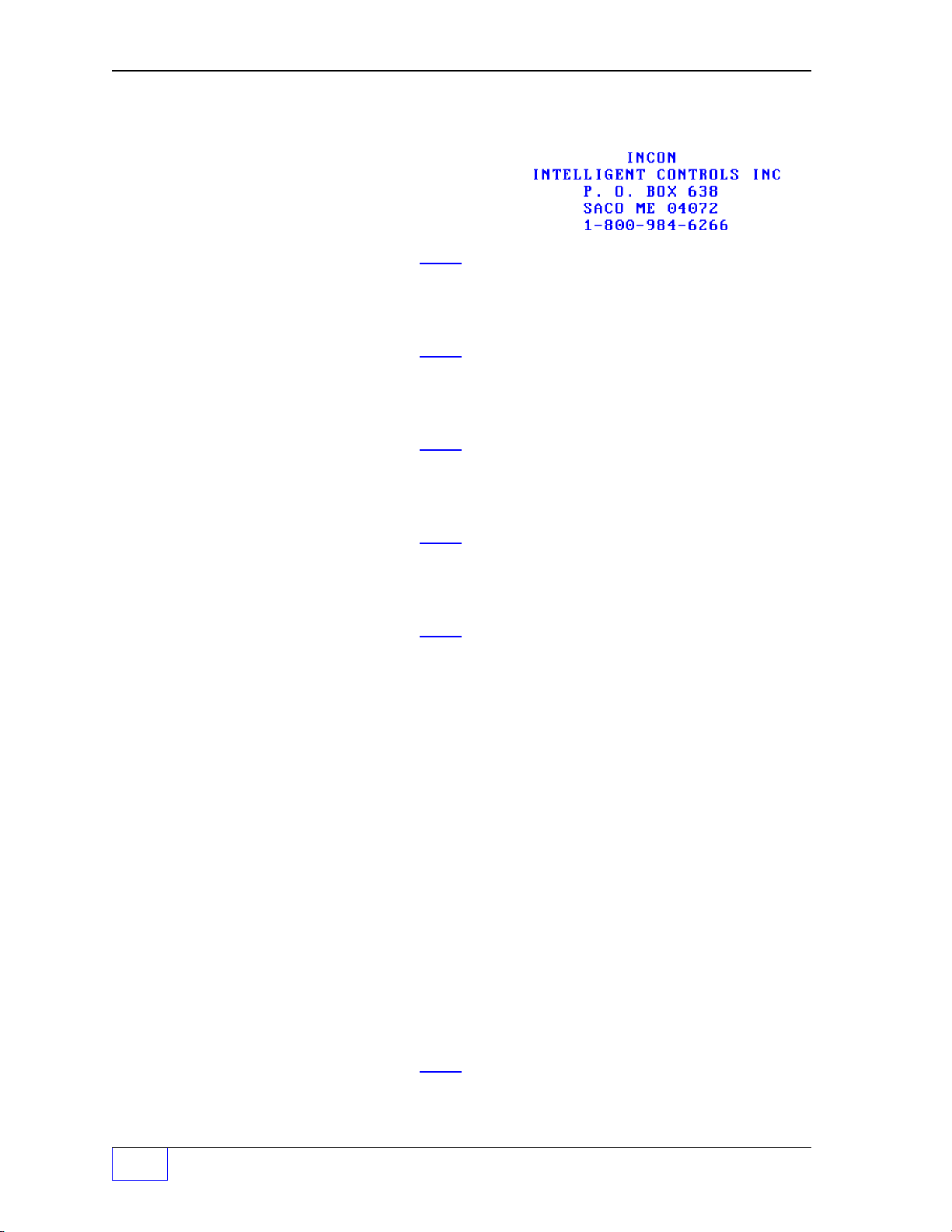
S
YSTEM
Menu (C
ONTINUED
...
FROM PREVIOUS PAGE
)
SYSTEM ID
LINE 1
LINE 2
LINE 3
LINE 4
Default Report Header Ø
LOCATION LINE 1
INCON
LOCATION LINE 2
INTELLIGENT CONTROLS
LOCATION LINE 3
P. O. BOX 638
LOCATION LINE 4
SACO ME 04072
(enter new 5 line report header, see below)
enter up to 24 characters max.
Press
ENTER
to accept this data.
enter up to 24 characters max.
Press
ENTER
to accept this data.
enter up to 24 characters max.
Press
ENTER
to accept this data.
enter up to 24 characters max.
Press
ENTER
to accept this data.
............... LINE 1
:
:
:
..... LINE 5
LINE 5
LOCATION LINE 5
1-800-984-6266
UNITS
MEASUREMENT UNITS
VOLUME
VOLUME UNITS
GALLONS
LITERS
LEVEL
LEVEL UNITS
INCHES
CM
TEMP
TEMPERATURE UNITS
FAHRENHEIT
CELSIUS
NO. TANKS
NUMBER OF TANKS
1
enter up to 24 characters max.
Press
ENTER
to accept this data.
(Units are set in either US Standard or Metric)
(– change if not using the default US units)
(volume measurement units)
Use
UP/DOWN
Press
ENTER
▲ ▼ keys to choose units.
to accept this data.
(– change if not using the default US units)
(level and length units)
Use
UP/DOWN
▲ ▼ keys to choose.
(Metric - Centimeters)
Press
ENTER
to accept this data.
(– change if not using the default US units)
(Prints F for Fahrenheit, or C for Celsius on reports)
Use
UP/DOWN
Press
ENTER
▲ ▼ keys to choose units.
to accept this data.
(enter total number of tanks in the system)
enter number of tanks.
Press
ENTER
to accept this data.
1
Page 1 - 2 Tank Sentinel Setup Programming Guide
Page 19

YSTEM
S
Menu (C
ONTINUED
...
FROM PREVIOUS PAGE
)
NO. SENSORS
NUMBER OF SENSORS
12 (for TS-1001, 504)
24 (for TS-2001, 508)
NO. METERS
NUMBER OF METERS
0
BUSY ENA
BUSY ENABLED
NO
YES
U THRESH
USER THRESHOLD
+0
LIMITS
LIMITS
LEAK LIM
LEAK LIMIT
+2.0
(enter the number of Leak Detection Sensors)
(0 thru N) enter the total number of Sensors.
(also enter all unused channels between the lowest to
highest channel (also see SENSORS menu)
Press
ENTER
to accept this data.
(devices used with TS-DIM)
enter number of meters.
Press
ENTER
to accept this data.
(dispenser supports ‘busy’ signal to ATG)
Use
UP/DOWN
Press
ENTER
▲ ▼ keys to choose setting.
to accept this data.
(volume allowed pumped before Catastrophic Leak alarm)
1 to +9999 volume units.
Press
ENTER
to accept this data.
(set leak limits for after hours sentinel mode – also see
menu)
0.2 to +10.0 volume units.
Use keypad to input sentinel mode leak rate.
Press
ENTER
to accept this data.
LEAK OG
LEAK LIMIT OUTPUT GROUP
NONE
GROUP A
thru
FF
ALL GROUPS
THEFT LIM
THEFT LIMIT
+10.0
THEFT OG
THEFT LIMIT OUTPUT GROUP
NONE
GROUP A
ALL
thru
FF
GROUPS All OGs selected
(assign leak alarm to an OG (
NONE
, A to FF, or ALL)
(32 OGs available... see Worksheet #1-1 )
Not assigned to an Output Group (OG)
One OG selected ( A = 1ST OG, FF = 32
ND OG )
All OGs selected
Use
UP/DOWN
Press
ENTER
▲ ▼ keys to choose an OG.
to accept this data.
(enter theft limit for all tanks)
1 to +9999 volume units.
Press
ENTER
(assign theft limit alarm to an OG (
to accept this data.
NONE
, A to FF, or ALL
Output Groups)(32 OGs available... see Worksheet #1-1 )
Not assigned to an Output Group (OG)
One OG selected ( A = 1ST OG, FF = 32
Use
UP/DOWN
Press
ENTER
▲ ▼ keys to choose an OG.
to accept this data.
ND OG )
System Setup Page 1 - 3
1
Page 20

S
Input time in 24 hour format:
00.00.00 = midnight
22.00.00 = 10:00:00 pm
+ 12
(add 12 hours to pm times
from 1 pm to 11:59 pm
)
02.05.00 = 2:05:00 am
YSTEM
Menu (C
ONTINUED
...
FROM PREVIOUS PA G E
)
SENTINEL
SENTINEL MODE
MODE
SENTINEL MODE
OFF
SCHEDULED
START TIM
SENTINEL START TIME
00.00.00
END TIME
SENTINEL END TIME
00.00.00
DEL DELAY
DELIVERY DELAY
15
REP DELIV
REPORT DELIVERIES
ENABLED
DISABLED
(after hours theft monitoring / tank leak detection)
Use
UP/DOWN
Press
ENTER
Select SCHEDULED to enable Sentinel Mode —
up to 23.59.59
up to 23.59.59
(delay tank delivery reports by minutes)
(minutes) 1 to 240 minute input range.
Press
ENTER
Use
UP/DOWN
Press
ENTER
(enabled = yes, report deliveries)
(disabled = no, don’t report deliveries)
▲ ▼ keys to choose mode.
to accept this data.
to accept this data.
▲ ▼ keys to choose.
to accept this data.
REP ALARM
REPORT ALARMS
ENABLED
DISABLED
REP LEAK
REPORT LEAK TESTS
ENABLED
DISABLED
REP SCALD
REPORT SCALD TEST
DISABLED
ENABLED
1
Page 1 - 4 Tank Sentinel Setup Programming Guide
Use
UP/DOWN
Press
ENTER
(enabled = yes, report alarms)
disabled = no, don’t report alarms)
Use
UP/DOWN
Press
ENTER
(enabled = yes, report leak test results)
(disabled = no don’t report leak test results)
(Appears only if an S is present in the TS Part
Number (press CHECK and M4 to view OPTIONS)
Use
UP/DOWN
Press
ENTER
(disabled = no, don’t report SCALD leak tests)
(enabled = yes, report SCALD leak tests)
▲ ▼ keys to choose.
to accept this data.
▲ ▼ keys to choose.
to accept this data.
▲ ▼ keys to choose.
to accept this data.
Page 21

S
YSTEM
Menu (C
ONTINUED
...
FROM PREVIOUS PA G E
)
REP LINES
REPORT LINE TESTS
ENABLED
DISABLED
HIST SIZE
HISTORY REPORT LENGTH
50
SYSFL OG
SYSTEM FAIL OUTPUT GROUP
NONE
GROUP A
ALL
PRNT INTR
STRAPPING TABLE PRINT INTERVAL
+1.000
thru
FF
GROUPS All OGs selected
(Appears only if an L is present in the TS Part
Number (press CHECK and M4 to view OPTIONS)
Use
UP/DOWN
Press
ENTER
(enabled = yes, report LINE leak tests)
(disabled = no, don’t report LINE leak tests)
(Max. number of alarms in Alarm History Reports)
enter range from 1 to 50 alarms shown.
Press
ENTER
(assign system fail warnings to Output Group)
(32 OGs available... see Worksheet #1)
Not assigned to an Output Group (OG)
One OG selected ( A = 1ST OG, FF = 32
Use
UP/DOWN
Press
ENTER
(how many intervals to print)
enter strapping table print interval,
range = 1 to 100.0 level units.
Press
ENTER
▲ ▼ keys to choose.
to accept this data.
to accept this data.
ND OG )
▲ ▼ keys to choose an OG.
to accept this data.
to accept this data.
DATA INTR
DATA CAPTURE INTERVAL
1
DATA TANK
TANK TO DATA LOG
1
COLD BOOT (Will erase all program data / setup data to the
IF YOU CONTINUE, ALL SYSTEM
PROGRAMMING AND DATA WILL BE LOST...
PRESS ENTER IF YOU ARE SURE THAT
YOU WANT TO CONTINUE WITH COLD BOOT
ERASING SYSTEM MEMORY ...
SYSTEM WILL REBOOT WHEN (The ATG SETUP programming is returned to the default
COMPLETE settings and must be reprogrammed to match the site.)
(for diagnostic use)
data logging interval, range = 1 to 9999.
Press
ENTER
(for diagnostic use)
tank(s) to data log, range = 1 to NO. of TANKS.
Press
ENTER
original “factory” default values)
Press
ENTER
to accept this data.
to accept this data.
to proceed with the ‘COLD BOOT’.
System Setup Page 1 - 5
1
Page 22

Worksheet #1-1 – Output Groups – System Limits
Fill-in the work sheet below and compare assignments to uncover conflicts before
programming output devices.
OG = Output Group
System Limits:
LEAK OG
THEFT OG
SYSFL OG
Example:
LEAK OG
THEFT OG
SYSFL OG
Output Devices: Modulated Annunciator, Solid Annunciator, Relay 1, Relay 2, I/O Output Module
Channel # 1 to # __ (record all OG Assignments in the vertical column)
- Output Group Assignment WORKSHEET Output Group choices -
Activates Modulated Annunciator & Relay 2 (turns on external tank leak light)
D
---
Sentinel Mode Theft Limit:
System Fail (software or hardware failures) Activate solid annunciator horn
A
none
assigned
NONE
A
B
C
D
E
F
G
H
I
J
K
L
M
N
O
P
Q
R
S
T
U
V
W
X
Y
Z
AA
BB
CC
DD
EE
FF
ALL
1
Page 1 - 6 Tank Sentinel Setup Programming Guide
Page 23

— Your Notes —
—
System Setup Page 1 - 7
❖
—
1
Page 24

2 Tanks SETUP PROGRAMMING
SELECT MENU OPTION
SETUP
UPGRADE LANGUAGE DATALOG
SETUP MENU (MORE)
EXIT SYSTEM
TANKS
PROBES
TANKS
DATA ALARMS SPECIAL
Contents:
Tank Data Menu
Tank Alarm Menu
Special Tank Menu
Worksheet 2-1, 2-2
Tank Output Groups
Tanks Menu
H U
MENU
7
× Press this key and follow the
highlighted sequence below
M1 M2 M3 M4
NOTE
☞
See the Table of Contents to find topics
in this manual. See the Preface for
general information about this manual.
See the Installation, Operator’s,
TroubleShooting Guides and Application
Notes for other reference sources.
Only the NO. (of) TANKS set under the
system menu are shown here !
Remember:
• Use
▲UP
or
DOWN
▼ keys to display more
menus (MORE shown) or selections (UP /
DN are shown)
• Press
• Use the
CANCEL
ENTER
to cancel data entry
key to accept data
Character input / editing:
M1
to
• Press menu keys
(
M4
)
to access
menus.
M1 M2 M3 M4
• Press
• Use
• Press
M1 M2 M3 M4
TANK DATA N refers to / represents a tank number
TANK 1
TANK DATA N Tank 1 is shown selected (press
COPY
COPY FROM TANK DATA X TO N
COPY FROM TANK DATA N TO N
PRESS ENTER IF YOU ARE SURE? Press
TANK 2 ...... Select the tank number to program Data.
TANK 1 Select a tank to copy data from (use
ENTER
M4
to backspace (delete) one or more
characters to the left
M2
to move the cursor right
M1
to move the cursor left
to accept this data.
ï
M1
key).
M
key).
ð
ï
Use
UP/DOWN
Tank Setup Page 2 - 1
▲▼ keys to display tanks 5-8.
2
Page 25

Tanks – TANK DATA N Menu (C
NAME (Use SHIFT to change from A-M to N-Z to NUMERIC.)
TANK NAME N
TANK N
MANIFOLD
MANIFOLD FOR TANK N (selct only when tanks are part of a manifold)
NONE
MANIFOLD 1
MANIFOLD 2 Press
:
MANIFOLD 4
SHAPE (distinguishes between underground and aboveground)
TANK SHAPE 1
HORIZONTAL
VERTICAL Press
(aboveground storage tank)
TYPE (select STANDARD 1 thru XX... see Appendix A)
TANK TYPE N
SPECIAL #
ONTINUED
N refers to / represents a tank number
Press
(INCON recommends leaving the tank name as TANK N )
Use
UP/DOWN
Use
UP/DOWN
Use
UP/DOWN
Press
(for Standard Tank types, or SPECIAL 1 thru 8 or program
the special tank(s) under the SPECIAL TANK N menu )
...
FROM PREVIOUS PA G E
enter up to 7 characters max.
ENTER
ENTER
ENTER
ENTER
to accept this data.
▲ ▼ keys to display Manifold 1 thru 4.
to accept this data.
▲ ▼ keys to choose shape.
to accept this data.
▲ ▼ keys to choose type.
to accept this data.
)
PROBE
PROBE FOR TANK N
PROBE #
PRODUCT
PRODUCT FOR TANK N
PRODUCT #
NOTE
☞
Use
UP/DOWN
Press
ENTER
Select the correct Probe channel # for TANK N...
Any Probe # (input channel Number) can be used for any Tank.
For example, Probe 8 (the probe that is wired to probe input
channel #8) can be installed in Tank 1 ....BUT a Probe can not
be used (or programmed or assigned) to more than one
tank ! Assigning the same Probe #N to more than one Tank, will
display an alarm when exiting SETUP (to warn you that more
than one tank is referencing the same probe) ! The system will
remain in setup until this problem is fixed.
Set Probe data under the PROBE menu (Chpt. 3.)
Use
UP/DOWN
Press
ENTER
(select Product 1 thru 8 ...
present if a Manifold is selected / changed from
NONE
) ...Also see PRODUCTS menu for standard
products and Special product programming.
▲ ▼ keys to choose probe#.
to accept this data.
▲ ▼ keys to choose product#.
to accept this data.
the PRODUCT menu is not
2
Page 2 - 2 Tank Sentinel Setup Programming Guide
Page 26
Tanks – TANK DATA N Menu (C
P OFFSET (to compensate product readings from tank tilts)
PRODUCT OFFSET N
+0.00000
W OFFSET (to compensate product readings from tank tilts)
WATER OFFSET N
+0.00000
DEL THRES (the minimum volume before a delivery is reported)
DELIVERY THRESHOLD N
+200.000
ONTINUED
+20 to -20
Use keypad to input level units.
Press
ENTER
(see Installation Manual for offset values)
(Not available if Manifold or Pressure probe selected)
+20 to -20
Use keypad to input level units.
Press
ENTER
(see Installation Manual for offset values)
(Not available if Manifold or Pressure probe selected)
1.0 to 99999
Use keypad to input level units.
Press
ENTER
(
the Delivery Threshold menu is not present if a
Manifold is selected / changed from NONE
...
FROM PREVIOUS PA G E
to accept this data.
to accept this data.
to accept this data.
)
)
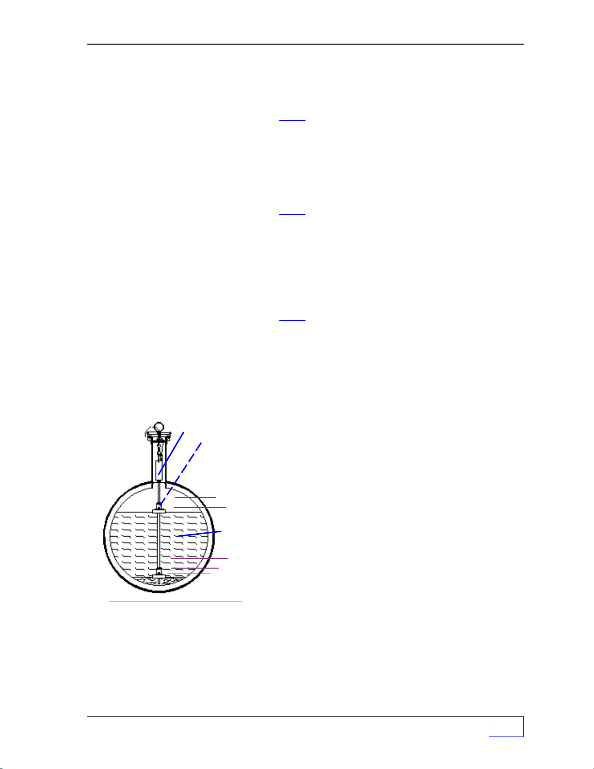
Tanks – TANK ALARM N Menu
Liquid Level Probe &
Floats
PROGRAMMED
TANK
RELATED
ALARM
LIMITS:
HIGH HIGH
HIGH
Product
LOW
LOW
LOW
HIGH
WA TER
Figure 2 - 1 Typical Tank
Limits
ALARMS (To set Tank Alarm Limits)
TANK ALARMS Use
TANK 1
TANK 2 Use
:
TANK 8
NOTES
☞
M2
Select Tank N to program, using M1 - M4 keys.
UP/DOWN
See Figure 2 - 1 at left for typical alarm limit
settings.
N refers to / represents a tank number
• The alarm copy function copies all alarm limits
from Tank X to the current Tank # N. This is a
good function to use for identical sized tanks,
and may be adequate for similar sized tanks
but limit settings may require editing after the
copy operation.
• Also note, Water, High and High High limits
are set in length units, inches or centimeters
— while Low and Low Low limits are set in
volume units,gallons or liters.
key.
▲ ▼ keys to display Tanks 5-8.
Tank Setup Page 2 - 3
2
Page 27

Tanks – TANK DATA N Menu (C
ONTINUED
...
FROM PREVIOUS PA G E
)
TANK ALARM N To select Tank N ...
COPY (COPY is optional) Press the
M1
key.
COPY FROM TANK ALARMS X TO N
TANK 1 Select a tank to copy data from (use
: Use
UP/DOWN
▲▼ keys to display tanks 5-8.
M
TANK 8 (The alarm copy function copies all alarm limits
COPY TANK ALARMS X TO N from Tank X to the current Tank # N)
PRESS ENTER IF YOU ARE SURE? Press
ENTER
to accept this data.
HIGH LIM
HIGH PRODUCT LEVEL LIMIT N
+96.0000
0.0 to 9999.0
Use keypad to input limit in inches or centimeters.
Press
ENTER
to accept this data.
H LIM OG (assign Alarm Limits to Output Group)
HIGH PRODUCT OUTPUT GROUP N (32 OGs available... see Worksheet #2 or #3)
NONE
GROUP A-FF One OG selected (
Not assigned to an output Group (OG)
A = 1ST OG, FF = 32
ALL GROUPS All OGs selected
Use
UP/DOWN
Press
ENTER
▲ ▼ keys to choose an OG.
to accept this data.
key).
ND OG )
HIGH HIGH N N refers to / represents a tank number
HI HI PRODUCT LEVEL LIMIT N
+96.0000
0.0 to 9999. (enter alarm limit)
Press
ENTER
to accept this data.
HH LIM OG N (assign Alarm Limits to Output Group)
HI HI PRODUCT OUTPUT GROUP N (32 OGs available... see Worksheet #2 or #3)
NONE
GROUP A-FF One OG selected (
Not assigned to an output Group (OG)
A = 1ST OG, FF = 32
ND OG )
ALL GROUPS All OGs selected
Use
UP/DOWN
Press
ENTER
▲ ▼ keys to choose an OG.
to accept this data.
LOW LIM N N refers to / represents a tank number
LOW PRODUCT VOLUME LIMIT N
+0.0000
0.0 to 50000 (enter alarm limit)
Press
ENTER
to accept this data.
L LIM OG N (assign Alarm Limits to Output Group)
LOW PRODUCT OUTPUT GROUP N (32 OGs available... see Worksheet #2 or #3)
NONE
GROUP A-FF One OG selected (
(A to FF, or ALL) Not assigned to an output Group (OG)
A = 1ST OG, FF = 32
ND OG )
ALL GROUPS All OGs selected
Use
UP/DOWN
Press
ENTER
▲ ▼ keys to choose an OG.
to accept this data.
LOW LOW N
LOW LOW PRODUCT VOLUME LIMIT N
+0.0000
2
Page 2 - 4 Tank Sentinel Setup Programming Guide
+ 0 to 50000 (enter alarm limit)
Press
ENTER
to accept this data.
Page 28

Tanks – TANK ALARM N Menu (C
LL LIM OG N (assign Alarm Limits to Output Group)
L L PRODUCT OUTPUT GROUP N (32 OGs available... see Worksheet #2 or #3)
NONE
GROUP A-FF One OG selected (
ALL GROUPS All OGs selected
WATER LIM N
HIGH WATER LEVEL LIMIT N
+4.0000
W LIM OG N (assign Alarm Limits to Output Group)
HIGH WATER OUTPUT GROUP N (32 OGs available... see Worksheet #2 or #3)
NONE
GROUP A-FF One OG selected (
ALL GROUPS All OGs selected
ONTINUED
Not assigned to an output Group (OG)
Use
UP/DOWN
Press
ENTER
0.0 to 9999.0 (enter alarm limit)
Press
ENTER
Not assigned to an output Group (OG)
Use
UP/DOWN
Press
ENTER
...
FROM PREVIOUS PA G E
A = 1ST OG, FF = 32
▲ ▼ keys to choose an OG.
to accept this data.
to accept this data.
A = 1ST OG, FF = 32
▲ ▼ keys to choose an OG.
to accept this data.
)
ND OG )
ND OG )
NOTE
WATER LIM N and W LIM OG N are not available for PRESSURE probes, since they do
not measure water level.
☞
Tanks – SPECIAL TANK N Menu
NOTE
☞
• If
STANDARD tanks
• Correction Tables:
then you must program a correction table (100 correction points can be programmed).
Two values are required per point / position (POS #). These are level and volume, which
are found in the manufacturers’ tank table /chart, input these accurately. Always input 0
level and 0 volume for the first point, and max. level and max. volume for the last point.
The number of points in between determines the accuracy of the strapping table.
• Cylindrical T anks:
set the length to the internal length of the tank (correction tables are usually not needed
with cylindrical tanks).
• V ertical or Rectangular tanks:
depth, and set its
max. level and max. volume for the last point.
• Correction Points
level is closest to the bottom of the tank.
length
are selcted, then these menu options will not be available.
If the Special Tank is not a perfect cylinder or has a domed end,
Select diameter and input the internal tank diameter value, and
Select diameter and input the internal tank diameter or
to zero
are automatically sorted from lowest to highest level. The lowest
( 0 )
. Input 0 level and 0 volume for the first point, and
SPECIAL
SPECIAL TANKS
SPECIAL 1
SPECIAL 2
: Use
SPECIAL 8
UP/DOWN
Tank Setup Page 2 - 5
▲▼ keys to display tanks 5-8.
2
Page 29

Tanks – SPECIAL TANK N Menu (C
SPECIAL TANK N N refers to / represents a tank number
COPY Press the
COPY FROM SPECIAL TANK X TO N Select a tank to copy data from (use
SPECIAL 1
COPY SPECIAL TANK N TO N
PRESS ENTER IF YOU ARE SURE? Press
Use
ONTINUED
M1
key.
ENTER
UP/DOWN
to accept this data.
)
M
key).
▲▼ keys to display tanks 5-8.
DIAMETER Press the
TANK DIAMETER N
+96.00
LENGTH Press the
TANK LENGTH N
+324.000
NOTE
(HEIGHT will replace LENGTH when VERTICAL is selected as the TANK DATA SHAPE)
0.0 to 999,999
Use the
Use the Keypad to input the special tank diameter.
Press
ENTER
0.0 to 999,999
Use the
Use the Keypad to input the special tank diameter.
Press
ENTER
can be added between inaccurate level positions.)
☞
HEIGHT Press the
TANK HEIGHT N
+324.000
0.0 to 1999.0
Use the
Use the Keypad to input the special tank diameter.
ENTER
Press
M2
key.
M4
key to use BACKSPACE.
to accept this data.
M3
key.
M4
key to use BACKSPACE.
to accept this data. (Correction points
M3
key.
M4
key to use BACKSPACE.
to accept this data.
CORR TABL Press the M4 key.
CORRECTION TABLE N (Position (POS #) ...see
ADD Press the
Two values (LEVEL and VOLUME) are required.
LEVEL
VOLUME
2
Page 2 - 6 Tank Sentinel Setup Programming Guide
+0
Press
+0
Press
M1
key. POS 1 is the lowest value tank.
Use the Keypad to input level of strapping point.
ENTER
Use the Keypad to input volume at that level point.
ENTER
to accept this data.
to accept this data.
NOTES
in this section)
Page 30

Tanks – SPECIAL TANK N Menu (C
DELETE
SELECT POSITION WITH UP/DN POS # Select the POS # to delete (
LEVEL
+X
VOLUME
+Y
ONTINUED
Press
ENTER
)
to accept this data.
UP/DOWN
▲▼).
ARE YOU SURE? Press
EDIT
SELECT POSITION WITH UP/DN POS # Select POS # to edit
LEVEL
DISPLAY
CORRECTION TABLE N POS N
LEVEL
+X
+X
VOLUME
VOLUME
+Y
+Y
ENTER
Press
ENTER
(correct the mistake and press
Use
UP/DOWN
to accept this data.
to accept this data.
(UP/DOWN
▲▼ keys to scroll thru list.
▲▼).
ENTER
again)
Worksheet 2-1 and 2-2 are shown on the next two pages
Tank Setup Page 2 - 7
2
Page 31

Worksheet #2-1 – Output Groups – Tanks 1 thru 4
ge,
,
)
)
)
Fill-in the work sheet below and compare assignments with other work-sheets to
uncover conflicts before programming output devices (for ALL ATG types).
OG = Output Group
Tank 1
H LIM OG
HH LIM OG
L LIM OG
LL LIM OG
W LIM OG
Tank 2
H LIM OG
HH LIM OG
L LIM OG
LL LIM OG
W LIM OG
Tank 3
H LIM OG
HH LIM OG
L LIM OG
LL LIM OG
W LIM OG
Tank 4
H LIM OG
HH LIM OG
L LIM OG
LL LIM OG
W LIM OG
- Output Group Assignment WORKSHEET Output Group choices -
Example: Tank #1
(High Limit Activates Relay 1 [for programmed timeout] to external Tank Overfill
H LIM OG
HH LIM OG
L LIM OG
LL Limit OG
W LIM OG
SYSFL OG
C
Alarm Acknowled
(High High Limit Activates Relay 2 [for programmed timeout] to activate external
D
Tank Overfill Alarm
(Low Limit Activates Output Module 2, turns on Reorder Product Light &
R
Modulated Annunciator
(Low Low Limit Activates TS-ROM Relay 1 to Disable Tank 5 STPump, and
S
Activates Modulated Annunciator
(Low Low Limit Activates TS-ROM Relay 1 to Disable Tank 5 STPump, and
S
Activates Modulated Annunciator
A
System Fail (software or hardware failures) Activate solid annunciator horn
& Activates Solid Annunciator)
& Activates Solid Annunciator)
Output Devices: Modulated Annunciator, Solid Annunciator, Relay 1, Relay 2, I/O Output Module
Channel # 1 to # __ (record all OG Assignments in the vertical column)
NONE
A
B
C
D
E
F
G
H
I
J
K
L
M
N
O
P
Q
R
S
T
U
V
W
X
Y
Z
AA
BB
CC
DD
EE
FF
ALL
2
Page 2 - 8 Tank Sentinel Setup Programming Guide
Page 32

ge,
,
)
)
)
Worksheet #2-2 – Output Groups – Tanks 5 thru 8
Fill-in the work sheet below and compare assignments with other work-sheets to
uncover conflicts before programming output devices (for TS-2001 / 508 only).
OG = Output Group
TS-2001 only:
Tank 5
H LIM OG
HH LIM OG
L LIM OG
LL LIM OG
W LIM OG
TS-2001 only:
Tank 6
H LIM OG
HH LIM OG
L LIM OG
LL LIM OG
W LIM OG
Tank 7
TS-2001 only:
H LIM OG
HH LIM OG
L LIM OG
LL LIM OG
W LIM OG
Tank 8
TS-2001 only:
H LIM OG
HH LIM OG
L LIM OG
LL LIM OG
W LIM OG
- Ou tput Group Assignment WORKSHEET Output Group choices -
Example: Tank # 5
H LIM OG
HH LIM OG
L LIM OG
LL Limit OG
W LIM OG
(High Limit Activates Relay 1 [for programmed timeout] to external Tank Overfill
C
Alarm Acknowled
(High High Limit Activates Relay 2 [for programmed timeout] to activate external
D
Tank Overfill Alarm
(Low Limit Activates Output Module 2, turns on Reorder Product Light &
R
Modulated Annunciator
(Low Low Limit Activates TS-ROM Relay 5 to Disable Tank 5 STPump, and
W
Activates Modulated Annunciator
(Low Low Limit Activates TS-ROM Relay 5 to Disable Tank 5 STPump, and
W
Activates Modulated Annunciator
& Activates Solid Annunciator)
& Activates Solid Annunciator)
Output Devices: Modulated Annunciator, Solid Annunciator, Relay 1, Relay 2, I/O Output Module
Channel # 1 to # __ (record all OG Assignments in the vertical column)
NONE
A
B
C
D
E
F
G
H
I
J
K
L
M
N
O
P
Q
R
S
T
U
V
W
X
Y
Z
AA
BB
CC
DD
EE
FF
ALL
Tank Setup Page 2 - 9
2
Page 33

— Your Notes —
—
2
Page 2 - 10 Tank Sentinel Setup Programming Guide
❖
—
Page 34

3 Lines SETUP PROGRAMMING
SELECT MENU OPTION
SETUP
UPGRADE LANGUAGE DATALOG
SETUP MENU (MORE)
EXIT SYSTEM TANKS
LINES
LINES
DATA
LINE DATA (MORE)
LINE 1 LINE 2 LINE 3
LINE DATA N (MORE)
NAME
LINE NAME N A...M
LINE 1
BACKSPACE
Contents:
Lines Menu
Line Data Menu
Lines Menu
H U
MENU
7
× Press this key and follow the
highlighted sequence below
M1 M2 M3 M4
NOTE
☞
See the Table of Contents to find topics in
this manual. See the Preface for general
information about this manual. And see the
Installation, Operator’s, TroubleShooting
Guides, and Application Notes for other
reference material.
Only the NO. (of) LINES programmed under the
system menu are shown here !
to consoles that have a L in the part number (
This menu applies
LLDI
enabled – CHECK OPTIONS).
Disregard this menu when it’s not displayed.
The purpose of this menu is to allow renaming of
the line to help identify its location. The new line
name will appear on reports and at the local tank
gauge display.
M1 M2 M3 M4
M1 M2 M3 M4
M1 M2 M3 M4
M1 M2 M3 M4
Changing the Line Name is optional.
Use the ▲
UP
or
DOWN
▼ key to display LINE 5
through LINE 8.
Use a menu select keys to choose a line.
Remember:
• Use ▲
UP
or
DOWN
▼ key to display more
menus or selections (when MORE or
UP/DN is shown)
• Press
• Use the
CANCEL
to cancel a data entry
ENTER
key to accept data
Character input / editing:
• Press
• Use
• Press
M4
to backspace (delete) one
character to the left
M2
to move the cursor right
M1
to move the cursor left
ï
ð
ï
M1 M2 M3 M4
Lines Setup Page 3 - 1
3
Page 35

Line Data Menu
LINE DATA Select a line.
LINE 1
LINE 2
: Use
LINE 8
LINE DATA N
NAME
LINE NAME N LINE N is shown typical for any line #
LINE N
UP/DOWN
Use keypad to input / edit name (9 characters max.).
Press
ENTER
▲ ▼ keys to display Lines 5 – 8.
— Your Notes —
to accept this data.
—
3
Page 3 - 2 Tank Sentinel Setup Programming Guide
❖
—
Page 36

4 Probes SETUP PROGRAMMING
SELECT MENU OPTION
SETUP
UPGRADE LANGUAGE DATALOG
SETUP MENU (MORE)
EXIT SYSTEM TANKS
PROBES
PROBES
DATA SPECIAL
Contents:
Probes Menu
Probe Data Menu
Special Probes Menu
TABLE 4.1 Special Probe RTD
Positions
Probes Menu
H U
MENU
7
× Press this key and follow the
highlighted sequence below
M1 M2 M3 M4
NOTE
☞
See the Table of Contents to find topics in
this manual. See the Preface for general
information about this manual. And see the
Installation, Operator’s, TroubleShooting
Guides, and Application Notes for other
reference material.
See the Installation Guide – Chapters 6 & 7 for
Probe Model & Serial numbers, Gradient values,
Float types, and RTD Locations).
Only the NO. (of) TANKS programmed under
the system menu are shown here !
Remember:
• Use ▲
UP
or
DOWN
▼ key to display more
menus or selections (MORE or UP/DN
shown)
• Press
• Use the
CANCEL
ENTER
to cancel data entry
key to accept data
M1 M2 M3 M4
• Press
character to the left
• Use
• Press
M1 M2 M3 M4
N refers to / represents any probe #
PROBE DATA Press (
Character input / editing:
PROBE
PROBE 2 Press
PROBE 8
1
: probes 5 – 8 (for TS-2001/508 only).
PROBE DATA N (Optional - used to copy probe data)
COPY Press
COPY FROM PROBE DATA X TO N Press (
PROBE 1
PROBE 2 Press
: probes 5 – 8 (for TS-2001/508 only).
PROBE 8
COPY FROM PROBE DATA X TO N
PRESS ENTER IF YOU ARE SURE? Press
M4
to backspace (delete) one
ï
M2
to move the cursor right
M1
to move the cursor left
M
) key to select probe # for setup.
UP/DOWN
M1
M
) key to select a probe # to copy.
UP/DOWN
ENTER
▲ ▼ keys to display
key.
▲ ▼ keys to display
to accept this data.
ð
ï
Probes Setup Page 4 - 1
4
Page 37

Probes – PROBE DATA Menu (C
ONTINUED
...
FROM PREVIOUS PA G E
)
PROBE DATA N PROBE # N shown typical for any probe # 1 – # 8
TYPE Press M2 key.
PROBE TYPE FOR PROBE N Press
STD 101
Press
UP/DOWN
ENTER
to accept this data.
▲ ▼ keys to choose.
STD 107
STD 113
STD #
probe is a STANDARD probe.
: (menus differ depending on choices)
STD 149
SPEC PROBE 1 Select SPEC PROBE N (special probe) if it
SPEC PROBE 2 is not a Standard TSP-LL2 model / type of
: probe listed in this menu...see SPECIAL
SPEC PROBE 8 menu.
PRESSURE Select PRESSURE (pressure probe)
STD 29 when programming TSP-LLP or TSP-LPG
: probes. See following section on Pressure
STD 89 probes.
GRADIENT (enter the GRADIENT from the probe label)
GRADIENT FOR PROBE N
+9.03000
8 to 9.90000
(See Installation Guide or Probe label for this
data. Also see Chapter 2 of this manual
for: Probe # — Tank # assignments)
Press
ENTER
to accept this data.
NO. FLOATS
NUMBER OF FLOATS FOR PROBE Use
2 FLOATS
1 FLOAT
FLT TYPE
FLOAT TYPE FOR PROBE N Use
GASOLINE
OIL
Probe Model
#
Probe
Gradient #
Product in
Tank (Float
type)
UP/DOWN
Press
ENTER
UP/DOWN
Press
ENTER
Number of
Probe Floats
(1 or 2)
▲ ▼ keys to choose a #.
to accept this data.
▲ ▼ keys to choose a type.
to accept this data.
Tank 1
Tank 2
Tank 3
Tank 4
Tank 5
Tank 6
Tank 7
Tank 8
4
Page 4 - 2 Tank Sentinel Setup Programming Guide
Page 38

Probes – PRESSURE PROBE DATA Menu
NOTE
This grayed out section is a duplicate of the STANDARD menu - use it to assist in
following the PRESSURE PROBE DATA MENU.
☞
PROBE DATA N PROBE # N shown typical for any probe # 1 – # 8.
COPY Press M1 key.
PROBE DATA N PROBE # N shown typical for any probe # 1 – # 8.
TYPE Press M2 key.
PROBE TYPE FOR PROBE N Press UP/DOWN ▲ ▼ keys to choose probe type.
PRESSURE Select PRESSURE (pressure probe).
when programming TS-ISCB or TSP-LLPT probes.
MODEL Press
PROBE MODEL FOR PROBE N Press
SCALE (TS-ISCB) Press
SCALE N
+9.03000
M3
key. (instead of GRADIENT for STANDARD)
UP/DOWN
or TSP-LLPT)
Press
probe.
Press
ENTER
M4
ENTER
to accept this data.
key. (instead of NO.FLOATS for STANDARD)
Use the keypad to enter the PSI as printed on the
to accept this data.
▲ ▼ keys to choose either (TS-ISCB
OFFSET(TSP-ISCB) Press
PROBE OFFSET N
+0
CONFIG (TSP-LLPT) Press
CONFIGURING PROBE (ATG will check the addresses for all probes)
SCALE (TSP-LLPT) Press
SCALE N
+9.03000
ENA TEMP (TSP-LLPT) Press
TEMPERATURE ENABLE N
NO
YES Press
OFFSET(TSP-LLPT) Press
PROBE OFFSET N
+0
Press
probe.
Press
Press
Press
M1
key. (instead of FLOAT TYPE for STANDARD)
Use the keypad to enter the OFFSET level.
ENTER
M4
M1
ENTER
M2
UP/DOWN
ENTER
M3
ENTER
to accept this data.
key. (instead of SCALE for ISCB)
key. (instead of OFFSET for ISCB)
Use the keypad to enter the PSI as printed on the
to accept this data.
key.
▲ ▼ keys to choose either (NO or YES)
to accept this data.
key.
Use the keypad to enter the OFFSET level.
to accept this data.
Probes Setup Page 4 - 3
4
Page 39

Probes – SPECIAL Menu
PROBES
DATA SPECIAL
The SPECIAL menu appears when at least one
SPEC PROBE N was selected from the
PROBES – DATA – TYPE menu (above).
M1 M2 M3 M4
SPECIAL
SPECIAL PROBES
SPECIAL 1 Press (
SPECIAL 2
: N = Special Probe # 1 thru # 8 and may or may not
SPECIAL 8 agree with the actual Tank number or Probe input
SPECIAL PROBE N channel number.
COPY (Optional - used to copy probe data)
COPY FROM SPECIAL PROBE X TO N Select a probe to copy data from (use
This menu shows all possible choices
only the selected SPECIAL PROBES N are
displayed.
M
) key to select a SPECIAL # probe.
M
key).
PROBE 1
PROBE 2 Press
: Press
PROBE 8
COPY FROM SPECIAL PROBE X TO N
PRESS ENTER IF YOU ARE SURE? Press
LENGTH
SENSOR LENGTH N
53
(press
Press
UP/DOWN
ENTER
ENTER
CANCEL
0 to 999 (Use keypad to enter probe length.)
ENTER
▲ ▼ keys to choose a probe #.
to accept this data.
to accept this data.
to prevent copying the POS#)
to accept this data.
BUT
RTD POS (RTD Temperature sensor positions are printed on
RTD POSITION TABLE N the probe label on the probe head)
ADD Press
RTD POSITION TABLE N
+0
Press
(input all 6 RTD positions as printed on the label.)
DELETE Press
SELECT POSITION WITH UP/DN POS X Press
+NN.NNNN or TABLE IS EMPTY
ARE YOU SURE? Press
EDIT Press
SELECT POSITION WITH UP/DN POS X Press
+NN.NNNN or TABLE IS EMPTY
DISPLAY Press
RTD POSITION TABLE N POS X Press
+NN.NNNN or TABLE IS EMPTY
Press
(press
Press
Use keypad to EDIT RTD POS#.
Press
Press
M1
key.
Use the keypad to enter each RTD number.
ENTER
M2
UP/DOWN
ENTER
ENTER
M3
UP/DOWN
ENTER
ENTER
M4
UP/DOWN
CANCEL
to accept this data.
key.
▲ ▼ keys to choose a POS #.
to Delete an RTD POS #.
to accept this data.
CANCEL
to prevent deleting the POS#)
key.
▲ ▼ keys to choose a POS #.
to reset the POS # to (+0).
to accept this data.
key.
▲ ▼ keys to scroll POS #.
to return to the menu.
4
Page 4 - 4 Tank Sentinel Setup Programming Guide
Page 40

Probes – SPECIAL Menu (C
RTD POSITION TABLE N POS 3
24.69
RTD POSITION TABLE N POS 1
6.10
RTD POSITION TABLE N POS 4
32.64
RTD POSITION TABLE N POS 2
16.63
RTD POSITION TABLE N POS 5
41.69
ONTINUED
Steps:
1.) Accurately fill-in TABLE 4.1
(ref. Install. Guide / Probe head / cable)
2.) Add RTD position accurately
3.) Repeat step 2 until all positions are added
4.) Display / check RTD table N positions
5.) Edit / Delete positions as required
6.) Repeat step 5 to confirm accuracy
TABLE 4.1 SPECIAL PROBE RTD POSITIONS
...
FROM PREVIOUS PAGE
)
RTD:
# 6
# 5
# 4
# 3
# 2
# 1
Probe 1 Probe 2 Probe 3 Probe 4 Probe 5 Probe 6 Probe 7 Probe 8
Probes Setup Page 4 - 5
4
Page 41

— Your Notes —
—
4
Page 4 - 6 Tank Sentinel Setup Programming Guide
❖
—
Page 42

5 Products SETUP PROGRAMMING
SETUP MENU (MORE)
EXIT SYSTEM TANKS PROBES
SELECT MENU OPTION
SETUP UPGRADE LANGUAGE DATALOG
SETUP MENU (MORE)
PRODUCTS
MANIFOLDS* REPORTS LK TSTS
PRODUCTS
DATA SPECIAL
Contents:
Products Menu
Product Data Menu
Special Product Menu
Products Menu
H U
×
MENU
7
M1 M2 M3 M4
Press this key and follow the
highlighted sequence below
See the Table of Contents to find topics in
this manual. See the Preface for general
information about this manual. And see the
Installation, Operator’s, TroubleShooting
Guides, and Application Notes for other
reference material.
NOTE
☞
Use this menu to specify the product
contained in each tank. See Appendix B for
API Gravity information – required for
Special Products programming.
NO. (of) TANKS set under the System menu
are shown !
Remember:
• Use
▲ UP
or
DOWN
▼ keys to display more
menus (MORE shown) or selections (UP/
DN shown)
• Press
• Use the
CANCEL
to cancel data entry
ENTER
key to accept data
Only the
Press the ▼
M1 M2 M3 M4
M1 M2 M3 M4
PRODUCT DATA Press
PRODUCT 1
PRODUCT 2
:
PRODUCT 8
PRODUCT DATA 1 (Optional - used to copy product data)
DOWN
key once ...
N refers to / represents a product number.
Press
Manifold Tanks will share a Product name,
**
which will cause a gap to appear in product #s.
COPY Press
Character input / editing:
• Press menu keys
M1
(
menus.
• Press
M4
to backspace (delete) one
character to the left
• Use
• Press
(M)
UP/DOWN
M1
key.
M2
to move the cursor right
M1
to move the cursor left
key to select a PRODUCT #.
▲ ▼ to display product in tanks 5 – 8.
to
ï
M4
)
to access
ð
ï
Products Setup Page 5 - 1
5
Page 43

Product Data Menu (C
ONTINUED
...
FROM PREVIOUS PA GE
)
COPY FROM PRODUCT DATA X TO N Press
PRODUCT 1
PRODUCT 2 Press
:
PRODUCT 8
COPY PRODUCT DATA X TO N
PRESS ENTER IF YOU ARE SURE? Press
(press
NAME (rename product if necessary) Press
PRODUCT NAME N
PROD N
(
optional
Use keypad to enter product names.
Press
TYPE Press
PRODUCT TYPE N (Select a Standard or Special product type in tank N)
UNLEADED REG
UNLEADED PLS
UNLEADED XTR (N = tank Number... 5 – 8 for TS-2001/508)
UNLEADED SUP
DIESEL
KEROSENE
#2 FUEL OIL
ETHANOL Select a special product (SPECIAL N) when the
SPECIAL 1 product in the tank does not match choices here.
: See SPECIAL PRODUCTS menu for programming.
SPECIAL 8
LEADED REG Press
Press
(M)
key to select a PRODUCT # to copy.
UP/DOWN
ENTER
CANCEL
9 characters (ie. 87 Octane/Cetane)
input a new name of the PRODUCT in Tank N)
ENTER
M3
UP/DOWN
ENTER
▲ ▼ to display product in tanks 5 – 8.
to accpept this data.
to prevent copying product data)
M2
to accept this data.
key.
▲ ▼ to choose a product type.
to accept this data.
key.
SPECIAL PRODUCTS Menu
NOTES
☞
SPECIAL PRODUCTS
SPECIAL 1 Press the (
SPECIAL 2
: (N = 1 – 8... 5 – 8 for TS-2001/508)
SPECIAL 8
SPECIAL PRODUCT N (Optional - used to copy product data)
COPY Press
COPY FROM SPECIAL PRODUCT X TO N Press (
SPECIAL 1
SPECIAL 2 Press
:5 – 8 (TS-2001/508
SPECIAL 8
5
Page 5- 2 Tank Sentinel Setup Programming Guide
UP/DOWN
Program SPECIAL PRODUCTS when this menu
appears
appears only after a SPECIAL product TYPE is
selected from the Product Data Menu).
To access this menu, go back to the parent
PRODUCTS menu, and choose SPECIAL (M2).
M
M1
key.
M
) key to select a product to copy.
(The SPECIAL PRODUCTS menu
) key to select a Special product#.
▲ ▼ to display special products
only).
*
Page 44

Special Products Menu (C
COPY SPECIAL PRODUCT X TO N
PRESS ENTER IF YOU ARE SURE? Press
ONTINUED
(press
...
FROM PREVIOUS PAGE
ENTER
CANCEL
to accept this data.
to prevent copying data)
)
TMP CTYPE (Temperature Compensation Type) Press
TEMPERATURE COMPENSATION TYPE N Press
API 6B/54B
API 6C/54C (changes API GRAV to DENSITY)
API 6A/54A Press
API GRAV Press
API GRAVITY N
+63.5000
Use keypad to enter the API gravity.
Press
DENSITY Press
DENSITY N
+63.5000
Use keypad to enter the DENSITY.
Press
API ALPHA Press
API ALPHA N
+600.000
Use keypad to enter the API alpha.
Press
NOTE
☞
M2
key.
UP/DOWN
ENTER
M3
key.
0.0 to 100.0
ENTER
M3
key.
500 to 2000
ENTER
M4
key.
270 to 930.0
ENTER
The following menu items appear only with the
optional: SCALD (Statistical Continuous Automatic Leak Detection) tank leak testing program
– WHEN – a special product type is selected,
otherwise disregard the items below.
▲ ▼ to choose a type.
to accept this data.
to accept this data.
to accept this data.
to accept this data.
VAPOR A Press
VAPOR A N
+12.1010
Use keypad to enter Vapor A
Press
VAPOR B Press
VAPOR B N
+8907.00
Use keypad to enter Vapor B
Press
MOLE WGHT Press
MOLE WEIGHT N
+130.000
Use keypad to enter mole weight
Press
Products Setup Page 5 - 3
M1
key.
5.0 to 20.0
ENTER
M1
ENTER
M3
ENTER
to accept this data.
key.
2000.0 to 15000.0
to accept this data.
key.
50.0 to 200.0
to accept this data.
in degrees Rankine
in degrees Rankine
in degrees Rankine
.
.
.
5
Page 45

— Your Notes —
—
5
Page 5- 4 Tank Sentinel Setup Programming Guide
❖
—
Page 46

6 Manifolds SETUP PROGRAMMING
SELECT MENU OPTION
SETUP UPGRADE LANGUAGE DATALOG
SETUP MENU (MORE)
EXIT SYSTEM TANKS PROBES
SETUP MENU (MORE)
PRODUCTS
MANIFOLDS
REPORTS LK TSTS
MANIFOLDS
DATA
ALARMS
Contents:
Manifolds Menu
Manifold Data Menu
Manifold Alarms Menu
Worksheet 6-1 – Manifolds
1 thru 4
Manifolds Menu
H U
MENU
7
× Press this key and follow the
highlighted sequence below
M1 M2 M3 M4
▼ Press the
DOWN
key ▼
See the Table of Contents to find topics in
this manual. See the Preface for general
information about this manual. And see the
Installation, Operator’s, TroubleShooting
Guides, and Application Notes for other
reference material.
*
NOTE
☞
This menu appears only after a MANIFOLD
has been selected from the
MANIFOLD
menu.
Manifolds are used to physically connect tanks
together and to expand the total capacity by the
sum of all tanks connected (see next page).
Tanks that are physically manifolded must:
1) have identical product (programmed here for
manifold tanks)
2) use the same manifold number ( 1, 2, 3 or 4 )
...ref. Chapter 2 (TANKS – DATA – TANK N
– MANIFOLD menu).
Manifold numbers must not be reused to connect
different (other) tanks & products.
TANK – DATA –
Example:
Tanks 1, 2 & 3 contain 87 Octane
gasoline and are physically manifold together
M1 M2 M3 M4
and each are programed to use Manifold #1.
Tanks 4 & 5 store 93 Octane gas and are
manifold together with Manifold #2.
that are physically manifold together must
use the same (logical) manifold number.
M1 M2 M3 M4
MANIFOLD DATA Press (M) key to select MAN 1-4 to
MAN 1 setup.
: (manifolds 3 & 4 available with TS-2001/508 only)
MAN 4
MANIFOLD DATA N N = manifold number (1 or 2, or 1 thru 4)
COPY (Optional - used to copy manifold data) Press
COPY FROM MANIFOLD DATA X TO N
MAN 1 Press (
:
MAN 4
COPY MANIFOLD DATA X TO N
PRESS ENTER IF YOU ARE SURE? Press
M
) key to select a manifold to copy data from.
ENTER
to accept this data.
All tanks
M1
key.
Manifolds Setup Page 6 - 1
6
Page 47

Manifolds Data Menu (C
NAME Press M2 key.
MANIFOLD NAME N
MAN N
ONTINUED
...
FROM PREVIOUS PAGE
9 characters
Use keypad to input a name for the Manifold.
Press
ENTER
to accept this data.
)
PRODUCT Press
PRODUCT FOR MANIFOLD N
PRODUCT 1 Press
:
PRODUCT 8 Press
DEL THRES Press
DELIVERY THRESHOLD N
UP/DOWN
ENTER
( If tanks are set to manifold, then the product
section of the tank menu disappears )
+200.000
Use keypad to input value in volume units...
per total capacity.
Press
ENTER
Manifolds ALARMS Menu
NOTE
ALARMS Press
MANIFOLD ALARMS MANIFOLD
MAN 1 Press the (
: (Manifold # 3 and 4 are for TS-2001/508 only)
MAN 4
COPY (Optional - used to copy alarm data) Press
COPY MANIFOLD ALARMS X TO N Press (
MAN 1
:
MAN 4
COPY MANIFOLD ALARMS X TO N
PRESS ENTER IF YOU ARE SURE? Press
Use this menu to input the Manifold Product Volume
Limits (optional). Access the ALARMS menu; go back to
the parent menu and then choose ALARMS ( press
ENTER
M3
key.
▲ ▼ to select a product #.
to accept this data.
M4
key.
1 to 99999.0
to accept this data.
M2
).
M2
key.
M
) key to select the MAN# for alarm setup.
M1
key.
M
) key to select MAN# to copy alarm data from.
to accept this data.
LOW LIM Press
LOW PRODUCT VOLUME LIMIT N
+0
Use keypad to input alarm limits.
Press
L LIM OG Press
LOW PRODUCT LIMIT OUTPUT GROUP N Press
NONE
GROUP A-FF One OG selected (A=1st OG, FF=32nd OG)
ALL GROUPS All OGs selected (see WORKSHEET #6-1)
6
Page 6 - 2 Tank Sentinel Setup Programming Guide
Not assigned to an OG
Press
M2
key.
0 to 50000.0
ENTER
M3
UP/DOWN
ENTER
to accept this data.
key. (Output Group = OG)
▲ ▼ to assign alarm to (OG) N
to accept this data.
Page 48

Manifolds ALARMS Menu (C
LOW LOW Press M4 key.
LOW LOW PRODUCT VOLUME LIMIT N
+0.0000
ONTINUED
Use keypad to input alarm limits.
Press
...
FROM PREVIOUS PAGE
+ 0 to 50000
ENTER
to accept this data.
)
LL LIM OG Press
LOW LOW PRODUCT LIMIT OUTPUT GRP Press
NONE
GROUP A-FF One OG selected (A=1st OG, FF=32nd OG)
ALL GROUPS All OGs selected (see WORKSHEET #6-1)
Not assigned to an OG
Press
W orksheet # 6 - 1 appears on the following page
M1
key.
UP/DOWN
ENTER
to accept this data.
▲ ▼ to assign alarm to (OG) N
Manifolds Setup Page 6 - 3
6
Page 49

)
)
Worksheet # 6-1 – Output Groups – Manifolds 1 thru 4
Fill-in the work sheet below and compare the assignments with other work-sheets to
uncover conflicts before programming output devices.
OG = Output Group
Manifold 1:
L LIM OG
LL LIM OG
Manifold 2
Man 3
Man 4
:
L LIM OG
LL LIM OG
TS-2001 only:
L LIM OG
LL LIM OG
TS-2001 only:
L LIM OG
LL LIM OG
- Output Group Assignment WORKSHEET Output Group choices -
Example: Man # 1
(Low Limit Activates Output Module 2, turns on Reorder Product Light &
L LIM OG
LL Limit OG
R
Modulated Annunciator
(Low Low Limit Activates TS-ROM Relay 5 to Disable Tank 5 STPump, and
W
Activates Modulated Annunciator
Output Devices: Modulated Annunciator, Solid Annunciator, Relay 1, Relay 2, I/O Output Module
Channel # 1 to # __ (record all OG Assignments in the vertical column)
NONE
A
B
C
D
E
F
G
H
I
J
K
L
M
N
O
P
Q
R
S
T
U
V
W
X
Y
Z
AA
BB
CC
DD
EE
FF
ALL
6
Page 6 - 4 Tank Sentinel Setup Programming Guide
Page 50

— Your Notes —
—
Manifolds Setup Page 6 - 5
❖
—
6
Page 51

7 Reconciliation SETUP PROGRAMMING
SETUP MENU (MORE)
EXIT SYSTEM TANKS PROBES
SELECT MENU OPTION
SETUP
UPGRADE LANGUAGE DATALOG
SETUP MENU (MORE)
PRODUCTS RECONCILE DIM REPORTS
RECONCILIATION
SCHEDULE TIME
Contents:
Reconciliation Menu
Reconciliation Menu
H U
MENU
7
× Press this key and follow the
highlighted sequence below
M1 M2 M3 M4
See the Table of Contents to find topics in
this manual. See the Preface for general
information about this manual. And see the
Installation, Operator’s, TroubleShooting
Guides, and Application Notes for other
reference material.
Reconciliation Notes
This menu only appears when two conditions
exist:
• The ATG configuration displays an ‘R’
• The number of
Meters
is greater than zero
The ‘R’ stands for ‘Reconciliation’ and is part
of the configuration when a TS-DIM unit is
interfaced with the ATG. This option is
programmed into the ATG at the factory, only
when ordered and specially purchased.
▼ Press the
M1 M2 M3 M4
M1 M2 M3 M4
RECONCILIATION
SCHEDULE Press
DOWN
key one or two times ...
— Continued on next page —
The number of Meters is setup under the
SYSTEM menu as described in Chapter 1 of
this guide.
The purpose of this menu is to setup a
schedule to tell the ATG when and at what
time to start Reconciliation.
INCON recommends the times coincide with
either the time a site closes (end of day) or at
the time each shift ends (end of shift).
M1
key.
Reconciliation Setup Page 7 - 1
7
Page 52

Reconciliation menu (Continued... FROM PREVIOUS PAGE)
RECONCILIATION SCHEDULE Use
NONE
SHIFT (set times for a three-shift working day)
DAILY (set the one time during the day to start)
(if SHIFT)
RECONCILIATION
SCHEDULE SHIFT 1 ... Press
RECONCILIATION SHIFT 1
10:00:00 (this equals 10 O’clock AM)
(24-hour format) Use keypad to input the SHIFT 1 start time.
(The Reconciliation Menu is displayed - set SHIFT 2 and SHIFT 3)
— Press the
(if DAILY)
RECONCILIATION
SCHEDULE TIME Press
RECONCILIATION TIME
10:00:00 (this equals 10 O’clock AM)
(24-hour format) Use keypad to input the start time.
CANCEL
key to display the main SETUP Menu —
UP/DOWN
(nothing scheduled)
Press
ENTER
M2
Press
ENTER
M2
Press
ENTER
▲ ▼ keys to choose SHIFT or DAILY.
to accept this data.
key.
to accept this data.
key.
to accept this data.
— The Reconciliation Menu is displayed —
— Press the
CANCEL
key to display the main SETUP Menu —
— Your Notes —
—
❖
—
7
Page 7 - 2 Tank Sentinel Setup Programming Guide
Page 53

8 Dispenser Interface Module (DIM) SETUP
DISPENSOR INTERFACE
METERS FUEL PTS DIMS
SETUP MENU (MORE)
PRODUCTS RECONCILE DIM REPORTS
SETUP MENU (MORE)
EXIT SYSTEM TANKS PROBES
SELECT MENU OPTION
SETUP
UPGRADE LANGUAGE DATALOG
PROGRAMMING
Contents:
DIM Menu
DIM Notes
DIM Menu
H U
MENU
7
× Press this key and follow the
highlighted sequence below
M1 M2 M3 M4
See the Table of Contents to find topics in
this manual. See the Preface for general
information about this manual. And see the
Installation, Operator’s, TroubleShooting
Guides, and Application Notes for other
reference material.
DIM Notes
Reference the TS-DIM Quick Installation
Guide (pn: 000-1058); especially use section
6 to assist in generating the data to input into
this SETUP menu.
The purpose of this menu is to program the
ATG to translate sales information from the
TS-DIM unit. This is used to automate the
task of Reconciliation.
M1 M2 M3 M4
▼ Press the
M1 M2 M3 M4
M1 M2 M3 M4
METERS
METER 1 Press
METER N
DOWN
FUEL PT Press
key one or two times ...
In order to generate the input data, run the
Win Tester Program from a laptop computer
and collect the site data. Use the results as
displayed as settings for this menu.
M1
key.
M1
key.
— Continued on next page —
DIM Setup Page 8 - 1
8
Page 54

DIM menu (Continued... FROM PREVIOUS PAGE)
FUEL PT ASSOCIATION N
1
1 - 16
Enter the fuel point number.
Use keypad to input an Association number.
Press
ENTER
to accept this data.
GRADE NO. Press
GRADE NUMBER - METER N
1
TANK A Press
TANK A ASSOCIATION N
1
TANK B Press
TANK A ASSOCIATION N
0
BLEND Press
BLENDING RATIO N
100
M2
key.
1 - 8
(reference the Win Tester Program display)
Use keypad to input an Association number.
Press
ENTER
M3
Enter the tank number that contains the product
that is being sold through this meter.
Use keypad to input an Association number.
Press
ENTER
M4
1 - 8
(only used if this meter is selling a ‘Blended’ product)
Use keypad to input an Association number.
Press
ENTER
M1
0 - 100
(Input the percentage (%) of product from Tank A used in
the ‘Blended’ product)
Use keypad to input an Association number.
Press
ENTER
to accept this data.
key.
to accept this data.
key.
to accept this data.
key.
to accept this data.
— Press the CANCEL key to display the METERS Menu —
— Repeat the above setup steps for all Meter Numbers —
— Press the CANCEL key to display the DISPENSER INTERFACE Menu —
8
Page 8 - 2 Tank Sentinel Setup Programming Guide
Page 55

DIM menu (Continued... FROM PREVIOUS PAGE)
(In most applications using one TS-DIM unit, keep these default settings)
FUEL PTS Press
FUELING POINTS
FUEL P N Press
FUELING PT N
DIM UNIT Press
DIM UNIT NUMBER - FUEL PT N
1
Press
M2
key.
M1
key.
M1
key.
Enter the TS-DIM unit number connected to this
fueling point.
Use keypad to input a number.
ENTER
to accept this data.
DIM FL PT Press
DIM FUELING POINT - FUEL PT N
1
Press
M2
key.
1 - 16
Use keypad to input a number.
ENTER
to accept this data.
— Press the CANCEL key to display the FUELING POINTS Menu —
— Repeat the above setup steps for each FUELING POINT —
— Press the CANCEL key to display the DISPENSER INTERFACE Menu —
DIMS Press M3 key.
DIMS
DIM N Press
DIM N
ADDRESS Press
DIM ADDRESS - DIM N
1
M1
key.
M1
key.
1 - 8 Enter the same number as the jumper
location found inside the TS-DIM unit.
Use keypad to input a number.
Press
ENTER
to accept this data.
— Press the CANCEL key to display the DIMS Menu —
— Repeat the above setup steps for each DIM number —
— Press the CANCEL key 2 times to display the main SETUP Menu —
DIM Setup Page 8 - 3
8
Page 56

— Your Notes —
—
8
Page 8 - 4 Tank Sentinel Setup Programming Guide
❖
—
Page 57

9 Reports SETUP PROGRAMMING
REPORT SCHEDULE (MORE)
TANK INV TANK SUM PROD INV PROD SUM
REPORT SCHEDULE (MORE)
PROD USE USE SUMRY DEL DETAI DEL SUMRY
REPORT SCHEDULE (MORE)
DELIV HST ACT ALRM CLR ALRM ALARM HST
REPORT SCHEDULE (MORE)
SCALD* SENS STAT* VAPOR* REGULTORY
TABLE 9.2 24 Hour Time Input Format
HH:MM:SS
00:00:00 = midnight
22:00:00 = 10 pm + 12 ( hours )
( add 12 hours to pm times starting at
1 pm to 11:59 pm
)
02:05:00 = 2:05 am
TABLE 9.1 Typical Report Schedule
NONE
(no schedule)
SHIFT 1ST DAY
DAILY :
MONDAY 30TH DAY
: LAST DAY
SUNDAY (
Feb. does not have 30 days)
SELECT MENU OPTION
SETUP UPGRADE LANGUAGE DATALOG
SETUP MENU (MORE)
EXIT SYSTEM TANKS PROBES
SETUP MENU (MORE)
PRODUCTS MANIFOLDS*
REPORTS
LK TSTS
REPORT SCHEDULE (MORE)
LINE COMP* LINE DIAG LINE HIST* LINE TEST*
REPORT SCHEDULE (MORE)
RECONCILE* SALES *
Contents:
– Tank – Product – Delivery
– Alarm – SCALD – Sensor
– Regulatory – Line
– Reconcile & – Sales
Reports
Reports Menu
H U
MENU
7
M1 M2 M3 M4
× Press this key in the highlighted
sequence shown below
NOTES
☞
See the Table of Contents to find topics in
this manual. See the Preface for general
information about this manual. And see the
Installation, Operator’s, TroubleShooting
Guides, and Application Notes for other
reference material.
Use this menu to program reports to print or
FAX automatically on a schedule
(faxing
requires an optional Fax/Modem device).
See Chapters 1, 10, 11 and 12 about Tank and
Line Test Reports & Scheduling.
See TABLE 9.1 –
The SHIFT
selection allows
or 3 scheduled reports to print or Fax per day
...only one report will print if two report-times
are duplicated / identical.
2
Press the
M1 M2 M3 M4
Press the
DOWN
DOWN
▼ key to show more menus...
▼ key...
The asterisked (*) menus are hardware or
software dependent and may/may not appear.
Push
UP/DOWN
▲ ▼ keys to show more
menus or menu selections.
To access menus, press the corrsponding (M)
key below each menu name.
Reports Setup Page 9 - 1
9
Page 58

Reports Schedule Menu
Tank Inventory Detail Report:
TANK INV
TANK INVENTORY DETAIL Use
SCHEDULE
NONE
TIME 1
00.00.00
TIME 2
00.00.00
TIME 3
00.00.00
FAX
NO
PRINTER
YES
Tank Inventory Summary Report:
TANK SUM
TANK INVENTORY SUMMARY Use
SCHEDULE
NONE
TIME 1
00.00.00
TIME 2
00.00.00
TIME 3
00.00.00
FAX
NO
PRINTER
YES
to 23.59.59 (input time – see TABLE 9.2)
to 23.59.59 (input shift # 2 time... N/A if not SHIFT)
to 23.59.59 (input shift # 3 time... N/A if not SHIFT)
or YES (yes requires
or NO Press
to 23.59.59 (input time – see TABLE 9.2)
to 23.59.59 (input shift # 2 time... N/A if not SHIFT)
to 23.59.59 (input shift # 3 time... N/A if not SHIFT)
or YES (yes requires
or NO Press
UP/DOWN
(select schedule – see TABLE 9.1)
ENTER
UP/DOWN
(select schedule – see TABLE 9.1)
ENTER
▲ ▼ to show choices.
optional
to accept this data.
optional
to accept this data.
fax / modem)
▲ ▼ to show choices.
fax / modem)
Product Inventory Detail Report:
PROD INV
PRODUCT INVENTORY DETAIL Use
SCHEDULE
NONE
TIME 1
9
00.00.00
TIME 2
00.00.00
TIME 3
00.00.00
FAX
NO
PRINTER
YES
Page 9 - 2 Tank Sentinel Setup Programming Guide
to 23.59.59 (input time – see TABLE 9.2)
to 23.59.59 (input shift # 2 time... N/A if not SHIFT)
to 23.59.59 (input shift # 3 time... N/A if not SHIFT)
or YES (yes requires
or NO Press
UP/DOWN
(select schedule – see TABLE 9.1)
ENTER
▲ ▼ to show choices.
optional
to accept this data.
fax / modem)
Page 59

Reports Schedule Menu (CONTINUED... FROM PREVIOUS PAGE)
Product Inventory Summary Report:
PROD SUM
PRODUCT INVENTORY SUMMARY Use
SCHEDULE
NONE
TIME 1
00.00.00
TIME 2
00.00.00
TIME 3
00.00.00
FAX
NO
PRINTER
YES
to 23.59.59 (input time – see TABLE 9.2)
to 23.59.59 (input shift # 2 time... N/A if not SHIFT)
to 23.59.59 (input shift # 3 time... N/A if not SHIFT)
or YES (yes requires
or NO Press
Product Usage Detail Report:
PROD USE
PRODUCT USAGE DETAIL Use
SCHEDULE
NONE
TIME 1
00.00.00
TIME 2
00.00.00
TIME 3
00.00.00
FAX
NO
PRINTER
YES
to 23.59.59 (input time – see TABLE 9.2)
to 23.59.59 (input shift # 2 time... N/A if not SHIFT)
to 23.59.59 (input shift # 3 time... N/A if not SHIFT)
or YES (yes requires
or NO Press
UP/DOWN
(select schedule – see TABLE 9.1)
ENTER
UP/DOWN
(select schedule – see TABLE 9.1)
ENTER
▲ ▼ to show choices.
optional
to accept this data.
optional
to accept this data.
fax / modem)
▲ ▼ to show choices.
fax / modem)
Product Usage Summary Report:
USE SUMRY
PRODUCT USAGE SUMMARY Use
SCHEDULE
NONE
TIME 1
00.00.00
TIME 2
00.00.00
TIME 3
00.00.00
FAX
NO
PRINTER
YES
to 23.59.59 (input time – see TABLE 9.2)
to 23.59.59 (input shift # 2 time... N/A if not SHIFT)
to 23.59.59 (input shift # 3 time... N/A if not SHIFT)
or YES (yes requires
or NO Press
Reports Setup Page 9 - 3
UP/DOWN
(select schedule – see TABLE 9.1)
ENTER
▲ ▼ to show choices.
optional
to accept this data.
fax / modem)
9
Page 60

Reports Schedule Menu (CONTINUED... FROM PREVIOUS PAGE)
Delivery Detail Report:
DEL DETAI
DELIVERY DETAIL Use
SCHEDULE
NONE
TIME 1
00.00.00
TIME 2
00.00.00
TIME 3
00.00.00
FAX
NO
PRINTER
YES
to 23.59.59 (input time – see TABLE 9.2)
to 23.59.59 (input shift # 2 time... N/A if not SHIFT)
to 23.59.59 (input shift # 3 time... N/A if not SHIFT)
or YES (yes requires
or NO Press
Delivery Summary Report:
DEL SUMRY
DELIVERY SUMMARY Use
SCHEDULE
NONE
TIME 1
00.00.00
TIME 2
00.00.00
TIME 3
00.00.00
FAX
NO
PRINTER
YES
to 23.59.59 (input time – see TABLE 9.2)
to 23.59.59 (input shift # 2 time... N/A if not SHIFT)
to 23.59.59 (input shift # 3 time... N/A if not SHIFT)
or YES (yes requires
or NO Press
UP/DOWN
(select schedule – see TABLE 9.1)
ENTER
UP/DOWN
(select schedule – see TABLE 9.1)
ENTER
▲ ▼ to show choices.
optional
to accept this data.
optional
to accept this data.
fax / modem)
▲ ▼ to show choices.
fax / modem)
Delivery History Report:
DELIV HST
DELIVERY HISTORY Use
SCHEDULE
NONE
TIME 1
9
00.00.00
TIME 2
00.00.00
TIME 3
00.00.00
FAX
NO
PRINTER
YES
Page 9 - 4 Tank Sentinel Setup Programming Guide
to 23.59.59 (input time – see TABLE 9.2)
to 23.59.59 (input shift # 2 time... N/A if not SHIFT)
to 23.59.59 (input shift # 3 time... N/A if not SHIFT)
or YES (yes requires
or NO Press
UP/DOWN
(select schedule – see TABLE 9.1)
ENTER
▲ ▼ to show choices.
optional
to accept this data.
fax / modem)
Page 61

Reports Schedule Menu (CONTINUED... FROM PREVIOUS PAGE)
Active Alarm Report:
ACT ALRM
ACTIVE ALARM Use
SCHEDULE
NONE
TIME 1
00.00.00
TIME 2
00.00.00
TIME 3
00.00.00
FAX
NO
PRINTER
YES
to 23.59.59 (input time – see TABLE 9.2)
to 23.59.59 (input shift # 2 time... N/A if not SHIFT)
to 23.59.59 (input shift # 3 time... N/A if not SHIFT)
or YES (yes requires
or NO Press
Cleared Alarm Report:
CLR ALRM
CLEARED ALARM Use
SCHEDULE
NONE
TIME 1
00.00.00
TIME 2
00.00.00
TIME 3
00.00.00
FAX
NO
PRINTER
YES
to 23.59.59 (input time – see TABLE 9.2)
to 23.59.59 (input shift # 2 time... N/A if not SHIFT)
to 23.59.59 (input shift # 3 time... N/A if not SHIFT)
or YES (yes requires
or NO Press
UP/DOWN
(select schedule – see TABLE 9.1)
ENTER
UP/DOWN
(select schedule – see TABLE 9.1)
ENTER
▲ ▼ to show choices.
optional
to accept this data.
optional
to accept this data.
fax / modem)
▲ ▼ to show choices.
fax / modem)
Alarm History Report:
ALARM HST
ALARM HISTORY Use
SCHEDULE
NONE
TIME 1
00.00.00
TIME 2
00.00.00
TIME 3
00.00.00
FAX
NO
PRINTER
YES
to 23.59.59 (input time – see TABLE 9.2)
to 23.59.59 (input shift # 2 time... N/A if not SHIFT)
to 23.59.59 (input shift # 3 time... N/A if not SHIFT)
or YES (yes requires
or NO Press
Reports Setup Page 9 - 5
UP/DOWN
(select schedule – see TABLE 9.1)
ENTER
▲ ▼ to show choices.
optional
to accept this data.
fax / modem)
9
Page 62

Reports Schedule Menu (C
SCALD Leak Test: Report
ONTINUED
...
FROM PREVIOUS PA G E
)
SCALD
SCALD TEST Use
SCHEDULE
Only with SCALD Tank Leak Test program
*
NONE
TIME 1
00.00.00
TIME 2
00.00.00
TIME 3
00.00.00
FAX
NO
PRINTER
YES
to 23.59.59 (input time – see TABLE 9.2)
to 23.59.59 (input shift # 2 time... N/A if not SHIFT)
to 23.59.59 (input shift # 3 time... N/A if not SHIFT)
or YES (yes requires
or NO Press
Sensor Status Report
SENS STAT
SENSOR STATUS Use
SCHEDULE
NONE
TIME 1
00.00.00
TIME 2
00.00.00
TIME 3
00.00.00
FAX
NO
PRINTER
YES
Only if No. of Sensors > Ø
*
to 23.59.59 (input time – see TABLE 9.2)
to 23.59.59 (input shift # 2 time... N/A if not SHIFT)
to 23.59.59 (input shift # 3 time... N/A if not SHIFT)
or YES (yes requires
or NO Press
UP/DOWN
(select schedule – see TABLE 9.1)
ENTER
UP/DOWN
(select schedule – see TABLE 9.1)
ENTER
▲ ▼ to show choices.
optional
to accept this data.
optional
to accept this data.
fax / modem)
▲ ▼ to show choices.
fax / modem)
Vapor Sensor:
VAPOR
VAPOR SENSOR Use
SCHEDULE
NONE
TIME 1
00.00.00
TIME 2
00.00.00
TIME 3
00.00.00
FAX
NO
PRINTER
YES
9
Page 9 - 6 Tank Sentinel Setup Programming Guide
Only with TSP-DVS Vapor Sensor(s)
*
to 23.59.59 (input time – see TABLE 9.2)
to 23.59.59 (input shift # 2 time... N/A if not SHIFT)
to 23.59.59 (input shift # 3 time... N/A if not SHIFT)
or YES (yes requires
or NO Press
UP/DOWN
(select schedule – see TABLE 9.1)
ENTER
▲ ▼ to show choices.
optional
to accept this data.
fax / modem)
Page 63

Reports Schedule Menu (C
ONTINUED
Regulatory Report:
REGULTORY
REGULATORY Use
SCHEDULE
NONE
TIME 1
00.00.00
TIME 2
00.00.00
TIME 3
00.00.00
FAX
NO
PRINTER
YES
to 23.59.59 (input time – see TABLE 9.2)
to 23.59.59 (input shift # 2 time... N/A if not SHIFT)
to 23.59.59 (input shift # 3 time... N/A if not SHIFT)
or YES (yes requires
or NO Press
Line Compliance Report:
...
FROM PREVIOUS PA G E
UP/DOWN
(select schedule – see TABLE 9.1)
▲ ▼ to show choices.
optional
ENTER
to accept this data.
)
fax / modem)
LINE COMP
LINE COMPLIANCE Use
SCHEDULE
Only with Line Leak Detector(s)
*
NONE
TIME 1
00.00.00
TIME 2
00.00.00
TIME 3
00.00.00
FAX
NO
PRINTER
YES
to 23.59.59 (input time – see TABLE 9.2)
to 23.59.59 (input shift # 2 time... N/A if not SHIFT)
to 23.59.59 (input shift # 3 time... N/A if not SHIFT)
or YES (yes requires
or NO Press
Line Diagnostics Report:
LINE DIAG
LINE DIAGNOSTIC Use
SCHEDULE
NONE
TIME 1
00.00.00
TIME 2
00.00.00
TIME 3
00.00.00
FAX
NO
PRINTER
YES
Only with Line Leak Detector(s)
*
to 23.59.59 (input time – see TABLE 9.2)
to 23.59.59 (input shift # 2 time... N/A if not SHIFT)
to 23.59.59 (input shift # 3 time... N/A if not SHIFT)
or YES (yes requires
or NO Press
UP/DOWN
(select schedule – see TABLE 9.1)
ENTER
UP/DOWN
(select schedule – see TABLE 9.1)
ENTER
▲ ▼ to show choices.
optional
to accept this data.
optional
to accept this data.
fax / modem)
▲ ▼ to show choices.
fax / modem)
Reports Setup Page 9 - 7
9
Page 64

Reports Schedule Menu (C
Line Test History Report:
ONTINUED
...
FROM PREVIOUS PA G E
)
LINE HIST
LINE TEST HISTORY Use
SCHEDULE
Only with Line Leak Detector(s)
*
NONE
TIME 1
00.00.00
TIME 2
00.00.00
TIME 3
00.00.00
FAX
NO
PRINTER
YES
to 23.59.59 (input time – see TABLE 9.2)
to 23.59.59 (input shift # 2 time... N/A if not SHIFT)
to 23.59.59 (input shift # 3 time... N/A if not SHIFT)
or YES (yes requires
or NO Press
Line Test Report:
LINE TEST
LINE TEST Use
SCHEDULE
NONE
TIME 1
00.00.00
TIME 2
00.00.00
TIME 3
00.00.00
FAX
NO
PRINTER
YES
Only with Line Leak Detector(s)
*
to 23.59.59 (input time – see TABLE 9.2)
to 23.59.59 (input shift # 2 time... N/A if not SHIFT)
to 23.59.59 (input shift # 3 time... N/A if not SHIFT)
or YES (yes requires
or NO Press
UP/DOWN
(select schedule – see TABLE 9.1)
ENTER
UP/DOWN
(select schedule – see TABLE 9.1)
ENTER
▲ ▼ to show choices.
optional
to accept this data.
optional
to accept this data.
fax / modem)
▲ ▼ to show choices.
fax / modem)
Shift Reconciliation Report:
RECONCILE Press the (M) key below this menu item.
— Reconciliation Report Schedules (5) —
SHIFT REC
SHIFT RECONCILIATION Use
SCHEDULE
NONE
TIME 1
00.00.00
TIME 2
00.00.00
TIME 3
00.00.00
FAX
NO
PRINTER
YES
9
Page 9 - 8 Tank Sentinel Setup Programming Guide
Only with Reconciliation / DIM
*
to 23.59.59 (input time – see TABLE 9.2)
to 23.59.59 (input shift # 2 time... N/A if not SHIFT)
to 23.59.59 (input shift # 3 time... N/A if not SHIFT)
or YES (yes requires
or NO Press
UP/DOWN
(select schedule – see TABLE 9.1)
ENTER
▲ ▼ to show choices.
optional
to accept this data.
fax / modem)
Page 65

Reports Schedule Menu (C
Daily Reconciliation Report:
ONTINUED
...
FROM PREVIOUS PA G E
)
DAILY REC
DAILY RECONCILIATION Use
SCHEDULE
Only with Reconciliation / DIM
*
NONE
TIME 1
00.00.00
TIME 2
00.00.00
TIME 3
00.00.00
FAX
NO
PRINTER
YES
to 23.59.59 (input time – see TABLE 9.2)
to 23.59.59 (input shift # 2 time... N/A if not SHIFT)
to 23.59.59 (input shift # 3 time... N/A if not SHIFT)
or YES (yes requires
or NO Press
Monthly Reconciliation Report:
MONTH REC
MONTH RECONCILIATION Use
SCHEDULE
NONE
TIME 1
00.00.00
TIME 2
00.00.00
TIME 3
00.00.00
FAX
NO
PRINTER
YES
Only with Reconciliation / DIM
*
to 23.59.59 (input time – see TABLE 9.2)
to 23.59.59 (input shift # 2 time... N/A if not SHIFT)
to 23.59.59 (input shift # 3 time... N/A if not SHIFT)
or YES (yes requires
or NO Press
UP/DOWN
(select schedule – see TABLE 9.1)
ENTER
UP/DOWN
(select schedule – see TABLE 9.1)
ENTER
▲ ▼ to show choices.
optional
to accept this data.
optional
to accept this data.
fax / modem)
▲ ▼ to show choices.
fax / modem)
Shift Reconciliation History Report:
SHIFT HST
SHIFT RECONCILIATION HISTORY Use
SCHEDULE
NONE
TIME 1
00.00.00
TIME 2
00.00.00
TIME 3
00.00.00
FAX
NO
PRINTER
YES
Only with Reconciliation / DIM
*
to 23.59.59 (input time – see TABLE 9.2)
to 23.59.59 (input shift # 2 time... N/A if not SHIFT)
to 23.59.59 (input shift # 3 time... N/A if not SHIFT)
or YES (yes requires
or NO Press
Reports Setup Page 9 - 9
UP/DOWN
(select schedule – see TABLE 9.1)
ENTER
▲ ▼ to show choices.
optional
to accept this data.
fax / modem)
9
Page 66

Reports Schedule Menu (C
Daily Reconciliation History Report:
ONTINUED
...
FROM PREVIOUS PA G E
)
DAILY HST
DAILY RECONCILIATION HISTORY Use
SCHEDULE
NONE
TIME 1
00.00.00
TIME 2
00.00.00
TIME 3
00.00.00
FAX
NO
PRINTER
YES
Only with Reconciliation / DIM
*
to 23.59.59 (input time – see TABLE 9.2)
to 23.59.59 (input shift # 2 time... N/A if not SHIFT)
to 23.59.59 (input shift # 3 time... N/A if not SHIFT)
or YES (yes requires
or NO Press
UP/DOWN
(select schedule – see TABLE 9.1)
ENTER
▲ ▼ to show choices.
optional
to accept this data.
fax / modem)
Shift Sales Report:
SALES Press the (M) key below this menu item.
— Sales Report Schedules (5) —
SALES REPORT SCHEDULE
SHIFT SAL Use
SCHEDULE
NONE
TIME 1
00.00.00
TIME 2
00.00.00
TIME 3
00.00.00
FAX
NO
PRINTER
YES
Only with Reconciliation / DIM
*
to 23.59.59 (input time – see TABLE 9.2)
to 23.59.59 (input shift # 2 time... N/A if not SHIFT)
to 23.59.59 (input shift # 3 time... N/A if not SHIFT)
or YES (yes requires
or NO Press
UP/DOWN
(select schedule – see TABLE 9.1)
ENTER
▲ ▼ to show choices.
optional
to accept this data.
fax / modem)
Daily Sales Report:
SALES REPORT SCHEDULE
DAILY SAL Use
SCHEDULE
NONE
TIME 1
00.00.00
TIME 2
00.00.00
TIME 3
00.00.00
FAX
NO
PRINTER
YES
9
Page 9 - 10 Tank Sentinel Setup Programming Guide
Only with Reconciliation / DIM
*
to 23.59.59 (input time – see TABLE 9.2)
to 23.59.59 (input shift # 2 time... N/A if not SHIFT)
to 23.59.59 (input shift # 3 time... N/A if not SHIFT)
or YES (yes requires
or NO Press
UP/DOWN
(select schedule – see TABLE 9.1)
ENTER
▲ ▼ to show choices.
optional
to accept this data.
fax / modem)
Page 67

Reports Schedule Menu (C
Monthly Sales Report:
ONTINUED
...
FROM PREVIOUS PA G E
)
SALES REPORT SCHEDULE
MONTH SAL Use
SCHEDULE
Only with Reconciliation / DIM
*
NONE
TIME 1
00.00.00
TIME 2
00.00.00
TIME 3
00.00.00
FAX
NO
PRINTER
YES
to 23.59.59 (input time – see TABLE 9.2)
to 23.59.59 (input shift # 2 time... N/A if not SHIFT)
to 23.59.59 (input shift # 3 time... N/A if not SHIFT)
or YES (yes requires
or NO Press
Shift History Report:
SALES REPORT SCHEDULE
SHIFT HST Use
SCHEDULE
NONE
TIME 1
00.00.00
TIME 2
00.00.00
TIME 3
00.00.00
FAX
NO
PRINTER
YES
Only with Reconciliation / DIM
*
to 23.59.59 (input time – see TABLE 9.2)
to 23.59.59 (input shift # 2 time... N/A if not SHIFT)
to 23.59.59 (input shift # 3 time... N/A if not SHIFT)
or YES (yes requires
or NO Press
UP/DOWN
(select schedule – see TABLE 9.1)
ENTER
UP/DOWN
(select schedule – see TABLE 9.1)
ENTER
▲ ▼ to show choices.
optional
to accept this data.
optional
to accept this data.
fax / modem)
▲ ▼ to show choices.
fax / modem)
Daily History Report:
SALES REPORT SCHEDULE
DAILY HST Use
SCHEDULE
NONE
TIME 1
00.00.00
TIME 2
00.00.00
TIME 3
00.00.00
FAX
NO
PRINTER
YES
Only with Reconciliation / DIM
*
to 23.59.59 (input time – see TABLE 9.2)
to 23.59.59 (input shift # 2 time... N/A if not SHIFT)
to 23.59.59 (input shift # 3 time... N/A if not SHIFT)
or YES (yes requires
or NO Press
Reports Setup Page 9 - 11
UP/DOWN
(select schedule – see TABLE 9.1)
ENTER
▲ ▼ to show choices.
optional
to accept this data.
fax / modem)
9
Page 68

— Your Notes —
—
9
Page 9 - 12 Tank Sentinel Setup Programming Guide
❖
—
Page 69

10 Leak Test SETUP PROGRAMMING
LEAK TESTS (MORE)
ALARM ON TST FL OG*
LEAK TESTS (MORE)
CONFIDENCE PRECISION MIN LK TM SCHEDULE
SETUP MENU (MORE)
PRODUCTS MANIFOLDS* REPORTS
LK TESTS
SETUP MENU (MORE)
EXIT SYSTEM TANKS PROBES
SELECT MENU OPTION
SETUP UPGRADE LANGUAGE DATALOG
Contents:
Tank Leak Test Menu
(Standard Static Test)
Output Group Assignments
Worksheet 10-1
Leak Test Menu (Static Tank)
H U
MENU
7 highlighted sequence below
× Press this key and follow the
M1 M2 M3 M4
See the Table of Contents to find topics in
this manual. See the Preface for general
information about this manual. And see
the Installation, Operator’s,
TroubleShooting Guides, and Application
Notes for other reference material.
Only the number of tanks that were programmed
under the SYSTEM menu will be displayed here
(Ø = No tank-related menus).
Static tank leak tests require 2 to 8 hours of
uninterrupted
quiet-time
to finish with no
dispensing, deliveries or line leak tests running
during the test.
Press the
M1 M2 M3 M4
M1 M2 M3 M4
Press the
M1 M2 M3 M4
DOWN
▼ key
DOWN ▼
key
Wait at least 2 hours after a dispense or line leak
test, and 6 hours after a delivery for valid test
results. The occurrence of any of these events
will cause the test to produce failed, or
indeterminate test results.
Before programming see State and Local
Regulations about leak testing (frequency,
minimum volume / capacity, and leak test
precision) and reporting requirements... adhere
to these requirements.
* Appears only if alarm on = yes (see
following page).
Begin programming with the CONFIDENCE
menu. Follow the sequences on the next
page.
Tank Leak Test Setup Page 10 - 1
10
Page 70

Tank Leak Test Menu
N = Tanks 1 – 8
(only the number of tanks programmed in
the System menu will appear)
Setup the confidence percentage
CONFIDENC Press M1 key.
LEAK TEST CONFIDENCE
99.0(%)
90.0% Press
Use
UP/DOWN
ENTER
▲ ▼ keys to show choices.
to accept this data.
95.0%
97.5%
Setup the percision of the leak test
PRECISION Press M2 key.
LEAK TEST PRECISION Select tank number using (M) key.
TANK 1
TANK 2
:
TANK 8 (NOTE: 5 – 8 TS-2001/508 only)
LEAK TEST PRECISION
+0.20000
0.05 to 2.0
Use keypad to input a precision number.
Press
ENTER
to accept this data.
Static Leak Test:
Precision Tank # 1
Precision Tank # 2
Precision Tank # 3
Precision Tank # 4
Precision Tank # 5
Precision Tank # 6
Precision Tank # 7
Precision Tank # 8
Threshold = 1/2 of Leak Test value
Monthly
Compliance
0.2 gph 0.1 gph
Yearly Test
Setup a minimum amount of time to test for leaks per local regulations —
MIN LK TM Press M3 key.
MINIMUM LEAK TEST TIME
2
2 to 8.0 hours
Use keypad to input minimum leak test time.
Press
ENTER
to accept this data.
10
— Continued next page —
Page 10 - 2 Tank Sentinel Setup Programming Guide
Page 71

Tank Leak Test Menu (C
TABLE 10.2 24 Hour Time
Input Format
HH:MM:SS
00:00:00 = midnight
22:00:00 = 10 pm + 12 ( hours )
( add 12 hours to pm times starting at
1 pm to 11:59 pm
)
02:05:00 = 2:05 am
TABLE 10.1 TYPICAL TEST
SCHEDULE
NONE
( no schedule )
DAILY 1ST DAY
MONDAY :
: 30TH DAY
SUNDAY LAST DAY
February does not have 30 days.
ONTINUED
...
FROM PREVIOUS PAGE
Setup automatic leak test schedules for all tanks —
SCHEDULE Press the M4 key.
LEAK TEST SCHEDULE
TANK 1 Press an (
TANK 2
:
TANK 8
LEAK TEST SCHEDULE FOR TANK N
COPY (Optional - used to copy schedules) Press the
COPY FROM LEAK SCHEDULE X TO N Press an (
TANK 1
TANK 2
: for TS-2001/508 only.
TANK 8
COPY LEAK SCHEDULE X TO N
PRESS ENTER IF YOU ARE SURE? Press
Press
M
) key to select a tank to scedule.
M
) key to select a tank to copy.
UP/DOWN
ENTER
▲ ▼ to display Tanks 5 – 8
to accept this data.
)
M1
key.
SCHEDULE Press the
LEAK TEST SCHEDULE FOR TANK N
NONE
:
LAST DAY Press
Use
Start time for Tank N (can be the same for all)
TIME Press the M3 key.
00:00:00
Use keypad to input time (see TABLE 10.2).
Press
M4
key.
UP/DOWN
ENTER
24 HOUR FORMAT
ENTER
▲ ▼ to show choices (see TABLE 10.1).
to accept this data.
to accept this data.
ALARM ON Press the
ALARM ON TEST FAIL
NO
YES YES = generate an alarm if a tank leak test fails
M3
key.
Use
UP/DOWN
Press
ENTER
— Continued next page —
Tank Leak Test Setup Page 10 - 3
▲ ▼ to show choices.
to accept this data.
10
Page 72

Tank Leak Test Menu (C
(* This menu appears only when YES was selected under the ALARM ON TEST FAIL menu)
ONTINUED
...
FROM PREVIOUS PAGE
)
TST FL OG Press the
TEST FAIL OUTPUT GRP
TANK 1
: Press an (
TANK 8
LEAK TEST FAIL OUTPUT GROUP N (32 OGs available, see WORKSHEET # 10-1)
NONE
GROUP A-FF One OG selected (A=1st OG, FF=32nd OG)
ALL GROUPS All OGs selected
Not Assigned to an OG.
Use
Press
M3
key.
M
) key to select a tank to assign an OG.
UP/DOWN
ENTER
▲ ▼ to show OG choices.
to accept this data.
— Your Notes —
10
Page 10 - 4 Tank Sentinel Setup Programming Guide
Page 73

Worksheet # 10-1 – Output Groups – Tank Leak Tests
for Static & SCALD Tank Leak Tests
assignments with other worksheets to uncover conflicts before programming output
devices.
See the
Chapter
on SCALD
tank leak
testing...
Annunciators
or external
relay output
in this
example
flag the
test fail
alarm
Fill-in the worksheet below. Compare
OG = Output Group
Tank Leak Test:
TST FL OG Tank 1
TST FL OG Tank 2
TST FL OG Tank 3
TST FL OG Tank 4
TST FL OG Tank 5
TST FL OG Tank 6
TST FL OG Tank 7
TST FL OG Tank 8
SCALD Test:
TST FL OG Tank 1
TST FL OG Tank 2
TST FL OG Tank 3
TST FL OG Tank 4
TST FL OG Tank 5
TST FL OG Tank 6
TST FL OG Tank 7
TST FL OG Tank 8
Example:
Tank Leak Test:
TST FL OG 1
SCALD Test:
TST FL OG 3
Output Devices: Modulated Annunciator, Solid Annunciator, Relay 1, Relay 2, I/O Output Module
Channel # 1 to # __ (record all OG Assignments in the vertical column)
- Output Group Assignment WORKSHEET Output Group choices -
Activates Modulated Annunciator & Relay 2 (turns on external tank leak light)
G
Activates Modulated Annunciator & Relay 2 (turns on external tank leak light)
G
NONE
A
B
C
D
E
F
G
H
I
J
K
L
M
N
O
P
Q
R
S
T
U
V
W
X
Y
Z
AA
BB
CC
DD
EE
FF
ALL
— ❖ —
Tank Leak Test Setup Page 10 - 5
10
Page 74
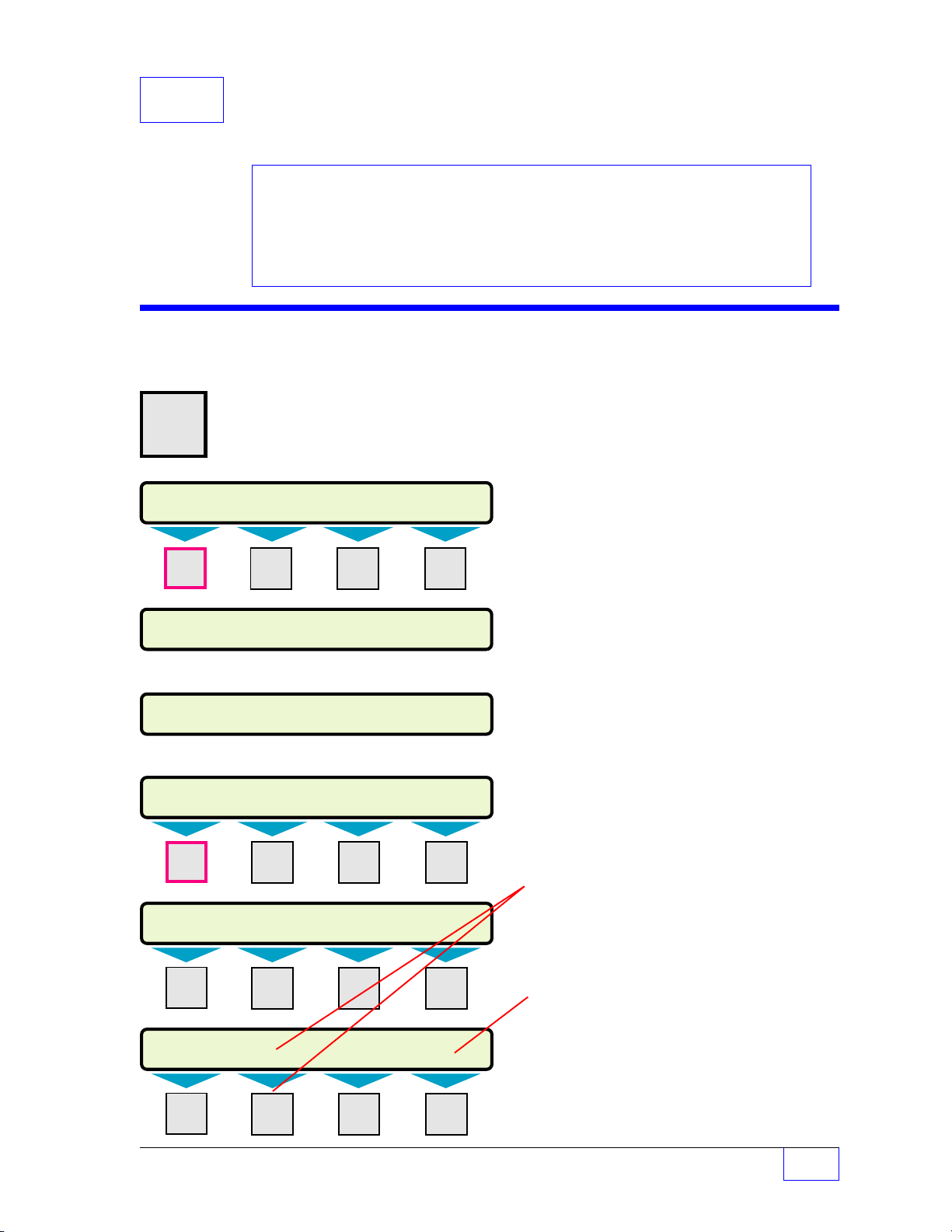
11 SCALD
SETUP MENU (MORE)
PRODUCTSMANIFOLDS* REPORTS LK TESTS
SCALD TESTS (MORE)
ENABLE VAPOR REC ALARM ON TST FL OG*
SELECT MENU OPTION
SETUP UPGRADE LANGUAGE DATALOG
SETUP MENU (MORE)
EXIT SYSTEM TANKS PROBES
SETUP MENU (MORE)
SCLD TEST
CLK/CAL ANNUNC RELAYS
SCALD TESTS (MORE)
CONFIDENCE PRECISION INTERVAL QUALIFY
SETUP PROGRAMMING
®
Tank Leak Test
Contents:
SCALD Tank Leak Test Menu
Output Group Assignments
see Worksheet 8-1
SCALD Tank Leak Test Menu
H U
MENU
7
M1 M2 M3 M4
× Press this key and follow the
highlighted sequence below
▼ Press
▼ Press
DOWN
DOWN
See the Table of Contents to find topics in
this manual. See the Preface for general
information about this manual. And see the
Installation, Operator’s, TroubleShooting
Guides, and Application Notes for other
reference material.
Disregard this Chapter if the SCLD TEST menu
does not appear (the position of this menu can
also be displaced by other menus).
SCALD
®
is an
acronym for INCON’s optional
Statistical Continuous Automatic Leak
Detection program. It runs volumetric leak tests
during the
quiet-times
between dispenses. It is
suited for 24 hour dispense sites that are too
busy to run static leak tests.
The system is pre-configured with default setup
that will give you the best results for most
situations — keep the default settings. The
exceptions to this are: ENABLE Vapor Recovery
when a Stage II Vapor Recovery is used at the
site and, when a SCALD leak test failure alarm
is needed, program ALARM ON and TST FL OG
(test fail output group) menus.
M1 M2 M3 M4
M1 M2 M3 M4
M1 M2 M3 M4
Push the
menus or menu selections.
Press menu keys
Push
value into the setup configuration memory.
TST FL OG appears only if YES has been
*
programmed for ALARM ON (see next page).
Only the number of tanks that were programmed
under the SYSTEM menu will be displayed here
(
Ø
= No tank-related menus).
SCALD Tank Leak Test Setup Page 11 - 1
UP/DOWN
ENTER
keys ▲ ▼ to show more
(M1
to
M4)
to accept a selection or input a
to access menus.
11
Page 75
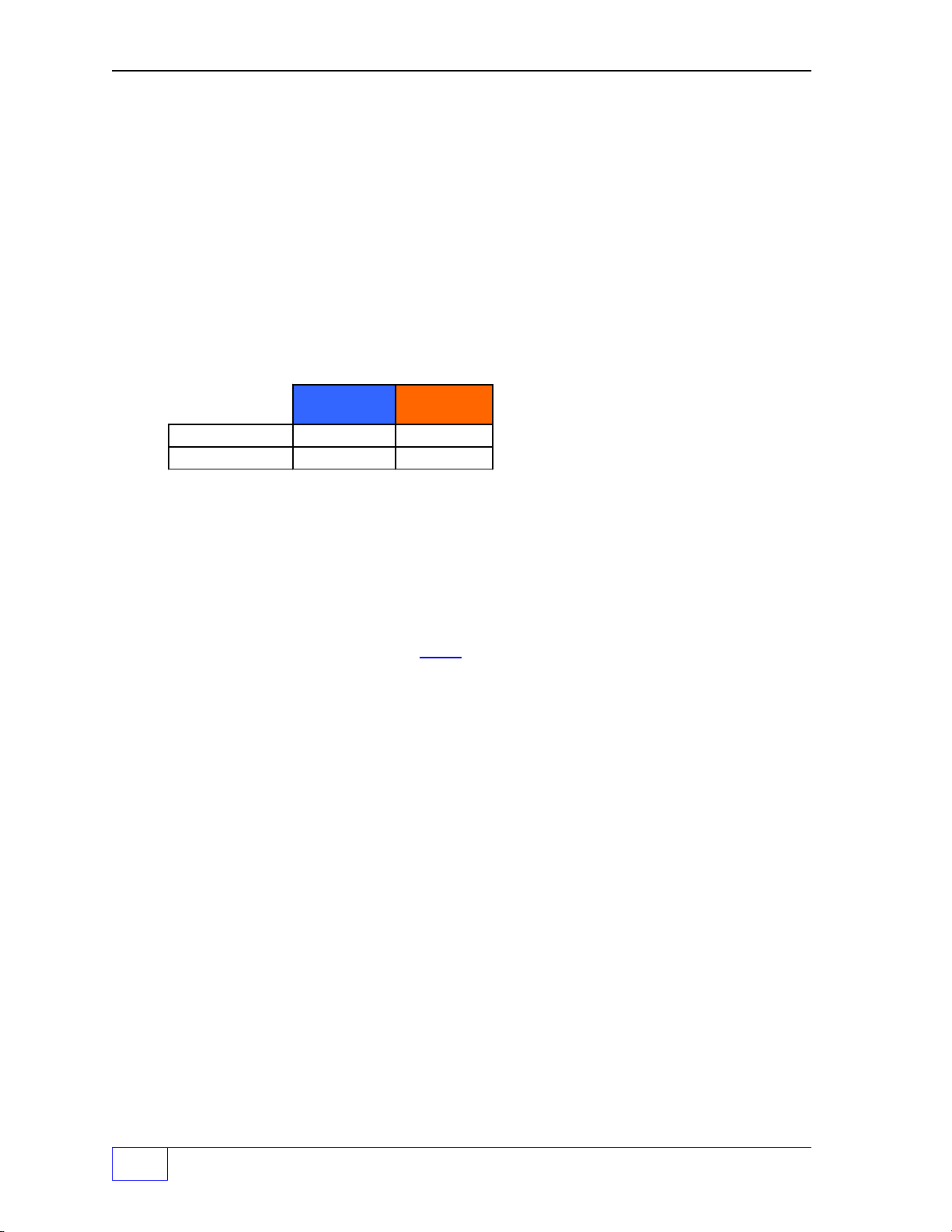
SCALD (tank leak) Test Menu
SCALD TESTS
CONFIDNCE
SCALD CONFIDENCE
99.0% Keep the default 99.0% value
90.0%
95.0%
97.5% Press
PRECISION
SCALD TEST PRECISION
+0.2 Keep the default 0.2 gph monthly test value
SCALD Leak Test:
Precision:
INTERVAL
SCALD INTERVAL
18 Keep the default value (18
Monthly
Compliance
0.2 gph 0.1 gph
Threshold = 1/2 of Leak Test value
Yearly Test
Press
Press
N = Tanks 1 – 8
programmed in the System menu will appear)
ENTER
ENTER
ENTER
to accept this data.
to accept this data.
to accept this data.
(only the NO. of TANKS
)
QUALIFY (minimum volume percent before starting a test)
SCALD VOLUME QUALIFY
NOTE
+0
Use keypad to input a percentage.
Press
Reference Local codes (and/or State / Province /
0.0 to 99.0%
ENTER
to accept this data.
Federal codes) for the minimum percentage of
☞
tank-volume-capacity before a leak test results
can, or will, be considered acceptable. Input the
minimum-acceptable volume based on these
regulations.
ENABLE (select tanks to be SCALD leak tested)
SCALD ENABLE
TANK 1
TANK 2 Use
:
TANK 8 Press the (
SCALD ENABLE
ENABLED
DISABLED Press
Keep the default – all tanks ENABLED
UP/DOWN
Use
UP/DOWN
ENTER
▲ ▼ keys to show more choices.
M
) key to select a TANK #.
▲ ▼ keys to change the setting.
to accept this data.
11
Press the
Page 11- 2 Tank Sentinel Setup Programming Guide
CANCEL
key to return to the SCALD TESTS menus.
— C
ONTINUED ON NEXT PA G E
—
Page 76

SCALD (tank leak) Test Menu (C
VAPOR RECOVERY (select ENABLED when Vapor Recovery is present)
SCALD VAPOR RECOVERY
DISABLED
ENABLED Press
ALARM ON (change to YES if you want an alarm when a SCALD
ALARM ON SCALD FAIL leak test fails)
NO
YES Press
ONTINUED
Use
UP/DOWN
ENTER
(Enable for vapor recovery systems)
Use
UP/DOWN
ENTER
....
FROM PREVIOUS PAG E
▲ ▼ keys to show choices.
to accept this data.
▲ ▼ keys to show choices.
to accept this data.
)
TST FL OG (
SCALD FAIL OUTPUT GROUP FAIL – YES was chosen above)
TANK 1
TANK 2 Press the (
: Use
TANK 8
SCALD TEST FAIL OUTPUT GROUP N (32 OGs available ...
NONE
GROUP A-FF One OG selected (A=1st OG, FF=32nd OG)
ALL GROUPS All OGs selected
This menu appears only when ALARM ON SCALD
*
M
) key to select a TANK #.
UP/DOWN
Not assigned to an output group (OG).
Use
UP/DOWN
Press
ENTER
▲ ▼ keys to show more choices.
▲ ▼ keys to show more choices.
to accept this data.
— Your Notes —
see WORKSHEET # 8-1.)
—
SCALD Tank Leak Test Setup Page 11 - 3
❖
—
11
Page 77
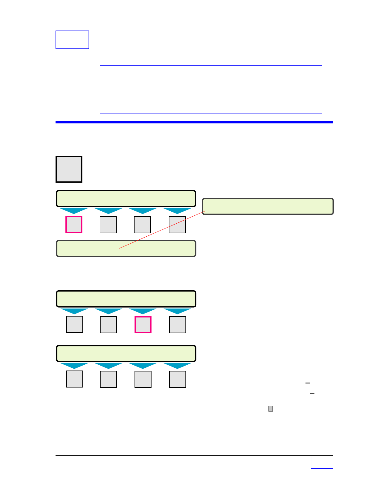
12 Line T ests
SELECT MENU OPTION
SETUP UPGRADE LANGUAGE DATALOG
SETUP MENU (MORE)
EXIT SYSTEM TANKS LINES
SYSTEM INFO (MORE)
NO. LINES NO. SENS LIMITS SENTINEL
SETUP MENU (MORE)
LK TESTS SCLD TEST
LN TESTS
CLK/CAL
LINE TESTS
SCHEDULE FAIL OG FAULT OG
SETUP PROGRAMMING
Contents:
LN (Line) leak Test Menu
Line Leak Test Requirements
TABLE 12.1 Time Input
Output Group Assignments
Worksheet 12 - 1
LN (Line) Tests Menu
H U
MENU
7
× Press this key and follow the
highlighted sequence below
M1 M2 M3 M4
See the Table of Contents to find topics in
this manual. See the Preface for general
information about this manual. And see the
Installation, Operator’s, TroubleShooting
Guides, and Application Notes for other
reference material.
NOTE
Disregard this Chapter if the LN TESTS menu does
not appear. Note that the position of this menu can
☞
be displaced by other menus.
The LN TESTS and LINES menu, only appear if
one or more NO. LINES are entered under the
SYSTEM setup menu.
The TS-LLD Line Leak Detector automatically
performs a 0.2 gph (monthly compliance) test
every 24 hours.
Press the
DO WN
▼ key until the
LN TESTS menu is displayed
M1 M2 M3 M4
M1 M2 M3 M4
With this menu you may control the time this
happens or schedule it to happen at a different time
or day than tank leak tests run (to avoid affecting
tank leak test results).
Character input / editing:
•
Push
UP/DOWN
menus or menu selections.
•
Use menu keys
menus.
•
Press
ENTER
value into the setup configuration memory.
•
Press
CANCEL
•
Press
M1
•
Use
M2
to move the cursor right
•
Press
M4
character to the left
▲ ▼ keys to show more
(M1
to
M4)
to access
to accept a selection or input a
to cancel data entry
to move the cursor left
to backspace (delete) one
ï
ï
ð
— Continued on next page —
Clock / Calendar Setup Page 12 - 1
12
Page 78
Line Leak Test Requirements & Notes:
TABLE 12.1 24 Hour Time Input Format
HH:MM:SS
00:00:00 = midnight 22:00:00 = 10 pm + 12 ( hours )
( add 12 hours to pm times starting at 1 pm to 11:59 pm )
02:05:00 = 2:05 am
y
p
g
g
1) Inform the Site Personnel to: (If the store closes at night - not 24-hour) Leave the
Pump Controllers power on at night with dispenser power off. The Submerged
Turbine Pump (STP) must be able to turn on to run the pressurized line leak tests.
2) It is recommended that Line Leak Tests and Tank Leak Tests should not be
scheduled to run at the same time. See Chapter 8 for Tank Leak Test scheduling.
3) Note: The 0.2 gph Line Leak Test will normally finish during quiet-times between
product dispensing. (The line leak detector may start the pump at any time to run
pressurized line leak tests.)
4) The 0.1 precision line leak test requires 4 hours of quiet-time (after the final
dispense) before it will run successfully. Make sure to take this into account
when scheduling a Annual precision 0.1 Line Leak Test.
5) Note: See the TS-LLD Manual or consult INCON Technical Service for Special
Applications (for example: manifolded lines, nonstandard pumps, etc.).
6) Before programming, reference the State and Local Regulations about line leak testing,
type / precision of the tests, test frequency, and reporting requirements... adhere to
these requirements.
Type /
Precision
Monthl
Com
liance
Annual /
Yearly
Line Leak
Test
— Your Notes —
ph 0.1
0.2
ph
12
Page 12 - 2 Tank Sentinel Setup Programming Guide
Page 79

LN Line (leak) Tests Menu ( Continued from page 1 )
*
Only the No. of lines that are programmed in System menu are displayed
SCHEDULE Press the
SELECT A LINE
LINE 1
LINE 2
LINE 8
LINE TEST SCHEDULE N Program a Schedule and Time for each Line#
*
:
*
*
SCHED 0.1
NONE
DAILY
MONDAY Use
:
SUNDAY Press
1 ST DAY No Dispensing is allowed during this schedule*
:
30 TH DAY
LAST DAY
TIME 0.1
0.1 GPH LINE TEST TIME N
00:00:00 24 HOUR FORMAT See TABLE 12.1
Use (M) keys to select a LINE#.
Use
0.1 = Precision Annual Line Leak Test
No schedule / not scheduled
NOTE: February does not have 30 days !
See Test Requirements and Notes !
Use keypad to input 24-hour time data.
Press
M1
UP/DOWN
UP/DOWN
ENTER
ENTER
key.
▲ ▼ keys to show more choices.
▲ ▼ keys to show more choices.
to accept this data.
to accept this data.
NOTE
☞
SCHED 0.2
NONE
DAILY
MONDAY Use
:
SUNDAY Press
1 ST DAY Dispensing allowed during this schedule.
:
30 TH DAY
LAST DAY
TIME 0.2
0.1 GPH LINE TEST TIME N
00:00:00 24 HOUR FORMAT See TABLE 12.1
0.2 = Monthly Compliance Line Leak Test
No schedule / not scheduled
NOTE: February does not have 30 days !
See Test Requirements and Notes !
Use keypad to input 24-hour time data.
Press
— C
ONTINUED ON NEXT PA G E
Both the 0.1 & 0.2 gph line leak tests can be
programmed for a particular Line or all Lines.
But, the schedule and times must be different !
Also see Test Requirements and Notes.
UP/DOWN
ENTER
ENTER
▲ ▼ keys to show more choices.
to accept this data.
to accept this data.
—
Clock / Calendar Setup Page 12 - 3
12
Page 80

LN Line (leak) Tests Menu ( Continued... )
*
Only the No. of lines that are programmed in System menu are displayed
FAIL OG (Will go Active when any (3 gph, 0.2 gph, and 0.1 gph)
LINE TEST FAIL OUTPUT GROUP Line Leak Test fails)
LINE 1
LINE 2
LINE 8
LINE TEST FAIL OUTPUT GROUP N (32 Output Groups (OGs) available...
FAULT OG (Will go active when a fault (TS-LLD flashing alarm
LINE TEST FAIL OUTPUT GROUP error-code) occurs)
LINE 1
LINE 2
LINE 8
LINE TEST FAULT OUTPUT GROUP N (32 Output Groups (OGs) available...
*
:
*
*
Press (M) key to select a LINE#.
Use
UP/DOWN
▲ ▼ keys to show more choices.
See Worksheet 12-1)
NONE
GROUP A-FF One OG selected (A=1st OG, FF=32nd OG)
ALL GROUPS All OGs selected
*
:
*
*
Not assigned to an Output Group (OG).
Use
UP/DOWN
Press
ENTER
Press (M) key to select a LINE#.
Use
UP/DOWN
▲ ▼ keys to choose an OG.
to accept this data.
▲ ▼ keys to show more choices.
See Worksheet 12-1)
NONE
GROUP A-FF One OG selected (A=1st OG, FF=32nd OG)
ALL GROUPS All OGs selected
Not assigned to an Output Group (OG).
Use
UP/DOWN
Press
ENTER
▲ ▼ keys to choose an OG.
to accept this data.
12
— Your Notes —
Page 12 - 4 Tank Sentinel Setup Programming Guide
Page 81
Worksheet # 12-1 – Output Groups – Line Leak Tests
Fill-in the worksheet below. Compare assignments with other worksheets to uncover
conflicts before programming the output devices.
OG = Output Group
Line Leak Test:
FAIL OG Line 1
FAIL OG Line 2
FAIL OG Line 3
FAIL OG Line 4
FAIL OG Line 5
FAIL OG Line 6
FAIL OG Line 7
FAIL OG Line 8
TS-LLD
Line Leak Detector:
FAULT OG Line 1
FAULT OG Line 2
FAULT OG Line 3
FAULT OG Line 4
FAULT OG Line 5
FAULT OG Line 6
FAULT OG Line 7
FAULT OG Line 8
- Output Group Assignment WORKSHEET Output Group choices -
Example:
Line Leak Test:
FAIL OG Line 2
Line Leak Detector:
FAULT OG Line 2
Output Devices: Modulated Annunciator, Solid Annunciator, Relay 1, Relay 2, I/O Output Module
Channel # 1 to # __ (record all OG Assignments in the vertical column)
Activates Modulated Annunciator & Relay 2 (turns on line leak light)
L
Activates Solid Annunciator (for 20 seconds)
F
NONE
A
B
C
D
E
F
G
H
I
J
K
L
M
N
O
P
Q
R
S
T
U
V
W
X
Y
Z
AA
BB
CC
DD
EE
FF
ALL
—
❖
—
Clock / Calendar Setup Page 12 - 5
12
Page 82

13 Clock / Calendar
SELECT MENU OPTION
SETUP UPGRADE LANGUAGE DATALOG
SETUP MENU (MORE)
EXIT SYSTEM TANKS PROBES
SETUP MENU (MORE)
SCLD TEST
CLK/CAL
ANNUNC RELAYS
CLOCK/CALENDAR (MORE)
DAY SAV TM STYLE DT STYLE SET TIME
CLOCK/CALENDAR (MORE)
SET DATE SET DAY
SETUP PROGRAMMING
Contents:
Clock Calandar Menu
TABLE 13.1 24 Hour Time
Input Format
Clock / Calendar Menu
H U
MENU
7
M1 M2 M3 M4
× Press this key and follow the
highlighted sequence below
See the Table of Contents to find topics in
this manual. See the Preface for general
information about this manual. And see the
Installation, Operator’s, TroubleShooting
Guides, and Application Notes for other
reference material.
NOTE
☞
The Clock and Calendar menu must be set —
DO NOT skip this menu. Program the Date
and Time accurately.
Remember:
•
Push
UP/DOWN
menus or menu selections.
•
Use menu keys
menus.
•
Press
ENTER
value into the setup configuration memory.
keys ▲ ▼ to show more
(M1
to
M4)
to accept a selection or input a
to access
Press
DOWN
▼ key a few times or until the
CLK/CAL menu is displayed
M1 M2 M3 M4
M1 M2 M3 M4
M1 M2 M3 M4
•
Press
CANCEL
to cancel data entry.
Character input / editing:
•
Press
M1
to move the cursor left
•
Use
M2
to move the cursor right
•
Press
M4
to backspace (delete) one charac-
ter to the left
Press the (M) key under each of these menu
items to enter the proper settings.
ï
— Continued on next page —
ï
ð
Clock / Calendar Setup Page 13 - 1
13
Page 83

Clock / Calendar Menu
TABLE 13.1 24 Hour Time Input Format
HH:MM:SS
00:00:00 = midnight
22:00:00 = 10 pm + 12 ( hours )
( add 12 hours to pm times starting at 1 pm to 11:59 pm )
02:05:00 = 2:05 am
CLOCK/CALENDAR
DAY SAV Press
DAYLITE SAVINGS Use
ENABLED
DISABLED Disable = does not
TM STYLE (Select the time style - (12 or 24 hour) for display,
TIME STYLE reports and faxes)
12 HOUR
24 HOUR Press
DT STYLE (Select the date style - (Month/Day/Year) for display,
DATE STYLE reports and faxes.)(YY = Year, MM = Month, DD = Day)
MM/DD/YY
DD/MM/YY
YY/MM/DD Press
SET TIME (Input current time in 24-hour format)
SET SYSTEM TIME 2 digits are required for hours, minutes, seconds –
HH:MM:SS
M1
key.
UP/DOWN
Enable = allows daylight savings time changes
Press
ENTER
Use
UP/DOWN
ENTER
Use UP/DOWN
ENTER
use leading zeros before single digits,
(for example input ‘05’ not ‘5’)
Use keypad to input time data.
Press
ENTER
▲ ▼ keys to show choices.
key to accept this data.
▲ ▼ keys to show choices.
key to accept this data.
▲ ▼ keys to show choices.
key to accept this data.
key to accept this data.
SET DATE
SET SYSTEM DATE (Input current DATE )
YYYY:MM:DD
SET DAY
SET SYSTEM DAY OF WEEK (Select the current day of the week)
SUNDAY
MONDAY Use
TUESDAY Press
WEDNESDAY
THURSDAY
FRIDAY
13
SATURDAY
Page 13 - 2 Tank Sentinel Setup Programming Guide
(YYYY = year, MM = Month, DD = Day)...
2 digits are required for month and day –
use leading zeros before single digits,
(for example input ‘04’ not ‘4’)
Use keypad to input DATE data.
Press
ENTER
UP/DOWN
ENTER
to accept this data.
▲ ▼ keys to show choices.
to accept this data.
Page 84

— Your Notes —
—
Clock / Calendar Setup Page 13 - 3
❖
—
13
Page 85

14 Annunciator
SETUP MENU (MORE)
EXIT SYSTEM TANKS PROBES
ANNUNCIATORS
MODULATED SOLID TEST
SETUP MENU (MORE)
SCLD TEST CLK/CAL
ANNUNC
RELAYS
SELECT MENU OPTION
SETUP
UPGRADE LANGUAGE DATALOG
SETUP PROGRAMMING
Contents:
Annunciator Menu
Annunciator Timeout
Modulated & Solid Annunciator
Output Groups and Alarm
Assignments
See the Table of Contents to find topics in
this manual. See the Preface for general
information about this manual. And see the
Installation, Operator’s, TroubleShooting
Guides, and Application Notes for other
reference material.
Annunciator Menu (Console Alarm Horn)
H U
MENU
7
M1 M2 M3 M4
× Press this key and follow the
highlighted sequence below
The annunciator menu must be set (DO NOT skip
this menu). The annunciator
that produces
of a problem (flashing warning or alarm lights on
the console also provide visual indications).
Two sounds can be produced: a modulated
(beeping) or a continuous (solid) tone. Any Alarm
Output Group
annunciator horn.
NOTE
☞
is an Output Device
an audible alarm to alert attendants
can be programmed to sound the
See Worksheets for applicable Output
Group assignments. Use the Table of
Contents (TOC) to locate Worksheets.
Press
DOWN
▼ key twice ( 2 X )
M1 M2 M3 M4
M1 M2 M3 M4
MODULATED ANNUNCIATOR
TIMEOUT
MODULATED ANNUNCIATOR TIMEOUT
0
Remember:
•
Push
UP/DOWN
menus or menu selections.
•
Use menu keys
menus.
•
Press
ENTER
value into the setup configuration memory.
•
Press
CANCEL
to accept a selection or input a
to cancel data entry
Annunciator Time-out
Input a
value (i.e. 10 seconds) – especially if
NOTE
☞
Use keypad to input a value.
Press
ENTER
an acknowledge password is required
before an alarm can be silenced. Also
see the Relays Setup Chapter and input
relay time-outs if external alarm
annunciators are used.
0 to 3600
to accept this data.
considerable
▲ ▼ keys to show more
(M1
to
M4)
to access
alarm time-out
!!
(Input an automatic time-out / turn-off value in seconds... Ø = no time-out, the
attendant must press
ACK
to silence alarms, 3600 = 60 minutes or 1 hour time-out )
Annunciator Setup Page 14 - 1
14
Page 86

Annunciators Menu (C
ONTINUED
...
FROM PREVIOUS PAGE
)
Modulated Annunciator Output Group (alarm assignment)
MODULATED
MODULATED ANNUNCIATOR – Continued – Select / assign output group(s) to activate
OUT GRPS the modulated annunciator on alarm.
MODULATED ANNUNCIATOR OUTPUT GROUPs GROUP
– – – – – – – – – – – – – – – – – – – – – – – – – – – – – – – – – –
1 32
A B C D E F G H I J K L M N O P Q R S T U V W X Y Z AA BB CC DD EE FF
Fill–in Modulated Annunciator Output – Group Assignments Below:
A B C D E F G H I J K L M N O P Q R S T U V W X Y Z A A B B C C D D E E F F
Example Output Device — OUTPUT GROUP Assignment (shown filled-in)
ABCDEFGH I JKLMNOPQRSTUVWXYZA AB BC C D DE EF F
Y YYY Y
OUTPUT GROUP GROUP
Y – – Y Y Y – –
1 32
A B C D E F G H I J K L M N O P Q R S T U V W X Y Z AA BB CC DD EE FF
– – – – – – – – – – – – – – – Y – – – – – – – – X
A
The 24TH group
(Group X) is shown
assigned
Y
Press:M1 to move the cursor left
M2
NOTE
☞
to move the cursor right
UP / DOWN
ENTER
▲▼ to select (Y for yes assigned, or
to store the setup into the system memory
ï
ð
M4
to backspace (delete) one character to the left
–
(dash) for no not assigned)
SOLID (Go back to ANNUNCIATORS menu and push the
SOLID ANNUNCIATOR TIMEOUT
M2
menu key (under SOLID) to access this menu)
TIMEOUT
0
0 to 3600
(Input an automatic time-out / turn-off value in seconds...
0 = no time-out, the attendant must press
alarms, 3600 = 60 minutes or 1 hour time-out )...
ACK
to silence
see
note on first page of this chapter.
Solid Annunciator Output Group (alarm assignment)
Select / assign output group(s) to activate
OUT GRPS the solid tone annunciator on alarm.
SOLID ANNUNCIATOR OUTPUT GROUPS GROUP
– – – – – – – – – – – – – – – – – – – – – – – – – – – – – – – – – –
1 32
A B C D E F G H I J K L M N O P Q R S T U V W X Y Z AA BB CC DD EE FF
Fill–in Solid Annunciator Output – Group Assignments Below:
A B C D E F G H I J K L M N O P Q R S T U V W X Y Z A A B B C C D D E E F F
A
ï
14
Page 14 - 2 Tank Sentinel Setup Programming Guide
Page 87

Annunciator Testing
TEST
HIT ANY KEY TO QUIT
NOTE
☞
INCON Recommends that you program one of the
annunciators to react to system fail warnings and any leak
detection sensors and leak test fail alarms
• Test the Modulated ALARM HORN ANNUNCIATOR
Go back to the ANNUNCIATORS menu and push the
menu key (under TEST) to activate the horn. The horn will
stop when the modulated annunciator timeout value is
reached – or – when any other key is pressed.
• Test the Solid ALARM HORN ANNUNCIATOR
.
M3
NOTE
☞
The solid alarm horn annunciator can be tested from the front
panel by exiting SETUP and pressing the ALARM TEST key
(only in the normal Run Mode).
solid annunciator timeout value is reached – or – when any
other key is pressed.
— Your Notes —
The horn will stop when the
—
Annunciator Setup Page 14 - 3
❖
—
14
Page 88

15 Relays SETUP PROGRAMMING
SETUP MENU (MORE)
EXIT SYSTEM TANKS PROBES
SELECT MENU OPTION
SETUP
UPGRADE LANGUAGE DATALOG
SETUP MENU (MORE)
SCLD TEST CLK/CAL ANNUNC
RELAYS
RELAYS
RELAY 1 RELAY 2
Contents:
Relay Menu
Relay Timeout
Relay 1 & 2 Output Groups
Alarm Assignments
Relay Menu
H U
MENU
7
× Press this key and follow the
highlighted sequence below
M1 M2 M3 M4
See the Table of Contents to find topics in
this manual. See the Preface for general
information about this manual. And see the
Installation, Operator’s, TroubleShooting
Guides, and Application Notes for other
reference material.
RELAY OUTPUT DEVICES
RELAY 1
OUTPUT GROUP
RELAY 2
OUTPUT GROUP
LOADS
NC 1
C1
NO 1
NC 2
C2
NO 2
– EITHER
turn off
with alarm
OR
turn on
with alarm
The relay menu provides the means to control
external devices, such as a Remote Alarm unit that
alerts attendants of a problem (alarm or limit). Two
available output relays can be used for this
purpose.
The loads will switch on / off in response to alarms
that are assigned to
output groups
(depending on
how they are wired)... see the diagram above.
Press the
M1 M2 M3 M4
M1 M2 M3 M4
DOWN
▼ key once ...
RELAY 1 Press M1 key.
M1
TIMEOUT Press
key.
RELAY TIMEOUT 1
15
0 to 3600 (Input an automatic relay time-out / switch-
NOTE
See Worksheets for applicable Output
Group assignments. Use the Table of
☞
Contents (TOC) to locate Worksheets.
Character input / editing:
•
Push
UP/DOWN
menus or menu selections.
•
Use menu keys
menus.
•
Press
ENTER
value into the setup configuration memory.
•
Press
CANCEL
Relay Timeout Note #A
Input a
time-out value –
relay controls an external alarm device.
off value in seconds... 0 = no time-out,
the attendant must press
relay off, 3600 = 60 minutes or 1 hour timeout )
considerable
▲ ▼ keys to show more
(M1
to
M4)
to access
to accept a selection or input a
to cancel data entry
!!
automatic relay
especially when the
ACK
to switch the
— Continued on next page —
Relays Setup Page 15 - 1
15
Page 89

Relay Menu (C
ONTINUED
...
FROM PREVIOUS PAGE
)
Relay 1 Output Group (alarm assignment)
Select / assign output group(s) to activate RELAY 1 on alarm / limit.
RELAY 1
OUT GRPS
RELAY OUTPUT GROUPS 1 GROUP
– – – – – – – – – – – – – – – – – – – – – – – – – – – – – – – – – –
1 32
A B C D E F G H I J K L M N O P Q R S T U V W X Y Z AA BB CC DD EE FF
Fill–in RELAY 1 Output – Group Assignments Below:
A B C D E F G H I J K L M N O P Q R S T U V W X Y Z A A B B C C D D E E F F
TEST Relay 1 Press M3 key.
TESTING... RELAY switches on and off...
HIT ANY KEY TO QUIT
Example Output Device — OUTPUT GROUP Assignment (shown filled-in)
Press any key to stop the test or wait for the time-out to
switch the relay off
if the time-out value is greater than Ø
A
listen for clicking sound.
.
ABCDEFGH I JKLMNOPQRSTUVWXYZA AB BC C D DE EF F
Y YYY Y
Y – – Y Y Y – –
1 32
A B C D E F G H I J K L M N O P Q R S T U V W X Y Z AA BB CC DD EE FF
Press:M1 to move the cursor left
NOTE
☞
M2
to move the cursor right
Use
UP / DOWN
Press ENTER
OUTPUT GROUP GROUP
– – – – – – – – – – – – – – – Y – – – – – – – – X
ï
ð
M4
to backspace (delete) one character to the left
▲▼ to select (Y for yes assigned, or
to store the setup into the system memory.
Relay Timeout Note #B
–
!!
The 24TH group
(Group X) is shown
assigned
(dash) for no not assigned).
Y
ï
When using a relay output in combination with a TS-RK ( Remote alarm
Acknowledge unit) and a TS-RA1 or TS-RA2 (Remote Alarm unit) to
monitor overfill of multiple tanks, you must set a reasonable relay timeout value.
without the need for someone to press the
Do this so the relay will react to overfill alarms from each tank
ACK
key after each overfill.
15
Page 15- 2 Tank Sentinel Setup Programming Guide
Page 90

Relay Menu (C
ONTINUED
...
FROM PREVIOUS PAGE
)
RELAY 2 Go back to RELAYS menu and push M2 under
TIMEOUT RELAY 2 to access this menu.
RELAY TIMEOUT 2
15
0 to 3600
(Input an automatic relay time-out / switch-off value in
seconds... 0 = no time-out, the attendant must press
ACK
to switch the relay off, 3600 = 60 minutes or 1 hour
time-out )... Input a
out value –
especially when the relay controls an
considerable
automatic relay time-
external alarm device.
Relay 2 Output Group (alarm assignment)
Select / assign output group(s) to activate RELAY 1 on alarm / limit.
OUT GRPS
RELAY OUTPUT GROUPS 1 GROUP
– – – – – – – – – – – – – – – – – – – – – – – – – – – – – – – – – –
1 32
A B C D E F G H I J K L M N O P Q R S T U V W X Y Z AA BB CC DD EE FF
Fill–in RELAY 2 Output – Group Assignments Below:
A B C D E F G H I J K L M N O P Q R S T U V W X Y Z A A B B C C D D E E F F
A
TEST Relay 2 Press M3 key.
TESTING... RELAY switches on and off...
HIT ANY KEY TO QUIT
Press any key to stop the test or wait for the time-out to
switch the relay off
if the time-out value is greater than Ø
listen for clicking sound.
.
Relays Setup Page 15 - 3
15
Page 91

— Your Notes —
15
—
Page 15- 4 Tank Sentinel Setup Programming Guide
❖
—
Page 92

16 TS-ROM Relay Output Module
SETUP MENU (MORE)
EXIT SYSTEM TANKS PROBES
SELECT MENU OPTION
SETUP
UPGRADE LANGUAGE DATALOG
SETUP MENU (MORE)
TS-ROM
SENSORS AUX INPUT IO MODULE
TS-ROM (MORE)
GRACE PRD CHANNEL 1 CHANNEL 2 CHANNEL 3
SETUP PROGRAMMING
Contents:
TS-ROM Menu
Grace Period
TS-ROM Channel 1–8 Output
Groups Alarm Assignments
TS-ROM Menu
H U
MENU
7
M1 M2 M3 M4
× Press this key and follow the
highlighted sequence below
See the Table of Contents to find topics in
this manual. See the Preface for general
information about this manual. And see the
Installation, Operator’s, TroubleShooting
Guides, and Application Notes for other
reference material.
This menu appears only after the TS-ROM
BriteBox™ is installed, and after console power
is turned on (disregard this Chapter if a TS-ROM
is not installed).
The TS-ROM relay menu provides the means to
control external devices (such as STPs). The
TS-ROM has 4 or 8 output channel relays that
can be used for this purpose.
Channel relays (and the external devices wired
to these) will switch on / off in response to alarms
that are assigned to the relay
NOTE
The installer must document the use for
output groups
each channel-relay, the device that each
☞
controls, proper action or operation, and
the power source.
.
See Worksheets for applicable Output Group
assignments. Use the Table of Contents (TOC)
to locate Output Group Worksheets.
Press
DOWN
▼ key two or three times...
Grace Period
Grace Period is an
programmed interval of time (in minutes).
M1 M2 M3 M4
Input the smallest possible grace period.
Consider the actions for all external devices that
are wired to the TS-ROM relays.
device cannot have an override grace period, then
leave the grace period at 0 for no override.
If used to disable dispensing when product levels
M1 M2 M3 M4
TS-ROM
TS-ROM GRACE PERIOD Allows normal operation for a short time
0
(Input time for relay to remain closed) Pressing
starts the grace period and overrides the alarm-lockout on
the TS-ROM channel relay.
are low or water levels high, then be sure to set
the grace period to a minimum (to prevent the
pump from running dry and overheating, or to
prevent pumping water).
0 to 120 minutes
alarm override for a
If one external
ACK
TS-ROM Setup Page 16 - 1
16
Page 93

TS-ROM Menu (C
ONTINUED
...
FROM PREVIOUS PAGE
)
Example Output Device — OUTPUT GROUP Assignment (shown filled-in)
ABCDEFGH I JKLMNOPQRSTUVWXYZA AB BC C D DE EF F
Y YYY Y
Y – – Y Y Y – –
1 32
A B C D E F G H I J K L M N O P Q R S T U V W X Y Z AA BB CC DD EE FF
Press:M1 to move the cursor left
NOTE
☞
– – – – – – – – – – – – – – – Y – – – – – – – – X
ï
M2
to move the cursor right
UP / DOWN
ENTER
▲▼ to select (Y for yes assigned, or
to store the setup into the system memory
ð
M4
to backspace (delete) one character to the left
–
(dash) for no not assigned)
OUTPUT GROUP GROUP
The 24TH group
(Group X) is shown
assigned
Y
TS-ROM Channel 1 Output Group (alarm assignment)
CHANNEL 1
TS-ROM CHANNEL 1 Select / assign output group(s) to activate
OUT GRPS the TS-ROM Channel Relay 1 on alarm
TS-ROM OUTPUT GROUPS 1 GROUP
– – – – – – – – – – – – – – – – – – – – – – – – – – – – – – – – – –
1 32
A B C D E F G H I J K L M N O P Q R S T U V W X Y Z AA BB CC DD EE FF
Fill–in TS-ROM Channel Relay 1 Output – Group Assignments Below:
A B C D E F G H I J K L M N O P Q R S T U V W X Y Z A A B B C C D D E E F F
A
ï
TS-ROM Channel 2 Output Group (alarm assignment)
CHANNEL 2
TS-ROM CHANNEL 2 Select / assign output group(s) to activate
OUT GRPS the TS-ROM Channel Relay 2 on
TS-ROM OUTPUT GROUPS 2 GROUP
– – – – – – – – – – – – – – – – – – – – – – – – – – – – – – – – – –
1 32
A B C D E F G H I J K L M N O P Q R S T U V W X Y Z AA BB CC DD EE FF
A
Fill–in TS-ROM Channel Relay 2 Output – Group Assignments Below:
A B C D E F G H I J K L M N O P Q R S T U V W X Y Z A A B B C C D D E E F F
TS-ROM Channel 3 Output Group (alarm assignment)
CHANNEL 3
TS-ROM CHANNEL 3 Select / assign output group(s) to activate
OUT GRPS the TS-ROM Channel Relay 3 on alarm
TS-ROM OUTPUT GROUPS 3 GROUP
– – – – – – – – – – – – – – – – – – – – – – – – – – – – – – – –
1 32
A B C D E F G H I J K L M N O P Q R S T U V W X Y Z AA BB CC DD EE FF
Fill–in TS-ROM Channel Relay 3 Output – Group Assignments Below:
A B C D E F G H I J K L M N O P Q R S T U V W X Y Z A A B B C C D D E E F F
A
16
Page 16 - 2 Tank Sentinel Setup Programming Guide
Page 94

TS-ROM Channel 4 Output Group (alarm assignment)
CHANNEL 4
TS-ROM CHANNEL 4 Select / assign output group(s) to activate
OUT GRPS the TS-ROM Channel Relay 4 on alarm
TS-ROM OUTPUT GROUPS 4 GROUP
– – – – – – – – – – – – – – – – – – – – – – – – – – – – – – – – – –
1 32
A B C D E F G H I J K L M N O P Q R S T U V W X Y Z AA BB CC DD EE FF
A
Fill–in TS-ROM Channel Relay 4 Output – Group Assignments Below:
A B C D E F G H I J K L M N O P Q R S T U V W X Y Z A A B B C C D D E E F F
TS-ROM Channel 5 Output Group (alarm assignment)
CHANNEL 5
TS-ROM CHANNEL 5 Select / assign output group(s) to activate
OUT GRPS the TS-ROM Channel Relay 5 on alarm
TS-ROM OUTPUT GROUPS 5 GROUP
– – – – – – – – – – – – – – – – – – – – – – – – – – – – – – – – – –
1 32
A B C D E F G H I J K L M N O P Q R S T U V W X Y Z AA BB CC DD EE FF
Fill–in TS-ROM Channel Relay 5 Output – Group Assignments Below:
A B C D E F G H I J K L M N O P Q R S T U V W X Y Z A A B B C C D D E E F F
A
TS-ROM Channel 6 Output Group (alarm assignment)
CHANNEL 6
TS-ROM CHANNEL 6 Select / assign output group(s) to activate
OUT GRPS the TS-ROM Channel Relay 6 on alarm
TS-ROM OUTPUT GROUPS 6 GROUP
– – – – – – – – – – – – – – – – – – – – – – – – – – – – – – – – – –
1 32
A B C D E F G H I J K L M N O P Q R S T U V W X Y Z AA BB CC DD EE FF
A
Fill–in TS-ROM Channel Relay 6 Output – Group Assignments Below:
A B C D E F G H I J K L M N O P Q R S T U V W X Y Z A A B B C C D D E E F F
TS-ROM Channel 7 Output Group (alarm assignment)
CHANNEL 7
TS-ROM CHANNEL 7 Select / assign output group(s) to activate
OUT GRPS the TS-ROM Channel Relay 7 on alarm
TS-ROM OUTPUT GROUPS 7 GROUP
– – – – – – – – – – – – – – – – – – – – – – – – – – – – – – – – – –
1 32
A B C D E F G H I J K L M N O P Q R S T U V W X Y Z AA BB CC DD EE FF
Fill–in TS-ROM Channel Relay 7 Output – Group Assignments Below:
A B C D E F G H I J K L M N O P Q R S T U V W X Y Z A A B B C C D D E E F F
A
TS-ROM Setup Page 16 - 3
16
Page 95

TS-ROM Menu (C
ONTINUED
...
FROM PREVIOUS PAGE
)
Example Output Device — OUTPUT GROUP Assignment (shown filled-in)
ABCDEFGH I JKLMNOPQRSTUVWXYZA AB BC C D DE EF F
Y YYY Y
Y – – Y Y Y – –
1 32
A B C D E F G H I J K L M N O P Q R S T U V W X Y Z AA BB CC DD EE FF
Press:M1 to move the cursor left
NOTE
☞
– – – – – – – – – – – – – – – Y – – – – – – – – X
ï
M2
to move the cursor right
UP / DOWN
ENTER
▲▼ to select (Y for yes assigned, or
to store the setup into the system memory
ð
M4
to backspace (delete) one character to the left
–
(dash) for no not assigned)
OUTPUT GROUP GROUP
The 24TH group
(Group X) is shown
assigned
Y
TS-ROM Channel 8 Output Group (alarm assignment)
CHANNEL 8
TS-ROM CHANNEL 8 Select / assign output group(s) to activate
OUT GRPS the TS-ROM Channel Relay 8 on alarm
TS-ROM OUTPUT GROUPS 8 GROUP
– – – – – – – – – – – – – – – – – – – – – – – – – – – – – – – – – –
1 32
A B C D E F G H I J K L M N O P Q R S T U V W X Y Z AA BB CC DD EE FF
Fill–in TS-ROM Channel Relay 8 Output – Group Assignments Below:
A B C D E F G H I J K L M N O P Q R S T U V W X Y Z A A B B C C D D E E F F
A
ï
— Your Notes —
—
❖
—
16
Page 16 - 4 Tank Sentinel Setup Programming Guide
Page 96

17 Sensors (Leak Detection)
SELECT MENU OPTION
SETUP
UPGRADE LANGUAGE DATALOG
SETUP MENU (MORE)
EXIT SYSTEM TANKS PROBES
SENSORS (MORE)
AUTO CFG SENSOR 1 SENSOR 2 SENSOR 3
SETUP MENU (MORE)
TS-ROM
SENSORS
AUX INPUT IO MODULE
SENSOR ALARMS ACTIVE 1-1-1998
WATER T1 DIS 3 11:35:02PM
SETUP PROGRAMMING
Contents:
Sensors Menu
Naming Sensors
Standard Sensors (ID)
BriteSensor (ID)
Output Groups Assignments
Worksheets 17-1 & 17-5
Sensors Menu
H U
MENU
7
M1 M2 M3 M4
Press this key
× and follow the
highlighted
sequence below
Press
DOWN
▼ key two or three times...
See the Table of Contents to find topics in
this manual. See the Preface for general
information about this manual. And see the
Installation, Operator’s, TroubleShooting
Guides, and Application Notes for other
reference material.
Internally, the TS-1001/504 has 12 and the
TS-2001/508 has 24 IS (intrinsically safe) leak
detection sensor input channels. Optionally —
with the addition of 1 or 2
external
TS-SEM Sensor
Expansion Module(s) — the total number of sensors
can be increased to 28 for the TS-1001/504 or to
40 for the TS-2001/508.
NOTE
☞
This menu will appear only when the No. of
Sensors is greater than zero (as defined in
the system setup menu). The installer must
document the type, the location, and the
input sensor channel of each leak-detection
sensor.
M1 M2 M3 M4
M1 M2 M3 M4
Naming Sensors
Sensors can be renamed to help
ALARM REPORT
1/1/1998 11:35 PM
WATER PRESENT
T1 DIS 3
SENSOR NO. 3
identify the location and type on
Reports and Displayed Alarms.
For example: a TSP-DIS sensor
is installed at Tank 1, to sensor
channel 3. It was renamed
-
SENSOR 3
Leak Detection Sensors Page 17 - 1
to -
T1 DIS 3.
Sensor alarms can be setup to print, or send alarm
reports, and to energize output groups that can be
programmed to activate annunciator warning horns,
indicator lights, relays, or various other external
devices.
Fill-in the Worksheets that are provided in this
chapter with Output Group assignments for each
sensor. Use the Table of Contents (TOC) to locate
and compare with other Output Group Worksheets.
from
17
Page 97

Sensors Menu (C
Typical Output Group
Choices
UP/DN ▲ ▼ to show choices
ENTER
to select
NONE
ABCDEF
GHI J KL
MNOPQR
RTUVWX
YZ
AA BB CC DD EE FF
ALL
SENSORS Press (M) key.
AUTO CFG (Automatically identify the sensors) Press
ONTINUED
...
FROM PREVIOUS PA G E
)
M1
key.
SENSOR 1 Press (
SENSOR 2 Use
: (SENSORS 13 – 28 are
SENSOR 40 (SENS0RS 25 – 40 are
NAME Press
SENSOR NAME N
SENSOR N
TYPE Press
STD
(or TSP
TSP-HIS, TSP-MWS, TSP-DVS) any sensor type - use AUTO CFG instead)
NOTE
☞
STD OG (only for standard sensors)
-
DIS, TSP-DDS, TSP-DTS, Press
Depending on which sensors are installed will determine which of the following alarm Output
Groups (OG) choices will appear. OGs can be assigned to activate annunciators, or control
relays / devices on alarm. OGs are sensor and channel dependant. Document the Sensor
and Output Group Assignments on the Worksheets provided on the following pages.
STANDARD OUTPUT GROUP N
NONE
(A to FF or ALL) assign alarm to Output Group N
N = SENSOR channel Number
Use keypad to input / change sensor name (
Press
Use
M
) key.
UP/DOWN
M1
key.
9 characters
ENTER
M2
UP/DOWN
ENTER
to accept this data.
key.
▲ ▼ keys to show more choices.
optional
optional
▲ ▼ keys to show more choices.
to accept this sensor ... do not change
with the TS-1001/504)
with the TS-2001/508)
optional
)
PROD OG (with TSP –DIS, DDS, DTS or MWS sensors)
WATER OG (with TSP–DIS, DDS, DVS or DTS sensors)
SMP FL OG (with TSP–DDS or DTS sensors)
DRY WL OG (with TSP–MWS sensor)
HGH BR OG (with TSP-HIS sensor)
LOW BR OG (with TSP-HIS sensor)
VAPOR OG (TSP-DVS sensors only... other DVS sensor menus items on next page)
17
PRODUCT OUTPUT GROUP N
NONE
WATER OUTPUT GROUP N
NONE
SUMP FULL OUTPUT GROUP N
NONE
DRY WELL OUTPUT GROUP N
NONE
HIGH BRINE OUTPUT GROUP N
NONE
LOW BRINE OUTPUT GROUP N
NONE
VAPOR OUTPUT GROUP N
NONE
Page 17 - 2 Tank Sentinel Setup Programming Guide
(A to FF or ALL) assign alarm to Output Group N
(A to FF or ALL) assign alarm to Output Group N
(A to FF or ALL) assign alarm to Output Group N
(A to FF or ALL) assign alarm to Output Group N
(A to FF or ALL) assign alarm to Output Group N
(A to FF or ALL) assign alarm to Output Group N
(A to FF or ALL) assign alarm to Output Group N
Page 98

Special Vapor Sensor Menu ( Continued... )
VAP THRSH (see TSP-DVS install manual)
SENSOR VAPOR THRESHOLD N
+2000.0
RVUs above normal in-well reading)
VAP OFFST (see TSP-DVS install manual)
SENSOR VAPOR OFFSET
+0
Leak Detection Sensors
T SP-EIS
➀
➁
T SP-HLS
Standard Sensors (below... all Alarms = STD N)
➀
TSP-EIS Electro-optic Interstitial (3 wire, infrared) Standard Sensor
detects liquids in spaces between the walls of DWTs
➁
TSP-HLS High product Level (2 wire, float switch) Standard Sensor used
inside of tanks as an overfill alarm detector (or in addition to the HIGH, and
HIGH HIGH probe limits)
➂
TSP-ULS Universal Liquid Sensor (2 wire, float switch) Standard Sensor
detects liquids in: spaces between the walls of DWTs or Dispenser sumps
0.0 to 65535.0 (Enter vapor threshold to 1000
0.0 to 65535.0 (Enter vapor offset)
➂
T SP-ULS
TSP-DDS
TSP-MWS
➃
➄
➇
TSP
-D
IS
BriteSensors & ALARMS (all 3 wire – below)
➅
➃
TSP-DIS Discriminating Interstitial (infrared & conductivity sensor)
TSP-HIS
BriteSensor detects liquid WATER or PRODUCT in spaces between
the walls of DWTs
➄
TSP-HIS Hydrostatic Interstitial (float switches) BriteSensor detects
HIGH BRINE or LOW BRINE levels in hydrostatic reservoirs of DWTs
➅
TSP-DDS Discriminating Dispenser Sump (conductivity strip & floats)
BriteSensor detects liquid PRODUCT or WATER or SUMP FULL
in dispenser sumps
➆
TSP-DTS Discriminating Turbine Sump (conductivity strip & floats)
➆
BriteSensor detects liquid PRODUCT or WATER or SUMP FULL in
STP containment sumps
➇
TSP-MWS Discriminating ground water monitoring well (float & conductivity
TSP-DTS
strip) BriteSensor – detects DRY WELL (no water in well) or PRODUCT
floating on ground water in monitoring wells
➈
TSP-DVS Discriminating Vapor Well (vapor & conductivity strip)
BriteSensor detects liquid WATER or product VAPOR in vapor
monitoring wells
➈
Leak Detection Sensors Page 17 - 3
T SP-DVS
17
Page 99

W orksheet # 17-1 – Output Groups –
g
)
Fill-in the work sheet below and compare assignments with other work-sheets to
uncover conflicts before programming output devices.
Sensor Channels 1 to 8
A maximum of
3 alarm Output
Groups ( OG )
can appear per
channel # N...
TSP-DDS &
TSP-DTS
sensors have
3 alarms:
water,
product &
sump full.
Alarm OGs are:
STD (standard)
PROD
(product)
WATER OG
SMP FL
(sump full)
DRY WL
(dry well)
HGH BR (high
brine level)
LOW BR (low
brine level)
VAPOR OG
Write-in all
alarm OGs
for each
sensor
channel #.
OG = Output Group
Sensor Chnl #1:
Sensor Chnl #2:
Sensor Chnl #3:
Sensor Chnl #4:
Sensor Chnl #5:
Sensor Chnl #6:
Sensor Chnl #7:
Sensor Chnl #8:
example:
Output Devices: Modulated Annunciator, Solid Annunciator, Relay 1, Relay 2, I/O Output Module
WATER OG 11
PROD OG 11
Channel # 1 to # __ (record all OG Assignments in the vertical column)
- Output Group Assignment WORKSHEET Output Group choices -
W
Could activate the annunciator when water is detected
Could activate the annunciator and a ROM relay (output)
P
to disable dispensin
if product is detected (TSP-DIS shown
NONE
A
B
C
D
E
F
G
H
I
J
K
L
M
N
O
P
Q
R
S
T
U
V
W
X
Y
Z
AA
BB
CC
DD
EE
FF
ALL
17
Page 17 - 4 Tank Sentinel Setup Programming Guide
Page 100
W orksheet # 17-2 – Output Groups –
g
)
(
)
Fill-in the work sheet below and compare assignments with other work-sheets to
uncover conflicts before programming output devices.
Sensor Channels 9 to 16
A maximum of
3 alarm Output
Groups ( OG )
can appear per
channel # N...
TSP-DDS &
TSP-DTS
sensors have
3 alarms:
water,
product &
sump full.
Alarm OGs are:
STD (standard)
PROD
(product)
WATER OG
SMP FL
(sump full)
DRY WL
(dry well)
HGH BR (high
brine level)
LOW BR (low
brine level)
VAPOR OG
Write-in all
alarm OGs
for each
sensor
channel #.
OG = Output Group
Sensor Chnl #9:
Sensor Chnl #10:
Sensor Chnl #11:
Sensor Chnl #12:
Sensor Chnl #13:
Sensor Chnl #14:
Sensor Chnl #15:
Sensor Chnl #16:
example:
WATER OG 101
PROD OG 101
SMP FL OG 102
Output Devices: Modulated Annunciator, Solid Annunciator, Relay 1, Relay 2, I/O Output Module
Channel # 1 to # __ (record all OG Assignments in the vertical column)
- Output Group Assignment WORKSHEET Output Group choices -
Could activate the annunciator when water is detected (TSP-DTS)
W
Could activate the annunciator and a ROM relay (output)
P
to disable dispensin
Could activate the annunciator and a ROM relay (output) to warn
R
that the sump is full and to be pumped out
if product is detected (TSP-DIS shown
into a containment tank
NONE
A
B
C
D
E
F
G
H
I
J
K
L
M
N
O
P
Q
R
S
T
U
V
W
X
Y
Z
AA
BB
CC
DD
EE
FF
ALL
Leak Detection Sensors Page 17 - 5
17
 Loading...