

Franklin Fueling Systems HEALY VP1000-220-IC User Manual

Vapor Recovery Assist System
Manual for 220 Volt Integrated Control Applications
VP1000-220-IC
Manual # Revision Date Changes from previous revision
405177002 3 March 2012 Removed pipe tape material brand reference
Franklin Fueling Systems • 3760 Marsh Rd. • Madison, WI 53718 USA
Tel: +1 608 838 8786 • 800 225 9787 • Fax: +1 608 838 6433 • www.franklinfueling.com

Contents
Important Safety Messages ............................................................................................ 3
Introduction ......................................................................................................................4
Description of Operation ................................................................................................4
Vacuum Pump Features ........................................................................................................4
Preparation.......................................................................................................................5
Parts List .................................................................................................................................5
Tools Required ........................................................................................................................ 7
Dispenser Access ................................................................................................................... 7
Before Mounting the Vacuum Pump ....................................................................................... 7
Installing the VP1000-220-IC System ............................................................................. 8
Mounting the Vacuum Pump & Electrical Conduit Assembly ..................................................8
Non-Hazardous Wiring Installation ............................................................................... 9
Installing Dispensing Hanging Hardware .................................................................... 11
Hose Adapters ...................................................................................................................... 11
Testing the System ........................................................................................................ 11
VP1000-220-IC Troubleshooting ..................................................................................11
VP1000-220-IC Vane & Rotor Service & Replacement Guide ....................................12
Start-Up / New Installation / Warranty / Annual Testing Form ..................................... 13
2

Important Safety Messages
Franklin Fueling Systems (FFS) equipment is designed to be installed with volatile hydrocarbon liquids such as gasoline.
Installing, servicing, or testing this equipment means working in an environment where these highly ammable liquids may
be present. Working in such a hazardous environment presents a risk of severe injury or death if these instructions and
standard industry practices are not followed. Read and follow all instructions thoroughly before installing or working on
this, or any other related, equipment.
Warning
Warning
Warning
Follow all applicable codes governing the installation and servicing of this product and the entire system.
Always lock out and tag electrical circuit breakers while installing or servicing this equipment and any
related equipment. A potentially lethal electrical shock hazard and the possibility of an explosion or re from
a spark can result if the electrical circuit breakers are accidentally turned on during installation or servicing.
Please refer to the appropriate documentation for any other related equipment for complete installation and
safety information.
Follow all federal, state and local laws governing the installation of this product and its associated systems.
When no other regulations apply, follow NFPA codes 30A and 70 from the National Fire Protection
Association. Failure to follow these codes could result in severe injury, death, serious property damage
and/or environmental contamination.
Always secure the work area from moving vehicles. The equipment in this manual is usually mounted in
dispensers, so reduced visibility puts service personnel working on this equipment in danger from moving
vehicles entering the work area. To help eliminate these unsafe conditions, secure the area by using a
service truck to block access to the work environment, or by using any other reasonable means available to
ensure the safety of service personnel.
3
Introduction
This procedure describes the tools, methods, and skill
levels required to install a Healy Systems, Inc. Model
VP1000-220-IC Vapor Recovery Pump in existing or
reconditioned dispensers. Only Healy trained and certied
contractors may perform these retrots or the warranty will
be voided. The installer must also be a skilled petroleum
technician and thoroughly familiar with federal and local
code requirements for the installation and repair of
gasoline dispensing equipment. In addition, they shall be
aware of all the necessary safety precautions and site
safety requirements in order to assure a safe, trouble-free
installation.
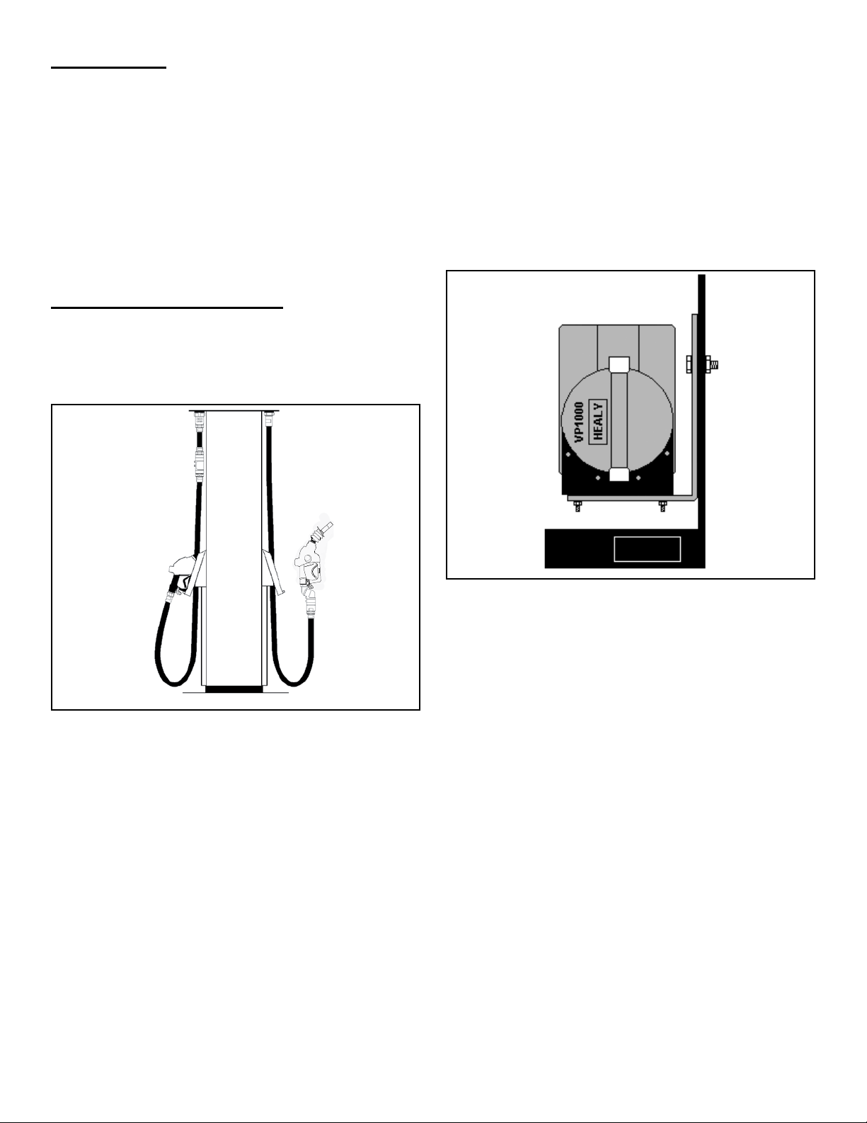
Description of Operation
The Healy Systems VP1000-220-IC Vacuum Pump
is typically mounted in the lower hydraulic area of a
dispenser or self-contained gasoline pump. It works as
a component of a complete Stage II system which also
includes Healy hanging hardware (Figure 1).
Vacuum Pump Features
• Operates at two speeds: Low Speed if one fueling point
has been activated, or High Speed if both fueling points
are activated simultaneously.
• Contains performance protection devices that will shut
off the vacuum pump and disable dispensing if the
vacuum pump is not operating properly.
• Contains internal control and operates as a ‘stand alone’
Vacuum pump.
• Contains low temperature activation circuits that turn the
vacuum pump on at slow speed when the temperature
drops below 40° F (4º C) to prevent freezing.
IN
Figure 1: Hanging Hardware
It is intended for use by either OEM dispenser / pump
manufactures or as an aftermarket retrot to make existing
equipment compatible with Healy Systems technology.
Specications: 1/8 Hp, 220 VAC input, 2 Amp AC
Note: All electrical and hydraulic plumbing ttings referred
to in these instructions must be UL “listed” or
“recognized”.
OUT
Figure 2: VP1000-220-IC Typical Mounting
Note: The VP1000-220-IC will increase the current draw
of the dispenser by 2 amps.
The preferred mounting position of the VP1000-220-IC
Vacuum Pump is with the vacuum pump inlet and electrical
connections facing upwards, towards the top of the
dispenser (see Figure 2 below). If other mounting positions
are desired because of mechanical constraints within
the dispenser, please contact FFS Technical Services at
1-800-984-6266.
4
Preparation
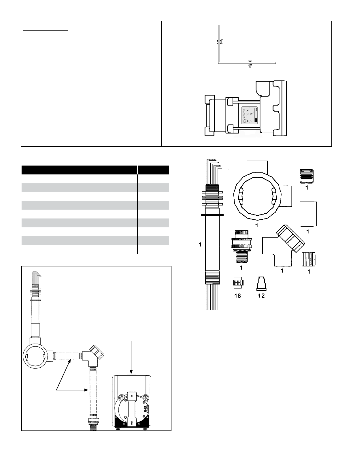
Parts List
This section illustrates the basic components needed
to retrot a VP1000-220-IC Vacuum Pump into any
new, replaced, retrotted, or reconditioned dispenser.
This system can be installed in any “Non-Vapor
or Vapor Ready” dispenser including dispensers
with existing “Balance” or “VacAssist” piping. Three
items are required for complete retrot installations:
VP1000-220-IC, Vapor kit, and Electrical kit. Other
supplies beyond these items may also be needed to
complete your installation (i.e. electrical nipples and,
possibly, additional vapor connections).
Assorted lengths of “UL Listed” electrical nipples as
well as pipe or electrical elbows and couplings will be
required to complete vacuum pump installation.
Figure 3: VP1000-220-IC Mounting Parts
Electrical Kit Z069E for 220VAC Applications
Part Quantity
Explosion Proof Junction Box 1
Capped 90° Elbow 1
1/2" Union 1
Potted Conduit Nipple 1
1/2" x 3/4" Reducing Bushing 1
3/4" Coupling 1
3/4" Close Nipple 1
Electrical Wire Nuts 12
Scotchlok
™
Wire Connectors 18
Mounting Bracket & Hardware
VP1000-220-IC Vacuum Pump
1/2" Conduit
supplied by the
Installing Contractor
Electrical Conduit
Connection to the
VP1000-220-IC
Vacuum Pump
Figure 4: Electrical Parts
Figure 5: Universal Electrical Kit Z069E
5
 Loading...