

Page 1

DC400 Dispensing Cutoff System
404-4 Controller
Installation Instructions
Franklin Fueling Systems • 3760 Marsh Rd. • Madison, WI 53718 USA
Tel: +1 608 838 8786 • 800 225 9787 • Fax: +1 608 838 6433 • www.franklinfueling.com
Page 2
Important Safety Messages
Franklin Fueling Systems (FFS) equipment is designed to be installed in association with volatile hydrocarbon liquids such
as gasoline and diesel fuel. Installing or working on this equipment means working in an environment in which these highly
ammable liquids may be present. Working in such a hazardous environment presents a risk of severe injury or death
if these instructions and standard industry practices are not followed. Read and follow all instructions thoroughly before
installing or working on this, or any other related, equipment.
As you read this guide, please be aware of the following symbols and their meanings:
Warning
This symbol identies a warning. A warning sign will appear in the text of this document when a potentially
hazardous situation may arise if the instructions that follow are not adhered to closely. A potentially hazardous
situation may involve the possibility of severe bodily harm or even death.
Caution
Warning
Warning
Warning
Warning
This is a caution symbol. A caution sign will appear in the text of this document when a potentially hazardous
environmental situation may arise if the instructions that follow are not adhered to closely. A potentially
hazardous environmental situation may involve the leakage of fuel from equipment that could severely harm
the environment.
Follow all applicable codes governing the installation and servicing of this product and the
entire system. Always lock out and tag electrical circuit breakers while installing or servicing this
equipment and any related equipment. A potentially lethal electrical shock hazard and the possibility
of an explosion or re from a spark can result if the electrical circuit breakers are accidentally
turned on during installation or servicing. Please refer to the Installation and Owner’s Manual for
this equipment, and the appropriate documentation for any other related equipment, for complete
installation and safety information.
Follow all federal, state and local laws governing the installation of this product and its associated
systems. When no other regulations apply, follow NFPA codes 30A and 70 from the National Fire
Protection Association. Failure to follow these codes could result in severe injury, death, serious
property damage and/or environmental contamination.
Always secure the work area from moving vehicles. The equipment in this manual is usually mounted
underground, so reduced visibility puts service personnel working on this equipment in danger from
moving vehicles entering the work area. To help eliminate these unsafe conditions, secure the area
by using a service truck to block access to the work environment, or by using any other reasonable
means available to ensure the safety of service personnel.
Use circuit breakers for multiple disconnect to turn off power and prevent feedback from other dispensers.
List of Parts
Description Part Number
QTY QuickON Wire connectors 210-0083
Controller 404-4
List of Tools
• Industry-standard, non-sparking tools
• Allen wrench, 19mm
• Conduit and ttings as required, must be UL
listed for use in Class I, Div 1 locations
Junction Box internal volume requirements per conductor:
Size of Conductor (AWG) Free space required for
each conductor (in3)
18 1.5
16 1.75
14 2.0
12 2.25
10 2.5
Determine volume of Junction box. This information may be on the
junction box itself usually expressed in cubic inches. If not, measure the
inside length, width, and depth of the box and multiply these numbers
together. This gives you the free volume of the junction box.
If the junction box is round measure the inside diameter and multiply this
number by itself. Multiply this number by 0.78 and record this answer.
Then measure the depth of the junction box and multiply it by the sum of
your rst answer. This gives the free volume of a cylindrical junction box.
Using the table above, subtract the cubic inches per each conductor
which originates outside the junction box and terminates or is spliced
within the junction box. Each conductor that passes through the junction
box without splice or termination shall be counted once. Refer to
National Electric Code 2011, article 314.16 (B).
2
Page 3
Product Description
The DC400 system uses a sump sensor to detect the
presence of liquid in the STP (Submersible Turbine Pump)
or dispenser sump. If liquid is detected, the system will
shut down power to the STP or dispenser.
The DC400 system consists of the 404-4 Controller and
either a 2-Wire or 3-Wire sensor. Follow these instructions
for installation of the 404-4 Controller. Franklin Fueling
Systems sensors approved for use with the DC400 system
come with their own installation instructions.
Specications:
Input line voltage: 90 – 250VAC 50/60 Hz
404-4 power consumption: 2W
Relay switch conguration: SPST
Relay switch contact rating: 12A continuous, 250VAC
maximum
Operating temperature: -20 to 60 degrees C
Hazardous location
Class I, Div 1, Group D
category:
Refer to Franklin Fueling Systems control drawing 000-1737
Installation for Dispenser Cutoff
Notice! Only qualied service
Warning
Warning
Note: Install this kit ONLY in a UL listed dispenser.
Note: If the is no junction box or open port on the junction
box, you cannot install this kit.
1. Shut off all power to the dispenser. Lock out and
tag the corresponding dispenser circuit breaker.
2. Open / remove the dispenser lower panel for
access to the dispenser hazardous area. Inspect
the hazardous area to locate the dispenser
explosion proof power entry junction box. The 4044 controller will be wired into the dispenser via a
spare conduit hub located on the dispenser power
entry junction box.
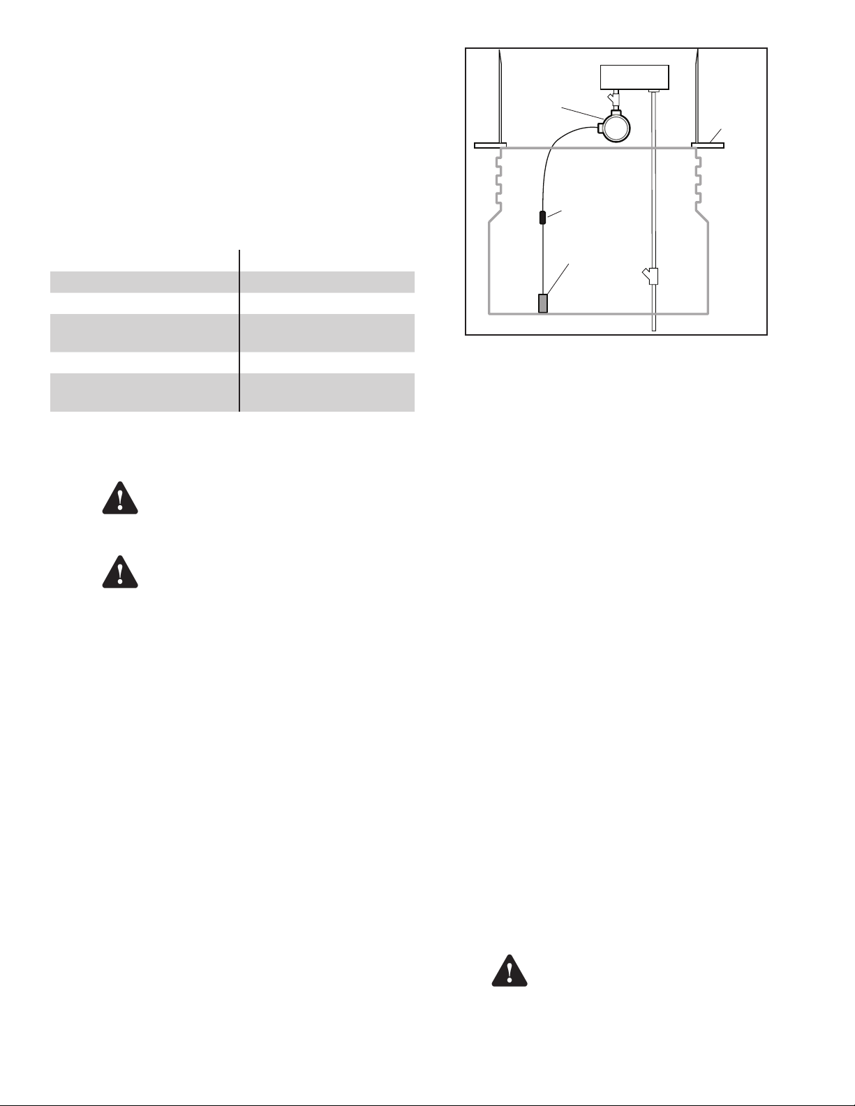
3. Determine where to best locate the 404-4
controller and how best to plumb conduit from
the dispenser spare conduit hub to the 404-4
controller. The 404-4 controller must be located
so that regular servicing of the dispenser (such as
changing of fuel lters) will not be impeded. The
404-4 controller can be located in the dispenser
hazardous area or suspended down below the
dispenser in the dispenser sump as room dictates.
Refer to gure 1.
technicians experienced with petroleum
dispensing and pumping systems
should install the DC400 system.
Notice! Do NOT exceed the 12A
(continuous), 250VAC relay contact
rating of this controller. Relay contacts
are not fused.
Dispenser
404-4
Controller
Cable Connection
2-Wire or
3-Wire sensor
Figure 1: Typical System Installation in a Dispenser Sump
Note:
Because each dispenser installation is unique it is
Junction Box
EYS
Dispenser
Base
Dispenser
Sump
EYS
impossible to provide a “one size ts all” conduit
tting kit. Necessary explosion-proof conduit and
conduit ttings must be determined and supplied by
the installer. The 404-4 controller conduit size is 3/4”
NPT. Simple ttings such as elbows, sweeps, unions,
and nipples should be used and must be UL listed and
suitable for use in Class I, Div 1, Group D locations.
4. Open the dispenser power entry junction box
cover and retain hardware for later use. Remove
spare junction box plug and plumb explosion-proof
conduit from the spare conduit entry hub to the
404-4 controller power port (the port with 6 wires
protruding). Thread the 6 wires coming out of the
power port of the 404-4 controller through the
conduit to the dispenser power entry junction box.
Important! Be sure installation of conduit, ttings and
wiring is in accordance with local, State and
National electrical codes. A conduit seal must be
installed between the dispenser J-box and the
controller. The conduit seal must be within 18" of
the dispenser J-box and the 404-4 controller. Refer
to NEC NFPA 70, article 501.15 (A) (3), 2011. Make
sure the dispenser power entry junction box has
enough spare room to accommodate the additional
404-4 controller wires (see the table on page 2).
Important! When tightening the conduit to the 404-4
controller, use a wrench on the conduit ttings and
not the 404-4 controller body.
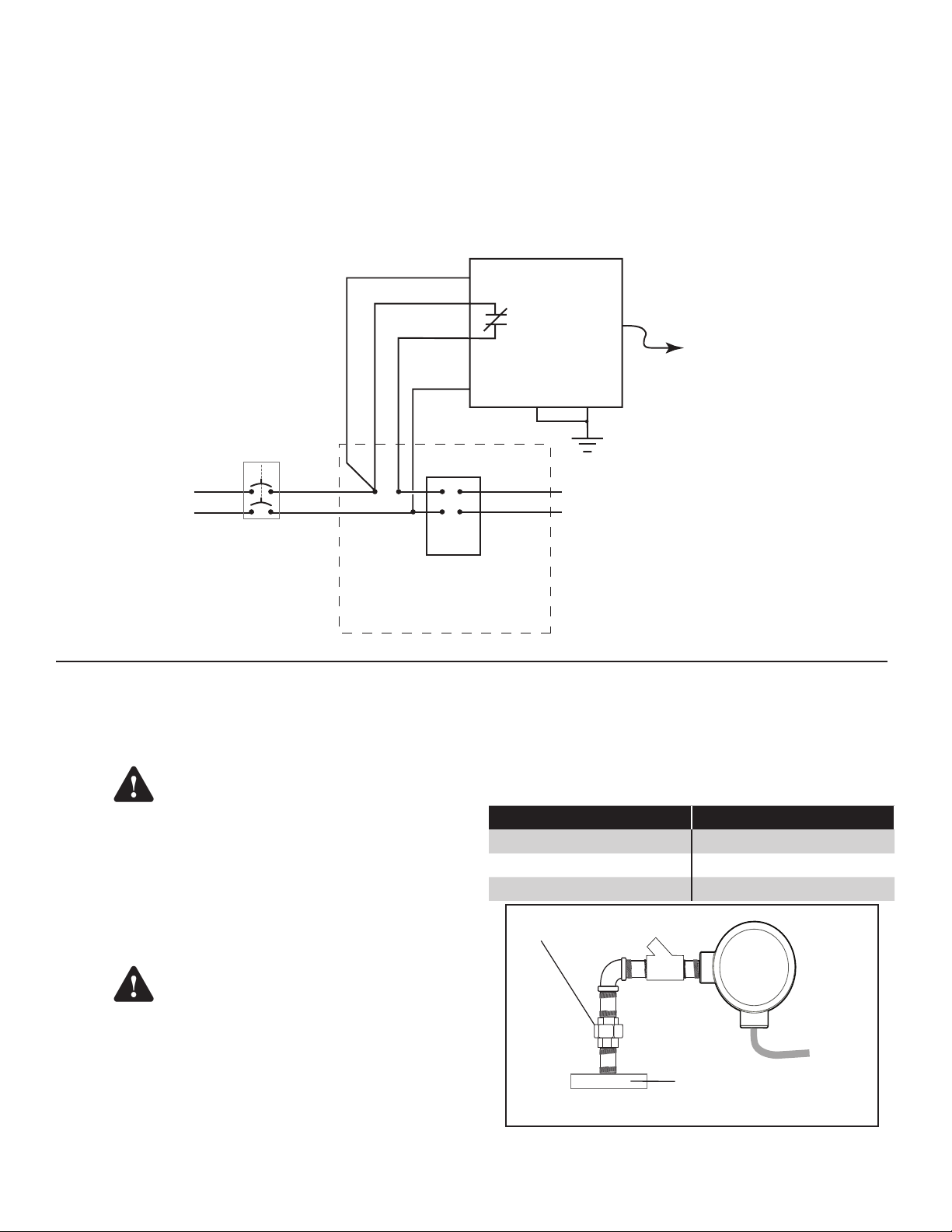
5. Wire the 404-4 power wiring per the schematic
that matches your dispenser listed in Figures
7 - 14. Contact your dispenser manufacturer for a
wiring diagram if you are unsure of the dispenser
input power wiring.
Make sure to connect both ground
Warning
wires and verify they are connected
to earth ground. Failure to do so may
result in a re or explosion hazard in
case of a fault condition.
3
Page 4
404-4
Controller
To Sensor
Connection
Explosion Proof Union
STP Junction Box Cover
NOTE: Use reducer to connect ¾" conduit
to ½" cover opening.
EYS
6. Connect the sensor wire cable coming from the 404-4 controller to the appropriate Franklin Fueling Systems
sensor. Refer to the sensor’s installation instructions for installation, wiring and testing of the sensor.
The sensor must be installed in accordance with the sensor’s control drawing and with Franklin Fueling System’s control
drawing 000-1737.
7. Double check all dispenser & controller power wiring to be sure it is correct then replace the dispenser power
entry junction box cover. Secure the cover with all of the bolts previously retained.
8. Turn the dispenser power back on. The dispenser should operate normally.
9. Replace and secure lower dispenser door(s).
10. Test the DC400 dispenser cutoff by submerging the sensor in water. The dispenser should shut off and remain off
as long as the sensor is submerged.
BLK
ORG/BLK
ORG
WHT
Dispenser
Breaker
404-4 Controller
12A, 240VAC
GRN
To Dispenser
Inputs
Sensor
GG
GRN/YEL
To Dispenser Earth Ground terminal
Installation for Submersible Pump Cutoff
Notice! Only qualied service technicians experienced
with petroleum dispensing and pumping systems
should install the DC400 system.
Warning
Notice! Do not exceed the 12 A (continuous), 250 VAC relay
contact rating of this controller. Relay contacts are not
fused. This controller is suitable for most submersible
pumps rated up to 2 hp @ 250 VAC and 1½ hp @
120 VAC. provided the maximum pump motor
service factor amperage is 12A or less. Contact the
submersible pump manufacturer if in doubt.
Warning
1. Shut off power to the STP. Lock out and tag the
2. In pump cutoff installations the 404-4 controller
4
Refer to MFG
wiring schematic
for terminal block /
wire connections
Dispenser Main Junction Box
Figure 2: Power Wiring Schematic for Controller Dispenser Connection
This controller is NOT for use with
3-phase pumps or Variable Frequency
Drive pump installations.
Remove power to avoid possible
electrocution or ignition of explosive
gasoline vapors.
corresponding STP circuit breaker.
will be connected directly to the integral electrical
junction box on the STP via rigid explosion proof
conduit. Since STP sump installations can vary,
the installer will need to determine where best to
place the controller in the sump and then procure
the necessary conduit and ttings.
A typical means of connecting the controller to
an STP via an explosion proof union is shown in
Figure 3. All ttings must be UL listed and suitable
for use in a Class I, Div 1, Group D environment.
If the STP junction box does not have a removable plug or
opening, installation adapters are available as listed below.
Installed STP Installation Adapter
FE Petro TS-FE
Red Jacket TS-RJ
Red Jacket Quantum TS-RJQ
Figure 3: Typical Connection to STP
Page 5

3. Remove the STP junction box cover / plug. Make
Orange / Black
sure the STP junction box has enough room to
accommodate the additional 404-4 controller wires
(see the table on page 2). Thread the six 4044 power wires from the power port through the
conduit ttings and plumb the conduit ttings to
the 404-4 controller. Connect the controller power
wires to the STP wiring as shown in gure 4.
Make sure to connect both ground
Warning
4.
Join the controller conduit to the STP junction
box cover and replace the cover on the STP
and securely tighten. A union will be required to
do this, (see Figure 3). A conduit seal must be
installed between the electrical junction box and the
controller. The conduit seal must be within 18” of
the electrical junction box and the 404-4 controller.
Multiple conduit seals may be required for some
installations, depending upon the ditance between
the electrical junction box and the 404-4 controller.
Refer to NEC NFPA 70, article 501.15 (A) (3), 2011.
5. Connect the sensor wire cable coming from
the 404-4 controller to the appropriate Franklin
Fueling Systems sensor. Reference the sensors
installation instructions for installation, wiring and
testing of the sensor.
6. Turn the STP circuit breaker back on and test
the DC400 system for proper operation. With the
sensor dry, the STP should operate normally.
wires and verify they are connected
to earth ground. Failure to do so may
result in a re or explosion hazard in
case of a fault condition.
7. Next, test the DC400 pump cutoff by submerging
the sensor in water. The pump should shut off and
remain off as long as the sensor is submerged.
(Note: if the pump is controlled and monitored by
an external pump controller or tank gauge, this
device may need to be reset when the sensor is
removed from the water).
STP Electrical
Junction Box
STP Sump
404-4 Controller
2-Wire or
3-Wire Sensor
Figure 5: Typical STP Sump Installation
EYS
L1
From pump
control relay
or contactor
(220 VAC)
L2
Black
Controller
/Relay
White
404-4 Controller
Figure 4: Power Wiring Schematic for STP Connection
N.C.
(When Dry)
* Safety Ground
Orange
Green
STP
* Yellow/Green
Black
5
Page 6

Installation for Alarm Wiring
Important! For all applications, do not exceed the relay
contact rating of 250VAC, 12A.
The relay contacts (Orange / Black and Orange wires)
on the 404-4 controller are normally closed dry contacts
(when power to the controller is applied) that will open
when liquid is detected. This enables the DC400 to be
wired for various alarm notication and monitoring.
Figure 6 shows an example of alarm wiring for applications
that do not require positive shutdown but simply some sort
of visual and / or audible notication. In this example the
alarm light illuminates when the DC400 detects liquid.
404-4 Controller
Contacts
120 VAC
Testing
Test the function of the system according to applicable
codes. Test immediately after installation, and at least
annually to verify proper system operation.
Troubleshooting
If the controller relay repeatedly cycles or oscillates
when the sensor is tripped, it is likely that the controller is
switching its own power. Check the wiring diagram and
conrm that the controller is wired properly. Make sure that
the orange / black, red and black wires are tied to power
from the breaker and the orange wire feeds the dispenser.
If problems continue, please contact FFS Technical
Support at 800-984-6266.
N.C.
Orange / Black
120 VAC
Neutral
Figure 6: Wiring Example for Non-Positive Shutdown
Orange
External
120 VAC
Relay Coil
120 VAC
Alarm Pilot Light
N.C.
Neutral
6
Page 7

Dispenser-Specic Wiring
404-4 Controller
12A, 240VAC
H
120-240VAC
N
GRN
Dispenser
Breaker
ORG/BLK
ORG
BLK
WHT
1
2
3
4
5
6
7
8
9
10
11
12
W-V
Main Junction Box
Figure 7: 404-4 Wired to a 120V Dresser-Wayne Vista 3 Series Dispenser
Sensor
GG
GRN/YEL
Sensor
404-4 Controller
12A, 240VAC
120-240VAC
GG
GRN/YELGRN
H
N
ORG/BLK
ORG
BLK
WHT
Junction Box
W-BN
W-R
BK
W-BK
Line
N
Dispenser Control
Power
Figure 8: 404-4 Wired to a Dresser Wayne Ovation Dispenser
W
BNVV
Y
7
Page 8

Dispenser
Breaker
404-4 Controller
ORG/BLK
12A, 240VAC
ORG
BLK
H
120-240VAC
WHT
Line
N
GRN
Neutral
Earth Ground
Main Junction Box
Figure 9: 404-4 Wired to a Gilbarco Eclipse Dispenser
GG
GRN/YEL
Sensor
Line
Neutral
Earth Ground
Dispenser
Breaker
Field Conduit
BLK
WHT
GRN/YEL
Main Junction Box
ORG/BLK
ORG
WHT
BLK
H
N
A-10
404-4 Controller
12A, 240VAC
120-240VAC
GRN
A-2
A-13
Sensor
GG
GRN/YEL
Main Conduit
BLK
WHT
GRN/YEL
Electronics Cabinet
(CD Module)
Figure 10: 404-4 Wired to a Gilbarco Encore 300 or 500 Dispenser
8
Page 9

Dispenser
Breaker
Main Junction Box
BLK - ACH
BLK
ORG/BLK
ORG
WHT
BLK - ACH
404-4 Controller
12A, 240VAC
120-240VAC
GRN
Sensor
GG
GRN/YEL
Dispenser
Breaker
WHT - ACC
WHT - ACC
Figure 11: 404-4 Wired to a Tokheim 262 or 262A Dispenser
Dispenser Junction Box
BLK
ORG/BLK
ORG
WHT
UDC - ACH
9
120-240VAC
404-4 Controller
12A, 240VAC
GRN
Sensor
GG
GRN/YEL
UDC - ACC
10
Figure 12: 404-4 Wired to a Tokheim Premier Dispenser
9
Page 10

Page intentionally blank
10
Page 11

Page intentionally blank
11
Page 12

©2011 000-0316 Rev A
 Loading...