

Page 1
Colibri System Board
Field Replacement Instructions
Tools Needed
• ¼ Inch nut driver
• #2 Phillips screwdriver.
Backup Settings
If replacing a board that can still communicate, connect to
it and download setup, registration le and database.
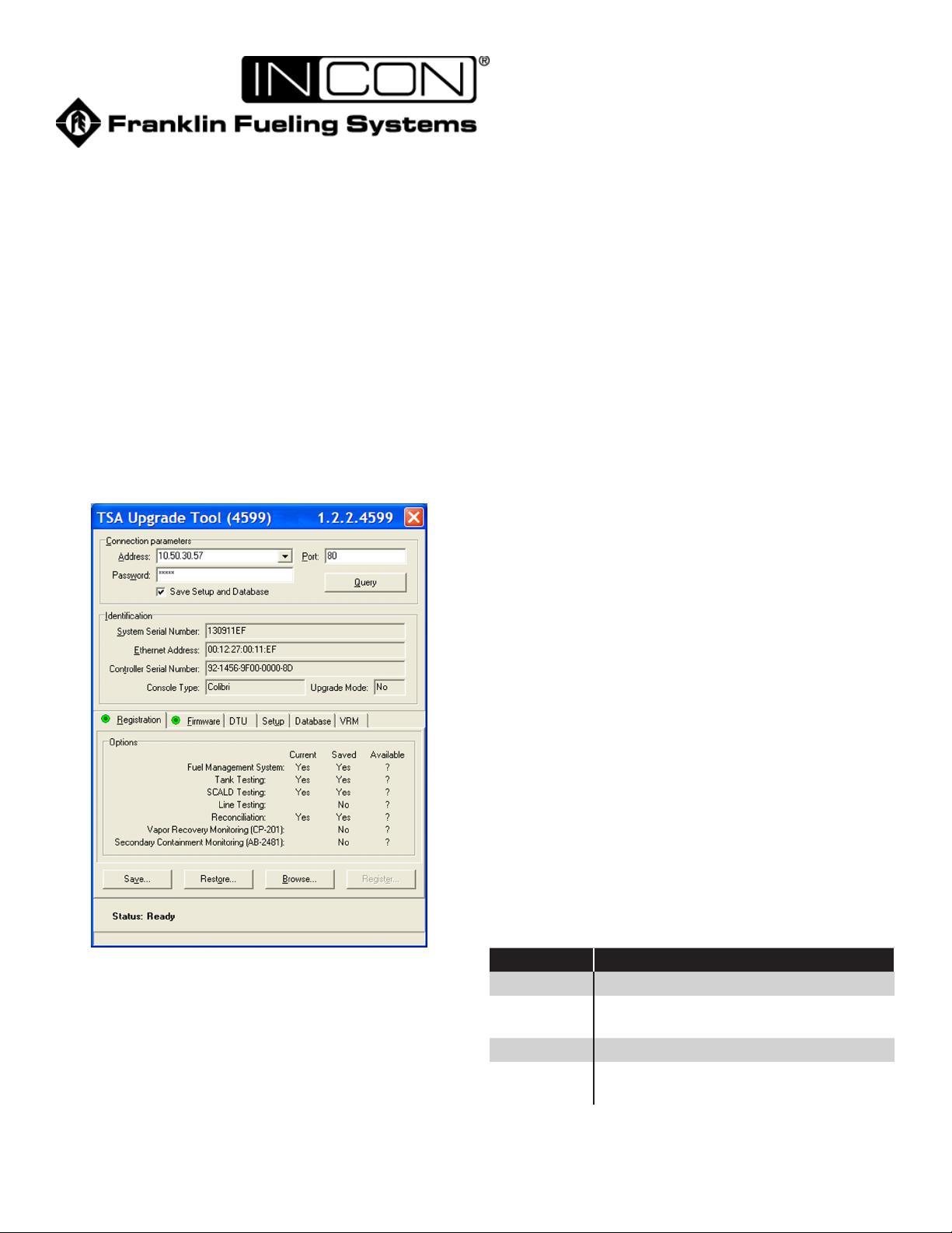
To backup the data, use the TSA Upgrade tool. Refer
to INCON document 000-0075 for information about
downloading and using the upgrade tool. Individually
select the tabs Registration, Setup and Database and in
each case click Save.
5. Remove the two screws on the right hand side of
the board (4 and 5 in Figure 2) and set them aside
with the Intrinsically Safe shield and the display
ground strap.
6.
Remove the standoffs from the top right and bottom
left corners of the board (3 and 4 in Figure 2).
7. Grasp the board and gently pull out from the top.
Once the top portion is an inch or so from the
enclosure gently lift the board up and out of the
enclosure.
Before placing the replacement board in the enclosure,
rst remove the two lock nuts from the left hand side of the
power block/brick (1 and 2 in Figure 2) being careful that
the screws do not drop out. Use the two nuts to secure the
two screws on the unit that was removed. There will also
be a locknut under the standoff in location 4.
The replacement board that is being installed will be one of
two types:
• CL-MBXX Spare controller module, Fuel Management
System Application only, no software options
• CL-MBXX Replacement controller module, factory
programmed with the systems required options
If the system is having the board replaced with a spare
module, the board may need to be upgraded to regain
either SCALD or TRAC software options. This is only if the
original system had these software options included.
Figure 1: Upgrade Tool Screen
Removing Existing System Board
1. Remove electrical power from unit at the breaker.
2. Remove the front cover from the unit.
3. Disconnect the plugs from the Power, Relay and
Probe receptacles and any communication cables
or USB sticks attached to communication ports.
4. Loosen the two screws on the left hand side of the
power brick (1 and 2 in Figure 2). Do not pull the
screws out.
1 of 2
The TSA Upgrade tool can be used to upgrade the CLMBXX. For assistance with upgrades, contact the FFS
Technical Support Team.
If the CL-MBXX is ordered for the correct serial number
of the system, the board will have the necessary software
options installed. This will be a “plug and play” board
replacement.
Part # Description
CL-MB CL6 Replacement mainboard, no display
CL-MB/R CL6 Replacement mainboard, no display
with required options
CL-MBWD CL6 Replacement mainboard with display
CL-MBWD/R CL6 Replacement mainboard with display
and required options
Page 2
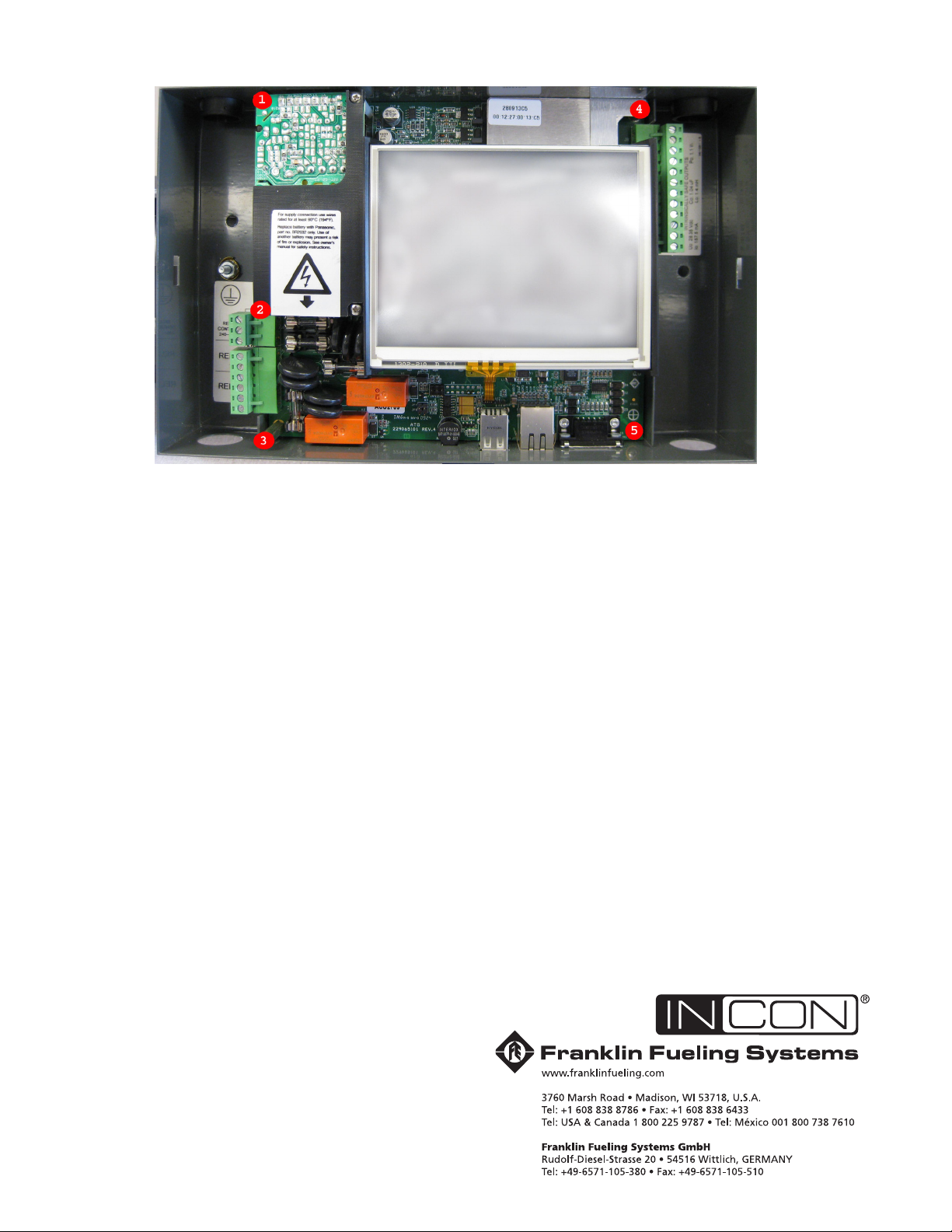
Figure 2: System Board Fastener Locations
Install New System Board
1. Gently slide the board into the enclosure so that
the communication ports are aligned with the
proper holes in the enclosure. Gently push the
board down so that the communication ports
slide into the holes. Then push the board into the
enclosure so that it is fully seated.
2. Tighten the two screws on the left hand side of the
power supply (1 and 2 on Figure 2).
3. Install the long standoff in the bottom left hand
corner and the short standoff in the top right hand
corner
(3 and 4 in Figure 2)
4. Install one screw with lock washer in the bottom
right hand corner (5 in Figure 2).
5. Place the intrinsically safe shield and the ground
strap over the potted area so that the hole is
aligned with the hole in the short standoff and
fasten with the remaining screw with lock washer
(4 in Figure 2). The tab of the ground strap must
be inserted between the display and the display
support during reassembly. Ensure the tab of the
ground strap is pushed into the crook of the display
mount and not in contact with the glass of the
display.
.
6. Connect power, relay and probe plugs to the proper
receptacles.
7. Connect any communication cables or USB sticks
in use.
8. Apply power to the unit.
9. Upload any saved set-up, registration or database
les as needed (TSA upgrade tool: select the tab
and then click restore).
Note;
Units will be furnished with the IS shield and ground
strap installed.
©2010 FFS 000-0309 Rev A
 Loading...