

Page 1
Colibri
Tank Monitoring System
CL6 Series
Set-Up and Operator’s Guide
Franklin Fueling Systems • 3760 Marsh Rd. • Madison, WI 53718 USA
Tel: +1 608 838 8786 • 800 225 9787 • Fax: +1 608 838 6433 • www.franklinfueling.com
Page 2
Important Safety Messages
This equipment is installed close to gasoline and diesel fuel. Working in such a hazardous environment presents a
risk of severe injury or death if these instructions and standard industry practices are not followed. Read and follow all
instructions thoroughly before installing or working on this, or any other related, equipment.
Be aware of the following symbols and their meanings:
A warning sign will appear in the text of this document when a potentially hazardous situation may arise if the
Warning
Caution
Danger
instructions that follow are not adhered to closely. A potentially hazardous situation may involve the possibility
of severe bodily harm or even death.
A caution sign will appear in the text of this document when a potentially hazardous environmental situation
may arise if the instructions that follow are not adhered to closely. A potentially hazardous environmental
situation may involve the leakage of fuel from equipment that could severely harm the environment.
An electrical danger sign will appear in the text of this document when a potentially hazardous situation
involving large amounts of electricity may arise if the instructions that follow are not adhered to closely. A
potentially hazardous situation may involve the possibility of electrocution, severe bodily harm, or even death.
Alarms and warnings alert you with specic details when a problem occurs so you can take corrective
action. System hardware failure warnings and tank leak alarms can be programmed to do many things.
The events that require programming are denoted by a (p) below:
- cause the red Alarm light or yellow Warning light to ash (standard)
- activate / sound the console annunciator alarm horn (p)
- activate internal output relays for external alarm devices (p)
- print alarm reports automatically via attached USB printer (USB - HP compatible printer) (p)
- send alarm and test reports to a specied email address (p)
Warning
Warning
Warning
Warning
Warning
Warning
Follow all applicable codes governing the installation and servicing of this product and the
entire system. Always lock out and tag electrical circuit breakers while installing or servicing
this equipment and any related equipment. A potentially lethal electrical shock hazard and the
possibility of an explosion or re from a spark can result if the electrical circuit breakers are
accidentally turned on during installation or servicing. Please refer to the Installation and Owner’s
Manual for this equipment, and the appropriate documentation for any other related equipment, for
complete installation and safety information.
Follow all federal, state and local laws governing the installation of this product and its associated
systems. When no other regulations apply, follow NFPA codes 30, 30A and 70 from the National Fire
Protection Association. Failure to follow these codes could result in severe injury, death, serious
property damage and/or environmental contamination.
Always secure the work area from moving vehicles. The equipment in this manual is usually
mounted underground, so reduced visibility puts service personnel working on this equipment in
danger from moving vehicles entering the work area. To help eliminate these unsafe conditions,
secure the area by using a service truck to block access to the work environment, or by using any
other reasonable means available to ensure the safety of service personnel.
When the Fuel Management System is used to monitor tanks containing gasoline or other
ammable substances, you may create an explosion hazard if you do not follow the requirements in
this manual carefully.
All wiring must enter the console’s enclosure through the designated knockouts. An explosion
hazard may result if other openings are used.
You must run wiring from probes to the Fuel Management System console in conduits which are
separate from all other wiring. Failure to do so will create an explosion hazard.
2
Page 3

Contents
Important Safety Messages ............................................................................................2
Basic Console Operation ................................................................................................3
LCD Layout ............................................................................................................................. 3
Set up Preferences ..........................................................................................................6
Set up Conguration .......................................................................................................6
Entering Setup .................................................................................................................8
System ID ...............................................................................................................................8
System Conguration .............................................................................................................8
Probe Modules ........................................................................................................................8
Relay Modules ........................................................................................................................ 8
Dispenser Interface .................................................................................................................9
Setup-Fuel Management System ................................................................................. 11
Static Tank Testing ................................................................................................................ 12
Tanks ....................................................................................................................................12
Tank# Probe ................................................................................................................................ 13
Tank# Limits ................................................................................................................................ 13
Special tanks ........................................................................................................................13
Manifolds ..............................................................................................................................14
Products ................................................................................................................................14
Grades .................................................................................................................................. 14
Reconciliation .......................................................................................................................14
Autocalibration ...................................................................................................................... 14
E-mail Setup ...................................................................................................................15
System Sentinel AnyWare ............................................................................................15
Rules ...............................................................................................................................16
List of Default Rule Entries ................................................................................................... 16
Operation ........................................................................................................................17
Check Inventory .................................................................................................................... 17
Check Deliveries ................................................................................................................... 17
Alarms ...................................................................................................................................18
Print Reports ......................................................................................................................... 18
Web Browser Interface ..................................................................................................19
Connecting to the Console ...................................................................................................19
Web Interface Available Pages ............................................................................................. 21
Appendix A: List of Alarms ...........................................................................................22
Appendix B: Standard Tank Table ............................................................................... 25
Appendix C: Compatible Printers ................................................................................ 27
Appendix D - Standard Products Table ....................................................................... 27
Appendix E - Typical Tank Leak Test Times ................................................................27
Appendix F - Using the Console’s Autocalibration Feature ...................................... 28
3
Page 4
Basic Console Operation
The console can be operated through the LCD touch screen or the Web Browser Interface via a Personal Computer.
Refer to to page 16 for Web Browser Interface setup.
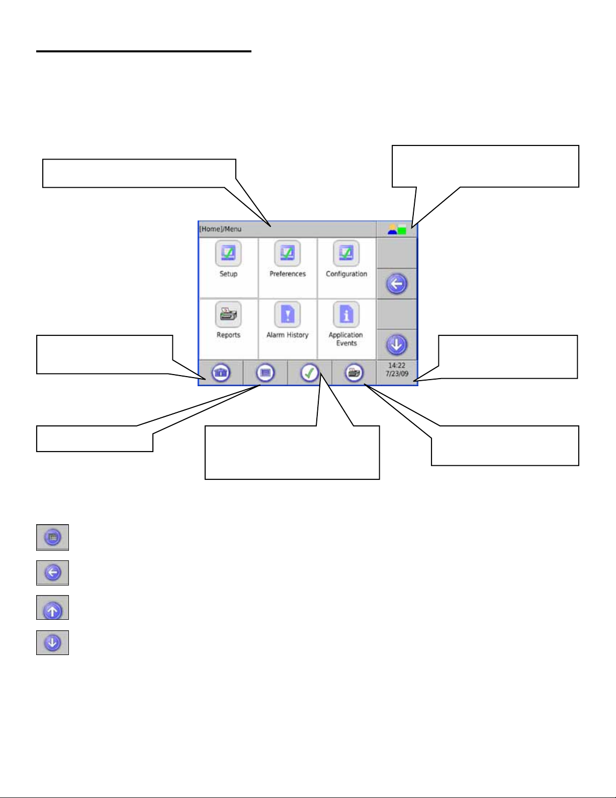
LCD Layout
The LCD interface allows the user to enter on-screen information.
User Role – Displays and allows
Path Bar – Shows the path / description
of information displayed.
changing the access level of the
current user
Home – Goes to the home
summary screen.
Main Menu – Access the
Application Menu.
Status:
ü = No Alarms.
! = Alarm. For alarms: press this to
go to the alarms page.
Date/Time – Press this to
change Time / Date settings.
Print Report – Pressing this
button will take you to a menu
of reports.
Navigation Buttons
The navigation buttons are on the right side of the LCD touch screen. These change depending upon the application.
FMS: FMS Function Menu
Back: Reverts to the previous screen.
Scroll Up: Indicates that more menu options are available above current view.
Scroll Down: Indicates that more menu options are available below current view.
4
Page 5
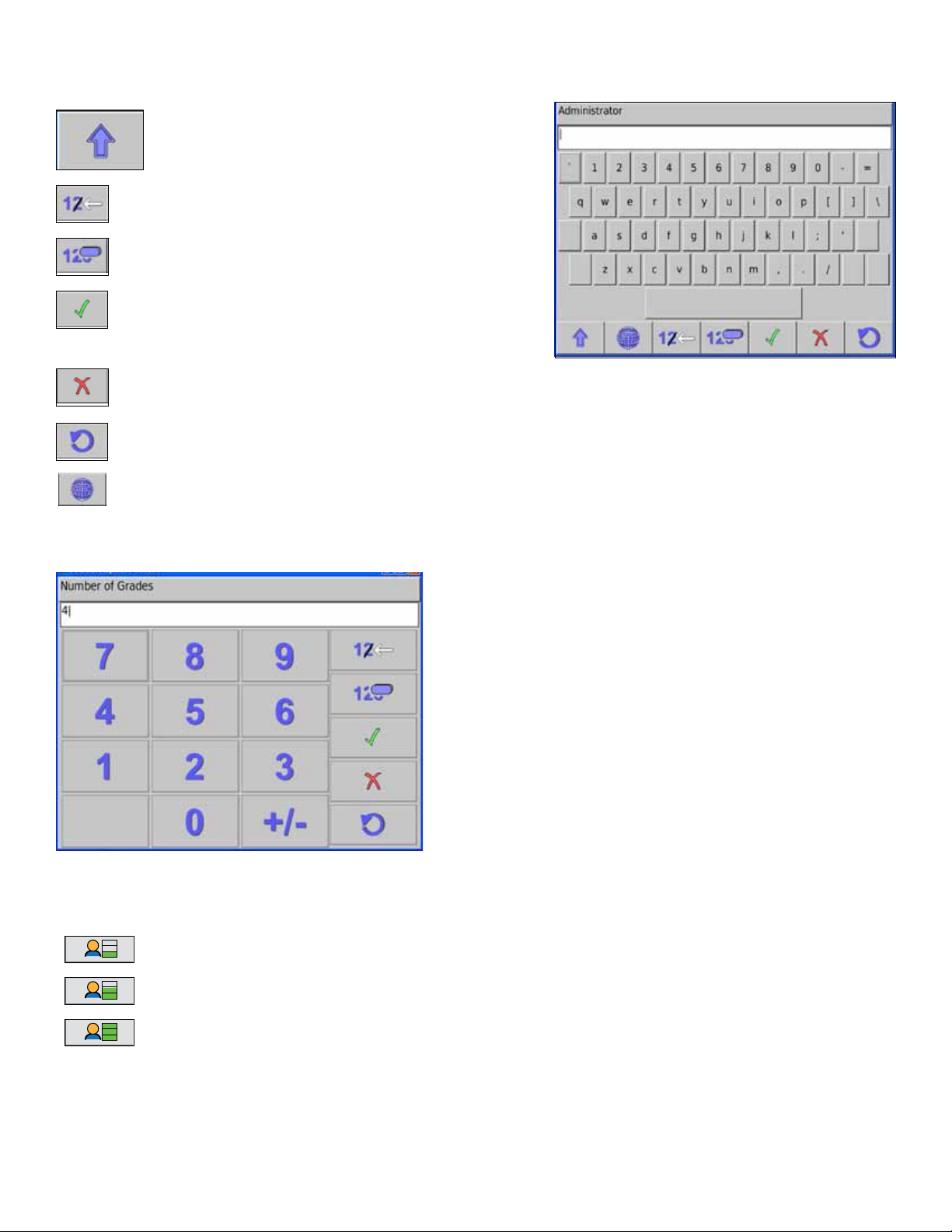
Data Entry
If you are prompted to enter information, a keypad and edit buttons will be displayed.
Character Selection: Selects between upper case
letters, lower case letters and numerals.
Backspace: Deletes the previous character.
Clear: Deletes data from the entry line.
Enter: Accepts the choice.
Cancel: Returns to the application and no changes will be made to console settings.
Restore Default: This will restore the original settings programmed into the console.
Alternate Characters: Shows accented characters
Number Entry
A screen like that below is used when number information is needed.
Security Access Control
Guest Monitor system status
User Perform system control.
Administrator Modify system setup, plus all
functions listed above
Note: For increased security, it is strongly suggested to change the default passwords (see page 6).
5
Page 6
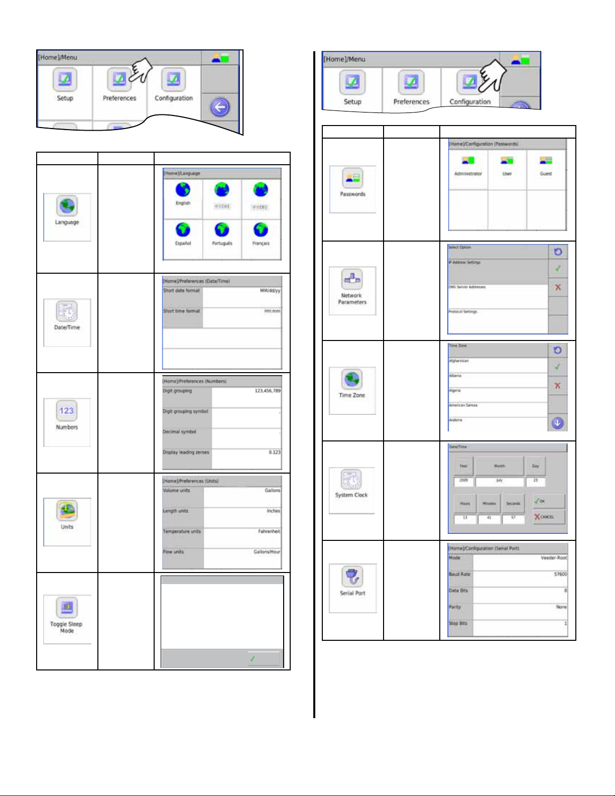
Set up Preferences
Set up Conguration
Display Description Values
Choose
language
for console
menus.
Choose date
and time
display format
Choose
format of
numbers
Display Description Values
Choose
passwords for
access
Set Network
Parameters
Choose
location for
correct time
zone
Set system
time and date
Choose units
of measure
Enables
blank screen
saver
Notification
Sleep Mode is now Enabled
OK
Set Serial
Port
Parameters
6
Page 7
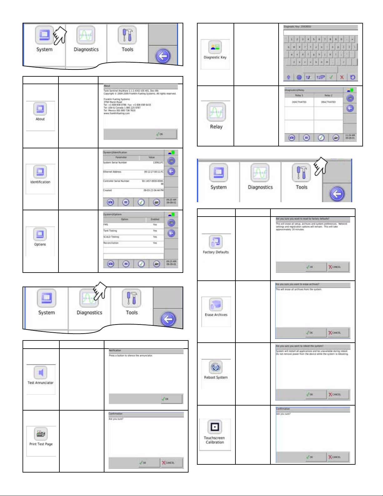
Display Description Values
Allows technicians
access to
diagnostic
functions*
Lists detail
about the
Console
Lists System
Parameters
Lists options
enabled
View relay state
and test operation
(read screen
caution notice)!
* Call FFS Tech Support for the password
Display Description Values
Restore
factory default
settings
Display Description Values
To Silence the
annunciator
To print or e-mail
a test page
Will erase all
archived data
Will reboot
system
Re-calibrates
screen
7
Page 8
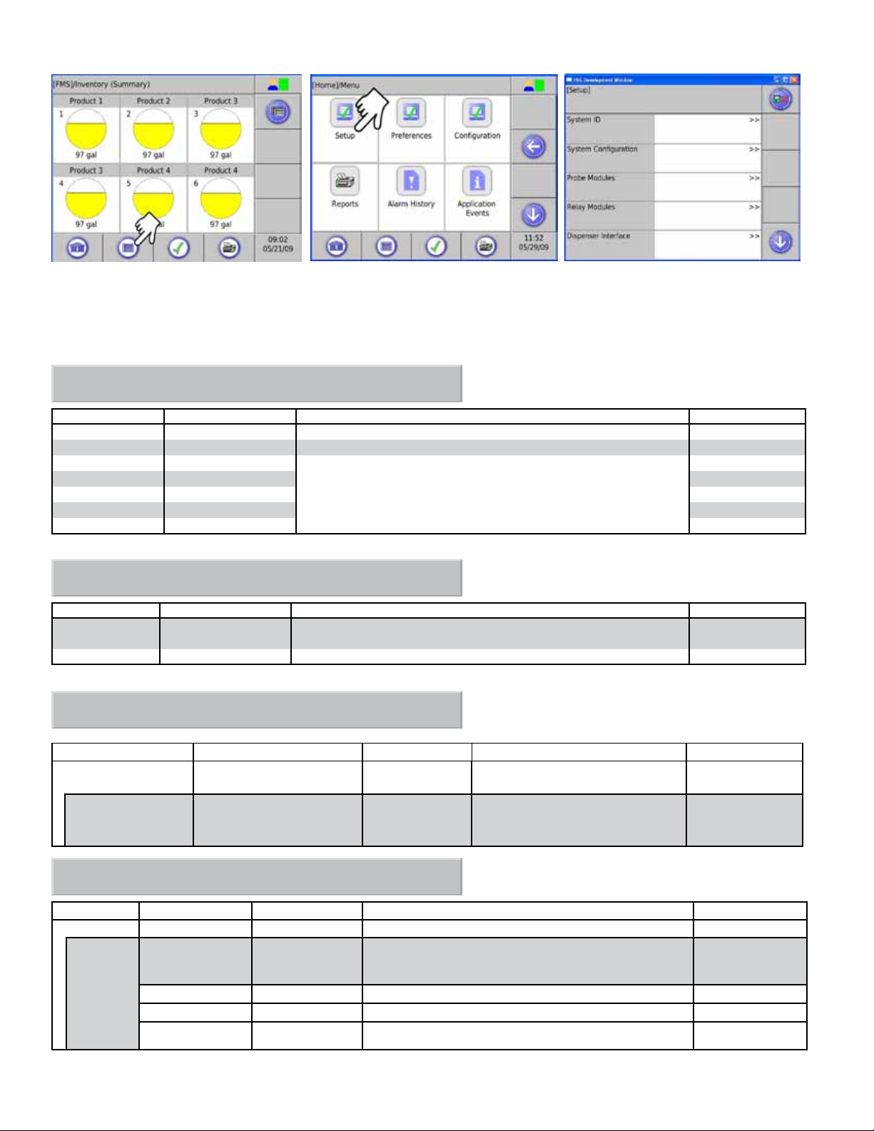
Entering Setup
Always enter information starting from the top of the menu. Later menus use this information.
Note that the tables are formatted to correspond to the Web Browser Interface. Information shown is also valid for the
LCD touch screen.
[Setup] / System ID
Parameter Name Parameter Value Description Max Characters
Site Name (Site Name) Name of site. 40
Web UI URL (http://localhost/tsa) URL address of site. 40
ID Line 1 (blank)
ID Line 2 (blank) 40
ID Line 3 (blank) 40
ID Line 4 (blank) 40
ID Line 5 (blank) 40
These lines should contain the physical address of the site. This
information is used in reports and to identify site properties when
using Web User Interface.
40
[Setup] / System Configuration
Parameter Name Parameter Value Description Value
Technical Support
Key
Enable Log Files (No) Enables the logging option. Yes/No
(0) Enter the appropriate key number. #
Note: The System Conguration entries are for use by Franklin Fueling Systems for diagnostic purposes.
[Setup] / Probe Modules
Parameter Name Parameter Value Description Value
Module # Channels (0)
Channel # Name (Probe 1) Given Name of Probe. abc#
Number of channels in use per
module.
1-6
(30 characters
maximum)
[Setup] / Relay Modules
Parameter Name Parameter Value Description Value
Module # Channels (2) Number of channels in use per module.
Channel # Name (Relay 1) Given name of the channel. abc#
Enabled (Yes) Yes if the channel is in use.
Polarity (Normal) Allows the polarity to be inverted.
Physically Wired As (Normally Open) How the relay is wired internally. NO, NC
1 or 2
(30 characters
maximum)
Yes / No
Normal, Invert
8
Page 9
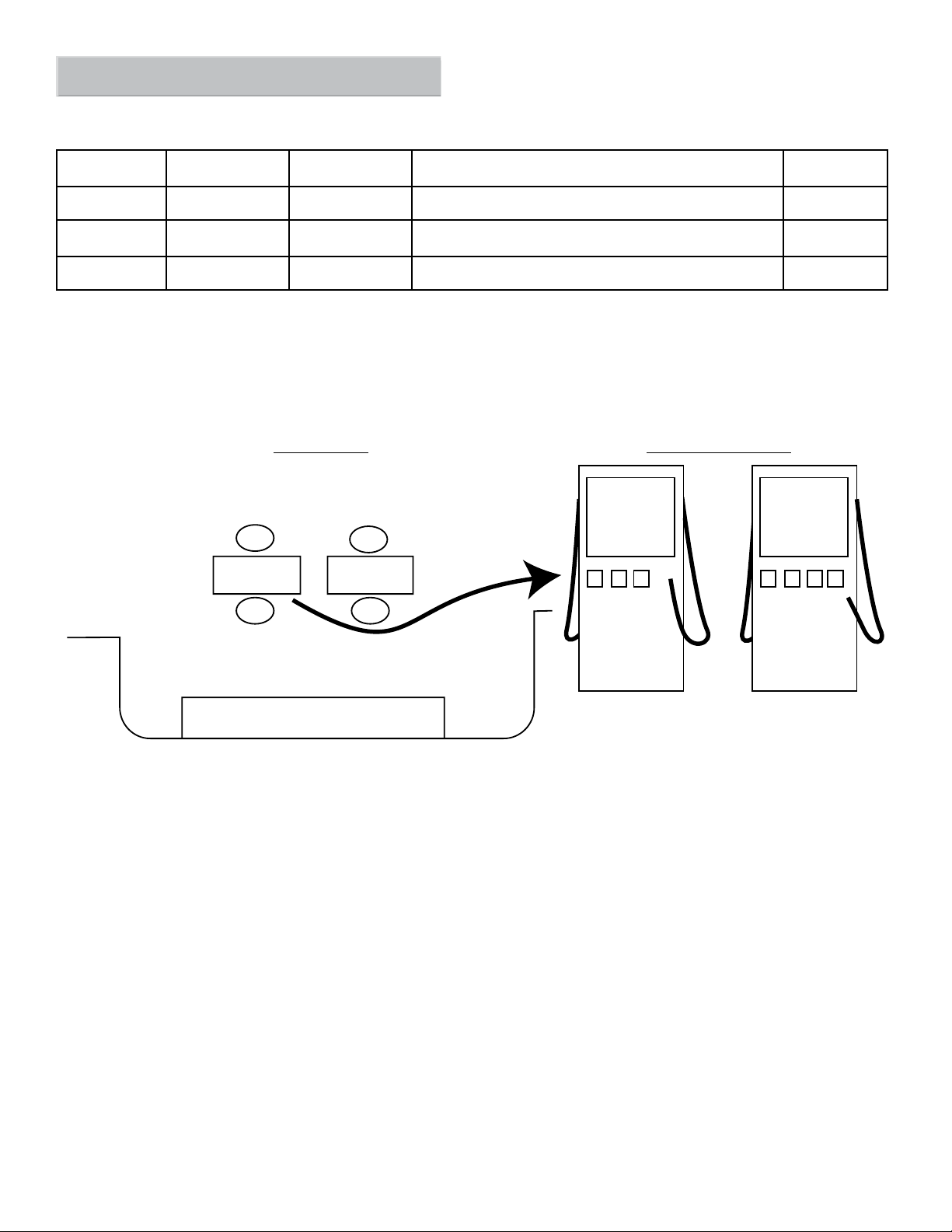
[Setup] / Dispenser Interface
Note: The Dispenser Interface allows the console to read dispensing information and requires the TS-TRAC option.
Dispenser information is sent through the Serial Port.
Parameter
Name
Grades Number of grades (0)
Fueling Points Number of fueling
Hoses Number of hoses (0) The number of grades available at a specic fueling point
Parameter Name Parameter Value Description Max Value
The number and name of products used at the site.
(0)
points
Anywhere on site where a vehicle can get fueled.
Dispenser Interface: Example of site set-up
There are 4 grades in this example:
• Unleaded
• Mid-grade
• Premium
• Diesel
Site Top View Dispenser Detail View
Dispenser 1 Dispenser 2
FP2
Dispenser 1 Dispenser 2
FP1
FP4
FP3
U M P U M P D
U = Unleaded
M = Mid-Grade
P = Premiuml
(0-32)
(0-32)
(0-8)
U = Unleaded
M = Mid-Grade
P = Premium
D = Diesel
FP = Fueling Point
There are 3
grades available
at Fueling Points
1 and 2. Number
of hoses = 3
There are 4
grades available
at Fueling Points
3 and 4. Number
of hoses = 4
To Setup Dispensing Information:
1. Connect the RS232 serial cable from the distribution box (D-box) to the RS232 port on the Colibri.
2. Verify that the RS232 Communication port settings on the console match the D-box communication settings.
Refer to Page 6 of this manual for Serial Port Setup options.
3. On the Colibri console, enter the number of grades. For this example (page 10), there are 4 grades.
9
Page 10
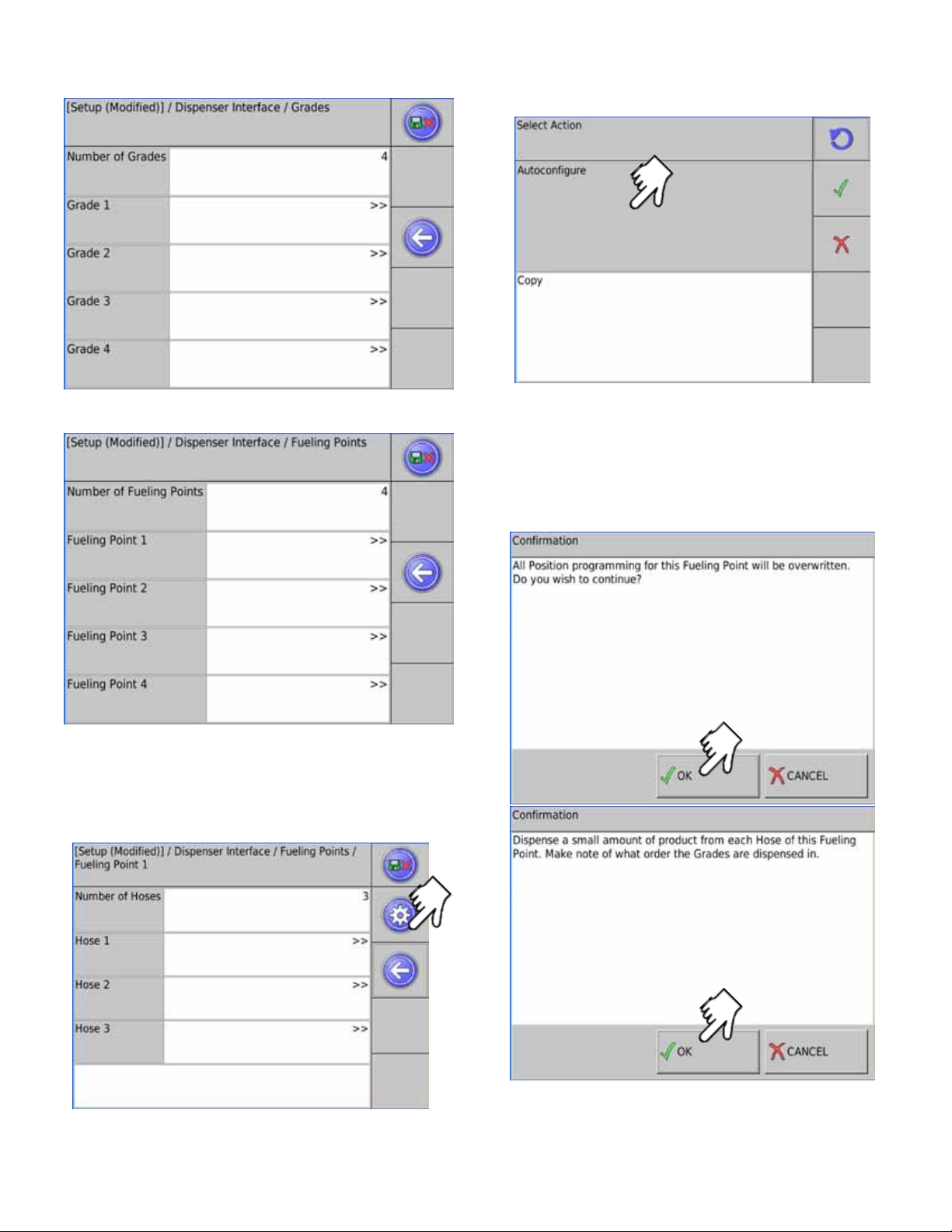
Select each grade and assign a name (i.e. Unleaded
Regular).
This will allow the console to automatically program hose
information (grade association and position) for the Fueling
points based on information received from the D-box.
4. Enter the number of fueling points. In this example
there are 4.
5.
Select Fueling Point 1 and program the number of
hoses. For this example there are 3 available grades
at FP1 and FP2. (number of hoses =3)
and 4 grades available at FP 3 and 4 (number of
hoses = 4). Continue to enter the number of hoses
for each fueling point.
7. Follow the instructions on the screen.
Note: Dispensing small amounts of fuel from each hose
is required before copying the information to other
fueling points that have the same number of hoses.
Run Autocongure before copy.
Conrmation Screens:
10
6. After the number of hoses are programmed, push
the auto-conguration button for fueling point 1.
This will allow the console to verify grade and fueling point
assignments.
Page 11

This action will copy the grade association and position
information to the other Fueling points.
Next Screen
[Setup] / Fuel Management System
Parameter Name Parameter Value Description Value
Ullage Percent (95) Percent of tank level used to calculate space left. 70-100 %
Delivery Delay (15 min) Time after delivery when increase is reported. 1 - 240 min.
Correction
Temperature
High Product Limit Level
Static Tank Testing See Below
Tanks See Below Choose number and types of tanks
Special Tanks See Below Congure non-standard tanks
Manifolds See Below
Products See Below Choose name and type of products
Grades* See Below
Reconciliation* See Below
Autocalibration* See Below
(15.50 °C) Product temperature correction. -15 to 37.78 °C
Choose Volume or Level. This will inuence how
high product alarm is programmed.
Level or volume
* Requires TS-TRAC option
11
Page 12

[Setup] / Fuel Management System / Static Tank Testing
Parameter Name Parameter Value Description Value
Region United States Choose United States, Spain or Other (regulatory) abc#
Monthly Leak Test
Threshold
Yearly Leak Test
Threshold
Sentinel Mode
Threshold
Condence (99%) Leak testing condence. 90, 95, 97.5,
Minimum Leak Test
Time
Maximum Leak Test
Time
Alarm On Precision
Leak Test Failure
[Setup] / Fuel Management System / Tanks
Parameter Name Parameter Value Description Value
Name (Tank 1) Given name of tank. abc#
Type (Special 1) Type of tank. Std./Spcl.
Manifolded (No)
Product # (1) Product # In tank 1-48
Delivery Threshold (757.1 liter) Level increase needed to signal delivery >0.3
Theft Threshold (18.9 liter)
Monthly Compliance Yes
Annual Compliance Yes
Probe
Limits
(0.21) Set static leak tolerance for monthly testing tanks. # cc/sec
(0.11)
(3.15)
(2 hr)
(8 hr)
(No)
Set static leak tolerance for yearly testing tanks.
Set static leak tolerance for Sentinel Mode.
Minimum amount of time used to test.
Maximum amount of time used to test.
Yes will produce an alarm upon leak test failure.
Part of a tank Manifold?
Level decrease needed to signal theft. Note: console
must be in Sentinel Mode
Track this tank under monthly section of compliance
page.
Track this tank under annual section of compliance
page.
(See below)
(See below)
# cc/sec
# cc/sec
99 %
0-8
1-8
Yes/No
Yes / No
>0.3
Yes / No
Yes / No
12
[Setup] / Fuel Management System / Tanks /
Tank 1 / Probe
Parameter
Name
Channel (Probe 1) Channel used for the probe in tank. Probe
Type (Standard 29) Type of probe used in this tank. Std./Spcl.
Ratio (1 to 1 tip to head) Ratio of product level movement in proportion to
Float Type (4 in gas) Type of oat(s) used on probe. 4, 3, or 2 in.
Water Float Yes Indicates if water oat is on probe. Yes / No
Gradient (8.99046 µs/mm) Speed of probe wire. # µs/mm
Product Offset (0.00 mm) Used for compensation of tank tilt. # mm
Water Offset (0.00 mm) Used to compensate for debris on tank bottom. # mm
Parameter Value Description Value
1:1; 7:1; 9:1
the oat
Gas/Diesel,
Stainless,
LPG, Density
Page 13

[Setup] / Fuel Management System / Tanks /
Tank 1 / Limits
Parameter Name
High High Product
(Level) Limit
High Product
(Level) Limit
High Water Level
Limit
Low Product
Volume Limit
Low Low Product
Volume Limit
Parameter
Value
(63.5 liter) (cm)
(58.4 liter) (cm)
(5.1 cm)
(847.9 liter)
(832.8 liter)
Description Value
Product level needed to cause alarm. Units depend on
whether Level or Volume was chosen for high product limit.
Product level needed to produce alarm. Units depend on
whether Level or Volume was chosen for high product limit.
Water level needed to produce alarm.
Product level needed to produce alarm. Units depend on
whether Level or Volume was chosen for low product limit.
Product level needed to produce alarm. Units depend on
whether Level or Volume was chosen for low product limit.
[Setup] / Fuel Management System / Special Tanks
Special #
Parameter Name Parameter Value
Shape
Length (160)
Diameter (28)
End Type (Cylinder)
Correction Table
(Horizontal
Cylinder)
Choose tank shape Horizontal or
Enter Tank Length
Enter Tank Diameter
Describe tank end type Cylinder, one or
Number of points
Description
# liters (cm)
# liters (cm)
# cm
# Liters (cm)
# Liters (cm)
Value
Vertical Cylinder,
Rectangular
0-1200 in.
0-1200 in.
two domed ends
0-100
The Correction Table is used to adjust tank
characteristics by correlating known volume with
a known level. The table is more reliable when
more points are known.
Note: For the following information, Setup / Fuel Management System / Tanks / Manifolded must be set to Yes.
[Setup] / Fuel Management System / Manifolds
Manifold #
Parameter Name Parameter Value
Name (Manifold 1)
Product # (1)
Delivery Threshold (757.1)
Theft Threshold (18.9)
Monthly Compliance Yes
Limits
SCALD
Enter manifold name
Product # In tank
Level increase needed to signal delivery
Level decrease needed to signal theft. Note: console must be in
Sentinel Mode
Track this manifold under monthly section of compliance page
Sets high and low level limits (see table top of page 11)
Enable, Qualify and Diagnostic Modes
Description
Value
abc#
1 - 48
# liters
# liters
Yes / No
Note: SCALD (Statistical Continuous Automatic Leak Detection) tank test runs continuously and requires and detects
quiet times of no dispensing or deliveries.
13
Page 14

[Setup] / Fuel Management System / Products
Product #
Name (Product 1)
Type (Unleaded
Regular)
Enter Product name
Select type of fuel Unleaded Regular, Plus,
[Setup] / Fuel Management System / Grades
Grade #
First Tank (Tank 1)
Second tank (none) Select tank number for second tank
Select tank number for rst tank
[Setup] / Fuel Management System / Reconciliation
abc#
Extra, Super, Diesel,
Kerosene, #2 Fuel Oil,
Ethanol, Special #
(20 Characters maximum)
Tank 1-6
None, Tank 1-6
Parameter Parameter Value
Over Short Limit
Percent
Over Short Limit
Volume
Sales yes
Deliveries Yes
Tank Volume Yes
(1.00)
(130)
Enter short limit percent
Enter short limit volume
Include Sales
Include Deliveries
Include tank volume
Description
Value
0-100
#
Yes / No
Yes / No
Yes / No
[Setup] / Fuel Management System / Autocalibration
Note: Must have Dispenser Interface connected for Autocalibration to work
Parameter Parameter Value
Autostop Volume
Coverage
Autostop Level
Coverage
Autostop Number of
Points Coverage
(100)
(80)
(100)
Enter volume percent at which the Autocalibration
will automatically stop.
Enter level percent at which the Autocalibration
will automatically stop.
Enter number of points required at which the
Autocalibration will automatically stop.
Any of these parameters values can be set separately. If any of the values are met the autocalibration will stop.
• If you want a certain volume coverage, set volume to desired percentage and level and number of points to 100.
• If you want a certain level coverage, set level to desired percentage and set volume and number of points to 100.
If you want so many points in the table, set number of points to desired number and set volume and level coverage to 100.
•
Description
Value
0-100
0-100
0-100
If you have accurate tank dimensions entered, you may not need Autocalibration. Refer to Appendix F for detailed
information on setting up and running Autocalibration.
14
Page 15

E-Mail Setup
[Setup] / E-Mail
Note: This is only needed if you have an Ethernet connection and want the system to send e-mail messages.
Parameter Parameter Value
“From” Address
SMTP Host
SMTP Port 25
Enable Authentication No
Maximum Queue Size 20
Retry Timeout 3600
Watchdog Timeout 30
Enable Debugging No Keeps record of communication attempts Yes / No
your_from@
address.com
Your SMTP host
address
Enter e-mail address of sender (console) abc#
Enter I.P. address of SMTP host
Port address of SMTP
Data authentication (if required)
Maximum size of queue in Megabytes
Time, in seconds, that the console will wait before
attempting to resend the message.
Time, in seconds, that the console self-monitoring
program waits when it expects an error due to
software or power quality problems.
Description
Value
(40 Characters Maximum)
abc#
(40 Characters Maximum)
0-65535
Yes / No
0-200
86400 max
0-300
System Sentinel AnyWare
[Setup] / System Sentinel AnyWare
Note: This section of Set-up is only required if the console is going to transmit data to SSA. It will require the assistance
of the SSA Administrator to set up.
Setup would require:
1. Contact an SSA Administrator.
2. The console must be connected through an Ethernet connection.
3. The SSA Administrator must create a site on SSA.
4. On the SSA Site / Setup page there is an EPS option.
5. Click on EPS.
6. You will be prompted with a note “Program EPS for this site?”
7. Click yes, and the program will automatically enter the values in the table below.
Parameter Parameter Value
IP Address
Port 80
IP address of SSA server abc#
The port that the SSA server uses
Description
Value
(40 Characters Maximum)
#
Path
Priority Highest
Database Connection SSA1
Database User Name SSAADMIN
Database User
Password
Site ID (0) Can leave this at 0. #
/ssa/_data/ssa_
webdata.dll
This is the Web Data URL located on the SSA
server but without the http:// and the domain
name.
Sets communication priority. Leave this at High or
Highest.
Name of Database. For most applications this is
left blank.
Name used to access the database abc#
Password of the user above to access the
database.
(40 Characters Maximum)
Highest, High, Normal, Low
(40 Characters Maximum)
(40 Characters Maximum)
(40 Characters Maximum)
abc#
abc#
abc#
15
Page 16

Rules
Rules associate an event (i.e. alarm, delivery, tank test, etc.) with an action (i.e. activate relay, e-mail, sound, etc.).
[Setup] / Rules
List of Default Rule Entries
These rules can be enabled or modied as needed for local conditions.
Rule - Power On Sound
Rule - Application Event Sound
Rule - New Alarm Sound
Rule - Print Inventory Daily
Rule - Print Tank Test Weekly
Rule - Print SCALD Test Weekly
Rule - Print Regulatory Monthly
Rule - Print on Delivery
Rule - Print on Alarm
Rule - Start Tank Test
Rule - E-mail Alarms
Rule - Set Reconciliation Period
[Setup] / Rules / Rule - Any
Rules
The table below lists parameters for rule making.
Note: The values shown will change depending upon the selection made.
Group Name Parameter Name Parameter Value Description Options
Rules
Rule – New Rule # Name (New Rule #) Given name of rule. abc#
Events
Event
Action
Action Type (e-mail) Action that will occur upon event E-mail, Report, Relay, Tank
Enabled
Type (Alarm Occurred) Event type that triggers action. Alarm Occurred;
Category (Any) System that event occurs in to trigger
Code (Any) Error/Trouble Event Code that
Device (Any) Device that created the alarm
State (Any) State of alarm to trigger action. Various
Address your,email@address.com Where it will send e-mail
Contact Generated What e-mail format is used Generated, Text, HTML, Other
Template Text E-mail Template HTML, Text, short text
(No)
Yes to enable rule.
action.
triggers action.
condition.
Testing, Sentinel mode,
Reconciliation, sound, Notify
SSA, Sample input
Yes/No
Alarm Cleared;
Application Event;
Schedule
Any;
System;
FMS;
(see below)
Various
You can nd samples of creating rules (in English) on the internet. Sign in at http://techlab.franklinfueling.com and locate
FMS/Colibri, or search video libraries
16
Page 17

Operation
Check Inventory
Select the tank.
View or print tank information.
Check Deliveries
Choose the tank or manifold (Tanks shown)
17
Page 18

Alarms
This will bring up a list of current or active alarms. Refer to
Appendix A, Alarm Table.
Print Reports
This shows manifolds. Separate tanks will be listed if tanks
are not connected together with manifolds.
Choose the type of report.
18
Page 19

Web Browser Interface
Connecting to the Console
To use the Web Browser Interface, the console must be connected to a computer. You can connect to the console’s
Ethernet connection using an RJ-45 cable.
Ethernet Connection:
Router or Hub
Use network
cross-over cable
Use network
straight cable
To set up a connection, from the console:
Changing IP settings require administrator sign-on.
The numbers you get may be different than shown. Copy these
numbers for the next step.
Connect the PC to the console with an Ethernet cable.
In M.S. Windows, click on Start:
19
Page 20

Click
Right Click and select Properties
Enter the numbers from the [Home] Conguration IP Address Settings
Page of the console, EXCEPT: Change the IP Address to a different
value (i.e. 192.168.168.167)
Select Properties
Click OK after setting properties
Click OK
Open the computer’s internet browser and put the console’s IP address into the address bar of the browser.
A screen should open similar to that below.
Access Level
Alarm Indicator
The menu selections are the same as shown earlier for the console.
20
Software Version
Page 21

Web Interface Available Pages
The following pages can be viewed in order to see data and perform control functions. Several pages and functions are
controlled by access level. If the Auto Refresh action is listed on the Action Bar of a page, then the data on the page does
not refresh automatically. Click Refresh on your browser to update the page or click on Auto Refresh to have the screen
updated continuously.
Auto refresh
Menu
System
Page Description
Status Displays alarm status for all applications.
Alarms Shows a detailed list of all active Alarms and Warnings.
Reports Make alarm and application event reports.
Conguration Edit the access level passwords and IP information. (Administrator Only)
Registration View the installed options.
Diagnostics Displays SCALD status and Relay status
Tools Allows rebooting system, erase archives or restore factory defaults
About Lists manufacturer contact information
FMS
Page Description
Status Third navigation line appears showing tank inventory information and alarm status.
Alarms Lists all active alarms and the date and time they occurred.
Control Start tank tests, Set Auto-Calibration and calibrate probes.
Compliance Displays compliance information for all tanks.
Reports Make various reports like Inventory, Delivery, Tank Tests and Regulatory.
Setup / Cong
Refer to pages 8-14 for information. This menu and should only be used by a certied technician. See your Franklin
Fueling distributor for assistance.
Preferences
Change the way that data is displayed, change the units of measure and adjust the Auto Refresh rate. There are two
levels of preferences:
Preference Description
Personal These settings are saved and viewed only on your computer.
System Changes the way data is displayed for all Web Browser Interfaces and touch screen users.
Tank Leak Testing Using the Web Browser Interface
Before starting a tank leak test, wait 6 hours after the last delivery and 2 hours after last dispense in order for the tank to
become stable.
There must be no dispense during a tank leak test.
Tank leak tests can take from 2-8 hours to complete. (See Appendix E)
1. Open your web browser and connect to the site.
2. On the Primary Navigation Bar, select FMS.
3. On the Secondary Navigation Bar, select Control.
4. Select Tanks.
Tank Leak Tests
1. Check the box next to the Tank(s) you want to test.
2. From the drop-box, select the type of test (Monthly or Annual) you want to perform for each tank, .
3. Click on Start Leak Tests on the Action Bar.
21
Page 22

Appendix A: List of Alarms
FMS
Tank/Manifold Alarms
Displayed Alarm Description Recommended Actions
Correction Table
Error
Manifold Gross Leak
Detected
Manifold Leak
Detected
Manifold SCALD Leak
Detected
Manifold Theft
Detected
Tank Gross Leak
Detected
Tank Leak Detected The tank listed with the alarm has
Tank SCALD Leak
Detected
Tank Theft Detected Product level in the tank listed with
Correction points for the special tank
listed with the alarm were not entered
or were entered incorrectly.
The manifold listed with the alarm has
failed a Gross Leak Test.
The manifold listed with the alarm has
failed a Monthly Leak Test.
The manifold listed with the alarm has
failed a SCALD Leak Test.
Product level in the manifold listed
with the alarm has dropped below the
programmed Theft Limit.
The manifold listed with the alarm has
failed a Gross Leak Test.
failed a Monthly Leak Test.
The tank listed with the alarm has
failed a SCALD Leak Test.
the alarm has dropped below the
programmed Theft Limit.
Verify that the correction table points for the tank listed with the
alarm are entered sequentially in ‘Special Tanks’ Programming.
Review manifold leak test history and programming. It may be
necessary to manually start a Gross Leak Test to keep the manifold
in compliance.
Review manifold leak test history and programming. It may be
necessary to manually start a Monthly Leak Test to keep the
manifold in compliance.
Review manifold leak test history diagnostic web page and
programming.
Verify that the programmed Theft limit is correct. Verify that the
values of product loss on the console correspond with actual
product loss in the tank.
Review manifold leak test history and programming. It may be
necessary to manually start a Gross Leak Test to keep the tank in
compliance.
Review tank leak test history and programming. It may be
necessary to manually start a Monthly Leak Test to keep the tank in
compliance.
Review tank leak test history and programming. Test to keep the
tank in compliance.
Verify that the programmed Theft Limit is correct. Verify that the
values of product loss on the console correspond with actual
product loss in the tank.
22
Page 23

FMS
Probe Alarms
Displayed Alarm Description Recommended Actions
Float Height
Error
Float Missing A oat on the probe listed with the alarm
High Water
Level
High Product
Level
High High
Product Level
Low Product
Level
Low Low
Product Level
No Probe
Detected
Probe
Synchronization
Error
RTD Table Error The RTD Table programmed for the probe
Temperature
Error
Unstable Probe This alarm indicates inconsistent data from
A oat on the probe listed with the alarm is
being monitored at a varying height outside
of thresholds. Causes can include broken
oat and programming, or mistakenly
associating a gasoline and diesel oat.
has not been detected or the probe was
programmed with the incorrect number of
oats.
The water oat on the Tank/Manifold listed
with the alarm is above the programmed
High Water Level Limit.
The product oat on the Tank/Manifold listed
with the alarm is above the programmed
High Product Level Limit. Tank may be close
to an overfull condition.
The product oat on the Tank/Manifold listed
with the alarm is above the programmed
High High Product Level Limit. Tank may be
near an overfull condition.
The product oat on the Tank/Manifold listed
with the alarm is below the programmed Low
Product Level Limit. Tank may be close to an
empty condition.
The product oat on the Tank/Manifold listed
with the alarm is below the programmed Low
Low Product Level Limit. Tank may be near
an empty condition.
This alarm indicates a communication error
between the console and the probe listed
with the alarm.
This alarm indicates a communication error
between the console and the probe listed
with the alarm.
listed with the alarm is incorrect.
This alarm indicates a temperature sensor
error or failure inside the probe shaft of the
probe listed with the alarm.
the probe listed with the alarm.
Verify Probe programming. Visually inspect that the probe oat type
matches the type of product. Inspect magnet and probe shaft for
cracks or debris and clean if necessary.
Verify the ‘number of oats’ in Probe programming. Number of
oats must match number of oats installed. Float must be lower
than 5" from the bottom of the probe head.
Verify that the programmed limit is correct. Verify that the Water
Level values on the console correspond with the actual water level
in the tank.
Verify that the programmed limit is correct. Verify that the Gross
Product Level values on the console correspond with actual product
level in the tank.
Verify that the programmed limit is correct. Verify that the Gross
Product Level values on the console correspond with actual product
level in the tank.
Verify that the programmed limit is correct. Verify that the Gross
Product Level values on the console correspond with actual product
level in the tank.
Verify that the programmed limit is correct. Verify that the Gross
Product Level values on the console correspond with actual product
level in the tank.
Verify Probe programming. Inspect the probe wiring from the probe
module to the probe.
Verify Probe programming. Inspect the probe wiring from the probe
module to the probe.
Verify the RTD Table programming.
Verify the RTD Table programming. Visually inspect probe shaft for
defects and cracks.
Inspect the probe wiring from the probe module to the probe. Verify
that the product in the tank is both physically and thermally stable.
23
Page 24

FMS
Special Product Alarms
Displayed Alarm Description Recommended Actions
Alpha Volume
Correction Error
API Volume
Correction Error
Level Error The level of the product oat on the probe
Net Error The net volume of the product oat on the
Product Volume
Error
Ullage Error The Ullage level on the tank/manifold listed
Water Volume
Error
If the tank is not listed as a standard tank in Appendix B: Standard Tanks Table, use the tank chart from the manufacturer to create a
custom correction table.
These Alarms refer to temperature correction
coefcients used by the console to calculate
Net Volume. When these values are entered
too high or too low, an alarm condition will
occur.
These Alarms refer to temperature correction
coefcients used by the console to calculate
Net Volume. When these values are entered
too high or too low, an alarm condition will
occur.
listed with the alarm has exceeded a possible
level according to the programming.
probe listed with the alarm has exceeded
a possible volume according to the
programming; related to Volume Correction.
The volume of the product oat on the probe
listed with the alarm has exceeded a possible
volume according to the programming.
with the alarm has exceeded a possible level
according to the programming.
The Water Volume on the tank/manifold listed
with the alarm has exceeded a possible level
according to the programming.
Verify that the Volume in the Correction Type matches the
specications of the product used in ‘Special Products’
Programming. These values should be listed in the product
manufacturer’s Spec Sheets.
Verify that the Volume in the Correction Type matches the
specications of the product used in ‘Special Products’
Programming. These values should be listed in the product
manufacturer’s Spec Sheets.
Verify that the following parameters are programmed correctly
according to site specications: Correction Table, Gradient, Probe
Type, and Product Offset.
Verify that the following parameters are programmed correctly
according to site specications: Correction Table, Gradient, Probe
Type, and Product Offset.
Verify that the following parameters are programmed correctly
according to site specications: Correction Table, Gradient, Probe
Type, and Product Offset.
Verify that the following parameters are programmed correctly
according to site specications: Correction Table, Gradient, Probe
Type, and Product Offset.
Verify that the following parameters are programmed correctly
according to site specications: Correction Table, Gradient, Probe
Type, and Product Offset.
24
Page 25

Appendix B: Standard Tank Table
Legend
O/C = Owens Corning / FC Fluid Containment
D = Diameter (Dia.)
L = Length
S = Single Wall
DW = Double Wall Tank (DWT)
Type #
01 O/C Tanks D5
02 O/C Tanks D-5
03 O/C Tanks D-2B
04 O/C Tanks DWT-2 (6) 2,500 75 x 151 DW
05 O/C Tanks D-6
06 O/C Tanks G-5
07 O/C Tanks G-3 4,000 92 x 165 S
08 O/C Tanks D-6
09 O/C Tanks G-3 6,000 92 x 231 S
10 O/C Tanks DWT-2 (8) 6,000 95 x 237 DW
11 O/C Tanks G-3 8,000 92 x 300 S
12 O/C Tanks G-5
Manufacturer Model Capacity
(Gallons)
550
DWT-4 (4)
DWT-4 (4)
D-6
DWT-2 (6)
G-6
DWT-2 (6)
550
1,000
1,000
2,000
2,000
4,000
4,000
4,000
4,000
6,000
6,000
8,000
Dimensions
D x L (inches)
48 x 78
51 x 83
50 x 132
53 x 138
74 x 133
74 x 133
74 x 236
75 x 239
92 x 167
95 x 167
74 x 354
75 x 357
92 x 299
S / DW
Wall
S
DW
S
DW
S
S
S
DW
S
S
S
DW
S
G-6
DWT-2 (8)
13 O/C Tanks DWT-2 (6) 8,000 75 x 472 DW
14 O/C Tanks G-3 10,000 92 x 362 S
15 O/C Tanks G-5
G-6
16 O/C Tanks D-6 10,000 120 x 245 S
17 O/C Tanks DWT-2(6) 10,000 75 x 570 DW
18 O/C Tanks G-3 12,000 92 x 432 S
19 O/C Tanks G-5
G-6
DWT-2(8)
20 O/C Tanks DWT-2(10) 15,000 124 x 348 DW
21 O/C Tanks DWT-2(10) 20,000 124 x 458 DW
22 O/C Tanks DWT-2(10) 25,000 125 x 554 DW
23 Xerxes DWT-2(10) 30,000 124 x 656 DW
24 Xerxes — 2,000 96 x 108 S
8,000
8,000
10,000
10,000
12,000
12,000
12,000
95 x 299
95 x 303
92 x 365
95 x 365
92 x 431
95 x 431
95 x 435
S
DW
S
S
S
S
DW
25
Page 26

Type #
25 Xerxes — 2,000 76 x 166 DW
26 Xerxes — 2,000 75 x 144 S
27 Xerxes — 3,000 96 x 147 S
28 Xerxes — 4,000 75 x 263 S
29 Xerxes — 4,000 96 x 180 S
30 Xerxes — 4,000 76 x 252 DW
31 Xerxes — 6,000 75 x 353 S
32 Xerxes — 6,000
33 Xerxes —
Manufacturer Model Capacity
(Gallons)
6,000
8,000
Dimensions
D x L (inches)
96 x 246
97 x 251
96 x 312
S / DW
Wall
S
DW
S
—
34 Xerxes —
—
35 Xerxes —
—
36 Xerxes —
—
37 Xerxes —
—
38 Xerxes —
—
39 Xerxes —
—
40 Corespan — 4,000 99 x 162 DW
41 Corespan — 5,000 99 x 192 DW
42 Corespan — 6,000 99 x 216 DW
43 Corespan — 8,000 99 x 282 DW
44 Corespan — 10,000 99 x 342 DW
45 Corespan — 12,000 99 x 402 DW
46 Corespan — 15,000 99 x 576 DW
47 — — 275 44 Vertical S
48 — — 550 44 Vertical (Dual
49 — — 275 44 Horizontal S
8,000
10,000
10,000
10,000
10,000
12,000
12,000
12,000
12,000
15,000
15,000
20,000
20,000
97 x 317
96 x 378
97 x 383
124 x 257
125 x 262
96 x 444
97 x 449
124 x 288
125 x 293
124 x 353
125 x 359
124 x 452
125 x 458
275 gal.)
DW
S
DW
S
DW
S
DW
S
DW
S
DW
S
DW
S
26
Page 27

Appendix C: Compatible Printers
Hewlett Packard Compatible Printers
Colibri consoles have a standard Type-A USB socket on the bottom of the console. The console uses Printer Control
Language (PCL) version 3 or higher protocol developed by Hewlett Packard (HP) to print to external printers.
Colibri consoles have two standard Type-A USB sockets on the bottom of the console. The console uses Printer Control
Language (PCL) versions 3 through 5 protocols developed by Hewlett Packard (HP) to print to external printers.
PCL 6 is not compatible with the Colibri consoles. However, many printers with PCL 6 can also support PLC 5. It is also
important to note that PCL 3 GUI is a subset of PCL 3 and is not compatible with the Colibri consoles.
Franklin Fueling Systems recommends the following HP printers:
• HP Deskjet 6940
• HP LaserJet P1505n.
Important Note
• Do not use printers with a power save feature
• Start the printer before starting the console
Appendix D - Standard Products Table
Product Name API Gravity (6B Compensation)
Leaded Regular 63.5
Unleaded Regular 63.5
Unleaded Plus 62.8
Unleaded Extra 62.8
Unleaded Super 51.3
Diesel 32.8
Kerosene 41.8
#2 Fuel Oil 32.8
Appendix E - Typical Tank Leak Test Times
For 7 Tank Sizes at Half Capacity ( Worst Case is 50% Full )
Tank Size in Gallons Typical - Tank Leak Test Times (to Finish)
4,000 2.0 hours
6,000 3.0 hours
8,000 4.0 hours
10,000 5.0 hours
12,000 6.0 hours
15,000 7.5 hours
20,000 8.0 hours
Note: The Leak Threshold value is one half of the Leak Test value.
27
Page 28

Appendix F - Using the Console’s Autocalibration Feature
Using the Autocalibration Feature on an FFS
Tank Gauge
Introduction
Autocal is a feature of the Colibri Tank Monitoring Systems
which generates a tank strapping chart in order to
accurately calibrate and reconcile your fuel management
system automatically. Autocal compares sale of product
from dispensers with changes in tank volume.
Autocal corrects discrepancies in delivery reporting and
daily reconciliations that are caused by inaccurate tank
information programmed into the ATG. Incorrect tank
information can come from:
• Lack of a tank chart
• Wrong tank chart
• Tank that deforms over time and no longer represents
its tank chart
Autocal Requirements
A high variance on a tank’s Daily Reconciliation Reports,
means that the amount of product owing through the
dispensers appears to be different from the amount leaving
the tank. This could mean that the manufacturer’s tank
chart programmed into the ATG is not accurate, but it can
also be caused by several other things. The following
items should always be checked by a certied service
professional before starting Autocal:
• Autocal cannot be performed on manifolded tanks
• Probes must be properly installed
• Tank tilt calculations must be correct (or 0 if the probe is
at tank center)
• The tank charts provided must be correct
• The tank must be programmed correctly (length,
diameter, correction points)
• Make sure that probe alarms or TS-DIM (Dispenser
Interface Module) problems are not the reason for the
Over / Short status
• Recently passed tank tests and line tests are on le
• The dispenser meters are calibrated
• Your FFS ATG has the Reconciliation option and is
interfaced with a POS / dispenser
• Your FFS ATG has the correct Reconciliation
programming
Note: Calibrating a tank with Autocal that does not meet
the above criteria could potentially cover up a
problem or leak.
Hardware and Software Requirements
An Colibri gauge must have the TS-TRAC internal
software option to perform the Autocal feature. The Colibri
Tank Monitoring System must be doing accurate dispenser
reconciliation.
Autocal Preparation
Determining Sites That May Require Autocal. The following
steps will help determine if an Autocalibration may be
necessary
1. Generate a DIM Reconciliation Report for the last
30 days. Look for tanks that have Over or Short
status on the report.
2. Take note if any days show missing sales or sales
numbers that are unrealistic. These days may
be the reason that the status may show OVER
or SHORT, but they are not reasons for using
Autocal. It is possible that the tank still needs to
be calibrated even if it has some missing days
or data. The “good” days need to be examined
to see if the Daily Variance is usually high. If the
Daily Variance is greater than 10% of the sales
on “good” days, then there is another problem in
the system that needs to be xed prior to starting
Autocal.
28
Page 29

To See If a Tank Is Autocal Ready
• Use the previous month’s DIM Reconciliation Report to
look for explanations for the Over / Short status. A typical
tank that needs calibration will show a consistently
high variance, but not very high. If the Daily Variance
is higher than 10% of the sales for that day, then the
problem is probably being caused by something that will
not be resolved by using Autocal.
• Check the Active Alarms and Alarm History for probe
problems on the tank to be calibrated.
• Check the tank setup. Each tank must have its own
Special Tank, and each tank type must be the Special
Tank of the same number (e.g. Tank 1 type = Special 1,
Tank 2 type = Special 2).
• Make sure that the Tank Length (or estimated Length
for berglass) is programmed correctly. If it is not, there
may be a false delivery recorded at the time between
the old tank chart being cleared and the rst point being
put in. To see how to adjust the length of your tank
correctly, refer to the following section called Adjusting
Length rst.
• Are there any known problems at the site in the past that
might effect variance?
• Record the daily usage from the ATG in order to
estimate how long Autocal will take to complete.
• If Autocal has been attempted before, make sure that it
was stopped and that the original tank information was
programmed back in prior to starting Autocal again.
If the above bulleted points have all been addressed, then
you are ready to start Autocal.
Calibration Procedure
FFS recommends that calibration be started with the
tank lled to more than 90% of its total volume, and that
the tank be then allowed to drain down to at least 10% of
its total volume. When the Autocal program senses 80%
volume coverage, it will end automatically, but it can also
be stopped manually at any time.
As long as the coverage is around 70%, it should be
sufcient. The key is that the new tank chart covers the
level range that the tank stays in during normal operation.
Delivery during Calibration
If a delivery occurs during the Autocal process that raises
the fuel level to a point above the calibration starting point,
Autocal will STOP.
Adjusting Length First
If the Tank Length (or estimated Length for berglass) isn’t
programmed correctly, then there may be a false delivery
recorded at the time between the old tank chart being
cleared and the rst point being entered in. Make sure that
your Tank Length is programmed correctly, and refer to the
appropriate section below based on your tank type.
Flat Ends (Steel)
If the ends of the tank are at so that the tank is a true
cylinder, then the ATG should only need to know the
length and diameter and should not need to be calibrated.
Adjusting the Length may correct the problem.
If the Daily Variance is always negative or always positive,
then it is likely that the Length is wrong. Check the delivery
accuracy, and it will likely show an error also, though
probably in the opposite direction of the variance.
If the Daily Variance is consistently NEGATIVE (with
positive deliveries), then the tank is TOO BIG and the
Length should be shortened and vice versa. Adjust the
Length of the tank. As a rule of thumb, calculate the
average variance for the past ve days. Figure out what
percentage of the total tank volume this average variance
is equal to, and modify the length of the tank by the same
percentage. Monitor the Daily Variance of the modied
tank for several days to see what the effect has been.
Dome Ends (Fiberglass)
If the tank is berglass with domed ends, then there is no
set Length. An approximate Length should be calculated
based on the Diameter and Volume capacity of the tank by
using this formula: Length = 231 (4V/πD2) (for metric units
replace 231 with 10,000,000). Enter the Correction Points
from the manufacturer’s tank chart at least every 5 inches
(12.7 cm) - the more points entered the better.
Length and Volume Unknown
If the Length and Volume of the tank are unknown and you
don’t have a tank chart, then the default reference volume
will not be accurate enough. Follow these steps to obtain,
and enter, an accurate reference volume in the tank:
1. Enter an approximate length.
2. Drain the tank completely dry (the product drop in
the next step will be off by whatever amount is not
removed).
3. Drop an accurately measured amount of fuel into
the tank — the more measured fuel added, the
better.
4. Adjust the Length until the ATG reads about the
same amount as was dropped.
5. Enter the amount dropped as the reference
volume when prompted during the Autocal start.
29
Page 30

Starting Autocal
When Autocal starts, it will need a reference volume as
the starting point for the calibration. The default reference
volume will be what the tank gauge is reading at the
time that Autocal is started. This reading needs to be as
accurate as possible and not higher than the initial
volume read by the ATG, in order to produce a quality
chart. The Diameter, Length, and Correction Points are
what contribute to the default volume’s accuracy. The
diameter of the tank should be listed on the tank chart, but,
if it’s not, then it can be easily measured.
To begin the Autocal process;
1. Select a tank from the Inventory Summary Screen.
2. After selecting the tank, press the (MENU) key in
the upper right hand corner.
3. Next, select Control/Tanks/Autocalibration.
4. Select the tank and this message should
appear “Are you sure you want to perform the
autocalibration on this tank?” Select OK.
30
Page 31

5. The following message will be displayed “Do
you want to enter a reference volume for the
autocalibration?”
6. Select OK and enter a reference volume to start.
The reference volume needs to be slightly less
than the current volume.
After the reference volume is entered, the tank should
have an ACTIVE indication in the (FMS) / Autocalibration
(Tank) screen.
Reasons Why Autocal Would Stop
• Power failure
• Setup entered
• Probe failure
• TS-DIM failure
• Delivery in Tank under Autocal.
Autocal Completion
1. The Autocalibration procedure will stop when the
Percent Coverage is reached.
2. Monitor the Daily Reconciliation and Delivery
Reports for a few weeks to ensure that they are
within tolerance.
Note:
If Autocal stops collecting points for any reason, stop
it, reprogram the original tank chart, and start over.
31
Page 32

©2009 FFS 000-2155 RevA
 Loading...