

Page 1

Colibri
Automatic Tank Gauge
CL6 Series
Installation Guide
Franklin Fueling Systems • 3760 Marsh Rd. • Madison, WI 53718 USA
Tel: +1 608 838 8786 • 800 225 9787 • Fax: +1 608 838 6433 • www.franklinfueling.com
Page 2

Notice
FFS reserves the right to change this document and specications at any time without notice. FFS makes no expressed
or implied warranty with regard to the contents of this manual. FFS assumes no liability for errors or omissions, or for any
damages, direct or consequential, that may result from the use of this document or the equipment that it describes.
Trademarks
FFS®, Colibri®, TS-5 Series®, System Sentinel®, SCALD®, Brite®, BriteBox®, BriteBus®, and BriteSensors® are registered
trademarks of Intelligent Controls. All brand and product names are trademarks or registered trademarks of their
respective companies.
Inspection of Materials
Visually inspect all components for defects or damage prior to installation. If any defect or damage is found, do not use the
product and contact FFS for further assistance.
Return Shipping Charges
FFS will not accept shipments of returned products without a Return Material Authorization (RMA) number. RMAs are
obtained by contacting FFS’s Technical Service Division — NO RMAs will be given without the unit’s serial number(s).
Returned material remains the property of the buyer until replaced or repaired.
Under Warranty
FFS will pay all freight and insurance charges for all “Under-Warranty” RMAs.
Non-Warranty
It is the buyer’s responsibility to prepay all freight and insurance charges for “Non-Warranty” RMAs.
Refer to the Warranty document FFS-0079.
Contacting Franklin Fueling Systems (FFS)
Please feel free to contact us by mail at:
Franklin Fueling Systems
3760 Marsh Rd.
Madison, WI 53718 USA
Or contact us by phone, fax or e-mail:
Tel: 1 608 838 8786 E-mail: sales@franklinfueling.com
Fax: 1 608 838 6433 techserve@franklinfueling.com
Tel: US & Canada 1 800 225 9787
Tel: México 001 800 738 7610
Tel: Europa +49 6571 105 380
Tel: Asia +86 21 6236 8900
Please visit our web site at www.franklinfueling.com
Copyright ©2009 by Franklin Fueling Systems (FFS). No part of this publication may be reproduced in any form without the prior written consent of FFS.
ii
All rights reserved.
Page 3

Contents
Important Safety Messages ....................................................................................................... 1
Introduction ...................................................................................................................................2
Product Description .....................................................................................................................2
Console Installation ..................................................................................................................... 2
Console Location ......................................................................................................................2
Console Dimensions ...................................................................................................................3
Standard Installation Materials .................................................................................................4
Wiring the Console .....................................................................................................................5
Attach the probe wiring in order as shown on the label below.. ...................................................... 5
Non-Intrinsically Safe Wiring. .......................................................................................................... 6
Check Electrical Resistance to Earth Ground ................................................................................. 6
Control Drawing ............................................................................................................................ 8
iii
Page 4
Important Safety Messages
FFS equipment is designed to be installed in association with volatile hydrocarbon liquids such as gasoline and diesel
fuel. Installing or working on this equipment means working in an environment in which these highly ammable liquids
may be present. Working in such a hazardous environment presents a risk of severe injury or death if these instructions
and standard industry practices are not followed. Read and follow all instructions thoroughly before installing or working
on this, or any other related, equipment.
As you read this guide, please be aware of the following symbols and their meanings:
Warning
Caution
Danger
Warning
Warning
Warning
This symbol identies a warning. A warning sign will appear in the text of this document when a potentially
hazardous situation may arise if the instructions that follow are not adhered to closely. A potentially hazardous
situation may involve the possibility of severe bodily harm or even death.
This is a caution symbol. A caution sign will appear in the text of this document when a potentially hazardous
environmental situation may arise if the instructions that follow are not adhered to closely. A potentially
hazardous environmental situation may involve the leakage of fuel from equipment that could severely harm
the environment.
This symbol identies an electrical danger. An electrical danger sign will appear in the text of this document
when a potentially hazardous situation involving large amounts of electricity may arise if the instructions that
follow are not adhered to closely. A potentially hazardous situation may involve the possibility of electrocution,
severe bodily harm, or even death.
Follow all applicable codes governing the installation and servicing of this product and the
entire system. Always lock out and tag electrical circuit breakers while installing or servicing
this equipment and any related equipment. A potentially lethal electrical shock hazard and the
possibility of an explosion or re from a spark can result if the electrical circuit breakers are
accidentally turned on during installation or servicing.
Follow all federal, state and local laws governing the installation of this product and its associated
systems. When no other regulations apply, follow NFPA codes 30, 30A and 70 from the National Fire
Protection Association. Failure to follow these codes could result in severe injury, death, serious
property damage and/or environmental contamination.
When the Colibri system is used to monitor tanks containing gasoline or other ammable
substances, you may create an explosion hazard if you do not follow the requirements in this
manual carefully.
Warning
1
All wiring must enter the console’s enclosure through the designated knockouts. An explosion
hazard may result if other openings are used. All wiring from probes to the console must be run in
conduit separate from all other wiring. Failure to do so will create an explosion hazard.
Page 5
Introduction
This manual contains installation and site preparation
instructions for FFS’s Colibri console. Safety issues,
troubleshooting information, warranty, service, and return
policies, as dened in this manual, must be followed.
Please read this entire manual carefully. Failure to
follow the instructions in this manual may result in faulty
operation, equipment damage, injury or death.
Console Installation
Console Location
Install the console indoors in an area classied as nonhazardous. Locate the console where personnel can
easily make use of it; mount it at eye level for operator
convenience. Mount the console level on a vertical surface
between 2 feet (0.6 m) and 6 feet (1.9 m) high using the
appropriate fasteners.
Installer
This equipment should only be serviced by an FFScertied technician.
Product Description
The Colibri is a complete, automatic, continuous
monitoring system that performs a variety of functions.
• Performs inventory monitoring
• Generates reports automatically in response to
preset / programmed conditions and alarms
• Provides audio-visual annunciation when an alarm or
warning condition exists
• Is able to print reports on an external USB printer.
• Remotely accessible via Ethernet or RS-232 to any web
browser.
• Leak detection and density monitoring
• Tank reconciliation and Autocalibration
Console Specications
Line Voltage:
Frequency & Power: 50/60 Hz, 150 W maximum
Storage Temp.: -20° to 60° C (-4° to 140° F)
Operating Temp.: 0° to 40° C (32° to 104° F)
Operating Humidity: 0 to 95%, non-condensing
Cleaning: Cloth or sponge slightly dampened in
Splash Resistance: Not to be exposed to direct spray, splash
Location: Indoors in an ofce or in a non-
Relay Rating 10A @ 240V~
110-240 V
mild detergent
or drips
hazardous pollution degree 2
environment per IEC60664
~, 1.0 A
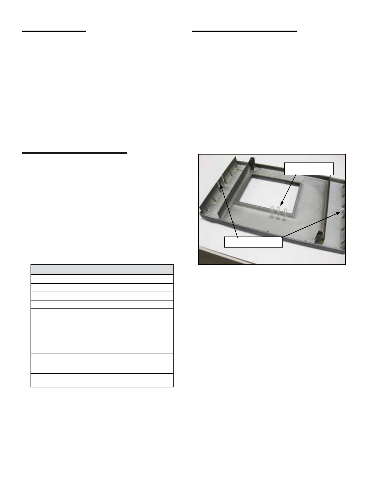
Mounting the Console
Removing the cover
The cover must be removed by lifting with two hands.
Press in on the cover release tabs on both ends to release
the cover and lift it straight away from the unit (Figure 1).
When reinstalling the cover put it on straight so the LED
light pipes are not damaged.
LED Light Pipes
Cover Release Tabs
Figure 1: Inside Cover
The Colibri console must be mounted in a location
where explosive or ammable vapors are not
present, otherwise an explosion hazard will be
created which can result in severe injury, death,
serious property damage and/or environmental
contamination.
Leave a minimum of two inches (5.1 cm) of space
around the console open to allow for ventilation,
communication port connections, conduit and
wiring.
Two mounting screw holes are located on the inside of the
console. Use fasteners that have sufcient load carrying
capacity and which are appropriate for wall construction.
Make sure that there is enough room around the console
for conduit coming into the unit, communication port
connections, probe wiring, and console access.
2
Page 6

Console Dimensions
(235 mm)
9.25"
1.00"
(25.4 mm)
2X
0.21"
(5.33 mm)
Ground stud
See note 2.2
Intrinsically
safe wiring
compartment
Power / relay
Compartment
Probe Interface
Connections
7.27"
(185 mm)
Non-Intrinsically Safe Conduit Entries
11.92"
(303 mm)
Alarm Led
Warning Led
Power Led
Communication Ports
Intrinsically Safe Conduit Entries
Figure 2: Console Dimensions
LCD Display
(Optional)
Cover Release Tab
Both Ends
2.24"
(57 mm)
3
Page 7

Standard Installation Materials
Circuit Breaker
20 Amp — providing power only for the console
Weatherproof Junction Boxes
Minimum 16 cubic inch (406.4 cubic mm) weatherproof
junction box, cover, and cover gasket for the manholes of
liquid level probes. Also use ½ inch (16 mm) bushings for
probe compression ttings.
Use a weatherproof metal pull box for combining several
circuits that will run into the console through one or more
conduits.
Use a separate weatherproof metal pull box to combine
intrinsically safe (IS) liquid level probe wiring. Do not run
other non-intrinsically safe wiring within the IS pull box.
Run ½ inch (16 mm) IS probe conduit from the manholes
to the IS pull box, and then run one or two ½ inch (16 mm)
conduits to the console’s IS conduit knockouts.
Conduit
Rigid metal conduit (RMC) - male NPT threaded: use
½ (16 mm) for IS probe wiring to the console (from the
manholes, use ½ inch conduit), and use ½ inch (16 mm)
for non-intrinsically safe accessories and power wiring.
Use conduit hardware that is appropriate for the installation
and meets local, state and federal requirements.
Splice Connector Kits Must Be Used —
Warranty Requirement
Use the FFS-approved, moisture-resistant, no-strip splice
connectors for liquid level probes. You may order the
TSP-KW30, which contains 30 of the FFS-approved,
moisture-resistant connectors.
Using moisture resistant splice connectors will:
• Reduce / eliminate corrosion of the wire connections from
repeated exposure to water condensation, which causes
eventual signal loss and system failure.
• Reduce or eliminate equipment damage from water
ooding around the connectors, which causes shortcircuit damage.
Thread Sealant (UL Classied)
Use a non-hardening, “stay-soft,” Teon thread sealant,
or equivalent, to seal and waterproof all tank riser pipe
threads. In addition, the thread sealant (or “pipe dope”
as it is commonly known) should also be chemically
non-reactive to the product in the tank(s). Apply thread
sealant to seal / waterproof all outdoor electrical conduit
tting threads including the hole plugs at the weatherproof
junction boxes.
Riser Pipes
ANSI Schedule 40 (or chemically non-reactive) 2" or 4"
(50.8 or 101.6 mm) (8 NPT) riser pipes for liquid level
probes.
Probe Installation Kit(s)
The appropriate FFS 2” or 4” probe installation kit must
be used when installing TSP-LL2 (not -I) leak detection
probes and / or Density Measurement oat kits.
Probe Install Kits:
Part # Description
TSP-K2A For 2" riser pipes, NPT
TSP-K2B For 2" riser pipes with BSP threads
TSP-K4A For 4" riser pipes, NPT
TSP-K4S 316 stainless steel for 4" riser pipes, NPT
TSP-K4B For 4" riser pipes with BSP threads
Probe Floats
• Floats for 4 inch (101.6 mm) riser pipes, order: TSPIGF4 for gasoline applications or TSP-IDF4 for diesel
and fuel oil
Floats for 3 inch (76.2 mm) riser pipes, order: TSP-IGF3
•
for gasoline applications or TSP-IDF3 for diesel and fuel oil
• Floats for 2 inch (50.8 mm) riser pipes, order: TSP-IGF2
for gasoline, TSP-IDF2 for diesel and fuel oils, or
TSP-SSP stainless steel oat for chemical products
• Density oats for 4 inch (101.6mm) riser pipes, order:
TSP-IGF4D for gasoline applications and TSP-IDF4D
for diesel and fuel oil.
Manufacturer’s Tank Chart for Each Tank
The manufacturer’s Tank Chart and other documentation
will be used for installation and programming, and possibly
for future reference. Keep this information — do not
discard it.
44
Page 8

Wiring the Console
Intrinsically Safe Wiring
Non-intrinsically safe wiring cannot be run in the
same conduit as intrinsically safe wiring.
Probe Wiring
The probe wiring is intrinsically safe and kept separate
from all other wiring. Conduit must only enter the console
enclosure through the designated knockouts. Installation
may require the conduit to enter on top or bottom. Do not
loose the conduit plugs and make sure any openings are
covered by the plugs.
Probe Terminals
Figure 3: Probe Wiring
Attach the probe wiring in order as shown on the label
below.
Probe Input Specications
Number of Channels: 6
Safety Rating: Class I, Division 1, Group D, [Ex ia] IIA
Entity Parameters
Uo = 28.35 V
Io = 157.5 mA
Co = 1.04 uF
Lo = 1.4 mH
Po = 1.1 W
Terms dened
Term Denition
Uo Maximum Output Voltage
Io Maximum Output Current
Po Maximum Output Power
Co Maximum External Capacitance
Lo Maximum External Inductance
Cables Required for Liquid Level Probes
Use cables and wires compliant with national and local
codes to insure reliable communication between the
console and probes. To ensure reliable communication
between a console and probes, FFS recommends using
the types of cable shown below up to a recommended
length of:
All cable to be shielded twisted pair, 22AWG or greater
and oil / water resistant.
Distance
feet (m)
Capacitance
(pF)
per foot
500 (152) <100 <0.2
1000 (305) <60 <0.2
1500 (457) <20 <0.3 89182*
Inductance
(µH)
per foot
Belden Cable
87760
87761*
88760
8760
8770
Note: An asterisk (*) indicates cables that may be ordered
from FFS.
5
Page 9
Line Power Wiring
Non-Intrinsically Safe Wiring
Always lock out and tag electrical
Warning
Power to the console must be 110 to 240 V~, 50 / 60 Hz.
At the electrical power panel, use a 20 amp circuit breaker
used only to supply power to the Colibri console.
Note: Do not connect other equipment to this circuit.
circuit breakers while installing or
servicing this equipment and any
related equipment. A potentially
lethal electrical shock hazard and
the possibility of an explosion or re
from a spark can result if the electrical
circuit breakers are accidentally turned
on during installation or servicing.
110/240 VAC Line Power Wire Connection List
Electrical
Panel
20 Amp Circuit
Breaker
Neutral 1 White Wire, 14 AWG (1.6
Ground Bus 1 Green wire, 14 AWG (1.6
Ground Bus 1 Green wire, 12 AWG (2.1
No. Conductors, Color
(Gauge)
1 Black wire, 14 AWG (1.6
mm) min.
mm) min.
mm) min.
mm) min.
Circuit
110/240 VAC
Power
Neutral
Ground
Safety
Ground
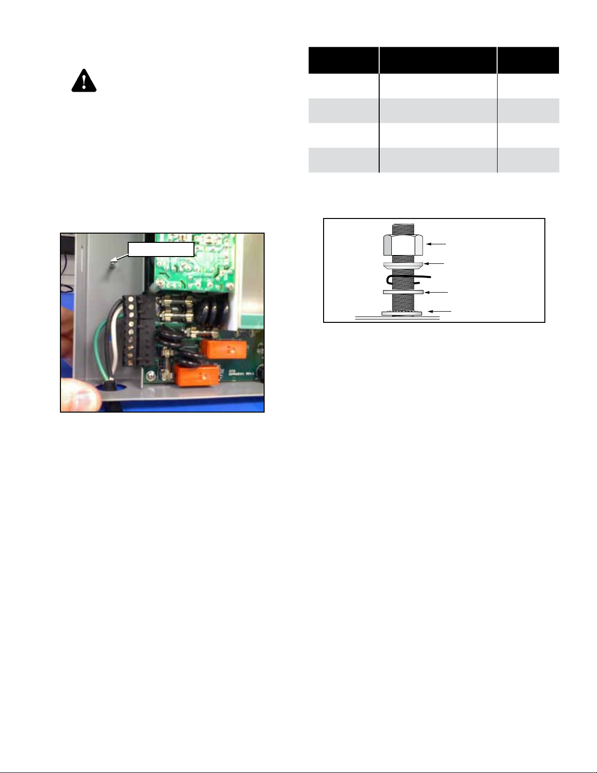
Console Ground Connection
Attach the ground wire to the grounding stud in the
console.
Ground Stud
Figure 4: Power Wiring Connection
The ground bus in the electrical panel must be
connected to an earth ground as required by the
National Electrical Code (or Canadian Electrical Code)
when applicable. If the ground bus is not properly
connected to an earth ground or if the IS safety ground
is not properly connected at the console, a dangerous
condition will be created which could result in an
explosion.
Enclosure
Figure 5: Ground Stud Connection
Nut
Cup Washer
Earth Ground Conductor
Flat Washer
Lock Washer
Check Electrical Resistance to Earth Ground
After wiring the IS safety grounds, check the resistance
between the IS safety ground terminals at the console and
the earth ground – this resistance must be less than 1 ohm.
6
Page 10

Communication Ports
The Colibri console has several communication ports
that can be used to communicate with devices. The
communication ports can be used to connect the console to
a Local Area Network, Point of Sale device, external printer
or modem.
Figure 6: Communication Ports
Port Connector Type Devices
RS-232
Comm 1
Ethernet RJ-45
USB (2) Type A
DB9 Male
* The USB ash drive can be used to collect data or
load upgraded les
Modem, P.O.S. or
local PC
Local network or
computer
External printer,
modem or USB
ash drive*
USB Modem Requirements
In order for the console operating system to communicate
with a USB modem, the modem must be CDC-ACM
compliant.
Printer Requirements
The printer has to have a USB interface and support
Hewlett-Packard Printer Command Language level 3 (PCL
3) or higher. The printer should not have a power save
feature and should be started before starting the console.
Relay Wiring
1
2
4
3
5
6
RS-232 Communication Connectors
One connector for RS-232 interface is provided on the
bottom of the console The pin designations for the RS-232
connectors are as follows:
Console RS-232 Comm Port 1
DB9 Connector, Male, DTE
Pin No. Function Input/Output
1 DCD
2 RD
3 TD
4 DTE
5 Signal GND
7 RTS
8 CTS
I ←
I ←
O
O
O
I
→
→
→
←
Figure 7: Relay Wiring Connection
Relay Terminal Description
1. Normally Closed
1
2. Common
3. Normally Open
4. Common
2
5. Normally Closed
6. Normally Open
Note: Pay close attention to the relay connections. The
position of the Normally Closed and Common
terminals are swapped.
7
Page 11

Control Drawing
Page 12

©2009 FFS 000-2153 Rev. B
 Loading...