

Franke FTU 3807- P XS 70 H User Manual
IT
GB
FR
DE
TR
PL
CZ
Istruzioni per l’uso e l’installazione
Cappa
Instructions for use and installation
Cooker Hood
Mode d’emploi et installation
Hotte de Cuisine
Bedienungsanleitung und Installation
Dunstabzugshaube
Kullanım ve montaj talimatları
Davlumbaz
Instrukcja obsługi i instalacji
Okap kuchenny
Uživatelská Pøíruèka
Odsavač par
FTU 3807-P WXS 70H
FTU 3807-P WXS 90H

INDICE
CONSIGLI E SUGGERIMENTI.............................................................................................................................................. 4
CARATTERISTICHE.............................................................................................................................................................. 7
INSTALLAZIONE ................................................................................................................................................................... 9
USO...................................................................................................................................................................................... 14
MANUTENZIONE ................................................................................................................................................................ 15
IT
INDEX
RECOMMENDATIONS AND SUGGESTIONS ................................................................................................................... 17
CHARACTERISTICS ........................................................................................................................................................... 20
INSTALLATION.................................................................................................................................................................... 22
USE ...................................................................................................................................................................................... 27
MAINTENANCE................................................................................................................................................................... 28
EN
SOMMAIRE
CONSEILS ET SUGGESTIONS.......................................................................................................................................... 30
CARACTERISTIQUES......................................................................................................................................................... 33
INSTALLATION.................................................................................................................................................................... 35
UTILISATION .......................................................................................................................................................................40
ENTRETIEN......................................................................................................................................................................... 41
FR
INHALTSVERZEICHNIS
EMPFEHLUNGEN UND HINWEISE ................................................................................................................................... 43
CHARAKTERISTIKEN......................................................................................................................................................... 46
MONTAGE ...........................................................................................................................................................................48
BEDIENUNG........................................................................................................................................................................ 53
WARTUNG........................................................................................................................................................................... 54
DE
IÇERIKLER
TAVSIYELER VE ÖNERILER.............................................................................................................................................. 56
ÖZELLIKLER........................................................................................................................................................................ 59
MONTAJ............................................................................................................................................................................... 61
KULLANIM ........................................................................................................................................................................... 66
BAKIM .................................................................................................................................................................................. 67
TR
SPIS TREŚCI
UWAGI I SUGESTIE............................................................................................................................................................ 69
WŁAŚCIWOŚCI TECHNICZNE........................................................................................................................................... 72
INSTALACJA........................................................................................................................................................................ 74
UŻYTKOWANIE................................................................................................................................................................... 79
KONSERWACJA ................................................................................................................................................................. 80
PL
2
2

OBSAH
RADY A DOPORUČENÍ ...................................................................................................................................................... 82
HLAVNÍ PARAMETRY......................................................................................................................................................... 85
INSTALACE ......................................................................................................................................................................... 87
POUŽITÍ ............................................................................................................................................................................... 92
ÚDRŽBA............................................................................................................................................................................... 93
CZ
3
3
CONSIGLI E SUGGERIMENTI
Le Istruzioni per l’uso si riferiscono ai diversi modelli di questo
apparecchio. Pertanto, si potrebbero trovare descrizioni di singole
caratteristiche che non appartengono al proprio apparecchio specifico.
INSTALLAZIONE
• Il fabbricante non potrà ritenersi responsabile per eventuali danni risultanti
da un’installazione o utilizzazione impropria.
• La distanza minima di sicurezza tra il piano cottura
e la cappa aspirante è di 650 mm (alcuni modelli
possono essere installati a un’altezza inferiore;
vedere il paragrafo relativo alle dimensioni di lavoro
e all'installazione).
• Controllare che la tensione di rete corrisponda a
quella indicata sulla targa dati applicata all’interno
della cappa.
• Per gli apparecchi di Classe I, controllare che la rete di alimentazione
domestica disponga di un adeguato collegamento a massa.
Collegare l'aspiratore al condotto dei fumi mediante un tubo con diametro
minimo di 120 mm. Il percorso dei fumi deve essere il più corto possibile.
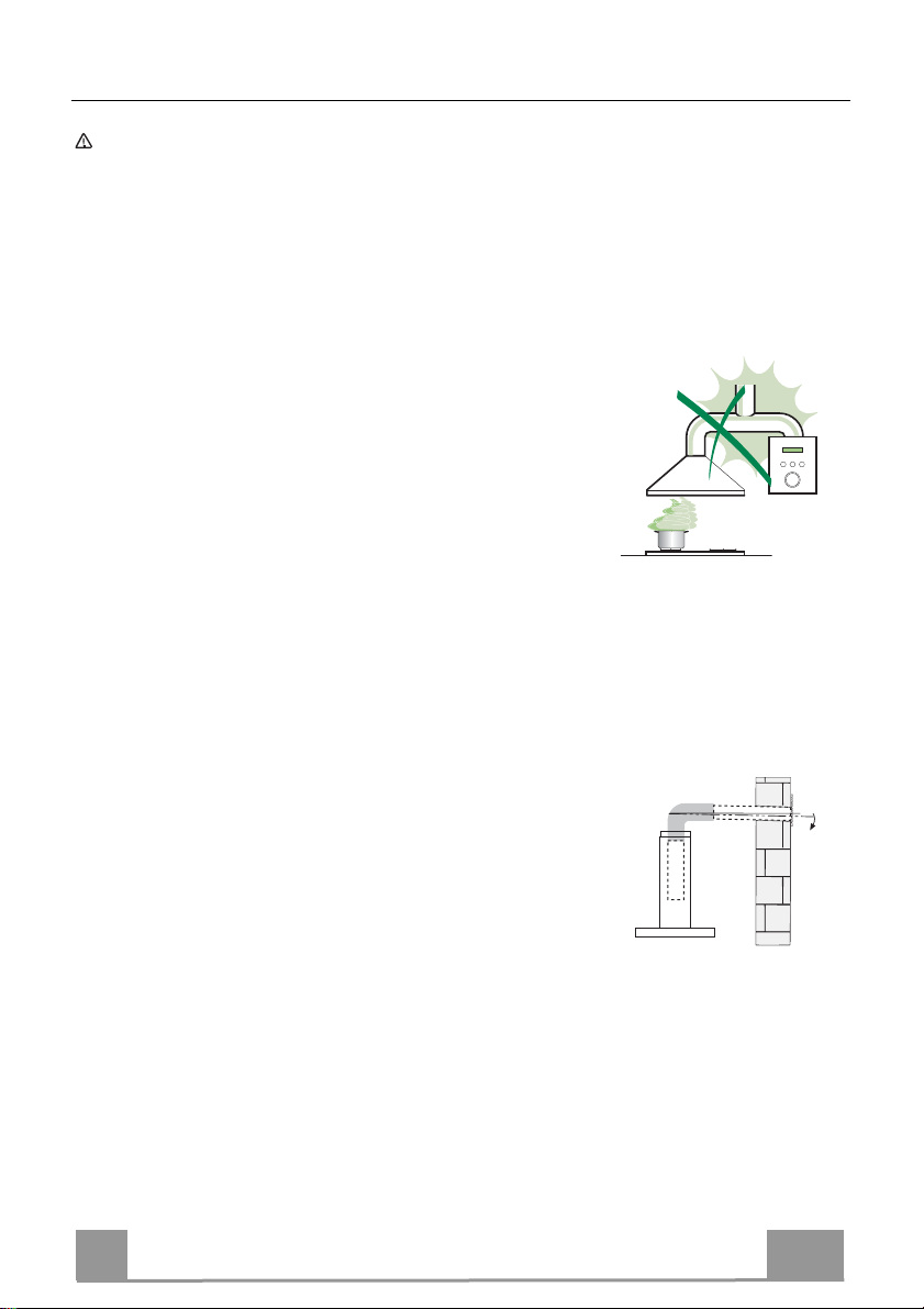
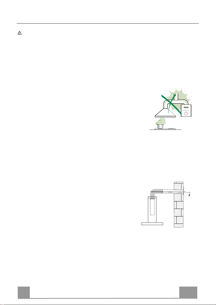
• Non collegare la cappa aspirante ai condotti fumari che trasportano fumi di
combustione (per es. caldaie, camini ecc.).
• Se l’aspiratore è utilizzato in combinazione con
apparecchi non elettrici (per es. apparecchi a gas),
deve essere garantito un sufficiente grado di
aerazione nel locale per impedire il ritorno di flusso
dei gas di scarico. La cucina deve avere un'apertura
comunicante direttamente con l'esterno per garantire
l'afflusso di aria pulita. Quando la cappa per cucina è utilizzata in
combinazione con apparecchi non alimentati dalla corrente elettrica, la
pressione negativa nel locale non deve superare 0,04 mbar per evitare che i
fumi vengano riaspirati nel locale dalla cappa.
• In caso di danneggiamento del cavo di alimentazione, occorre farlo sostituire
dal produttore o dal reparto di assistenza tecnica per evitare qualsiasi
rischio.
2°
IT
4
4

• Se le istruzioni di installazione del piano cottura a gas specificano una
distanza maggiore di quella sopra indicata, è necessario tenerne conto.
Devono essere rispettate tutte le normative riguardanti lo scarico dell'aria.
• Usare solo viti e minuteria di tipo idoneo per la cappa.
Avvertenza: la mancata installazione delle viti o dei dispositivi di fissaggio in
conformità alle presenti istruzioni può comportare rischi di scosse elettriche.
• Collegare la cappa all'alimentazione di rete mediante un interruttore bipolare
con distanza tra i contatti di almeno 3 mm.
USO
• La cappa aspirante è progettata esclusivamente per l’uso domestico allo
scopo di eliminare gli odori dalla cucina.
• Non usare mai la cappa per scopi diversi da quelli per cui è stata progettata.
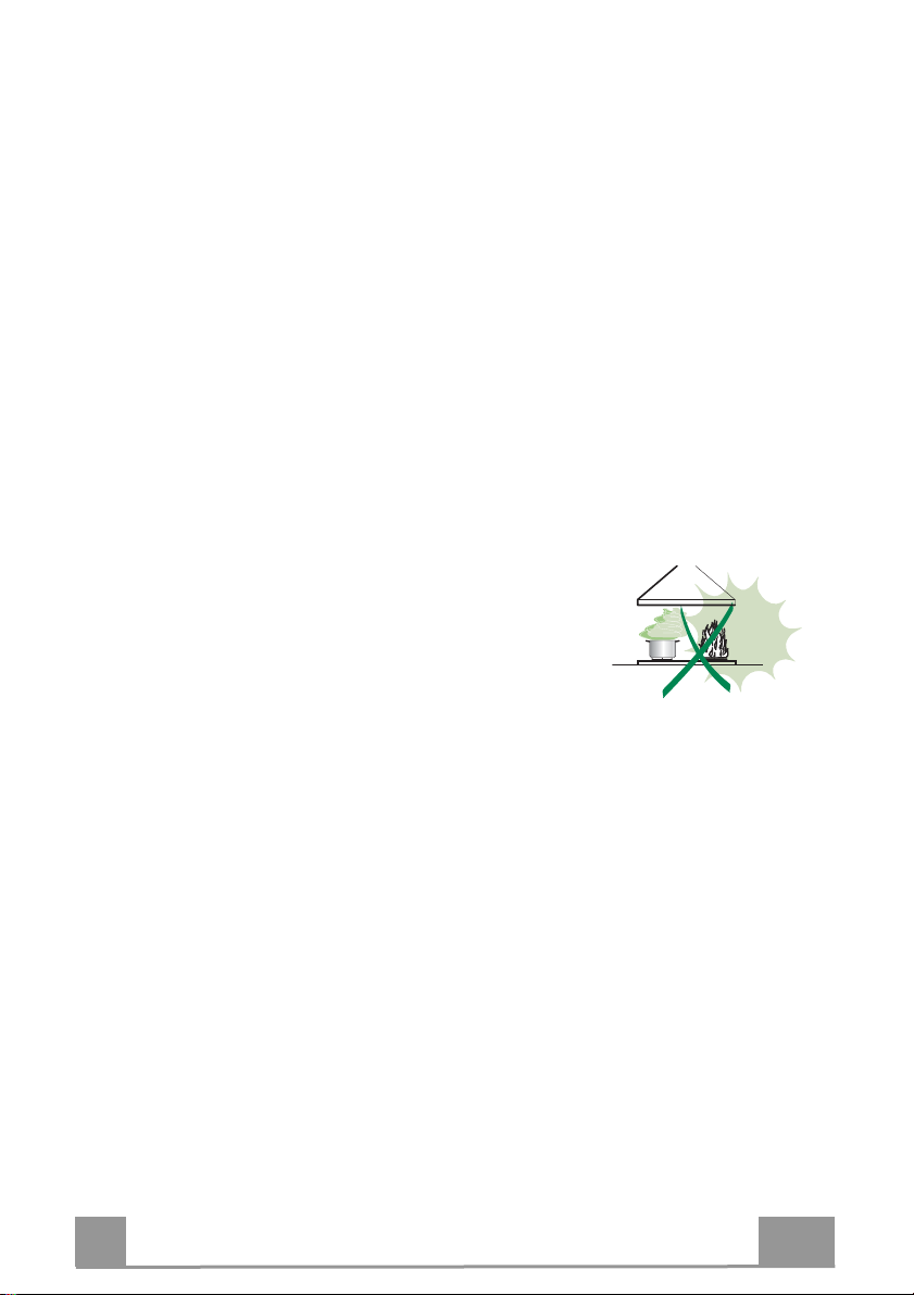
• Non lasciare mai fiamme alte sotto la cappa quando è in funzione.
• Regolare l'intensità della fiamma in modo da dirigerla esclusivamente verso
il fondo del recipiente di cottura, assicurandosi che non ne avvolga i lati.
• Le friggitrici devono essere costantemente
controllate durante l’uso: l’olio surriscaldato
potrebbe incendiarsi.
• Non cuocere al flambé sotto la cappa: si potrebbe
sviluppare un incendio.
• Questo apparecchio può essere utilizzato da
bambini di età non inferiore a 8 anni e da persone con ridotte capacità psicofisico-sensoriali o con esperienza e conoscenze insufficienti, purché
attentamente sorvegliati e istruiti su come utilizzare in modo sicuro
l'apparecchio e sui pericoli che ciò comporta. Assicurarsi che i bambini non
giochino con l'apparecchio. Pulizia e manutenzione da parte dell'utente non
devono essere effettuate da bambini, a meno che non siano sorvegliati.
IT
5
5
• “ATTENZIONE: le parti accessibili possono diventare molto calde durante
l’uso degli apparecchi di cottura”.
MANUTENZIONE
• Spegnere o scollegare l’apparecchio dalla rete di alimentazione prima di
qualunque operazione di pulizia o manutenzione.
• Pulire e/o sostituire i filtri dopo il periodo di tempo specificato (pericolo di
incendio).
• I filtri antigrasso devono essere puliti ogni 2 mesi di funzionamento o più
frequentemente in caso di utilizzo molto intenso e possono essere lavati in
lavastoviglie.
• Il filtro al carbone attivo non è lavabile né è rigenerabile e deve essere
sostituito ogni 4 mesi di funzionamento circa o più frequentemente in caso di
utilizzo molto intenso.
• Pulire la cappa utilizzando un panno umido e un detergente liquido neutro.
Il simbolo sul prodotto o sulla sua confezione indica che il prodotto non
può essere smaltito come un normale rifiuto domestico. Il prodotto da smaltire
deve essere conferito presso un apposito centro di raccolta per il riciclaggio
dei componenti elettrici ed elettronici. Assicurandosi che questo prodotto sia
smaltito correttamente, si contribuirà a prevenire potenziali conseguenze
negative per l’ambiente e per la salute che potrebbero altrimenti derivare dal
suo smaltimento inadeguato. Per informazioni più dettagliate sul riciclaggio di
questo prodotto, contattare il Comune, il servizio locale di smaltimento rifiuti
oppure il negozio dove è stato acquistato il prodotto.
IT
6
6
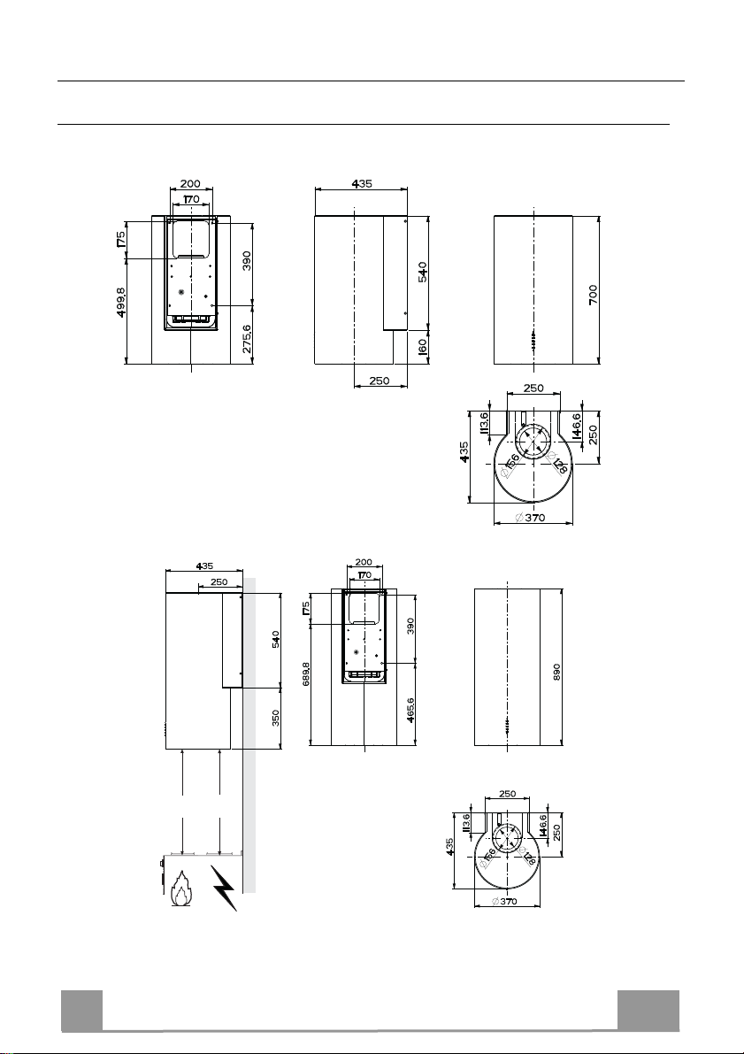
CARATTERISTICHE
Ingombro
550mm
IT
Min.
Min.
550mm
7
7
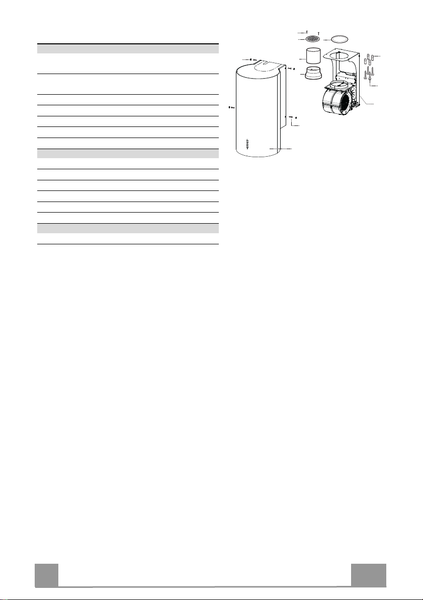
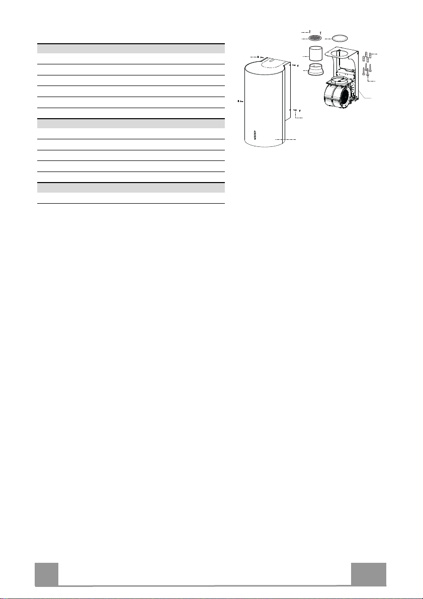
Componenti
Rif. Q.tà Componenti di Prodotto
1 1 Corpo Cappa completo di: Comandi, Luce,
Filtri
3 1 Supporto Cappa completo di Gruppo Aspirato-
re
7 1 Tubo PVC
8 1 Griglia Direzionata
8c 1 Riduzione uscita aria ø 120 mm
9 1 Flangia di riduzione ø 150-120 mm
Rif. Q.tà Componenti di Installazione
11 4 Tasselli ø 10
12a 4 Viti 5 x 70
12b 4 Viti M4 x 15
12e 2 Viti 2,9 x 9,5
13 4 Tappo viti M4
Q.tà Documentazione
1 Libretto Istruzioni
12e
8
8c
13
7
9
12b
1
11
12a
3
IT
8
8
INSTALLAZIONE
Foratura Parete
Data la complessità dell’installazione si raccomanda di effettuarla minimo in due persone.
11
12a
Nel caso di installazione della cappa in versione filtrante, tenere in considerazione che, sopra la
cappa, deve rimanere una distanza dal limite superiore (Soffitto o Mensola) di almeno 8-10 Cm.
Tracciare sulla Parete:
• una linea Verticale fino al soffitto o al limite superiore, al centro della zona prevista per il
montaggio della Cappa;
• una linea Orizzontale a: 826 mm min. sopra il Piano di Cottura;
• Segnare come indicato, un punto di riferimento a 100 mm sulla destra della linea verticale di
riferimento.
• Ripetere questa operazione dalla parte opposta, verificandone il livellamento.
• Segnare come indicato, un punto di riferimento a 390 mm sopra la linea orizzontale di riferimento, e a 100 mm sulla destra della linea verticale di riferimento.
• Ripetere questa operazione dalla parte opposta, verificandone il livellamento.
• Forare ø 10 mm i punti segnati.
• Inserire i tasselli 11 nei fori.
1050
100 100
170
175
100 100
826 390
550 mm MIN
IT
FTU 3807-P WXS 70H
9
9
Foratura Parete
Data la complessità dell’installazione si raccomanda di effettuarla minimo in due persone.
11
12a
1240
100 100
170
175
100 100
1050 390
Nel caso di installazione della cappa in versione filtrante, tenere in considerazione che, sopra la
cappa, deve rimanere una distanza dal limite superiore (Soffitto o Mensola) di almeno 8-10 Cm.
Tracciare sulla Parete:
• una linea Verticale fino al soffitto o al limite superiore, al centro della zona prevista per il
montaggio della Cappa;
• una linea Orizzontale a: 1050 mm min. sopra il Piano di Cottura;
• Segnare come indicato, un punto di riferimento a 100 mm sulla destra della linea verticale di
riferimento.
• Ripetere questa operazione dalla parte opposta, verificandone il livellamento.
• Segnare come indicato, un punto di riferimento a 390 mm sopra la linea orizzontale di riferimento, e a 100 mm sulla destra della linea verticale di riferimento.
• Ripetere questa operazione dalla parte opposta, verificandone il livellamento.
• Forare ø 10 mm i punti segnati.
• Inserire i tasselli 11 nei fori.
IT
FTU 3807-P WXS 90H
10
1

Montaggio Supporto Cappa
3
12a
ø 150
ø 120
9
8c
• Appoggiare il Supporto Cappa 3 al muro facendo coincidere i
fori del supporto con quelli fatti al muro.
• Bloccare il supporto al muro utilizzando le quattro viti 12a (5 x
70) in dotazione.
• Prima di serrare definitivamente le viti livellare il supporto,
quindi bloccare definitivamente le viti.
Connessione Uscita Aria Versione Aspirante
Per installazione in Versione Aspirante collegare la Cappa alla
tubazione di uscita per mezzo di un tubo rigido o flessibile di ø
150 o 120 mm, la cui scelta è lasciata all'installatore. Il tubo può
uscire sia dalla parte superiore che posteriore della cappa.
USCITA POSTERIORE
• Si ricorda che per effettuare il foro di evacuazione va seguito
lo schema riportato nel paragrafo foratura parete.
• Per collegamento con tubo ø120 mm, inserire la Flangia di riduzione 9 sull'Uscita del Corpo Cappa.
• Fissare il tubo con adeguate fascette stringitubo. Il materiale
occorrente non è in dotazione.
• Togliere eventuali Filtri Antiodore al Carbone attivo.
USCITA SUPERIORE
• Per collegamento con tubo ø 150 mm, collegare la Cappa alla
tubazione di uscita per mezzo di un tubo rigido o flessibile.
• Per collegamento con tubo ø120 mm, inserire la Flangia di riduzione 9 sull'Uscita del Corpo Cappa.
• Avvitare la riduzione uscita aria 8c sul foro di uscita del supporto cappa utilizzando le viti in dotazione.
• Collegare la Cappa alla tubazione di uscita per mezzo di un
tubo rigido o flessibile.
• Fissare il tubo con adeguate fascette stringitubo. Il materiale
occorrente non è in dotazione.
• Togliere eventuali Filtri Antiodore al Carbone attivo.
IT
1
11
USCITA ARIA VERSIONE FILTRANTE
• Inserire il tubo in pvc 7 in dotazione sull’uscita del Corpo
Cappa
Montaggio corpo cappa
Versione Aspirante
• Nel caso in cui sia stata scelta l’uscita dell’aria sulla parte superiore della cappa si dovrà staccare il pezzo pretagliato.
• Appoggiare il corpo cappa al supporto e fissarlo lateralmente
utilizzando le quattro viti 12b.
• Coprire le sedi delle viti impiegando i tappi 13 in dotazione.
ø 150
7
Versione Filtrante
• Staccare il pezzo pretagliato.
• Appoggiare il corpo cappa al supporto e fissarlo lateralmente
utilizzando le quattro viti 12b.
• Coprire le sedi delle viti impiegando i tappi 13 in dotazione.
• Posizionare la Griglia direzionata 8 sul Tubo e verificare la sua
corretta installazione.
• Avvitare la Griglia direzionata 8 con la Viti 12e in dotazione.
• Assicurarsi della presenza dei Filtri antiodore al Carbone attivo.
IT
12
1
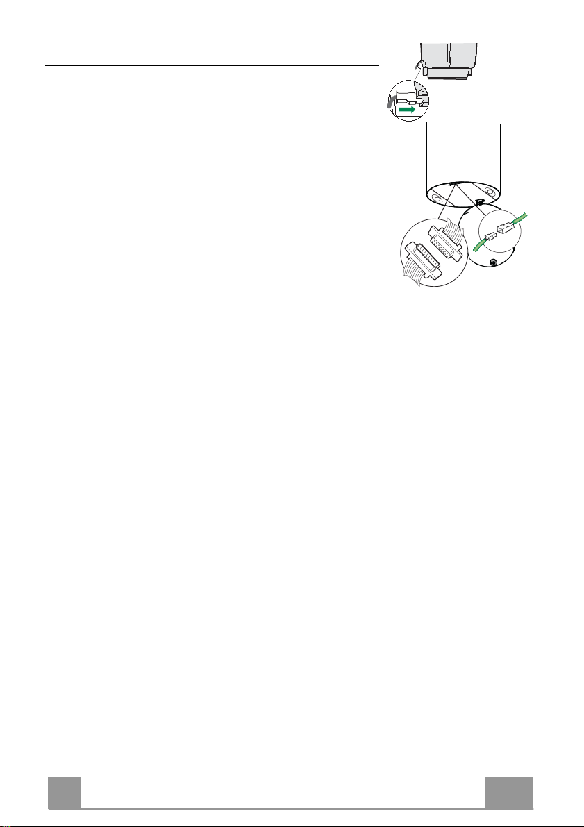
Connessione elettrica
Cmd
Lux
• Collegare la Cappa all’Alimentazione di Rete interponendo un
Interruttore bipolare con apertura dei contatti di almeno 3 mm.
• Aprire il gruppo illuminazione tirandolo sull’apposita intacca
• Togliere il Filtro , spingendolo verso la parte posteriore del
gruppo e tirando contemporaneamente verso il basso.
• Assicurarsi che il connettore del Cavo di alimentazione sia correttamente inserito nella presa dell’Aspiratore
• Collegare il connettore dei Comandi Cmd.
• Collegare il connettore dei Faretti Lux alla presa predisposta
dietro al coperchio del gruppo illuminazione.
• Rimontare il Filtro Antigrasso e successivamente il gruppo illuminazione.
IT
13
1
USO
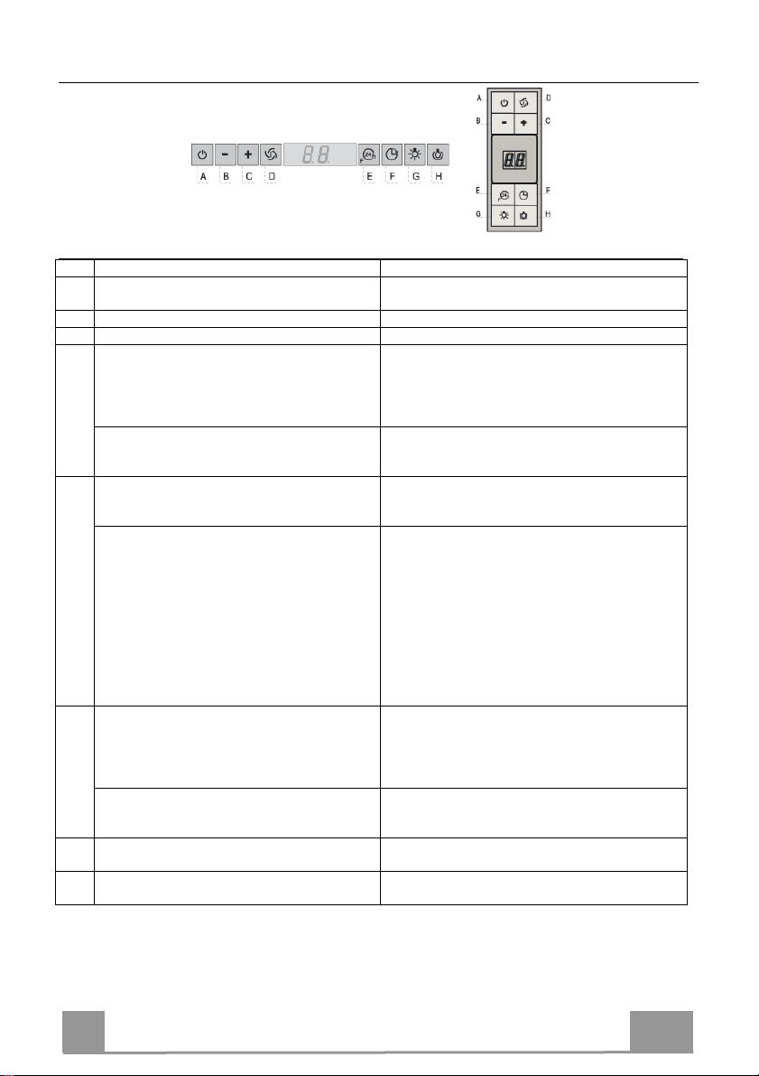
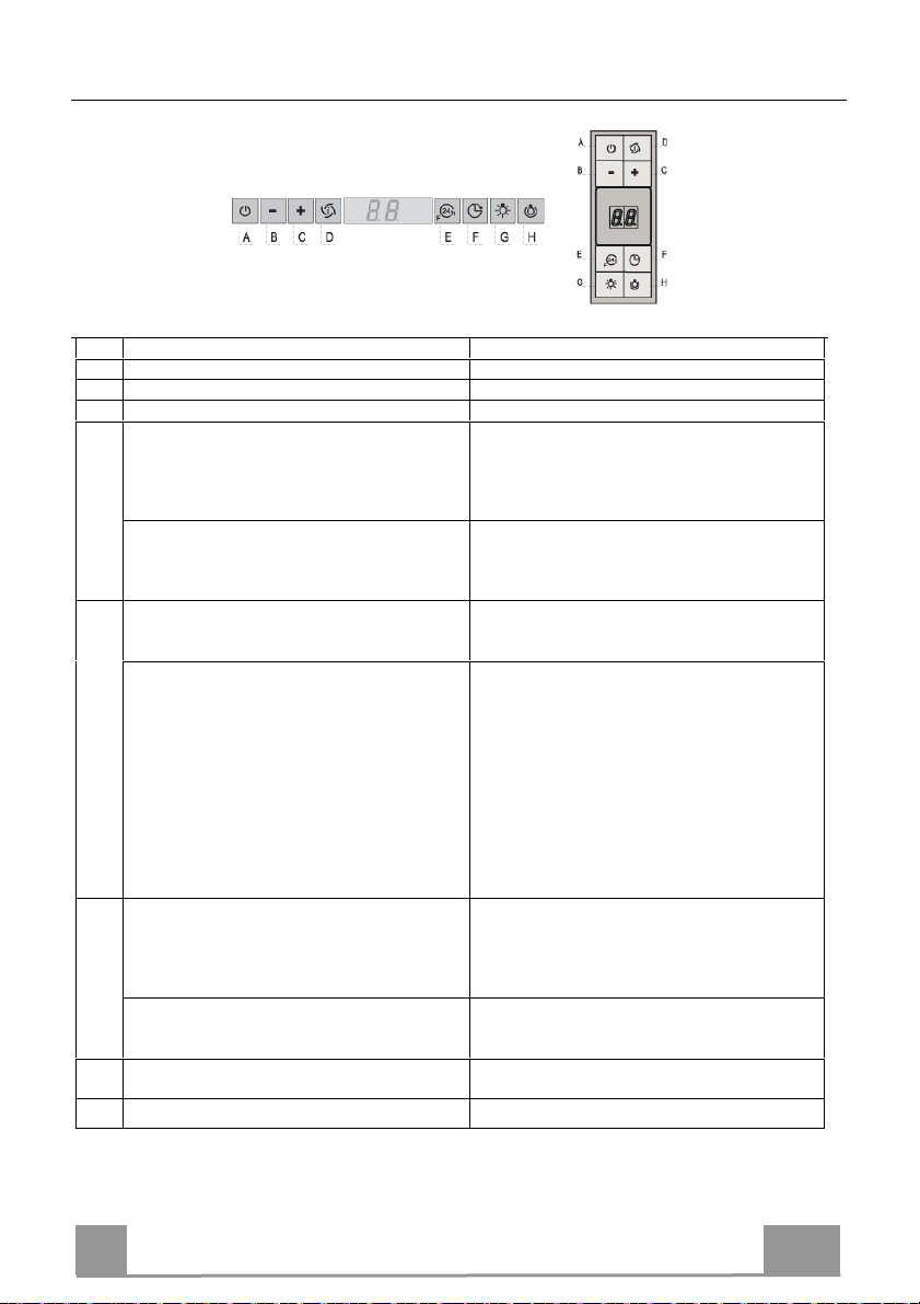
Quadro comandi
Tasto Funzione Display
A Accende e spegne il motore di aspirazione alla prima
velocità.
B Decrementa la velocità di esercizio. Visualizza la velocità impostata
C Incrementa la velocità di esercizio. Visualizza la velocità impostata
D Attiva la velocità Intensiva da qualsiasi velocità
anche da motore spento, tale velocità è temporizzata a
6 minuti, al termine del tempo il sistema ritorna alla
velocità precedentemente impostata. Adatta a fronteggiare le massime emissioni di fumi di cottura.
Tenendo il tasto premuto per circa 5 secondi, quando
tutti i carichi sono spenti (Motore+Luce), si Attiva /
Disattiva l’allarme dei Filtri al Carbone attivo.
E Funzione 24H
Attiva il motore alla prima velocità e consente
un’aspirazione di 10 minuti ogni ora.
Con l’allarme filtri in corso premendo il tasto per
circa 3 secondi si effettua il reset dell’allarme.
Tali segnalazioni sono visibili solo a motore spento.
F Funzione Delay
Attiva lo spegnimento automatico ritardato di 30’.
Adatto per completare l’eliminazione di odori residui.
Attivabile da qualsiasi posizione, si disattiva premendo il tasto o spegnendo il motore.
Tenendo il tasto premuto per circa 5 secondi, quando
tutti i carichi sono spenti (Motore+Luce), si Attiva /
Disattiva il Telecomando.
G Accende e spegne l’impianto di illuminazione alla
massima intensità.
H Accende e spegne l’impianto di illuminazione in
modalità Luce di Cortesia.
Visualizza la velocità impostata
Visualizza alternamente HI e il tempo rimanente una
volta al secondo.
FC+Punto (2Lampeggi)–Allarme Attivo.
FC+Punto (1Lampeggio)–Allarme Disattivo.
Visualizza 24 e il punto in basso a destra lampeggia una
volta al secondo, mentre il motore è in funzione.
Si disabilita premendo il tasto.
Lampeggia FF tre volte.
Terminata la procedura si spegne la segnalazione precedentemente visualizzata:
FG segnala la necessità di lavare i filtri antigrasso metallici. L’allarme entra in funzione dopo 100 ore di lavoro
effettivo della Cappa.
FC segnala la necessità di sostituire i filtri al carbone
attivo e devono anche essere lavati i filtri antigrasso metallici. L’allarme entra in funzione dopo 200 ore di lavoro
effettivo della Cappa.
Visualizza la velocità di esercizio e il punto in basso a
destra lampeggia una volta al secondo.
IR+Punto (2Lampeggi)–Allarme Attivo.
IR+Punto (1Lampeggio)–Allarme Disattivo.
IT
14
1
MANUTENZIONE
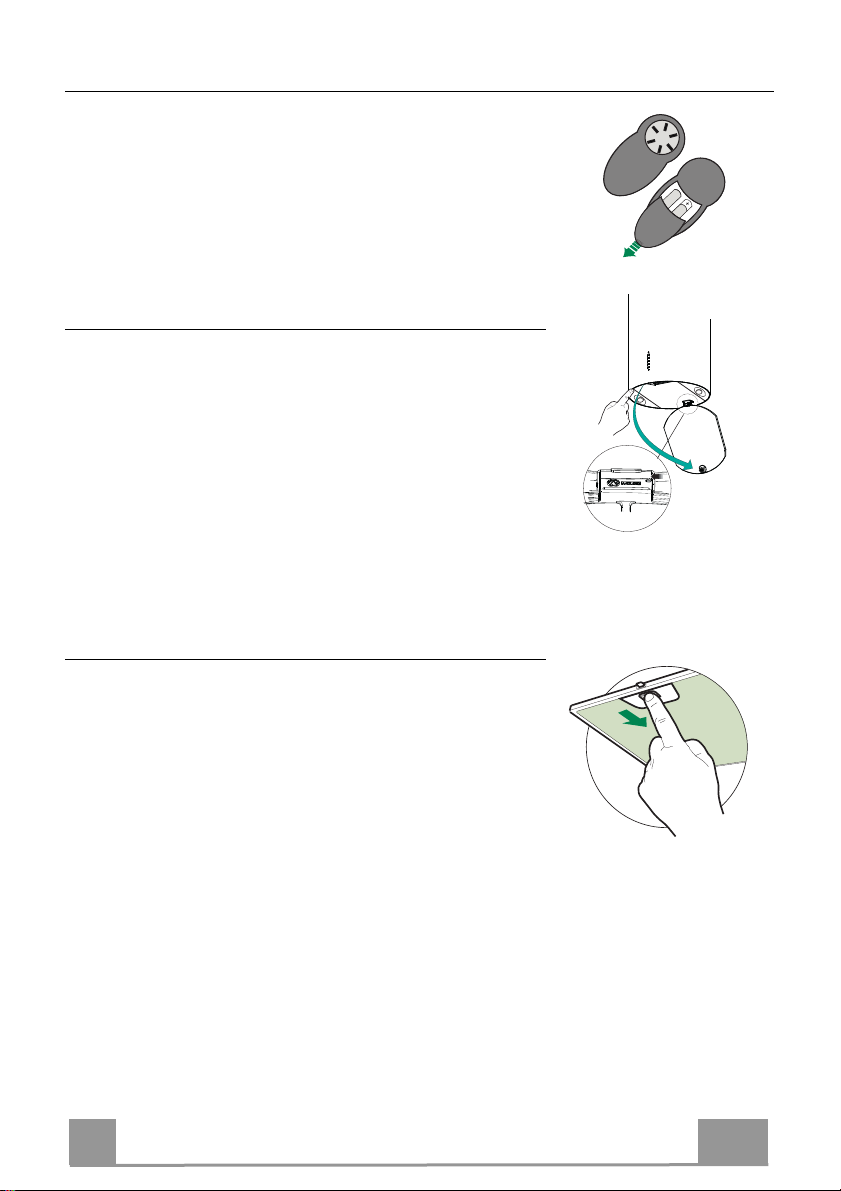
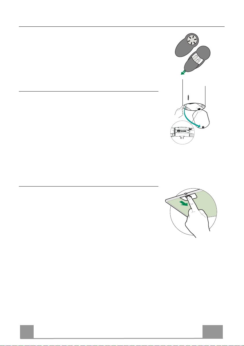
TELECOMANDO (OPZIONALE)
Questo apparecchio può essere comandato per mezzo di un telecomando, alimentato con pile alcaline zinco-carbone da 1,5 V del
tipo standard LR03-AAA (non incluse).
• Non riporre il telecomando in prossimità di fonti di calore.
• Non disperdere le pile nell’ambiente, depositarle negli appositi
contenitori.
Pulizia dei Comfort Panel
• Aprire il Comfort Panel tirandolo.
• Sganciare il pannello dal corpo cappa facendo scorrere
l’apposita leva del perno di fissaggio.
• Il comfort panel non va assolutamente lavato in lavastoviglie.
• Pulirlo esternamente con un panno umido e detersivo liquido
neutro.
• Pulirlo anche internamente utilizzando un panno umido e detergente neutro; non utilizzare panni o spugne bagnate, né getti
d’acqua; non utilizzare sostanze abrasive.
• Ad operazione ultimata riagganciare il pannello al corpo cappa
e richiuderlo.
Filtri antigrasso metallici
Sono lavabili anche in lavastoviglie, e necessitano di essere lavati
quando sul display appare FG o almeno ogni 2 mesi circa di utilizzo o più frequentemente, per un uso particolarmente intenso.
Reset del segnale di allarme
• Spegnere le Luci e il Motore di aspirazione, quindi qualora
fosse attivata la funzione 24h disattivarla.
• Premere il tasto E (Vedi paragrafo Uso).
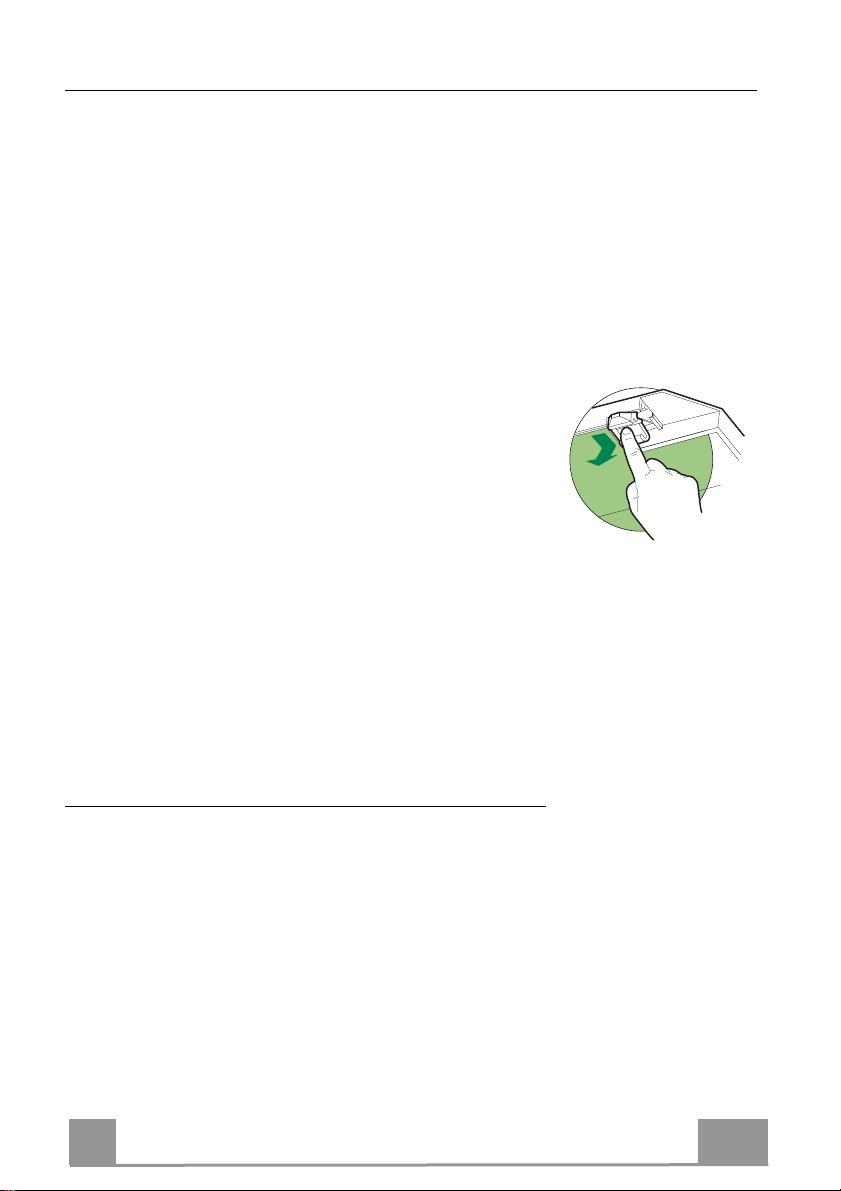
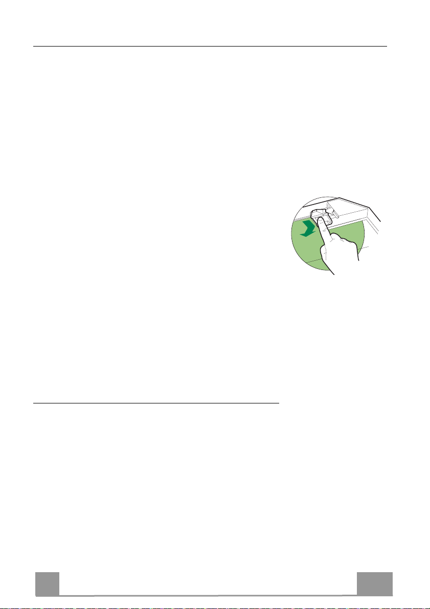
Pulizia Filtri
• Aprire i Confort Panel tirandolo sull’apposita intacca.
• Togliere i Filtri uno alla volta, spingendoli verso la parte posteriore del gruppo e tirando contemporaneamente verso il basso.
• Lavare i Filtri evitando di piegarli, e lasciarli asciugare prima
di rimontarli. (Un’eventuale cambiamento del colore della superficie del filtro, che potrebbe verificarsi nel tempo, non pregiudica assolutamente l’efficienza dello stesso.)
• Rimontarli facendo attenzione a mantenere la maniglia verso la
parte visibile esterna.
• Richiudere i Confort Panel.
IT
15
1
Filtri antiodore al Carbone attivo (Versione Filtrante)
Non è lavabile e non è rigenerabile, va sostituito quando sul display appare FC o almeno ogni
4 mesi. La segnalazione di Allarme, se preventivamente attivata, si verifica solo quando è azionato il Motore di aspirazione.
Attivazione del segnale di allarme
• Nelle Cappe in Versione Filtrante, la segnalazione di Allarme saturazione Filtri va attivata al
momento dell’installazione o successivamente.
• Spegnere le Luci e il Motore di aspirazione.
• Premere il tasto D per circa 5 Secondi:
• 2 Lampeggi scritta FC+Puntino -- Allarme saturazione Filtro C.A. ATTIVATO.
• 1 Lampeggio scritta FC+Puntino -- Allarme saturazione Filtro C.A. DISATTIVATO.
SOSTITUZIONE FILTRO ANTIODORE AL CARBONE ATTIVO
Reset del segnale di allarme
• Spegnere le Luci e il Motore di aspirazione, quindi qualora
fosse attivata la funzione 24h disattivarla.
• Premere il tasto E (Vedi paragrafo Uso).
Sostituzione Filtro
• Aprire i Confort Panel tirandolo sull’apposita intacca.
• Togliere i Filtri antigrasso metallici.
• Rimuovere il Filtro antiodore al Carbone attivo saturo, agendo
sugli appositi agganci.
• Montare il nuovo Filtro agganciandolo nella sua sede.
• Rimontare i Filtri antigrasso metallici.
• Richiudere i Confort Panel.
Illuminazione
Attenzione: Questo apparecchio è provvisto di una luce LED
bianca di classe 1M secondo la norma EN 60825-1: 1994 +
A1:2002 + A2:2001; massima potenza ottica emessa@439nm:
7µW. Non osservare direttamente con strumenti ottici (binocolo,
lente d’ingrandimento….).
• Per la sostituzione contattare l’Assistenza Tecnica. ("Per l'acquisto rivolgersi all'assistenza tecnica").
IT
1
16
RECOMMENDATIONS AND SUGGESTIONS
The Instructions for Use apply to several versions of this appliance.
Accordingly, you may find descriptions of individual features that do not
apply to your specific appliance.
INSTALLATION
• The manufacturer will not be held liable for any damages resulting from
incorrect or improper installation.
• The minimum safety distance between the cooker top
and the extractor hood is 650 mm (some models can
be installed at a lower height, please refer to the
paragraphs on working dimensions and installation).
• Check that the mains voltage corresponds to that
indicated on the rating plate fixed to the inside of the
hood.
• For Class I appliances, check that the domestic
power supply guarantees adequate earthing.
Connect the extractor to the exhaust flue through a pipe of minimum
diameter 120 mm. The route of the flue must be as short as possible.
• Do not connect the extractor hood to exhaust ducts carrying combustion
fumes (boilers, fireplaces, etc.).
• If the extractor is used in conjunction with nonelectrical appliances (e.g. gas burning
appliances), a sufficient degree of aeration must
be guaranteed in the room in order to prevent the
backflow of exhaust gas. The kitchen must have
an opening communicating directly with the open
air in order to guarantee the entry of clean air.
When the cooker hood is used in conjunction with
appliances supplied with energy other than electric, the negative pressure in
the room must not exceed 0,04 mbar to prevent fumes being drawn back
into the room by the cooker hood.
• In the event of damage to the power cable, it must be replaced by the
manufacturer or by the technical service department, in order to prevent any
risks.
2°
EN
17
1
• If the instructions for installation for the gas hob specify a greater distance
specified above, this has to be taken into account. Regulations concerning
the discharge of air have to be fulfilled.
• Use only screws and small parts in support of the hood.
Warning: Failure to install the screws or fixing device in accordance with
these instructions may result in electrical hazards.
• Connect the hood to the mains through a two-pole switch having a contact
gap of at least 3 mm.
USE
• The extractor hood has been designed exclusively for domestic use to
eliminate kitchen smells.
• Never use the hood for purposes other than for which it has been designed.
• Never leave high naked flames under the hood when it is in operation.
• Adjust the flame intensity to direct it onto the bottom of the pan only, making
sure that it does not engulf the sides.
• Deep fat fryers must be continuously monitored
during use: overheated oil can burst into flames.
• Do not flambè under the range hood; risk of fire.
• This appliance can be used by children aged from
8 years and above and persons with reduced
physical, sensory or mental capabilities or lack of
experience and knowledge if they have been given supervision or instruction
concerning use of the appliance in a safe way and understand the hazards
involved. Children shall not play with the appliance. Cleaning and user
maintenance shall not be made by children without supervision.
EN
18
1
• “CAUTION: Accessible parts may become hot when used with cooking
appliances.”
MAINTENANCE
• Switch off or unplug the appliance from the mains supply before carrying out
any maintenance work.
• Clean and/or replace the Filters after the specified time period (Fire hazard).
• The Grease filters must be cleaned every 2 months of operation, or more
frequently for particularly heavy usage, and can be washed in a dishwasher.
• The Activated charcoal filter is not washable and cannot be regenerated,
and must be replaced approximately every 4 months of operation, or more
frequently for particularly heavy usage.
• Clean the hood using a damp cloth and a neutral liquid detergent.
The symbol on the product or on its packaging indicates that this product
may not be treated as household waste. Instead it shall be handed over to the
applicable collection point for the recycling of electrical and electronic
equipment. By ensuring this product is disposed of correctly, you will help
prevent potential negative consequences for the environment and human
health, which could otherwise be caused by inappropriate waste handling of
this product. For more detailed information about recycling of this product,
please contact your local city office, your household waste disposal service or
the shop where you purchased the product.
EN
19
1
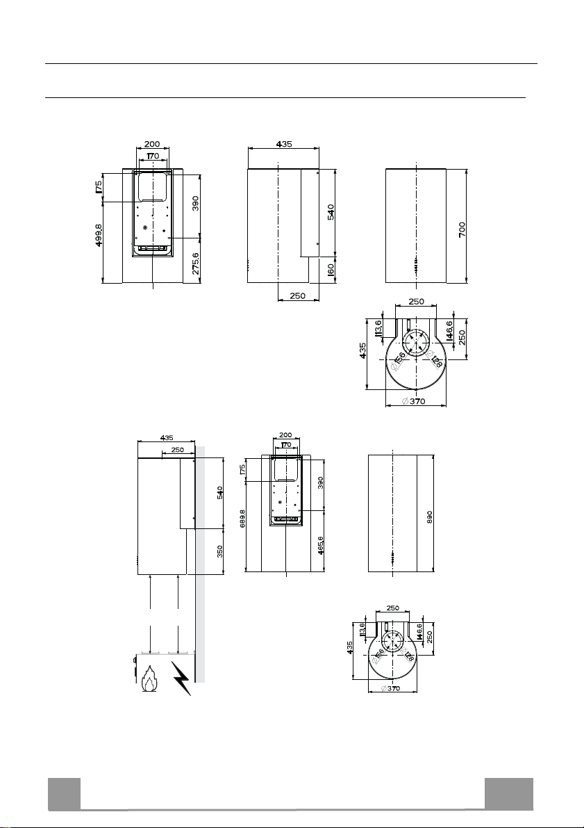
CHARACTERISTICS
Dimensions
EN
Min.
550mm
Min.
550mm
20
2
Components
Ref. Q.ty Product components
1 1 Hood equipped with: Controls, Lights, Filters
3 1 Hood support equipped with the Exhaust Group
7 1 tube in PVC
8 1 Directioned grid
8c 1 Air outlet reduction ø 120mm
9 1 Reduction flange ø 150-120 mm
Ref. Q.ty Installation components
11 4 Small blocks ø 10
12a 4 Screws 5 x 70
12b 4 Screws M4 x 15
12e 2 Screws 2,9 x 9,5
13 4 Screws plug M4
Q.ty Documentations
1 Instruction booklet
12e
8
8c
13
7
9
12b
1
11
12a
3
EN
21
2
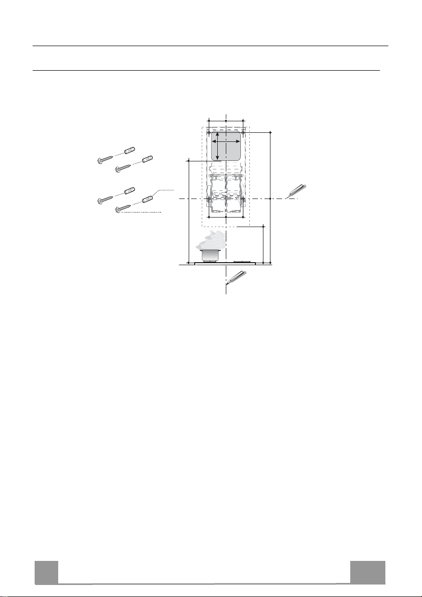
INSTALLATION
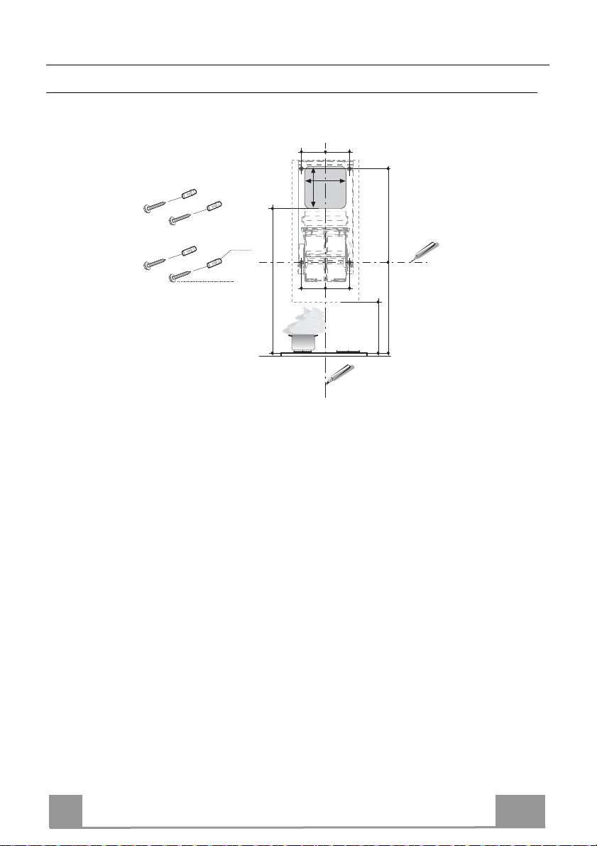
Wall drilling and bracket fixing
Due to the complexity in installing the hood, we suggest to do it minimum in two people
11
12a
When installing the hood in recycling version it has to be taken into consideration that space remaining between the hood and the upper limit (ceiling or self) is at least 8-10 cm.
On the wall, draw:
• a Vertical line up to the ceiling or upper limit, at the centre of the area in which the hood is
to be fitted;
• a Horizontal line at a minimum of 826 mm above the Cooker Top; .
• As indicated, mark a reference point at 100 mm to the right of the vertical reference line.
• Repeat this operation on the other side, checking that the two marks are level.
• As indicated, mark a reference point at 390 mm above the horizontal reference line, and at
100 mm to the right of the vertical reference line.
• Repeat this operation on the other side, checking that the two marks are level.
• Drill at the points marked, using a ø 10 mm drill bit.
• Insert the plugs 11 into the holes.
1050
100 100
170
175
100 100
826 390
550 mm MIN
EN
FTU 3807-P WXS 70H
22
2
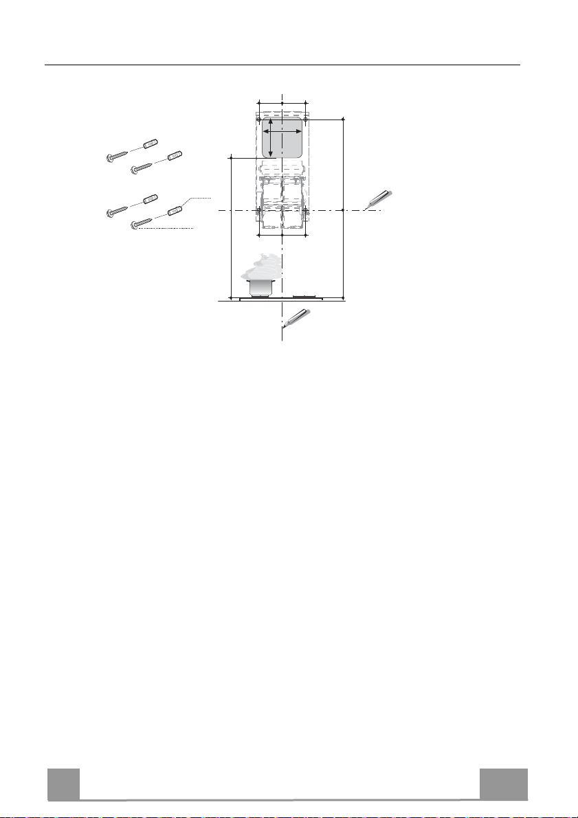
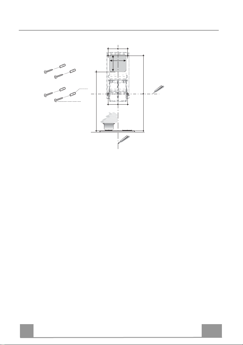
Wall drilling and bracket fixing
100 100
170
175
12a
11
1240
100 100
1050 390
When installing the hood in recycling version it has to be taken into consideration that space remaining between the hood and the upper limit (ceiling or self) is at least 8-10 cm.
On the wall, draw:
• a Vertical line up to the ceiling or upper limit, at the centre of the area in which the hood is
to be fitted;
• a Horizontal line at a minimum of 1050 mm above the Cooker Top; .
• As indicated, mark a reference point at 100 mm to the right of the vertical reference line.
• Repeat this operation on the other side, checking that the two marks are level.
• As indicated, mark a reference point at 390 mm above the horizontal reference line, and at
100 mm to the right of the vertical reference line.
• Repeat this operation on the other side, checking that the two marks are level.
• Drill at the points marked, using a ø 10 mm drill bit.
• Insert the plugs 11 into the holes.
EN
FTU 3807-P WXS 90H
23
2
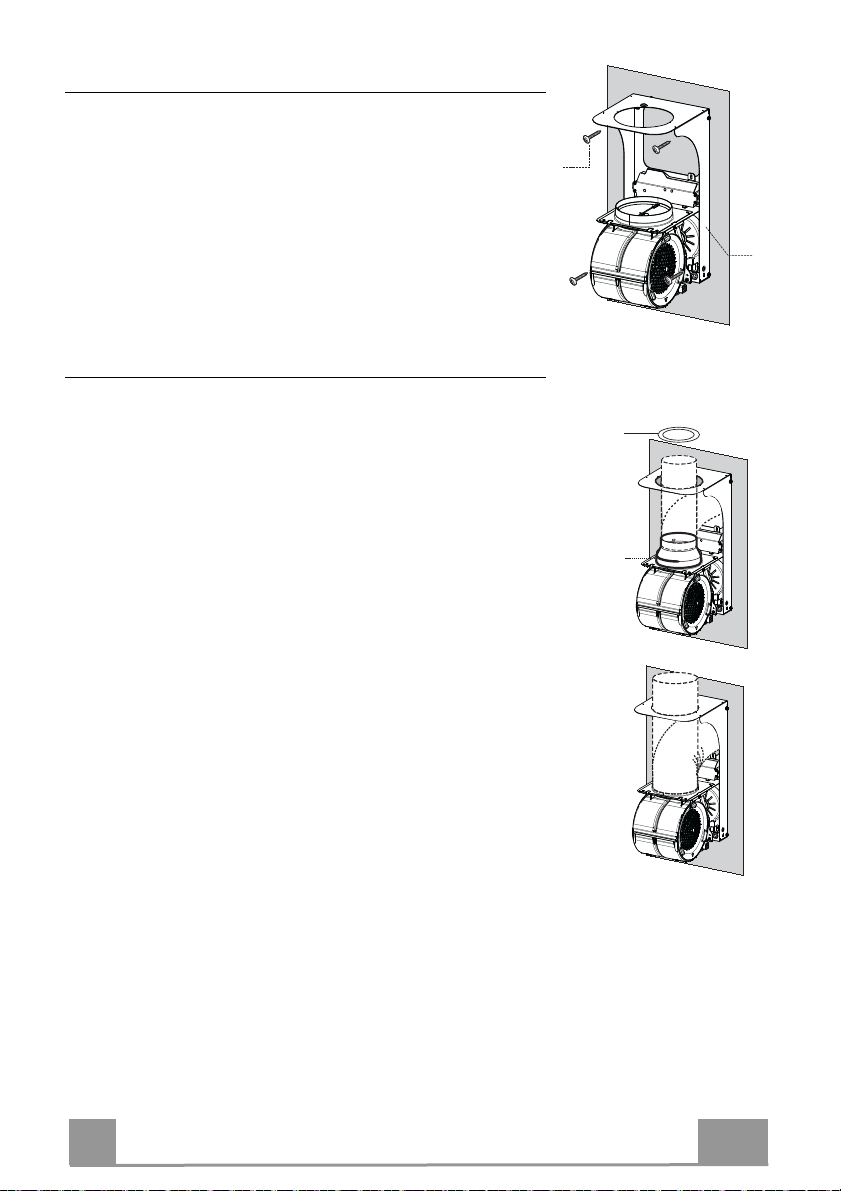
Hood support mounting
3
12a
ø 150
ø 120
9
8c
• Lean the hood support 3 against the wall making sure that
holes in the hood support correspond to those in the wall.
• Block the hood support to the wall using 4 12a (5 x 70) screws
supplied with the hood.
• Before fastening the screws definitively make sure that the
support is well-levelled. Only after this operation proceed with
the definitive tightening of the screws.
Air outlet connection in the ducting version
When installing the hood in ducting version, basing on the installer’s choice, a rigid or a flexible pipe with a ø 150 o 120 mm
is used in order to connect the hood to the air outlet piping. The
pipe connection can be made on the upper part or on the back
side of the hood.
AIR OUTLET ON THE BACK SIDE OF THE HOOD
• When drilling the air outlet hole in the wall proceed in accordance with the scheme in the paragraph concerning the wall
drilling.
• In case the connection is made with a ø 120 mm pipe insert the
reduction flange 9 on the hood body outlet.
• Fix the pipe with an adequate quantity of pipe clamps. This
material is not supplied together with the hood.
• Remove the charcoal filter if present.
AIR OUTLET ON THE UPPER PART OF THE HOOD
• In case the connection of the hood to the air outlet piping is
made with a ø 150 mm pipe then use a rigid or a flexible pipe.
• In case the connection is made with a ø 120 mm pipe insert the
reduction flange 9 on the hood body outlet.
• Fix the air outlet reduction 8c to the air outlet hole of the hood
support with the screws supplied together with the hood.
• Connect the hood to the piping with a rigid or a flexible pipe.
• Fix the pipe with an adequate quantity of pipe clamps. This
material is not supplied together with the hood.
• Remove the charcoal filter if present.
EN
2
24

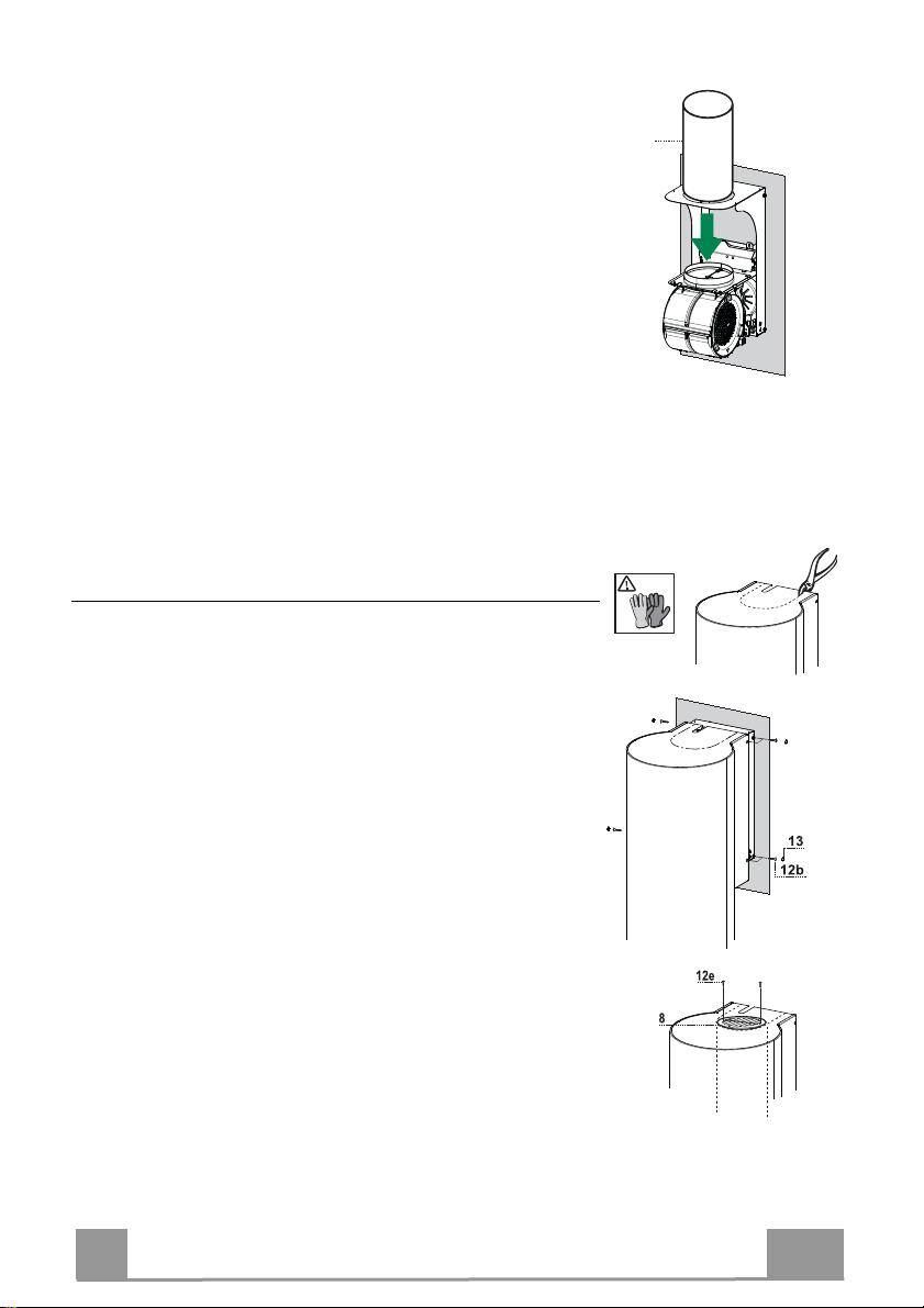
RECIRCULATION VERSION AIR OUTLET
• Insert pvc pipe 7 provided onto the Hood Canopy Outlet.
Hood body mounting
Ducting version
• In case the air outlet connection on the upper part of the hood
has been chosen it will be necessary to remove the pre-cut
piece.
• Lean the hood body on the support and fix it laterally with the
4 12b screws.
• Cover the screw seats with the plugs 13 supplied with the
hood.
ø 150
7
Recycling version
• Remove the pre-cut piece.
• Lean the hood body on the support and fix it laterally with the
4 12b screws.
• Cover the screw seats with the plugs 13 supplied with the
hood.
• Place the directioned grid 8 on the pipe and make sure that it is
correctly installed.
• Fix the directioned grid 8 with the screws 12e supplied together with the hood.
• Make sure that the charcoal filters are present.
EN
25
2

ELECTRICAL CONNECTION
Cmd
Lux
• Connect the hood to the mains through a twopole
switch having a contact gap of at least 3 mm.
• Open the lighting unit by pulling on the notch.
• Remove the filters one at a time by pushing them towards the
back of the group and pulling down at the same time.
• Being sure that the connector of the feeding cable is correctly
inserted in the socket placed on the side of the fan.
• Connect the control connector Cmd.
• Connect the Spotlights connector Lux to the socket provided
behind the lighting unit cover.
• Replace the filters, make sure that the handle is visible on the
outside, and the lighting unit.
EN
26
2
USE
Control panel
Button Function Display
A Turns the suction motor on and off at speed one. Displays the set speed
B Decreases the working speed. Displays the set speed
C Increases the working speed. Displays the set speed
D Activate intensive speed from any other speed,
including motor off. This speed is set to operate for 6
minutes, after which the system returns to the speed
that was set before. Suitable to deal with maximum
levels of cooking fumes.
Press and hold the button for approximately 5
seconds, with all the loads turned off (Motor and
Lights), to turn the Activated Charcoal Filter alarm
On and Off.
E 24H function
Turns the suction motor on at speed one and effects
one 10 minute extraction every hour.
When the filters alarm is triggered, the alarm can be
reset by pressing and holding this button for
approximately 3 seconds.
These indications are only visible when the motor is
turned off.
F Delay function
Activate automatic switch-off with a 30’ delay.
Suitable to complete elimination of residual odours.
Can be activated from any position, and is disabled
by pressing the button or turning the motor off.
Press and hold the button for approximately 5
seconds, with all the loads turned off (Motor and
Lights), to turn the Remote Control On and Off.
G Turns the lighting system on and off at maximum
intensity.
H Turns the Courtesy Lighting on and off.
Displays HI and the time remaining once very second.
FC+Punto (2 flashes)–Alarm On.
FC+Punto (1 flash)–Alarm Off.
Displays 24 and the spot at the bottom right flashes
once every second, while the motor is running.
It is disabled by pressing the button.
FF flashes three times.
When the procedure terminates, the indication shown
previously turns off:
FG indicates the need to wash the metal grease
filters. The alarm is triggered after the Hood has been
in operation for 100 working hours.
FC indicates the need to change the activated
charcoal filters, and also to wash the metal grease
filters. The alarm is triggered after the Hood has been
in operation for 200 working hours.
Displays the operating speed and the spot at the bottom
right flashes once a second.
IR+Punto (2 flashes)–Alarm On.
IR+Punto (1 flash)–Alarm Off.
EN
27
2
MAINTENANCE
REMOTE CONTROL (OPTIONAL)
The appliance can be controlled using a remote control powered
by a 1.5 V carbon-zinc alkaline batteries of the standard LR03AAA type (not included).
• Do not place the remote control near to heat sources.
• Used batteries must be disposed of in the proper manner.
Cleaning the Comfort Panels
• Pull the Comfort Panel to open it.
• Disconnect the panel from the hood canopy by sliding the fixing pin lever.
• The comfort panel must never be washed in a dishwasher.
• Clean the outside by using a damp cloth and neutral liquid detergent.
• Clean the inside as well by using a damp cloth and neutral detergent; do not use wet cloths or sponges, or jets of water; do
not use abrasive substances.
• When the above operation has been completed, hook the panel
back to the hood canopy and close it by turning the knob in the
opposite direction.
Metal grease filters
They can be washed in the dishwasher, and need to be cleaned
whenever the FG sign appears on the display or at least once
every 2 months use, or more frequently if use is particularly
intensive.
Resetting the alarm signal
• Turn the Lights and the Suction motor off, then disable the 24h
function, if enabled.
• Press button E (see the paragraph on Use).
Cleaning the Filters
• Open the Comfort panels by pulling on the recess.
• Remove the Filters one at a time, pushing them towards the
back of the unit and at the same time pulling downward.
• Wash the Filters without bending them, and leave them to dry
completely before replacing. (If the surface of the filter
changes colour as time goes by, this will have absolutely no
effect on the efficiency of the filter itself.)
• Replace, taking care to ensure that the handle faces forwards.
• Close the Comfort panels.
EN
28
2
Activated Charcoal Filter (Recirculation Version)
It cannot be washed or regenerated, and must be changed when the FC symbol on the display
appears, or at least once every 4 months. The Alarm signal, if it has been activated, only
appears when the Suction motor is turned on.
Activating the alarm signal
• In Recirculation Version Hoods, the Filter Saturation Alarm must be activated on
installation or at a later date.
• Turn the Lights and the Suction Motor off.
• Press D and hold for approximately 5 Seconds:
• The message FC+Puntino flashes twice, A.C. Filter saturation alarm ACTIVATED
• The message FC+Puntino flashes once, A.C. Filter saturation alarm DEACTIVATED
CHANGING THE ACTIVATED CHARCOAL FILTER
Resetting the alarm signal
• Turn the Lights and the Suction motor off, then disable the 24h
function, if enabled.
• Press button E (see the paragraph on Use).
Changing the Filter
• Open the Comfort panels by pulling on the recess.
• Remove the Metal grease filters.
• Remove the saturated charcoal filter by releasing the fixing
hooks.
• Fit the new filter and fasten it in its correct position.
• Replace the Metal grease filters.
• Close the Comfort panels.
Lighting unit
Warning: This appliance is fitted with a white LED lamp classed
as 1M according to EN 60825-1: 1994 + A1:2002 + A2:2001
standards; maximum optical power emitted @439nm: 7µW. Do
not look directly at the light through optical devices (binoculars,
magnifying glasses…).
• For replacement contact technical support. ("To purchase contact technical support")
EN
2
29
 Loading...