

Page 1

Istruzioni per l’uso e l’installazione
Cappa
Instructions for use and installation
Cooker Hood
Mode d’emploi et installation
Hotte de Cuisine
Bedienungsanleitung und Einrichtung
Dunstabzugshaube
Kullan
ım ve montaj talimatları
Davlumbaz
FTF 604
FTF 904
FTF 6042
FTF 9042
IT
GB
FR
DE
TR
Page 2

IT
2
2
Libretto di Istruzioni
INDICE
GENERALITÀ – AVVERTENZE PER LA SICUREZZA......................................................................................................... 7
INSTALLAZIONE ...................................................................................................................................................................8
USO........................................................................................................................................................................................ 9
MANUTENZIONE................................................................................................................................................................. 10
Page 3

EN
3
3
Instructions Manual
INDEX
GENERAL INFORMATION - SAFETY WARNINGS...........................................................................................................11
INSTALLATION....................................................................................................................................................................12
USE...................................................................................................................................................................................... 13
MAINTENANCE...................................................................................................................................................................14
Page 4

FR
4
4
Manuel d’Instructions
SOMMAIRE
GENERALITES - CONSEILS CONCERNANT LA SECURITE ..................................................... 15
INSTALLATION............................................................................................................................ 16
UTILISATION ............................................................................................................................... 17
ENTRETIEN................................................................................................................................. 18
Page 5

DE
5
5
Bedienungsanleitung
INHALTSVERZEICHNIS
ALLGEMEINES - SICHERHEITSHINWEISE................................................................................ 19
MONTAGE................................................................................................................................... 20
BEDIENUNG................................................................................................................................ 21
WARTUNG................................................................................................................................... 22
Page 6

TR
6
6
Kullanim Kilavuku
IÇERIKLER
GENEL BĐLGĐLER - GÜVENLĐK UYARILARI......................................................................................................................23
MONTAJ............................................................................................................................................................................... 24
KULLANIM ...........................................................................................................................................................................25
BAKIM ..................................................................................................................................................................................26
Page 7

IT
7
7
GENERALITÀ – AVVERTENZE PER LA SICUREZZA
GENERALITÀ
Questa cappa è predisposta per essere installata a muro, sopra un piano di cottura posizionato a ridosso di una parete.
Può essere utilizzata in versione aspirante (evacuazione esterna), oppure in versione filtrante (riciclo interno). Le migliori prestazioni si ottengono nella versione aspirante: tuttavia nel periodo invernale può
essere conveniente utilizzare la cappa in versione filtrante per evitare dispersioni di calore.
Si raccomanda che l’installazione venga effettuata da personale specializzato, rispettando tutte
le prescrizioni delle autorità competenti relative allo scarico dell’aria da evacuare.
Il produttore declina qualsiasi responsabilità per danni dovuti ad installazione non corretta o non
conforme alle regole dell’arte.
1 - AVVERTENZE PER LA SICUREZZA
1.1 - Non collegare la cappa a condotti di scarico dei fumi prodotti da combustione (caldaie, caminetti, ecc...).
1.2 - Verificare che la tensione di rete corrisponda a quella riportata nella targhetta posta all’interno
della cappa.
1.3 - Collegare la cappa alla rete interponendo un interruttore bipolare con apertura dei contatti di
almeno 3 mm.
1.4 - Per cappe provviste di terra, accertarsi che l’impianto elettrico domestico garantisca un corretto
funzionamento.
1.5 - Le cappe in classe II hanno il doppio isolamento; non devono essere collegate con una spina
con messa a terra, ma vanno collegate con una semplice spina bipolare.
1.6 - La distanza minima di sicurezza tra il piano di cottura e la cappa è di 65 cm.
1.7 - Non fare cucine alla fiamma sotto la cappa.
1.8 - Controllare le friggitrici durante l’uso: l’olio surriscaldato potrebbe infiammarsi.
1.9 - Prima di procedere a qualsiasi operazione di pulizia o di manutenzione, disinserire l’apparecchio
togliendo la spina o agendo sull’interruttore generale.
1.10- Nel caso in cui nella stanza vengano utilizzati sia la cappa che apparecchi non azionati da energia elettrica (ad esempio apparecchi utilizzatori a gas), si deve provvedere ad una aerazione sufficiente dell’ambiente. Un uso proprio e senza rischi si ottiene quando la depressione massima
del locale non supera 0,04 mBar; si evita in questo modo un ritorno dei gas di scarico.
1.11- L’apparecchio deve essere posto in modo che la spina sia accessibile.
1.12- Se il cavo di alimentazione è danneggiato, deve essere sostituito da un cavo o un assieme speciale disponibili presso il costruttore o il suo servizio assistenza tecnica.
Page 8

IT
8
8
INSTALLAZIONE
2 - INSTALLAZIONE
Alcuni sistemi di installazione prevedono l'apertura e la rimozione della griglia di aspirazione.
2.1 - Apertura e rimozione della griglia di aspirazione
Per aprire la griglia, far scorrere verso il centro i tastini posti nella parte inferiore della cappa. Aprire la
visiera. La griglia scenderà ruotando intorno ai due perni posteriori.
Con griglia aperta e verticale, far scorrere il perno posteriore di destra in avanti lungo l'asola laterale fino
a provocarne la fuoriuscita.
2.2 - Installazione sottopensile
a - Pensile preforato: collegare la cappa al pensile attraverso i fori predisposti sulla base del pensile, utiliz-
zando le 4 viti 4,2 x 44,4 in dotazione. Non è necessario aprire la griglia.
b - Pensile non forato:
b.1- Se alla cappa è allegata una maschera di foratura, seguire le istruzioni riportate su di essa.
b.2- Se non c'è maschera, aprire la griglia, appoggiare la cappa contro la base del pensile e avvitare
dall'interno direttamente al legno con viti 3,5 x 16, non in dotazione.
2.3 - Installazione a muro
a - Con l'ausilio della eventuale maschera di foratura fare 2 fori Ø 8 nel muro, applicare i due tasselli, inseri-
re due viti 4,2 x 44,4 lasciando 5 mm non avvitati, rimuovere la griglia di aspirazione, agganciare la cappa alle due viti negli appositi fori asolati posteriori e procedere dall'interno al serraggio completo delle viti.
b - Se non è disponibile la maschera, praticare 2 fori Ø 8 (vedi dis.) ed inserire tasselli e viti, procedendo
come paragrafo a.
c - Per una installazione a muro tramite staffe (op-zionali), attenersi alle istruzioni riportate nella apposita
maschera abbinata.
d - Rispettare l'avvertenza 1.6.
2.4 - Scelta della versione
a - Aspirante
Aprire la griglia di aspirazione e posizionare la leva o l'indice della manopola sulla posizione «aspirante»
al fondo della sua corsa. Eliminare, se applicata, la cartuccia di carbone attivo, svitando il pomello centrale o ruotando lentamente in senso antiorario per sganciare l'attacco centrale a baionetta.
Collegare la tubazione esterna alla flangia Ø 100 mm (o Ø 120 mm su alcuni modelli) posizionata sulla
uscita superiore o posteriore secondo necessità. Applicare il tappo nel foro rimasto libero. Rispettare
tassativamente l'avvertenza 1.1.
b - Filtrante
Aprire la griglia di aspirazione e posizionare la leva o l'indice della manopola nella sua posizione filtrante
al fondo della sua corsa.
Applicare la cartuccia di carbone attivo al supporto motore con il pomello metallico centrale o ruotando
lentamente in senso orario per agganciare l'attacco centrale a baionetta. La tubazione esterna, se c'è,
può rimanere collegata.
2.5 - Connessione elettrica e controllo funzionale
1 - È necessario rispettare scrupolosamente le avvertenze 1.2, 1.3, 1.4 e 1.5 del paragrafo 1 relative alla
sicurezza.
2 - Effettuato il collegamento elettrico, verificare il corretto funzionamento di illuminazione, accensione del
motore, cambio delle velocità.
Page 9
IT
9
9
USO
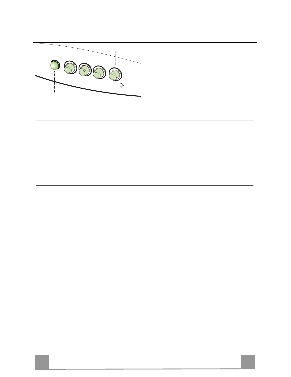
L
V1 V2 V3
S
0 - 1
MID MAX
0 - 1
L Luci Accende e spegne l’Impianto di Illuminazione.
S Led Led accensione Motore.
V1 Motore Accende e spegne il motore Aspirazione a velocità minima, adatta ad un
ricambio d’aria continuo particolarmente silenzioso, in presenza di pochi
vapori di cottura.
V2 Velocità Velocità media, adatta alla maggior parte delle condizioni d’uso, dato
l’ottimo rapporto tra portata d’aria trattata e livello sonoro.
V3 Velocità Velocità massima, adatta a fronteggiare le massime emissioni di vapore di
cottura, anche per tempi prolungati.
Page 10

IT
1
10
MANUTENZIONE
4 - MANUTENZIONE E PULIZIA
Una buona manutenzione garantisce un elevato rendimento, e una lunga durata della cappa.
ATTENZIONE: L'accumulo di grassi all'interno del filtro, oltre a pregiudicare il rendimento dell'apparecchio, può comportare anche rischi di incendio. Si raccomanda pertanto di attenersi scrupolosamente alle
istruzioni sotto indicate.
4.1 - Filtro antigrasso
È il filtro meccanico, fornito in diversi tipi alternativi, che trattiene le particelle di grasso. È posto all'interno della griglia di aspirazione.
Per la manutenzione operare come segue:
a-Generalità: Indipendentemente dal tipo del filtro, per toglierlo aprire la griglia e rimuovere gli appositi
fermi in filo metallico.
b-Filtro sottile a perdere (spessore circa 1 mm):
Non lavare, ma sostituire mediamente ogni 2 mesi. Se il filtro è dotato di indicatori chimici di saturazione
sostituire quando:
b.1-Il colore viola dei puntini visibili dall'esterno si è diffuso su tutta la superficie del filtro.
b.2-Il colore rosso delle strisce interne, normalmente non visibile, è diventato visibile dall'esterno.
c-Filtro metallico multistrato: va lavato mediamente 1 volta al mese in acqua con normale detersivo o in
lavastoviglie. Asciugare bene prima di rimontarlo.
4.2 - Pulizia Filtriantigrasso metallici Autoportanti
• Sono lavabili anche in lavastoviglie, e necessitano di essere lavati ogni 2 mesi circa di utilizzo o più
frequentemente, per un uso particolarmente intenso.
• Togliere i Filtri uno alla volta, spingendoli verso la parte posteriore del gruppo e tirando contemporaneamente verso il basso.
• Lavare i Filtri evitando di piegarli, e lasciarli asciugare prima di rimontarli.
• Rimontarli facendo attenzione a mantenere la maniglia verso la parte visibile esterna.
4.3 - Filtro al carbone attivo
È il filtro chimico che trattiene gli odori nella cappa filtrante. Per rimuoverlo, aprire la griglia e svitare il
pomello centrale metallico o ruotare leggermente in senso antiorario il filtro fino a sganciare la baionetta
centrale. Rimontare procedendo inversamente. Per un buon rendimento sostituire mediamente ogni 3
mesi.
4.4 - Illuminazione
Se una lampada non funziona o smette di funzionare, aprire la griglia di aspirazione e controllare che
sia ben avvitata. Se fosse necessario, cambiarla con un'altra di pari tipo o potenza.
4.5 - Pulizia
Pulire la cappa con acqua tiepida e detersivo liquido neutro; evitare l'uso di solventi, alcool e abrasivi.
Per tutte le operazioni dal punto 4.1 al punto 4.4 rispettare l'avvertenza 1.9, in particolare per l'operazione 4.3.
Page 11

EN
1
11
GENERAL INFORMATION - SAFETY WARNINGS
GENERAL INFORMATION
This canopy hood is designed to be fixed to any rigid vertical surface, over a gas or electric hotplate and
can be used either in the extraction mode (ducted to the outside) or in the recircu-lation mode (internal
recycling). All cookers hood perform better when used in evacuation mode. During winter time it may be
convenient to use the hood in the recycling mode to avoid heat loss from the kitchen.
Before starting the installation, consideration should be given to the difficulties to be found during installation. The installation work must be undertaken by a qualified and competent person
in conformity to the rules concerning the evacuation of contaminated air.
The manufacturer disclaims all liability for any damage or injury caused as a result of not following the instructions for installation contained in the following text.
1 - SAFETY WARNINGS
1.1 - When used in the extraction mode, the cooker hood ducting must not be connected to a flue
which is used for exhausting fumes from appliances supplied with energy other than electric,
such as a central heating flue or water heating flue.
1.2 - Before connecting to the mains supply ensure that the mains voltage corresponds with the voltage on the rating plate inside the hood.
1.3 - Connect the cooker hood to the mains via a bipolar switch which has 3mm clearance between
the contacts.
1.4 - For cooker hoods featuring an earth cable, make sure the electric plant of your house is correctly earthed.
1.5 - Appliance in class II are provided with a double insulation; therefore do not connect then
through earthed plugs but through simple bipolar plugs.
1.6 - When installed, the hood must be positioned at least 65cm above the hotplate.
1.7 - Never do flambé cooking under this cooker hood.
1.8 - Never leave frying pans unattended during use as overheated fat and oil may catch fire.
1.9 - Before carrying out any kind of maintenance or cleaning, disconnect the hood from the mains
supply.
1.10- If the room where the cooker hood is to be used contains a fuel burning appliance such as a central heating boiler then this must be of the room sealed or balanced flue type. If other types of
flue or appliance are fitted, ensure that there is an adequate supply of air into the room. When
the cooker hood is used in conjunction with appliances supplied with energy other than electric,
the negative pressure in the room must not exceed 0,04 mbar to prevent fumes being drawn
back into the room by the cooker hood.
1.11- The appliance must be positioned so that the plug is accessible.
1.12- If the supply cord is damaged, it must be replaced by a special cord or assembly available from
the manufacturer or its service agent.
Page 12

EN
1
12
INSTALLATION
2 - INSTALLATION INSTRUCTIONS
Some installation systems require the opening and removal of the metal grille panel.
2.1 - Instructions for opening and removing the metal grille panel
To open the grille panel, press inwardly on the two slider catches at each side of the grille
panel and the grille will pivot down.
To remove the metal grille, pull forward on the right hand side so that the hinge pin on the
back of the grille will be released from the slot in the side of the casing.
2.2 - Wall cabinet fixing
a - Predrilled wall cabinet: fix the hood onto the wall cabinet base panel using the four screws 4.2
x 45 mm (supplied with the fixing kit).
It is not necessary to open the metal grille.
b - No predrilled wall cabinet:
b.1 - If the hood is provided with a paper fixing template, follow the instructions.
b.2 - If the hood is not provided with a paper fixing template, position the hood on
the wall cabinet base panel and pilot drill the 3.5 x 16 mm screws (not supplied with the
fixing kit) from the inside onto the wood.
2.3 - Wall mounting
a - Drill two Ø 8 mm holes on the wall using the paper template, insert two rawl plugs and two
4.2 x 44,4 mm screws leaving 5 mm untightened. Open the metal grille panel, hook the hood
on and fully tighten the screws.
b - If the hood is not provided with a paper fixing template, drill two Ø 8 mm holes (see draw.),
insert the plugs and screws, proceeding as directed under paragraph a.
c - For wall mounting using wallbrackets (optional), follow the instructions of the fixing tem-
plate.
d - Pay attention to the safety regulation of point 1.6.
2.4 - Choice of operating mode
a - Evacuation mode
To check that the hood is set up for evacuation, open the grille panel and make sure that the
conversion lever or the change-over knob on the centrifugal unit is in the DUCTING position.
The charcoal filter is not required.
For ducting to the outside, the hood is supplied with a rear and top outlet. A flange spigot of
100 mm diameter (120 mm in certain models) is usually fitted on the top outlet and a blanking
plug on the rear outlet. If you choose to duct the hood from the rear of the casing, you should
invert the position of the flange and of the blanking plug. Pay attention to the safety regulation
1.1.
b - Internal recirculation mode
To check that the hood is set up for recycling, open the grille panel and make sure that the
conversion lever or the change-over knob on the centrifugal unit is in the RECYCLING position.
The charcoal filter is to be fitted. To fit the charcoal filter, support the filter with one hand and
turn the thumb screw through the centre of the charcoal filter. If the filter is of the interlocking
type, turn the filter clockwise. The hood can remain connected to the outside.
2.5 - Electrical connection and working test
1 - The safety measures 1.2, 1.3, 1.4 and 1.5 of paragraph 1 are to be strictly observed.
2 - Once the electrical connection has been completed, check that the worktop illumination,
motor and speeds work properly.
Page 13

EN
1
13
USE
L
V1 V2 V3
S
0 - 1
MID MAX
0 - 1
L Light Switches the lighting system on and off.
S Led Motor running led.
V1 Motor Switches the extractor motor on and off at low speed. Used to provide a
contin-uos and silent air change in the presence of light cooking vapours.
V2 Speed Medium speed, suitable for most operating conditions given the optimum
treated air flox/noise level ratio.
V3 Intensive Maximum speed, used for eliminating the highest cooking vapour emission,
including long periods.
Page 14

EN
1
14
MAINTENANCE
4 - MAINTENANCE AND CLEANING
Regular maintenance and cleaning will ensure good performance and reliability, while extending the
working-life of the hood. Special attention should be reserved to the grease filter and to the charcoal filter (recycling mode).
4.1 - Grease filter
This retains the solid grease particles and can be supplied in different types. lt is fitted onto the reverse
side of the metal grille panel. Maintenance of the grease filter varies according to the used type.
a-Whatever type of filters used, the filter is easily removed from the grille by pushing the metal wire clips
to one side and removing.
b-Thin synthetic filter (1 mm thick). It should not be washed and should be replaced every two months. If
the filter is provided with a saturation indicator, replace when:
b.1-The violet colour of the dots, which are visible through the metal grille, is spread over the whole
surface of the filter.
b.2-The red colour of the stripes, which is not visible through the metal grille when the filter is clean,
becomes visible from the outside of the metal grille.
c-Multi-layer metal filter. It should be washed once a month in hot water using mild detergent or liquid
soap. It can be washed in a dish-washer. It should not be bent and should be left to drain dry.
WARNING: An excess of grease in the filter not only would affect the performance of the hood, but it is
also a possible fire risk. We strongly recommend therefore to clean and replace filters in accordance
with the manufacturer instructions.
4.2 - Cleaning Metal self- supporting Grease Filters
• The filters are washable and must be cleaned at least every 2 months of operation, or more
frequently for particularly heavy usage.
• Remove the filters one at a time by pushing them towards the back of the group and pulling down at
the same time.
• Wash the filters, taking care not to bend them. Allow them to dry before refitting.
• When refitting the filters, make sure that the handle is visible on the outside.
4.3 - Charcoal filter
The charcoal filter is a chemical filter to be used only when the hood is in the recycling position. To replace the charcoal filter, open the grille and remove the thumb screw through the centre of the charcoal
filter. If the filter is of the interlocking type, turn the filter anticlockwise. Replace by reversing the operation. For a good performance replace the charcoal filter on average every three months.
4.4 - Worktop illumination
If a lamp fails to function at any time, open the metal grille panel and check that the lamp is fully
screwed into the holder. When changing the lamp, an identical replacement must be fitted to ensure a
safe working of the hood.
4.5 - Cleaning
The metal work should be cleaned regularly, at least once a month, using mild household cleaner and
polish. Never use abrasives. For all operations from point 4.1 to point 4.4 and in particular for point 4.3,
pay special attention to the safety regulation 1.9.
Page 15

FR
1
15
GENERALITES - CONSEILS CONCERNANT LA SECURITE
GENERALITES
Cette hotte est destinée à être installée au mur, au dessus d’un plan de cuisson.
Elle peut être utilisée en version évacuation (raccordement extérieur) ou recyclage (recyclage interne).
Les meilleures performances s'obtiennent dans la version en évacuation extérieure. De toute façon il est
conseillable d'utiliser la hotte dans la version recyclage pendant l'hiver pour éviter des dispertions de
chaleur.
A cause de la complexité de l’appareil il est préférable que l’installation soit effectuée par un
spécialiste tout en respectant les prescriptions des autorités concernant l’évacuation de l’air.
La responsabilité du producteur ne saurait être engagée pour tout incident ou accident provoqué par une installation défectueuse.
1 - CONSEILS CONCERNANT LA SECURITE
1.1 - N’utilisez jamais pour le raccordement une cheminée servant de conduit de fumée (chaudières,
cheminées, etc...)
1.2 - Vérifiez que la tension du secteur soit identique aux valeurs indiquées sur la plaquette signalétique figurant à l’intérieur de la hotte.
1.3 - Reliez la hotte au réseau en interposant un interrupteur bipolaire avec ouverture des contacts de
3 mm au moins.
1.4 - Pour les hottes avec cable de mise à la terre assurez-vous que l’installation électrique de votre
logement ait une mise à la terre correcte.
1.5 - Les hottes en classe II ont un double isolement; elles ne doivent donc pas être branchées avec
une fiche équiée de mise à la terre mais avec une simple fiche bipolaire.
1.6 - La distance de sûreté minimum entre le plan de cuisson et la hotte est de 65 cm.
1.7 - Il est interdit de faire flamber des préparations sous la hotte.
1.8 - Lorsque des fritures sont effectuées sous la hotte en fonctionnement, elles doivent faire l’objet
d’une surveillance permanente: l’huile surchauffée pourrait s’enflammer.
1.9 - Avant d’effectuer le nettoyage ou l’entretien de la hotte, débranchez l’appareil ou agissez sur
l’interrupteur omnipolaire de votre installation.
1.10- Une ventilation convenable de la pièce doit être prévue si une hotte de cuisine et des appareils
alimentés par une énergie autre que l’énergie électrique évacuent les fumées simultanément.
Une utilisation sans dangers est possible si la dépression maximum qui se crée dans la pièce
est inférieure à 0,04 mbar, ce que évite un retour des gaz de décharge dans la pièce.
1.11- L’appareil doit être placé de façon telle que la fiche de prise de courant soit accessible.
1.12- Si le câble d’alimentation est endommagé, il doit être remplace par un câble ou un ensemble
spécial disponible auprés du fabricant ou son service après vente.
Page 16

FR
1
16
INSTALLATION
2 - MONTAGE
Quelques systèmes d'installation prévoient l'ouverture et l'enlèvement de la grille d'aspiration.
2.1 - Ouverture et enlèvement de la grille d'aspiration
Pour ouvrir la grille déplacer vers le centre les boutons situés dans la partie inférieure de la hotte. Ouvrir
la visière. La grille glissera autour des pivots postérieurs. La grille ouverte et en position verticale, déplacer en avant le pivot postérieur droit le long de l'ouverture latérale jusqu'à sa sortie.
2.2 - Installation au dessous d'un meuble
a - Meuble préperçé: fixer la hotte au meuble à travers les trous prédisposés sur la base du meuble en utili-
sant les 4 vis 4,2 x 45 mm. Il n'est pas nécessaire d'ouvrir la grille.
b - Meuble non perçé:
b.1-Si avec la hotte il y a un gabarit de per-çage, il faut suivre ses instructions.
b.2-Si le gabarit n'est pas fourni, ouvrir la grille, appuyer la hotte contre la base du meuble et visser de
l'intérieur directement au bois en utilisant des vis 3,5 x 16 mm non fournies.
2.3 - Installation au mur
a - A l'aide de l'éventuel gabarit de perçage faire deux trous de Ø 8 mm dans le mur, appliquer les deux
chevilles, insérer deux vis 4,2 x 44,5 mm en laissant 5 mm non vissés. Déplacer la grille d'aspiration,
accrocher la hotte aux deux vis et procéder de l'intérieur au serrage définitif des vis.
b - Si le gabarit n'est pas disponible, faire deux trous Ø 8 mm, insérer chevilles et vis et procéder comme
au paragraphe a.
c - Pour une installation au mur avec des équerres (en option) s'en tenir aux instructions reportées sur le
gabarit annexé.
d - Respecter le conseil 1.6.
2.4 - Choix de la version
a - Evacuation
Ouvrir la grille d'aspiration et positionner le levier de conversion ou l'aiguille du bouton sur la position
"aspirante" à la fin de son parcours. Enlever, si fourni, le filtre à charbon, en dévissant le pommeau central ou en tournant lente-ment dans le sens contraire à celui des aiguilles d'une montre pour décrocher
l'attaque centrale à baïonette.
Relier le tuyau extérieur à un anneau de raccord Ø 100 mm (ou Ø 120 mm pour quelques modèles) situé au dessous ou à l'arrière selon les nécessités. Obstruer la sortie non utilisée avec le cache prévu à
cet effet. Respecter le conseil 1.1.
b - Recyclage
Ouvrir la grille d'aspiration et positionner le levier de conversion ou l'aiguille du bouton sur la position "filtrante" à la fin de son parcours.
Appliquer le filtre à charbon actif au support du moteur à l'aide du pommeau central en tournant lentement dans le sens des aiguilles d'une montre pour accrocher l'attaque centrale à baïonette. La hotte
peut eventuellement rester branchée à un conduit.
2.5 - Raccordement électrique et contrôle fonctionnel
1 - Il est nécessaire de respecter scrupuleusement les conseils 1.2, 1.3, 1.4 et 1.5 du paragraphe 1
concernant la sécurité.
2 - Le raccordement électrique effectué, vérifiez le bon fonctionnement de l’éclairage, du moteur et du
changement des vitesses d’aspiration.
Page 17

FR
1
17
UTILISATION
L
V1 V2 V3
S
0 - 1
MID MAX
0 - 1
L Lumières Allume et éteint l’installation de l’éclairage.
S Del Del allumage Moteur.
V1 Moteur Met en marche et à l’arrêt le moteur aspiration à vitesse minimale, pour un
rechange d’air permantent particulièrement silencieux en cas de faibles vapeurs de cuisson.
V2 Vitesse Vitesse moyenne pour la plupart des conditions d’utilisation, étant donné le
rapport optimal entre débit d’air traité et niveau sonore.
V3 Vitesse Vitesse maximum, pour faire face aux émissions maximum de vapeur de
cuisson, même pendant des temps prolongés.
Page 18

FR
1
18
ENTRETIEN
4 - ENTRETIEN ET NETTOYAGE
Un bon entretien est la garantie d'un bon fonctionnement et d'un bon rendement de la hotte.
ATTENTION: L'accumulation de graisse à l'intérieur du filtre peut nuire au rendement de l'appareil et
provoquer des risques de feu. On conseille pourtant de respecter les instructions ci-dessous.
4.1 - Filtre à graisse
Il s'agit d'un filtre mécanique, fourni en dif-férents types alternatifs, qui retient les particules de graisse. Il
est situé à l'intérieur de la grille d'aspiration. Pour l'entretien agir comme suit:
a-Généralités
Pour enlever n'importe quel type de filtre, ouvrir la grille et déplacer les arrêts métalliques.
b-Filtre mince à perdre (épaisseur 1 mm environ). Ce filtre ne peut être lavé; il doit être remplacé tous
les deux mois.
Si le filtre est fourni d'indicateurs chimiques de saturation, il faut le substituer si:
b.1 -La couleur violet des pois visibles à l'ex-térieur aura couvert toute la surface du filtre.
b.2 -La couleur rouge des bandes à l'intérieur, normalement pas visibles, sera visible à l'extérieur.
c-Filtre métallique multi-couche
Il doit être lavé tous les mois à l'eau tiède avec un détergent normal. Vous pouvez également le laver
dans votre lave-vaisselle. Laisser-le sécher avant de le replacer.
4.2 - Nettoyage Filtresantgi - Graisse Metallique S autoporteurs
• Ils peuvent être lavés au lave-vaisselle et nécessitent d’être nettoyés environ tous les 2 mois
d’emploi ou plus fréquemment en cas d’emploi particulièrement intense.
• Retirer les filtres l’un aprés l’autre, en les poussant vers la partie arrière du groupe et en tirant si-
multanément vers le bas.
• Laver les filtres en évitant de les plier et les laisser sécher avant de les remonter.
• Remonter les filtres en veillant à ce que la poignée reste vers la partie visible externe.
4.3 - Filtre à charbon actif
Il s'agit d'un filtre chimique qui retient les odeurs dans la hotte à recyclage. Pour l'enlever, ouvrir la grille
et dévisser le pommeau central en métal. Tourner légèrement le filtre dans le sens contraire à celui des
aiguilles d'une montre jusqu'à décrocher la baïonette centrale. Pour le replacer procéder en séquence
inverse. Afin d'obtenir le meilleur rendement, ce filtre doit être remplacé tous les trois mois.
4.4 - Eclairage
Si une lampe ne fonctionne pas, ouvrir la grille d'aspiration et contrôler qu'elle soit bien vissée. S'il est
nécessaire, substituer-la par une autre du même type et de la même puissance.
4.5 - Nettoyage
Nettoyer la hotte à l'eau tiède et avec du détergent liquide neutre. N'employez jamais de produits abrasifs ou caustiques.
Pour toutes les opérations du point 4.1 au point 4.4 respecter scrupuleusement le conseil 1.9, particulièrement pour l'opération 4.3.
Page 19

DE
1
19
ALLGEMEINES - SICHERHEITSHINWEISE
ALLGEMEINES
Diese Dunstabzugshaube ist zur Wandmontage über einem Kochfeld vorgesehen. Die Haube kann als Umluftoder Abluft-Haube verwendet werden. Die besten Leistungen erhält man in Abluftversion; jeden Falls kann die
Haube im Winter in Umluftversion betrieben werden: man spart auf diese Weise Hitzerverlust.
Wegen des beträchtlichen Eigengewichtes der Haube empfiehlt es sich, die Anbringung von geschultem
Personal durchführen zu lassen, wobei alle behördlichen Bestimmungen über Luftableitung zu beachten
sind. Für Schäden, die durch nicht vorschriftsmäßige oder unsachgemäße Anbringung verursacht werden, lehnt der Hersteller jegliche Haftung ab.
SICHERHEITSHINWEISE
1 - Die Dunstesse nicht an Rauch- oder Abgaskamine anschließen, die noch für offene Feuerstellen benutzt werden.
Bei der Ableitung von Abluft sind die behördlichen Bestimmungen zu beachten. Gegebenenfalls ist der zuständige
Schornsteinfeger-Meister zu befragen.
2 - Es ist sicherzustellen, daß die Netzspannung den Anschlußwerten auf dem Typenschild im Inneren der Dunstesse
entspricht.
3 - Es muß gewährleistet sein, daß nach erfolgter Montage des Gerätes der Schutzkontaktstecker erreichbar ist; an-
dernfalls ist bei direktem Anschluß der Dunstesse ein zweipoliger Schalter, mit einem Öffnungsweg von mindestens 3 mm für jeden Pol, zwischenzuschalten.
4 - Bei Hauben mit Schutzleiter ist es sicherzustellen, daß die Wohnung über eine vorschriftsmäßige Erdung verfügt.
5 - Dunstabzugshauben in Schutzklasse II haben eine Doppelt-Isolierung; deswegen sind sie nicht mit einem Erdste-
cker sondern mit einem normalen zweipoligen Stecker anzuschließen.
6 - Der Sicherheitsabstand zwischen Kochstelle und Dunstesse soll mindestens 65 cm betragen.
7 - Das Flambieren unter der Dunstesse ist zu unterlassen. Achtung Brandgefahr!
8 - Frittiergeräte, die unter der Dunstesse betrieben werden, sind während der gesamten Betriebsdauer zu beaufsich-
tigen. Achtung Brandgefahr!
9 - Die Filter dieser Dunstabzugshaube müssen in regelmäßigen Zeitabständen gereinigt oder erneuert werden. Fett-
getränkte Filter sind leicht brennbar: daher ist der in dieser Anleitung unter der Rubrik “Wartung” angegebene Reinigungsrhythmus unbedingt einzuhalten. Vor jedem Reinigungsvorgang, vor dem Filterwechsel und vor Instandsetzungsarbeiten ist entweder der Gerätestecker aus der Steckdose zu ziehen, der Hauptschalter (allpolig) abzuschalten oder die Sicherung herauszudrehen.
10 - Wenn in dem Raum außer der Haube andere, nicht elektrisch betriebene Geräte (z.B. Gas, Ölöfen) betrieben
werden, muß für ausreichende Lüftung (Zuluft) gesorgt werden. Bitte in diesem Zusammenhang den folgenden
Absatz besonders beachten. Wichtiger Hinweis für den Abluftbetrieb Bei gleichzeitigem Betrieb einer Dunstabzugshaube und einer raumluftabhängigen Feuerstätte (wie z.B. gas-, öl oder kohlebetriebene Heizgeräte, Durchlaufer-hitzer, Warmwasserbereiter) ist Vorsicht geboten, da beim Absaugen der Luft durch die Dunstabzugshaube
dem Aufstellraum die Luft entnommen wird, die die Feuerstätte zur Verbrennung benötigt. Ein gefahrloser Betrieb
ist möglich, wenn bei gleich-zeitigem Betrieb von Haube und raumluftabhängiger Feuerstätte im Aufstellraum der
Feuerstätte ein Unterdruck von höchstens 0,04 mbar erreicht wird und damit ein Rücksaugen der Feuerstättenabgase vermieden wird. Dies kann erreicht werden, wenn durch nicht ver-schließbare Öffnungen, z.B. Türen, Fenster, Zuluft/Abluftmauerkästen oder andere technische Maßnah-men, wie gegenseitige Verriegelung o.ä., die
Verbren-nungsluft nachströmen kann.
Anmerkung: Bei der Beurteilung muß immer der gesamte Lüftungsverbund der Wohnung beachtet werden.
Bei Betrieb von Kochgeräten, z.B. Koch-mulde und Gasherd, wird diese Regel nicht angewen-det.
Im Zweifelsfalle muß der zuständige Schornsteinfe-germeister zu Rate gezogen werden. Wenn die Dunstabzugshaube im
Umluftbetrieb - unter Verwendung eines separat zu beschaffenden Aktiv-kohlefilters - verwendet wird, ist der Betrieb ohne
Einschränkung möglich.
Abluft:
Der Abluftkanal darf nur an einen Luftschacht an-geschlossen werden (nicht an einen noch benutzten Kamin!) oder sollte
direkt ins Freie führen. Der Weg des Abluftkanals von der Dunstabzugshaube bis zum Luftschacht sollte nicht mehr als 45 Meter betragen und möglichst gerade verlegt werden. Ist der Weg länger oder mit mehreren Bogen versehen, kann eine
erhebliche Verschlechterung der Luft-leistung die Folge sein. Bei Reduzierung des Abluft Querschnitts, z.B. durch Kleinere Flachkanalsysteme, tritt gleichfalls eine erhebliche Verschlechterung der Luftleistung sowie ein Anstieg der Geräuschbildung ein. Es wird daher in solchen Fällen die Installation von Umluftgeräten empfohlen.
Page 20

DE
2
20
MONTAGE
2 - MONTAGE
a - Wandmontage
Unter Verwendung der jeder Haube beiliegenden Bohrschablone werden zwei 8 mm Dübel ein-gesetzt
und die Schrauben 4,2 x 44,4 mm einge-dreht (Abstand von Schraubenkopf zur Wand ca. 5 mm).
Das Fettfiltergitter der Dunstabzugshaube (nach Betätigen der seitlichen Kunststoffschieber zur Gerätemitte hin) abklappen und herausnehmen. Die Dunstabzugshaube unter Benutzung der an der Rückwand angeordneten "Schlüssellöcher" an den Wandschrauben einhängen und diese sodann festdrehen.
Einige Geräteversionen sind mit zusätzlichen Wandbefestigungslaschen ausgestattet (Mehr-preis). Diese Laschen können unter Verwendung von Dübeln und Schrauben an der Wand be-festigt werden, und
die Dunstabzugshaube kann eingehangen werden.
Der beiliegende Arretierungswinkel wird nach dem Einhängen der Haube hinten oben, im Winkel am
Gerät und an der Wand anliegend angeschraubt. Dadurch wird unbeabsichtigtes "Ausheben" der
Dunstabzugshaube vermieden.
b - Schrankmontage
In der Haubenoberseite sind mehrere Bohrungen eingearbeitet, die eine Befestigung unter Hängeschränken ermöglichen. Nach dem Anbringen der entsprechenden Bohrungen an der Schrankunterseite (Bohrschablone verwenden), kann die Haube unter Verwendung der beiliegenden Schrauben
mit dem Schrank verschraubt werden.
Während der Montage muß die Dunstabzugs-haube nach unten abgestützt werden.
c - Montage Abluftführung
Bei Ablufthauben muß zusätzlich ein Abluftrohr vom Luftaustritt am Gerät nach außen verlegt werden
(Material im Handel erhältlich). Die Dunstabzugshaube ist mit einem Luftabgang nach hinten und nach
oben versehen. Durch Austauschen der Verschlußscheibe und des Luftstutzens kann beliebig die gewünschte Geräteöffnung für den Luftabgang gewählt werden. Scheibe und Stutzen können durch eine
Drehbewegung aus den Gehäuseausschnitten genommen und umgekehrt wieder eingesetzt werden.
Sofern das obere Gehäuseloch als Luftabgang benutzt wird, muß im Boden des Hängeschran-kes analog ein runder Ausschnitt in den Schrank-boden gesägt werden, wiederum unter Benut-zung der Bohrschablone.
d - Montage bei Umluft
Bei Hängeschränken von mehr als 35 cm Tiefe muß darauf geachtet werden, daß die Haube so weit
nach vorn angeschraubt wird, daß die vorderen Luftschlitze in der Haubenoberseite frei vor der
Schranktüre liegen, damit die Umluft ungehindert in den Raum zurückströmen kann.
Bei Umlufthauben müssen die beim Kunden-dienst oder im Zubehörhandel erhältlichen Aktivkohlefilter
innerhalb des Gerätes einge-setzt werden.
Elektrischer Anschluß und Funktionskontrolle
a - Für den Anschluß an das 220-Volt-Wechselstromnetz ist die Dunstabzugshaube mit einem festmontier-
ten Kabel und einem Schutzkontaktstecker versehen.
Der Gesamtanschlußwert (Motor und Beleuchtung) ist dem Typenschild zu entnehmen.
Die in der Montageanleitung besonders hervorgehobenen Sicherheitshinweise, insbesondere die Punkte 2, 3, 4 und 5 von Abschnitt sind strengstens zu beachten.
b - Nach Durchführung des elektrischen Anschlusses wird die Funktionskontrolle bezüglich Beleuchtung,
Einschalten des Motors und Wechseln der Schaltstufen durchgeführt.
Page 21

DE
2
21
BEDIENUNG
L
V1 V2 V3
S
0 - 1
MID MAX
0 - 1
L Beleucht. Schaltet die Beleuchtung ein und aus.
S Led Betriebsanzeigelampe.
V1 Motor Schaltet den Gebläsemotor mit minimaler Geschwindigkeit ein oder aus.
Diese Stufe ist für einen ständigen und besonders leisen Luftaustausch bei
geringer Kochdunstentwicklung geeignet.
V2 Geschw. Mittlere Gebläsestufe, eignet sich aufgrund des guten Verhältnisses zwi-
schen Fördervolumen und Geräuschentwicklung für die meisten Anwendungssituationen.
V3 Geschw. Höchste Gebläsestufe, eignet sich für starke Kochdunstentwicklung, auch
über längere Zeit hin.
Page 22

DE
2
22
WARTUNG
4 - WARTUNG UND PFLEGE
Eine regelmäßige Wartung garantiert einen einwandfreien Betrieb und gute Leistungen über lange Zeit
hin.
ACHTUNG: Ansammlungen von Fett im Inneren des Filters können die Leistung des Gerätes beeinträchtigen und Brandgefahr verursachen. Deshalb weisen wir darauf hin, dass nachstehende Anleitungen genauestens einzuhalten sind.
4.1 - Fettfilter
Dies ist ein mechanischer Filter in verschiedenen Arten, der die Fettpartikel auffängt.
Er befindet sich im Inneren des Sauggitters.
Bei der Wartung folgendermaßen vorgehen:
a-Allgemeines: unabhängig vom Filtertyp ist das Sauggitter zu öffnen, um die Entnahme zu ermöglichen; die Haltedrähte aus Metall entfernen.
b-Dünner Einwegfilter (ca. 1 mm dick):
Er kann nicht gereinigt werden, sondern muss durchschnittlich alle zwei Monate ausgetauscht werden.
Verfügt der Filter über eine chemische Sättigungsanzeige, wird er ausgetauscht, wenn:
b.1 - die von außen sichtbaren roten Punkte auf der gesamten Oberfläche verteilt sind.
b.2 - die rote Farbe der internen Streifen von außen sichtbar geworden ist (normalerweise nicht
sichtbar).
c-Mehrschicht-Metallfilter: diese Filter durchschnittlich einmal pro Monat mit normalem Haushaltsreiniger
und Wasser oder im Geschirrspüler waschen. Gut trocknen lassen, bevor sie wieder montiert werden.
4.2 - Selbsttragende Metallfettfilte
• Diese Filter können auch im Geschirrspüler gewaschen werden und sind alle 2 Betriebmonate bzw.
bei intensivem Einsatz auch häufiger zu reinigen.
• Jeden Filter einzeln entnehmen, indem sie zur Rückseite der Haube geschoben und gleichzeitig nach
unten gezogen werden.
• Darauf achten, dass die Filter beim Waschen nicht verbogen werden und diese vor dem Wiederein-
setzen vollkommen trocknen lassen.
• Bei der Remontage darauf achten, dass sich der Griff auf der sichtbaren Seite befindet.
4.3 - Aktivkohlefilter
Dies ist ein chemischer Filter, der die Gerüche bei Umlufthauben auffängt. Für die Demontage das
Sauggitter öffnen, den zentralen Kugelgriff aus Metall losschrauben oder den Filter etwas gegen den
Uhrzeigersinn drehen, bis der zentrale Bajonettverschluss ausgehakt wird. Bei der Remontage in umgekehrter Reihenfolge vorgehen. Um gute Leistungen zu erzielen, soll der Filter durchschnittlich alle 3 Monate ausgetauscht werden.
4.4 - Beleuchtung
Falls eine Lampe nicht oder nicht mehr funktioniert, das Sauggitter öffnen und kontrollieren, dass die
Lampe fest eingeschraubt ist. Im Bedarfsfall durch eine Lampe gleichen Typs oder gleicher Leistung ersetzen.
4.5 - Reinigung
Die Haube mit lauwarmem Wasser und neutralem Flüssigreiniger säubern; keinesfalls Lösemittel, Alkohol und Schmirgelprodukte verwenden. Bei allen Arbeitsschritten ab Punkt 4.1 bis
Punkt 4.4 den Sicherheitshinweis 1.9 beachten, insbesondere beim Arbeitsschritt 4.3.
Page 23

TR
2
23
GENEL BĐLGĐLER - GÜVENLĐK UYARILARI
GENEL BĐLGĐLER
Bu davlumbaz, bir pişirme tezgâhı üzerine gelecek şekilde, duvara yaslanması ve monte edilmesi tasarlanarak hazırlanmıştır.
Aspiratörlü (hava tahliyesi dışarı) ve filtreli (hava dolaşımı mekân içinde) versiyonlarda kullanılabilir. En iyi randıman aspiratörlü modelde elde edilir ; her hal-ü kârda, kış döneminde ısı
kaybını önlemek amacıyla davlumbazın filtreli versiyonunu kullanmak daha uygun olabilir.
Montajının uzman personel tarafından ve yerel mercilerin hava tahliye sistemleri ile ilgili yönetmelikleri gözetilmek suretiyle yaptırılması gerektiğini hatırlatırız.
Kuralına uygun şekilde yapılmayan hatalı montajlar neticesinde ortaya çıkabilecek zarar ve ziyan karşısında malın üreticisi her türlü sorumluluktan muaf olacaktır.
1 - GÜVENLĐK UYARILARI
1.1 - Grubu kazan, şömine vb. türde ısı üreten sistemlerin dumanlarının tahliye edildiği kanala bağlamayınız.
1.2 - Şebeke cereyanının grubun iç kısmındaki etikette belirtilen değerlere uygun olmasını
kontrol ediniz.
1.3 - Grubu şebekeye bağlarken bu ikisi arasına temas aralığı en az 3 mm olan çift kutuplu
bir elektrik anahtarı koyunuz.
1.4 - Toprak hattı olan davlumbazlarda evin elektrik tesisatının bunun doğru çalışmasını
sağlamaya yeterli olduğundan emin olunuz.
1.5 - Sınıf II'ye dahil davlumbazlarda çift yalıtım mevcuttur; topraklı prizle değil, basit çift
kutuplu prizle bağlantılı olarak çalışırlar.
1.6 - Pişirme tezgahı ile grup arasındaki mesafe en az 65 cm olmalıdır.
1.7 - Grubun altındaki tezgâhta alevde pişirme işlemleri yapmayınız.
1.8 - Fritözleri kullanırken dikkatli olunuz: aşırı kızan yağ alev alabilir.
1.9 - Her türlü bakım ve temizlik işlemine başlamadan önce, ya ana şalter ile, yada fişi prizden çekerek cihazın elektrik bağlantısını kesiniz.
1.10- Aynı mekânda hem bu grubun, hem de elektrikle çalışmayan (örneğin gazlı) cihazların
bir arada çalıştırılması halinde, ortamın gayet iyi havalandırılmış olması gerekir. Uygun
ve risksiz bir kullanım mekândaki ters basıncın (vakumun) en fazla 0,04 mBar olması ile
mümkündür; bu şekilde egzoz gazlarının geri dönüşü önlenir.
1.11- Cihaz, fişine her istenildiğinde erişilebilecek şekilde yerleştirilmelidir.
1.12- Besleme kablosu hasar görmüş ise imalâtçı firmadan veya yetkili servisten tedarik edilecek bir yenisi ile değiştirilmelidir.
Page 24

TR
2
24
MONTAJ
2 - MONTAJ
Bazı montaj sistemleri aspiratör ızgarasının açılmasını ve çıkarılmasını öngörmektedir.
2.1 - Aspiratör ızgarasının açılması ve çıkarılması
Izgarayı açmak için davlumbazın alt kısmında bulunan düğmeleri ortaya (merkeze) doğru sürünüz. Görme bölmesini açınız. Izgara iki adet arka pim üzerinde dönerek inecektir.
Izgara açık ve dikey konumdayken, sağ arka pimi yan kanal boyunca dışarı çıkana kadar ittiriniz.
2.2 - Mobilya-raf altına montaj
a - Delinmiş mobilya: davlumbazı mobilyaya bunun kaidesinde açılmış deliklerden sabitleyiniz
ve bu iş için ürünle birlikte verilmiş olan 4,2 x 44,4 ebatlı 4 adet vidayı kullanınız. Izgarayı
açmaya gerek yoktur.
b - Delinmemiş mobilya:
b.1- Eğer davlumbaz beraberinde bir delik delme şablonu verilmişse bunun üzerinde yer alan
talimatları yerine getiriniz.
b.2- Eğer böyle bir şablon yoksa, ızgarayı açınız, davlumbazı mobilyanın tabanına yaslayınız
ve ürün beraberinde verilen 3,5 x 16 ebadındaki vidalarla içerden ahşaba vidalayarak sabitleyiniz.
2.3 - Duvara montaj
a - Varsa delik delme şablonunu kullanarak duvara 8 mm çapında 2 delik açınız, iki adet dübel
koyunuz, 4,2 x 44,4 ebatlı iki vidayı yerleştirip 5 mm.lik kısmı dışarıda kalacak şekilde
bırakınız, aspiratör ızgarasını çıkarınız, davlumbazı arkasındaki deliklerden yarı çıkık
bırakılan vidalara geçiriniz ve iç kısımdan bu vidaları sıkınız.
b - Eğer delik şablonu yoksa, 8 mm çapında 2 delik deliniz (bkz. resim) ve dübellerle vidaları so-
kup "a" paragrafındaki gibi devam ediniz.
c - Duvara braketlerle (opsiyonel) monte edilecek ise, bu parçalarla birlikte verilen şablonda yer
alan talimatları izleyiniz.
d - 1.6. maddedeki uyarıları dikkate alınız.
2.4 - Model seçimi
a - Aspiratörlü
Aspiratör ızgarasını açınız ve kolu yada düğme üzerindeki oku son nokta olan "aspiratör" pozisyonuna getiriniz. Varsa, orta topuzu gevşeterek yada geçmeli orta bağlantıyı kurtarmak için
sola doğru hafifçe döndürerek aktif karbon filtresinin kartuşunu çıkarınız.
Dış boruyu ihtiyaca göre üst yada arka çıkıştaki 100 mm.lik flanşa bağlayınız (bazı modeller
120 mm çapındadır). Boşta kalan deliğe tapayı takınız. 1.1. sayılı maddedeki uyarılara kesinlikle riayet ediniz.
b - Filtreli
Aspiratör ızgarasını açınız ve kolu yada düğme üzerindeki oku son nokta olan "filtre" pozisyonuna getiriniz.
Aktif karbon filtresini, orta metal topuz vasıtasıyla, yada geçmeli tipteki bağlantısını yapmak
için sağa doğru hafifçe döndürerek takınız. Varsa dış boru bağlı kalabilir.
2.5 - Elektrik bağlantısı ve işlevsel kontrol
1 - 1.ci paragraftaki güvenlikle ilgili 1.2, 1.3, 1.4 ve 1.5 sayılı maddelere titizlikle uymak gere-
kmektedir.
2 - Elektrik bağlantısı yapıldıktan sonra aydınlatma sisteminin, motorun ve farklı hızların doğru
çalışıp çalışmadıklarını kontrol ediniz.
Page 25

TR
2
25
KULLANIM
L
V1 V2 V3
S
0 - 1
MID MAX
0 - 1
L Lambalar Aydınlatma sistemini yakar ve söndürür
S Led Motorun çalışmakta olduğunu bildiren led lambası
V1 Motor Aspiaratör motorunu minimum hızda açar ve kapatır ; minimum hız sessi-
zce çalışarak aşırı pişirme buharı olmadığında sürekli hava dolaşımı sağlar.
V2 Hız Orta hız, kullanımın büyük kısmında yararlanılan hızdır, ses düzeyi ile hava
dolaşımı arasındaki oran optimumdur.
V3 Velocità Yüksek (maksimum) hız, uzun süreli olan ve çok fazla buhar açığa çıkaran
pişirme işlemlerinde kullanılmak içindir.
Page 26

TR
2
26
BAKIM
4 - BAKIMI VE TEMĐZLENMESĐ
Đyi bir bakım işlemi yüksek oranda randıman sağlar ve davlumbazın ömrünü uzatır.
DĐKKAT: Filtre içinde yağ birikmesi cihazın randımanını düşürmekten başka, yangın riskine
de davetiye çıkarır. Bu nedenle aşağıda verilen talimatlara titizlikle uyunuz.
4.1 - Yağ tutucu filtre
Farklı tiplerde sunulan mekanik bir filtredir, yağ zerreciklerini tutar. Aspiratör ızgarasının içine yerleştirilmiştir.
Bakımı için şu şekilde hareket ediniz:
a-Genelde: Filtrenin tipinden bağımsız olarak, çıkarmak için ızgarayı açınız ve metal tutucu
klipsleri sökünüz.
b-Kullanıldıktan sonra atılan ince filtre (yaklaşık kalınlığı 1 mm):
Yıkamayınız, ortalama 2 ayda bir değiştiriniz. Eğer filtrede kimyasal doyum göstergeleri
mevcut ise:
b.1- Dıştan görülen noktaların mor rengi filtrenin tüm yüzeyine yayıldığında, veya
b.2- Đçteki şeritlerin normalde görünmeyen kırmızı rengi dıştan bakınca görülür hale gel-
diğinde filtreyi değiştiriniz.
c-Çok katmanlı metal filtre: Ayda ortalama bir kez deterjanlı suda veya bulaşık makinesinde
yıkanır. Yerine takmadan önce iyice kurulayınız.
4.2 - Geçme sistemli metal yağ filtrelerinin temizlenmesi
• Bunlar bulaşık makinesinde de yıkanabilir ve kullanıma göre ortalama 2 ayda bir yada
daha sıkça yıkanmaları gerekir.
• Filtreleri tek tek ve önce arka kısma doğru ittirerek, aynı anda da aşağı doğru çekerek çıkarınız.
• Bunları katlayıp kıvırmadan yıkayınız ve yerine takmadan önce kurumalarını bekleyiniz.
• Yerlerine takarken kulpun dıştan görünür şekilde konumlandırılmasına dikkat ediniz.
4.3 - Aktif karbon filtresi
Filtre versiyonlu davlumbazda kokuları tutan kimyasal filtredir. Çıkarmak için ızgarayı açıp,
orta topuzu gevşetiniz yada filtreyi geçme sisteminden kurtarana kadar hafifçe sola doğru
döndürünüz. Ters yönde hareket ederek tekrar takabilirsiniz. Đyi randıman alabilmek için ortalama 3 ayda bir değiştiriniz.
4.4 - Aydınlatma sistemi
Eğer bir lamba çalışmıyorsa ızgarayı açıp ampulü kontrol ediniz. Gerekirse aynı tipte ve voltajda bir yenisi ile değiştiriniz.
4.5 - Temizlenmesi
Davlumbazı ılık su ve nötr sıvı deterjanla temizleyiniz. Solvent, alkol ve yıpratıcı maddeler
kullanmayınız. 4.1 ile 4.4 sayılı maddeler arasındaki işlemleri yaparken, bilhassa 4.3 sayılı
maddedeki işlem sırasında 1.9. sayılı paragrafta yapılan uyarıya titizlikle uyunuz.
Page 27

Page 28

436002787_ver3
Il simbolo sul prodotto o sulla confezione indica che il prodotto non deve essere considerato come un normale rifiuto domestico,
ma deve essere portato nel punto di raccolta appropriato per il riciclaggio di apparecchiature elettriche ed elettroniche. Provvedendo a
smaltire questo prodotto in modo appropriato, si contribuisce a evitare potenziali conseguenze negative per l’ambiente e per la salute,
che potrebbero derivare da uno smaltimento inadeguato del prodotto. Per informazioni più dettagliate sul riciclaggio di questo prodotto,
contattare l’ufficio comunale, il servizio locale di smaltimento rifiuti o il negozio in cui è stato acquistato il prodotto.
The symbol on the product or on its packaging indicates that this product may not be treated as household waste. Instead it shall
be handed over to the applicable collection point for the recycling of electrical and electronic equipment. By ensuring this product is
disposed of correctly, you will help prevent potential negative consequences for the environment and human health, which could otherwise be caused by inappropriate waste handling of this product. For more detailed information about recycling of this product, please
contact your local city office, your household waste disposal service or the shop where you purchased the product.
Le symbole sur le produit ou son emballage indique que ce produit ne peut être traité comme déchet ménager. Il doit plutôt être
remis au point de ramassage concerné, se chargeant du recyclage du matériel électrique et électronique. En vous assurant que ce
produit est éliminé correctement, vous favorisez la prévention des conséquences négatives pour l’environnement et la santé humaine
qui, sinon, seraient le résultat d’un traitement inapproprié des déchets de ce produit. Pour obtenir plus de détails sur le recyclage de ce
produit, veuillez prendre contact avec le bureau municipal de votre région, votre service d’élimination des déchets ménagers ou le
magasin où vous avez acheté le produit.
Das Symbol auf dem Produkt oder seiner Verpackung weist darauf hin, dass dieses Produkt nicht als normaler Haushaltsabfall
zu behandeln ist, sondern an einem Sammelpunkt für das Recycling von elektrischen und elektronischen Geräten abgegeben werden
muss. Durch Ihren Beitrag zum korrekten Entsorgen dieses Produkts schützen Sie die Umwelt und die Gesundheit Ihrer Mitmenschen.
Umwelt und Gesundheit werden durch falsches Entsorgen gefährdet. Weitere Informationen über das Recycling dieses Produkts
erhalten Sie von Ihrem Rathaus, Ihrer Müllabfuhr oder dem Geschäft, in dem Sie das Produkt gekauft haben.
Ürün veya paketi üzerindeki sembolü, bu ürünün normal bir evsel atık olarak görülmemesi ve bu tip elektrikli veya elektronik
cihazların atıldığı dönüşümlü toplama noktalarına terkedilmesi gerektiğine işaret eder. Bu ürünü gerektiği gibi elimine etme kurallarına
uyarsanız çevre ve insan sağlığı üzerindeki olumsuz etkilerini bertaraf etmeye katkı sağlamış olursunuz. Bu ürünün geri dönüşüm
koşulları hakkında daha ayrıntılı bilgi için hudutları içinde bulunduğunuz belediyenin ilgili diaresine, atık yoketme servisine veya ürünün
satıcısına danışınız.
Franke S.p.a.
Via Pignolini,2
37019 Peschiera del Garda (VR)
www.franke.it
73/23/CEE
Dir. 89/336/CEE
93/68/CEE
 Loading...