

Page 1
New Product Introduction
Transit 2006.5 (04/2006-)
Service Information
Technical Service Training
CG 8171/S en 12/2005
TN7002156H
Page 2

T o the best of our kno wledge, the illustrations, technical information, data and descriptions in this issue were correct at the time
of going to print. The right to change prices, specifications, equipment and maintenance instructions at any time without notice
is reserved as part of FORD policy of continuous development and improvement for the benefit of our customers.
No part of this publication may be reproduced, stored in a data processing system or transmitted in any form, electronic,
mechanical, photocopy , recording, translation or by any other means without prior permission of Ford-Werke GmbH. No liability
can be accepted for any inaccuracies in this publication, although every possible care has been taken to mak e it as complete and
accurate as possible.
Copyright ©2006
Ford-Werke GmbH
Service training programs D-F/GT1 (GB)
Page 3

Preface
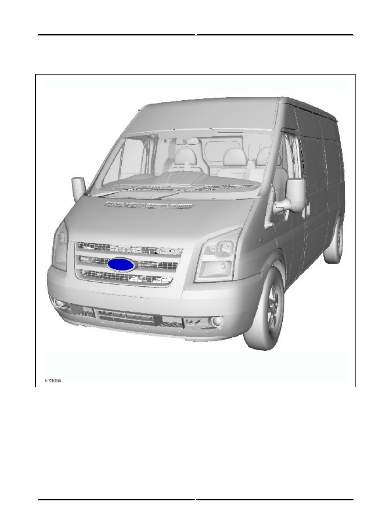
Model year 2006.5 will see the introduction of a modified front end as well as a range of new functions and equipment
options for the Transit. Also available will be two new body versions; one with a higher payload as well as a van
with medium wheelbase and flat roof (front wheel drive).
As well as the modification of the outer appearance, the interior of the driver cab has also been completely redesigned.
In addition to a multitude of storage compartments, the new interior offers the latest generation of audio units, a
navigation system, a hands-free kit, a Bluetooth interface and voice control for the phone and audio functions ex
works.
The 1,850 kg front axle load version has been added to the range. Disc brakes are installed on the rear axle.
Furthermore, stability assist is available as an option.
The previous 2.0L Duratorq TDCi engines ha ve been replaced by a modified generation upgraded to a cubic capacity
of 2.2 liters. The 2.4L Duratorq TDCi engine versions have also been modified, while consumption has been
reduced. All engines meet emission standard IV.
The vehicle electrical system has undergone significant modif ication; in addition to providing an instrument cluster
with message center it now also permits some custom setting options for the locking system. A second battery
(standard on all rear wheel drive versions) as well as a function for charging the radio remote control represent a
marked improvement in terms of the power supply.
Protection against theft and ease of repair with regard to the control modules have been notably improved by an
innovative Controller Area Network.
The body has again been modified with regard to its crash characteristics. In addition, side air bags and ISOfix
mounting points are now available on the Transit for the first time.
You should get to know the new systems, their operation and their function in good time. Only then will you be
able to interpret customer complaints correctly and carry out fast and effective diagnoses and/or repairs.
The following product introduction, TN7002156H, CG 8171/S, should provide you with an o verview of the v ehicle's
new systems and components.
Please remember that our training literature has been prepared for FORD TRAINING PURPOSES only. Repairs
and adjustments MUST always be carried out according to the instructions and specifications in the workshop
literature. Please make full use of the training offered by Ford Technical Training Courses to gain extensive
knowledge of both theory and practice.
1Service Training (G542739)
Page 4

Table of Contents
Lesson 1 – General Information
Lesson 2 – Chassis
PAGE
1Preface..............................................................................................................................
5At a glance.......................................................................................................................
7Position of electrical components...................................................................................................................................
9Suspension System......................................................................................................................................
9Front axle........................................................................................................................................................................
Lesson 3 – Powertrain
10Brake System - General Information........................................................................................................
10General............................................................................................................................................................................
11ABS system overview.....................................................................................................................................................
12Bosch 8.0 ABS system....................................................................................................................................................
13Active rollover protection...............................................................................................................................................
14Engine System - General Information......................................................................................................
162.2L Duratorq-TDCi (Puma) diesel................................................................................................................................
16General...................................................................................................................................................................................................
17Engine data.............................................................................................................................................................................................
19Injection system..............................................................................................................................................................
20High-pressure pump...............................................................................................................................................................................
22Fuel injectors..........................................................................................................................................................................................
23Valve train..............................................................................................................................................................................................
24Accessory drive......................................................................................................................................................................................
Service Training2
Page 5

Table of Contents
26Cylinder head.........................................................................................................................................................................................
28Cylinder block........................................................................................................................................................................................
282.4L Duratorq-TDCi (Puma) diesel................................................................................................................................
28General...................................................................................................................................................................................................
29Engine data.............................................................................................................................................................................................
31Centrifugal oil filter (140 PS version only)............................................................................................................................................
32Oil level/temperature sensor (103 kW version only).............................................................................................................................
332.3L Duratec-HE (MI4)..................................................................................................................................................
34Engine data.............................................................................................................................................................................................
37Transmission...................................................................................................................................................................
Lesson 4 – Electrical
37Shift mechanism.....................................................................................................................................................................................
37Clutch assembly..............................................................................................................................................................
38Instrument Cluster.....................................................................................................................................
38Overview.........................................................................................................................................................................
40Operation.........................................................................................................................................................................
41Configuration of the message center (high equipment level).................................................................................................................
41Diagnostics.............................................................................................................................................................................................
42Tachograph..................................................................................................................................................
42General............................................................................................................................................................................
43Audio System...............................................................................................................................................
43Overview.........................................................................................................................................................................
44General............................................................................................................................................................................
49Navigation System......................................................................................................................................
49Travel Pilot EX................................................................................................................................................................
3Service Training
Page 6

Table of Contents
51Cellular Phone............................................................................................................................................
51General............................................................................................................................................................................
53Exterior Lighting........................................................................................................................................
53General............................................................................................................................................................................
54Communications Network.........................................................................................................................
54Overview.........................................................................................................................................................................
57Module Configuration................................................................................................................................
57Central module configuration.........................................................................................................................................
59Module Controlled Functions....................................................................................................................
Lesson 5 – Body and Paint
59General............................................................................................................................................................................
63Service instructions................................................................................................................................................................................
64Power supply...................................................................................................................................................................
65PATS................................................................................................................................................................................
66Multifunction Electronic Modules............................................................................................................
66Overview.........................................................................................................................................................................
69Body.............................................................................................................................................................
69General............................................................................................................................................................................
71Interior....................................................................................................................................................................................................
71Anti-corrosion protection.......................................................................................................................................................................
71End of Life Vehicles Directive...............................................................................................................................................................
73Central door locking........................................................................................................................................................
77SRS..................................................................................................................................................................................
79List of Abbreviations.......................................................................................................
Service Training4
Page 7
Transit 2006.5 (03/2006-)
At a glanceIntroduction
Internal designation:
• V347 = Front wheel drive
• V348 = Rear wheel drive
Chassis
• Improved driv ability through f ine-tuning of springs,
shock absorbers and steering
• Modified brake system (disc brakes on the rear axle)
• Stability assist with active rollover protection
• Reinforced front axle (for vehicle versions with high
payload)
5Service Training (G542739)
Page 8

IntroductionAt a glance
Powertrain
• Modified diesel engines with increased power and
lower consumption, emission standard IV,
second-generation common-rail technology
• Modified 2.3L Duratec-HE (MI4) engine with
emission standard IV, LPG (Liquefied Petroleum
Gas) (optional)
• 2.4L Duratorq TDCi with 85 kW (115 PS) and 105
kW (143 PS) in conjunction with 6-gear manual
transmission (rear wheel drive)
• Gearshift lever in the instrument panel
Electrical system
• Central module configuration
• New GEM (Generic Electronic Module) with
integrated PATS (Passive Anti-theft System)
function
• Completely newly developed vehicle electrical
system with MS-CAN (Controller Area Network)
and HS-CAN bus
• Power management
• Recharging function for the radio remote control
• Modified locking system with configurable locking
functions
• Anti-theft alarm system in accordance with Thatcham
CAT 1
• Latest generation of audio units and Tra vel Pilot EX
navigation system
• Hands-free kit with Bluetooth interface and voice
control
Body
• Improved crash characteristics
• side air bag modules
• New front end design
• New instrument panel with numerous storage options
• Improved corrosion protection
• Two new vehicle versions
• New exterior colors
• New instrument cluster with dot matrix display
• Speed control system
• New fabric and leather seats
(G542739) Service Training6
Page 9
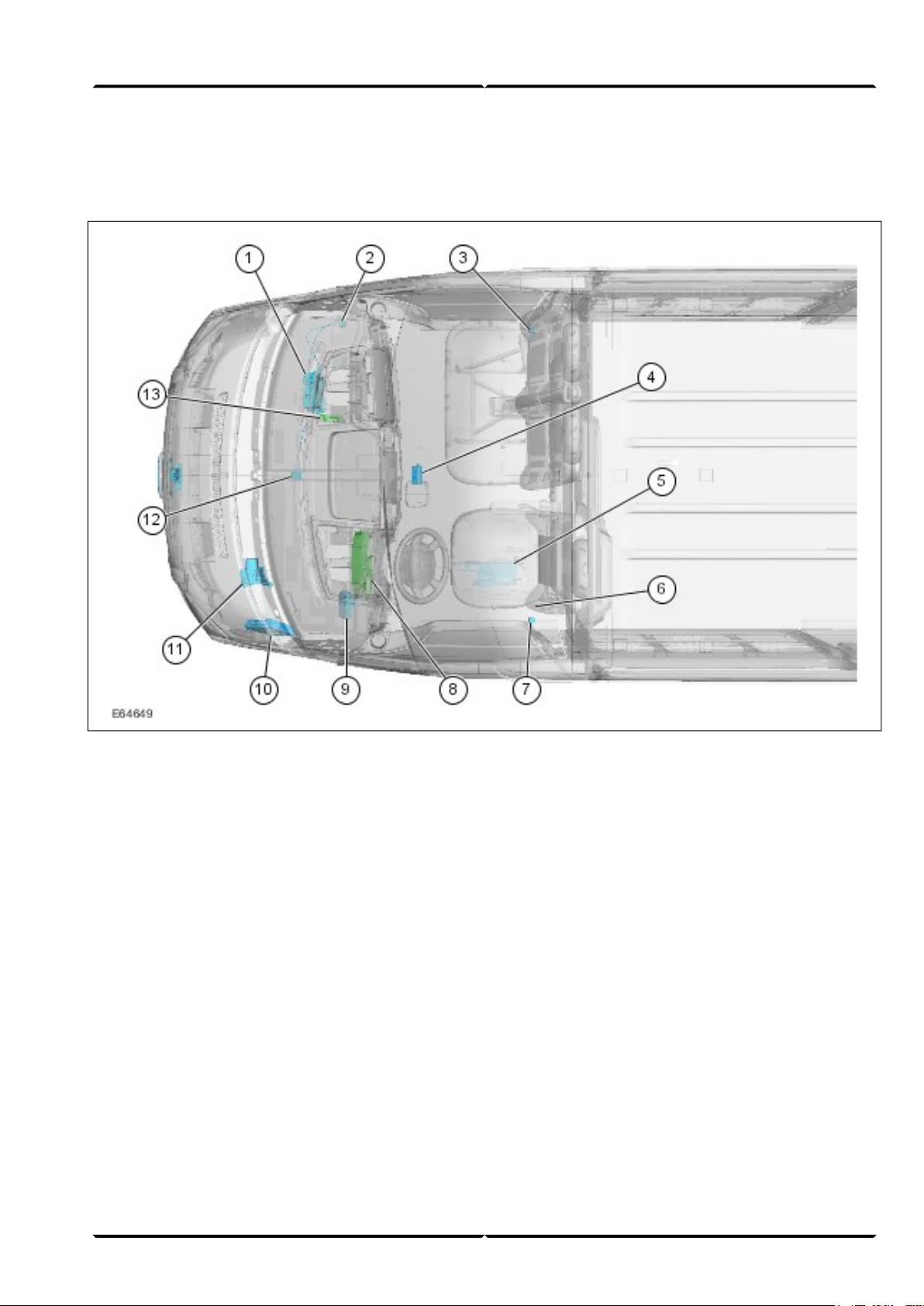
Position of electrical components
Shown: LHD (Left-hand Drive)
At a glanceIntroduction
GEM behind glove compartment, passenger side1
IFS (Inertia Fuel Shutoff) (vehicles with petrol
2
engine)
Right-hand crash sensor (with side air bag only)3
Receiver for radio remote control (in center of
4
headliner)
Booster heater (vehicle underbody, driver side)5
Trailer module (under driver seat)6
Left-hand crash sensor (with side air bag only)7
Instrument cluster8
Hands-free kit/voice control module (beside
9
instrument panel)
PCM (Powertrain Control Module) in left-hand
10
side of engine compartment
ABS (Anti-lock Brake System) module, engine
11
compartment, underneath brake master cylinder
GPS (Global Positioning System) antenna (in
12
center of instrument panel)
RCM (Restraints Control Module) (next to the
13
GEM)
7Service Training (G542739)
Page 10
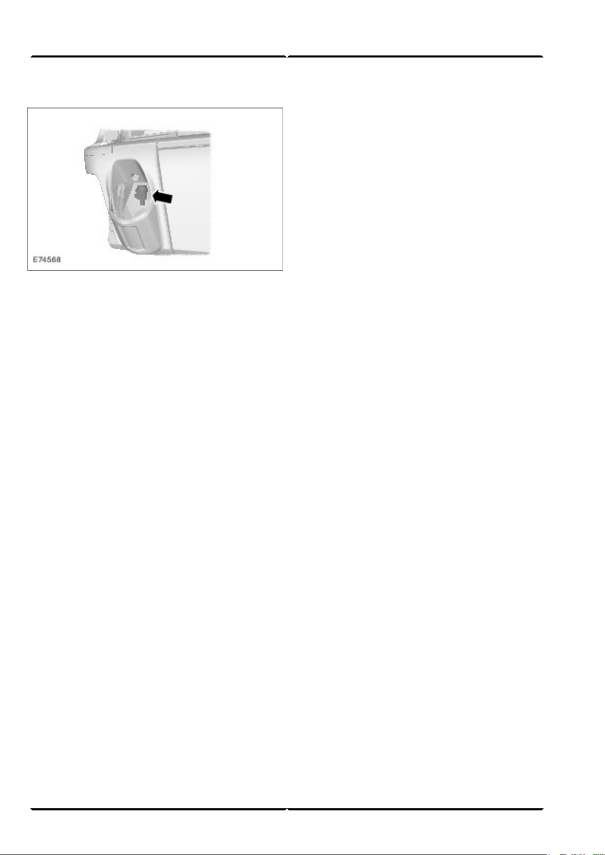
IFS switch
The IFS switch is installed in the instrument panel
(passenger side).
IntroductionAt a glance
(G542739) Service Training8
Page 11
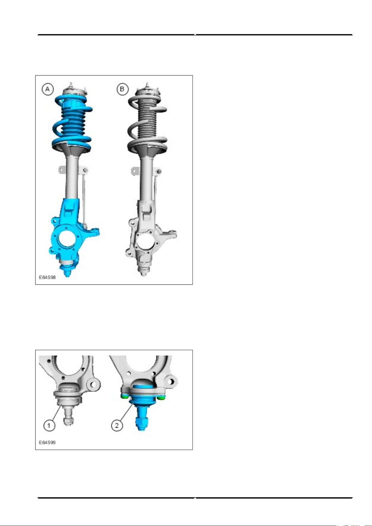
Suspension SystemLesson 2 – Chassis
Front axle
Here the ball joints are bolted between the transverse
control arm and strut and spring assembly (standard:
press-fit) and larger wheel bearings installed.
This requires a new procedure for installation and
removal. Instructions for this can be found in the
relevant Service literature.
Rear axle
In addition to modified suspension points at the rear
axle and a reinforced differential, modified final drive
ratios are also available.
V ehicles with front wheel dri ve feature a VXT75 manual
transaxle as standard with a final drive ratio of 4,23:1
or 4,54:1 depending on the payload.
Vehicles with rear wheel driv e feature f inal dri v e ratios
of 3,73:1 or 5,88:1 in conjunction with MT75 or MT82
manual transmissions.
Strut and spring assembly (reinforced front axle)A
Strut and spring assembly (standard front axle)B
In addition to the front axle installed as standard, a
reinforced version with a permissible axle load of 1,850
kg is available as an option.
Press-fit ball joint (standard front axle)1
Bolted ball joint (reinforced front axle)2
9Service Training (G542798)
Page 12
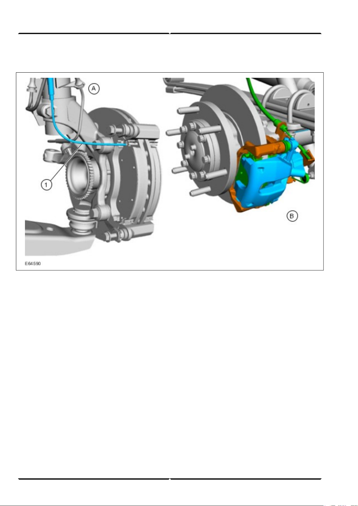
General
Lesson 2 – ChassisBrake System - General Information
Front brakeA
Rear brakeB
Brake pad wear indicator1
Larger brake discs as well as modified brake calipers
are installed on the front axle depending on the engine.
Disc brakes are installed as standard on the rear axle
(except optional version).
The rear brake calipers are similar to those in the
Mondeo 2001. The special tool 206-085 is needed to
reset the brake caliper piston.
NOTE: To reset the left-hand brake caliper piston,
apply pressure to the brake caliper piston while
simultaneously turning it counter-clockwise. To reset
the right-hand brake caliper piston, apply pressure to
the brake caliper piston while simultaneously turning it
clockwise.
All vehicles feature a brake pad wear indicator at the
disc brakes. The sensors for the brake pad wear indicator
are installed at the inner brake pads and connected in
series.
If one of the sensors is interrupted, the instrument cluster
registers a missing ground and activates a warning
indicator in the instrument cluster.
(G542740) Service Training10
Page 13
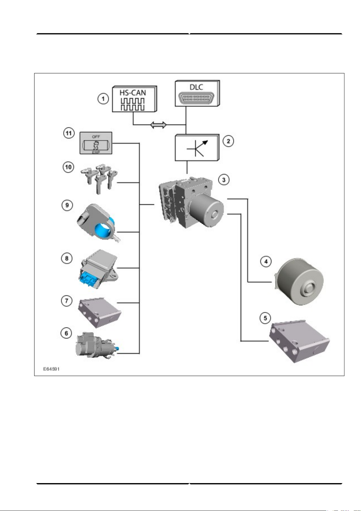
ABS system overview
Brake System - General InformationLesson 2 – Chassis
HS-CAN data bus input/output signals1
Gateway (GEM)2
ABS module3
ABS motor4
ABS/HCU (Hydraulic Control Unit).5
Stoplamp switch6
Pressure sensor (in the ABS/HCU)7
Yaw rate sensor and lateral acceleration sensor
8
(at the right-hand or left-hand foot controls)
Steering wheel rotation sensor (behind the
9
steering wheel)
Wheel speed sensors10
Stability assist switch11
11Service Training (G542740)
Page 14

Lesson 2 – ChassisBrake System - General Information
HS-CAN input signals:
1. CKP (Crankshaft Position) sensor > GEM Gateway
> ABS module
2. Engine idle speed (from PCM) > ABS module
3. Engine status (OFF, idling, stalling) (from PCM) >
ABS module
4. Duration of driving cycle (from GEM) > Gateway
> ABS module
5. Tire circumference > GEM Gatew ay > ABS module
6. Ignition lock position > GEM Gateway > ABS
module
7. Torque (from PCM) > ABS module
8. APP (Accelerator Pedal Position) position > GEM
Gateway > ABS module
9. BPP (Brake Pedal Position) switch > PCM > ABS
module
10. Parking brake switch > GEM Gateway > ABS
module
11. Outside air temperature sensor > GEM Gateway >
ABS module
12. Total mileage > GEM Gateway > ABS module
13. GEM Gateway > Instrument cluster > Data for
central vehicle configuration
HS-CAN output signals:
1. Vehicle speed signal > ABS module > GEM
Gateway
2. Intervention BTCS (Brake Traction Control System)
> ABS module > PCM
3. Torque adaptation request > ABS module > PCM
4. ABS module > GEM Gateway > Instrument cluster
> ABS warning indicator
5. ABS module > GEM Gateway > Instrument cluster
> Brake system warning indicator
6. ABS module > GEM Gateway > Instrument cluster
> ABS warning indicator
7. ABS module > GEM Gateway > Instrument cluster
> Stability assist warning indicator ESP
8. Signals of all four wheel speed sensors > ABS
module > PCM
The following brake systems are available, depending
on the vehicle version:
– ABS (Bosch 8.0)
– ABS/BTCS
– ABS/BTCS, stability assist, electronic EBA
(Emergency Brake Assist), acti ve rollover protection
Bosch 8.0 ABS system
The Bosch 8.0 ABS system is an enhancement of the
previously installed Bosch 5.3 system.
The hydraulic ABS unit and the rear brake calipers are
service pre-filled. The front brake calipers and the
cylinders of the rear drum brake are not pre-filled.
The steering wheel rotation sensor is integrated together
with the clockspring in a housing and is located behind
the steering wheel.
The steering wheel rotation sensor works according to
the principle of magnetoresistance and permits absolute
sensing of the steering wheel position.
NOTE: When replacing the sensor, make sure that the
new sensor is installed centrally and is calibrated using
WDS (W orldwide Diagnostic System). Instructions for
this can be found in the relevant Service literature.
The yaw rate/lateral acceleration sensor is
accommodated in a housing and is located on a separate
bracket to the left of the foot controls (LHD and RHD
(Right-hand Drive)).
Stability assist can be deactivated via a switch in the
instrument panel.
(G542740) Service Training12
Page 15

Active rollover protection
The active rollov er protection (ARM = Active Roll-o ver
Mitigation) is a function of the stability assist program
and is integrated as software in the – ABS/stability assist
module as standard. This function does not require any
further components.
Operation
If a sudden evasi ve maneuv er by the driv er is registered
during driving, the outside front wheel is braked for a
brief period.
Evasive maneuvers are detected by the steering wheel
rotation sensor. F or this purpose, a rotational angle speed
of more than 512 ° per second must be detected.
Brake System - General InformationLesson 2 – Chassis
The vehicle is stabilized through the braking of the
outside front wheel. The active rollover protection is
active and effects braking in a vehicle speed range
between approx. 30 and 130 km/h.
As soon as the rollover protection is activated, this is
indicated by the stability assist warning indicator in the
instrument cluster.
If the stability assist is deactivated, the rollover
protection nevertheless remains on standby.
13Service Training (G542740)
Page 16
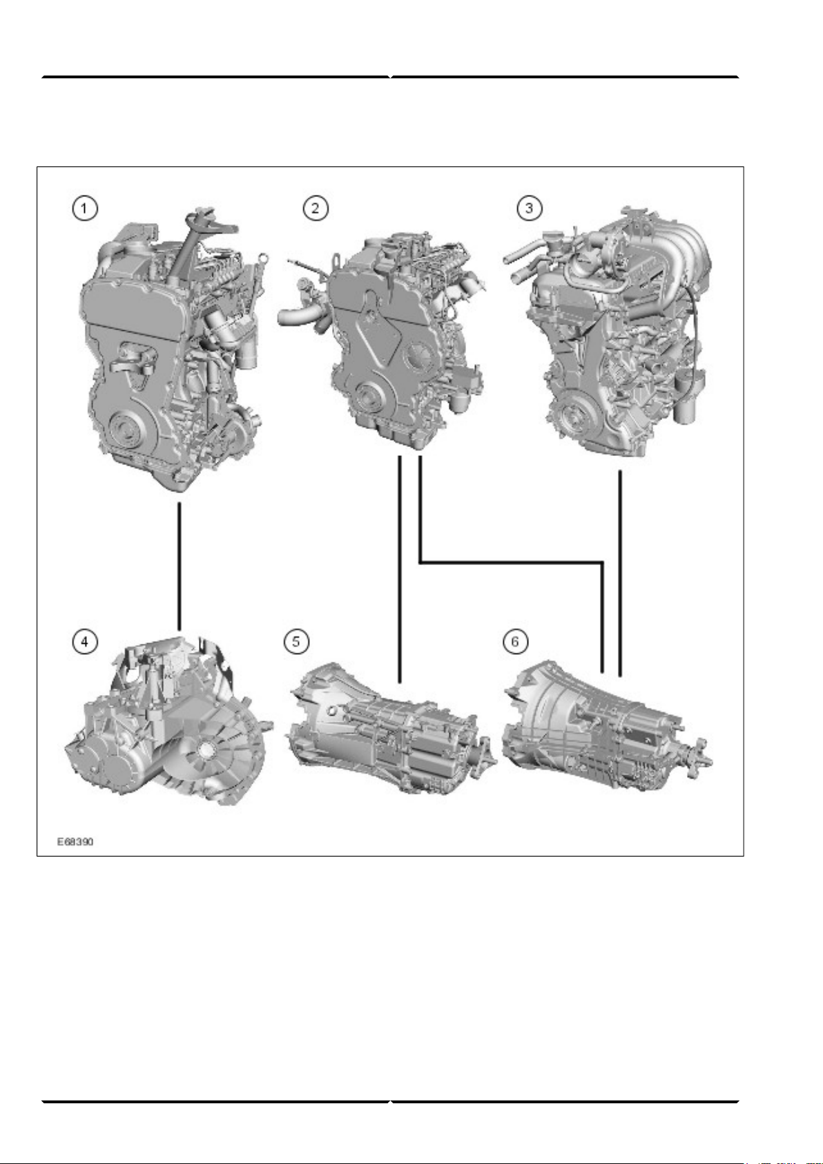
Engine/transmission combinations
Lesson 3 – PowertrainEngine System - General Information
2.2L Duratorq-TDCi (Puma) diesel1
2.4L Duratorq-TDCi (Puma) diesel2
2.3L Duratec-HE (MI4)3
VXT-75 5-speed manual transaxle4
MT82 6-speed manual transmission5
MT-75 5-speed manual transmission6
(G542741) Service Training14
Page 17

Engine System - General InformationLesson 3 – Powertrain
The Transit 2006.5 (03/2006-) is available with the
following engine/transmission combinations:
• 2.2L Duratorq-TDCi (Puma) diesel with VXT-75
5-speed manual transaxle (front wheel drive)
• 2.4L Duratorq-TDCi (Puma) diesel with MT-75
(5-speed) and MT82 (6-speed) manual transmission
(previously 2.0L)
(rear wheel drive)
• 2.3L Duratec-HE (MI4) with MT -75 5-speed manual
transmission (rear wheel drive)
The engine range consists of the following power
versions:
Torque (Nm)Power output PS (kW)Cubic capacity (drive)
25085 (63)2.2L (front wheel drive)
285110 (81)
310130 (96)
285100 (74)2.4L (rear wheel drive)
320115 (85)
375140 (103)
200145 (107)2.3L (rear wheel drive) petrol
15Service Training (G542741)
Page 18
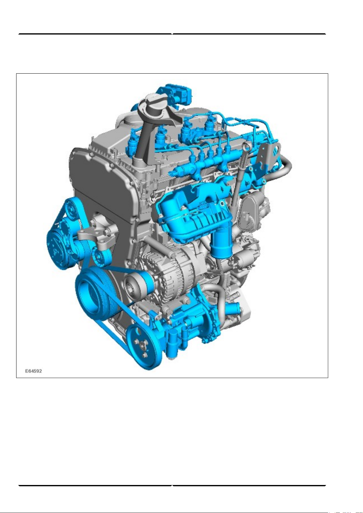
2.2L Duratorq-TDCi (Puma) diesel
Lesson 3 – PowertrainEngine System - General Information
General
• The previously installed 2.0L TDCi engine will be
replaced by a modified 2.2-liter version.
• The 2.2L Duratorq-TDCi (Puma) diesel is essentially
based on the previously installed 2.0-liter engine. It
is available in three different power output versions
of 63 kW, 81 kW and 96 kW.
• The engine features a modified valve train as well
as a modified accessory drive.
• The oil change interval is 25,000 km or one year.
• The 63 kW version is the entry-level v ersion for the
front wheel drive vehicles. A turbocharger with a
wastegate is used.
(G542741) Service Training16
Page 19

Engine System - General InformationLesson 3 – Powertrain
• The 81 kW version additionally has oil spray nozzles
for cooling the piston crown.
• The 96 kW version has a turbocharger with
electrically adjustable guide vane geometry as well
as fuel injector nozzles with an increased flow rate.
Injection system
Denso
• Fuel injectors
• High-pressure pump
• Fuel injection supply manifold
Engine management
• Visteon
• EOBD (European On-board Diagnostic) for the
monitoring of emissions-related components.
Diagnosis
• Diagnosis using WDS via the DLC (Data Link
Connector).
Engine data
2.2L Duratorq-TDCi
(Puma) diesel
Engine code
P8FA (85 PS)
QVFA (110 PS)
QWFA (130 PS)
1,998 ccmCubic capacity
86 mmStroke
86 mmBore
19 : 1Compression ratio
1-3-4-2Firing order
Engine emission control
• Meets emission standard IV
• Electrical EGR (Exhaust Gas Recirculation) valve
with water cooling
Max. power output, torque
900 rpmIdle speed
63 kW (85 PS) at 3,500
rpm, 250 Nm at 1,500 rpm
81 kW (110 PS) at 3,500
rpm, 285 Nm at 1,750 rpm
96 kW (130 PS) at 3,500
rpm, 310 Nm at 1,600 rpm
DieselFuel
17Service Training (G542741)
Page 20
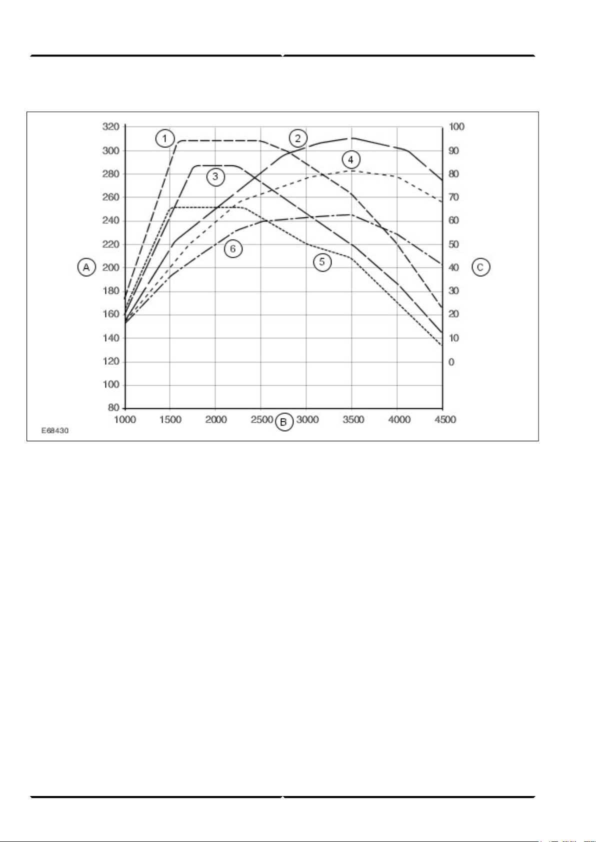
Power and torque curves
Lesson 3 – PowertrainEngine System - General Information
Torque (Nm)A
Engine speed (rpm)B
Power output (kW)C
Torque curve for 96 kW engine1
Torque curve for 81 kW engine3
Power curve for 81 kW engine4
Torque curve for 63 kW engine5
Power curve for 63 kW engine6
Power curve for 96 kW engine2
(G542741) Service Training18
Page 21
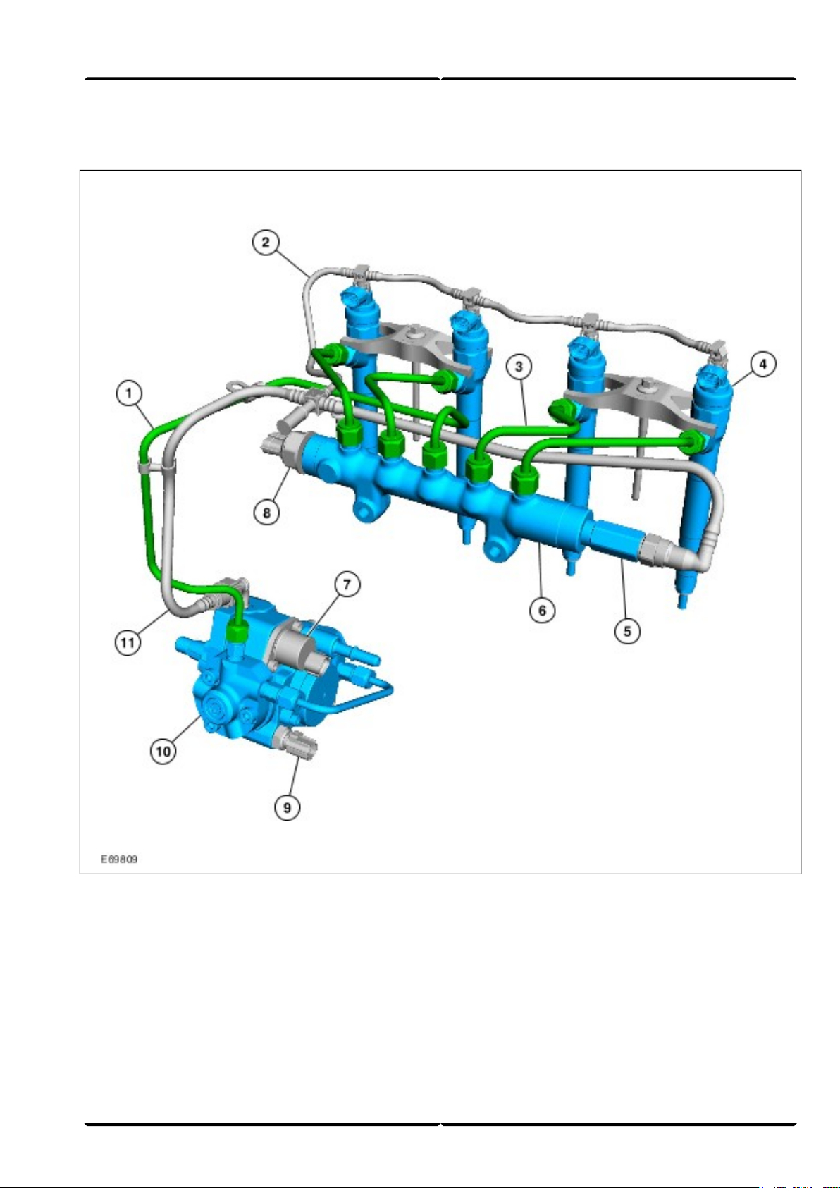
Injection system
Engine System - General InformationLesson 3 – Powertrain
High-pressure pipe1
Leak-off pipe2
Fuel injection line3
Injector4
Pressure relief valve5
Fuel injection supply manifold6
Fuel metering valve7
Fuel pressure sensor8
Fuel temperature sensor9
High-pressure pump10
Fuel return11
19Service Training (G542741)
Page 22
Lesson 3 – PowertrainEngine System - General Information
The introduction of the Transit 2006.5 (03/2006-) will
see the previously used Delphi common-rail system
replaced by the Denso common-rail system.
This has achieved an increase in engine po wer while at
the same time reducing fuel consumption.
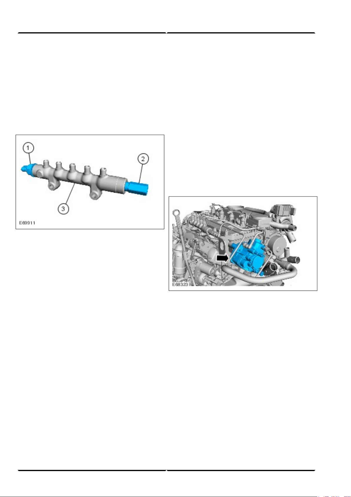
Fuel injection supply manifold
The pressure relief valve opens at a fuel pressure of
approx. 2000 bar. It serves as a safeguard in the event
of a malfunction in the high-pressure system. This
prevents damage caused by excessive fuel pressure in
the high-pressure system.
Any triggering of the pressure relief valve is detected
by the PCM, which then sets an appropriate DTC
(Diagnostic Trouble Code- WDS) and the MIL
(Malfunction Indicator Lamp) is activated.
For installation and removal, refer to the instructions in
the current Service Literature.
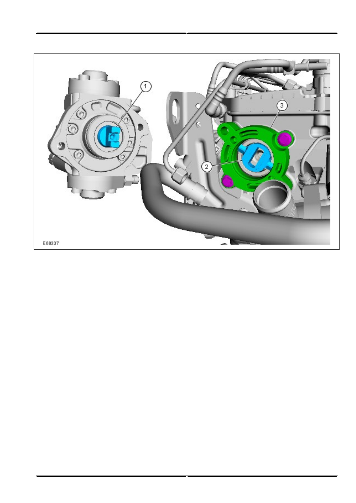
High-pressure pump
Fuel pressure sensor1
Pressure relief valve2
Fuel injection supply manifold3
NOTE: The pressure relief valve operates as a
disposable valve. This means that it must be replaced
after it has been triggered once, as the fuel-tightness of
the valve can no longer be guaranteed.
The high-pressure pump is flanged onto the left of the
cylinder head in the direction of travel and is driven by
the intake camshaft.
(G542741) Service Training20
Page 23
Engine System - General InformationLesson 3 – Powertrain
High-pressure pump coupling1
Intake camshaft coupling2
Flange for high-pressure pump3
An appropriate coupling is attached to both the intake
camshaft and the high-pressure pump for this purpose.
The instructions in the service literature must be
followed when installing the high-pressure pump.
21Service Training (G542741)
Page 24
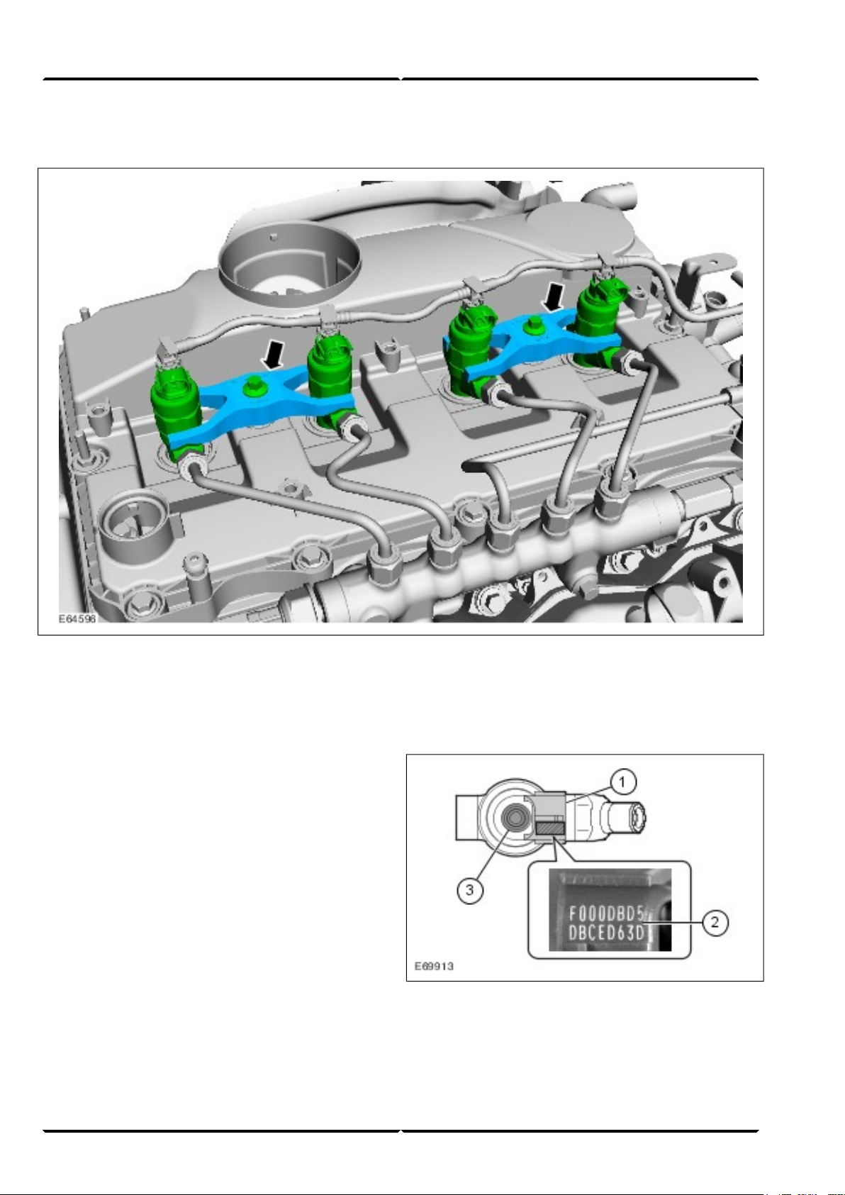
Fuel injectors
Lesson 3 – PowertrainEngine System - General Information
The fuel injectors are mounted by means of a bracket
with a central screw that fastens two nozzles at once.
It should be noted that if one of the two fuel injector
nozzles is removed, the second nozzle attached using
the common bracket must be resealed.
The associated high-pressure lines must also be replaced.
Instructions for this can be found in the relevant Service
literature.
Further information on the Denso common-rail injection
system can be found in the Student Information "Diesel
Fuel Injection and Engine Management Systems –
Common-Rail Systems", CG 8180/S.
Identification number (injector correction
factor)
Illustration shows the fuel injector from above
Electrical connection, solenoid valve1
16-digit identification number2
Connection, leak-off pipe3
(G542741) Service Training22
Page 25

Engine System - General InformationLesson 3 – Powertrain
To ensure optimum fuel metering, the PCM must be
informed when a new injector is installed.
Furthermore, after new PCM software has been loaded
via WDS, the injectors must also be configured.
This is achieved by entering the 16-digit identification
number into the PCM using WDS, taking into account
the relevant cylinder.
Note: If the identification numbers are not entered
properly with WDS, the following faults can occur:
• Increased black smoke formation,
• Irregular idling,
• Increased combustion noise.
Valve train
The valve train has been adapted to the ne w position of
the high-pressure pump. The timing chain now only
drives the two camshafts. Consequently, the housing as
well as the routing of the timing chain have been
modified.
23Service Training (G542741)
Page 26

Accessory drive
Lesson 3 – PowertrainEngine System - General Information
Accessory drive without A/C (Air Conditioning)
A
compressor
Accessory drive with A/C compressorB
If air conditioning is installed, the accessory drive belt
of the A/C compressor is tensioned via a timing belt
tensioner. If there is no air conditioning installed, the
accessories are driven by two self-tensioning
multigroove belts.
Tensioner1
Tensioning rollers2
(G542741) Service Training24
Page 27

Engine System - General InformationLesson 3 – Powertrain
Power steering pump1
Coolant pump2
The coolant pump is located on the front of the engine
and is flanged on directly behind the power steering
pump. Both pumps are connected by means of a shaft
and driven via a pulley.
The pumps can be replaced separately during servicing.
Instructions for this can be found in the relevant Service
literature.
25Service Training (G542741)
Page 28

Cylinder head
Lesson 3 – PowertrainEngine System - General Information
Oil baffle plate1
Aluminum support2
The mounting as well as the oil supply of the rocker
arms has been modified. The pre viously installed rocker
shafts have been discontinued. The rock er arms are now
mounted on a separate aluminum support.
(G542741) Service Training26
Page 29

Engine System - General InformationLesson 3 – Powertrain
Hydraulic valve clearance compensation1
Rocker arms2
The components for hydraulic valve clearance
compensation are integrated in the rocker arms. The
changes to the procedure for assembly/disassembly of
the cylinder head are described in the relevant service
literature.
27Service Training (G542741)
Page 30

Lesson 3 – PowertrainEngine System - General Information
Cylinder block
2.4L Duratorq-TDCi (Puma) diesel
General
• The 2.4L Duratorq-TDCi (Puma) diesel engine is
essentially based on the previously installed 2.4-liter
engine. It is available in three dif ferent power output
versions of 74 kW, 85 kW and 103 kW.
• Like the 2.2-liter version, the engine features a
modified valve train as well as a modif ied accessory
drive.
• The introduction of the Transit 2006.5 (03/2006-)
will see the previously used Delphi common-rail
system replaced by the Denso common-rail system.
– The fuel injection pump is still driven by the
timing chain of the valve train.
• The service interval is 25,000 km or one year for all
versions other than the 103 kW version.
The cylinder block has been modified. One significant
change in comparison with the 2.0L Duratorq-TDCi
(Puma) diesel engine is the omission of the bearings for
the balance shafts.
This modifies the reference point for installation of the
reinforcing frame between the engine block and oil pan.
Please refer to the relevant Service literature for
instructions on installing the reinforcing frame.
• The service interval for the 103 kW version is 50,000
km or two years. A service interval indicator in the
instrument cluster alerts the driver when servicing
is required.
• The 74 kW version is the entry-level v ersion for the
rear wheel drive vehicles.
• The 85 kW version additionally has oil spray nozzles
for cooling the piston crown as well as fuel injector
nozzles with an increased flow rate.
• The 103 kW version has an electrical actuator for
turbocharger guide vane adjustment, an oil
level/temperature sensor and a centrifugal oil filter.
Injection System
Denso
• Fuel injectors
• High-pressure pump
• Fuel injection supply manifold
(G542741) Service Training28
Page 31

Engine System - General InformationLesson 3 – Powertrain
Engine management
• Visteon
• EOBD for the monitoring of emissions-related
components.
Engine emission control
• Meets emission standard IV
• Electrical EGR valve with water cooling
Diagnosis
• Diagnosis using WDS via the DLC
Engine data
2.4L Duratorq-TDCi
(Puma) diesel
Engine code
Max. power output, torque
PHFA (100 PS)
JXFA (115 PS)
H9FB (140 PS)
2,402 ccmCubic capacity
94.6 mmStroke
89.9 mmBore
19:1Compression ratio
1-3-4-2Firing order
900 rpmIdle speed
74 kW (100 PS) at 3,500
rpm, 285 Nm at 1,600 rpm
85 kW (115 PS) at 3,500
rpm, 310 Nm at 1,750 rpm
103 kW (140 PS) at 3,500
rpm, 375 Nm at 2,000 rpm
DieselFuel
29Service Training (G542741)
Page 32

Power and torque curves
Lesson 3 – PowertrainEngine System - General Information
Torque (Nm)A
Engine speed (rpm)B
Power output (kW)C
Torque curve for 103 kW engine1
Torque curve for 85 kW engine3
Power curve for 85 kW engine4
Torque curve for 74 kW engine5
Power curve for 74 kW engine6
Power curve for 103 kW engine2
(G542741) Service Training30
Page 33

Centrifugal oil filter (140 PS version only)
Engine System - General InformationLesson 3 – Powertrain
Cover1
Centrifuge (under the valve cover)2
Oil pressure line to the centrifugal oil filter3
The 103-kW version of the 2.4L Duratorq-TDCi (Puma)
diesel engine features a centrifugal oil filter. In
conjunction with a calculation algorithm in the PCM
and an additional oil level/temperature sensor, this
permits a service interval of up to 50,000 km.
The centrifugal oil filter is located in the cylinder head
and comprises:
• a cover cap (in the valve cover)
• a replaceable rotor (centrifuge)
The oil from the oil pan is pumped into the rotor via an
additional pressure line installed on the outside of the
engine block. Inside the rotor is a pivot axis with two
outlet openings on opposite sides.
The oil pressure and the shape of the rotor cause this
pivot axis to turn, forcing the oil in the rotor outwards.
The centrifugal force presses the particles floating in
the oil (contamination particles) against the outer wall
of the rotor, where they form a solid mass.
The oil in the rotor is filtered in this manner and then
flows back into the oil circuit.
The centrifugal oil filter can even catch small particles
of dirt that cannot be filtered using normal oil filters.
This increases the service life of the oil.
31Service Training (G542741)
Page 34

Oil level/temperature sensor (103 kW version only)
Lesson 3 – PowertrainEngine System - General Information
Oil level/temperature sensor1
Openings2
Oil dipstick3
An oil level/temperature sensor located on the front of
the engine directly beside the engine oil dipstick is
provided for the service interval indicator.
The oil level is measured by means of a wire coil located
inside the sensor. A continuous current is applied to this
wire coil.
The resistance and consequently the voltage drop at the
wire coil changes according to how deeply the sensor
is immersed in the oil. The measured values are
registered by the PCM.
The change in the voltage drop serves as an input
variable for calculation of the oil level.
The oil temperature is simultaneously sensed via the
integrated temperature sensor. The temperature is used
as a correction factor in the calculation.
The PCM calculates the next oil change on the basis of
an integrated strategy (which also takes into account
the mileage and engine operating conditions) and
displays it in the instrument cluster.
In addition, a separate indicator in conjunction with a
corresponding message in the instrument cluster display
warns the driver when the oil quantity falls below the
minimum level.
(G542741) Service Training32
Page 35

Engine System - General InformationLesson 3 – Powertrain
Service instructions
The interval indicator must be reset after an oil change
2.3L Duratec-HE (MI4)
on all vehicles with a diesel engine.
Please refer to the relevant Service literature for a
description of this procedure.
The 2.3L Duratec-HE (MI4) engine is essentially based
on the 2.0L Duratec-HE (MI4) already used in the Focus
C-MAX 2003.75 and 2004.75 Focus.
33Service Training (G542741)
Page 36

Lesson 3 – PowertrainEngine System - General Information
The main features of the engine are as follows:
• Longitudinally installed four-cylinder in-line engine
with two chain-driven overhead camshafts and 16
valves
• Aluminum cylinder block with lower crankcase
• Mechanical bucket tappets
• Intake manifold runner control with swirl flaps
• Ignition system with ignition coil-on-plug
• Electronic throttle valve
• Balance shafts
Engine management
• Visteon PCM
• Knock control with one KS (Knock Sensor)
Engine emission control
• Meets European emission standard IV
• EOBD for the monitoring of emissions-related
components.
Engine data
2.3L Duratec-HE (MI4)
Engine code
Max. power output
GZF A (emission standard
IV)
GZFB (emission standard
III)
2,261 ccmCubic capacity
94 mmStroke
87.5 mmBore
9.7:1Compression ratio
1-3-4-2Firing order
rpmIdle speed
107 kW (145 PS)
at 5,250 rpm
210 Nm at 3,750 rpmMax. torque
Diagnosis
• Diagnosis using WDS via the DLC
Premium 95 RONFuel
(G542741) Service Training34
Page 37

Power and torque curve (when using 95 RON fuel)
Engine System - General InformationLesson 3 – Powertrain
Torque (Nm)A
Engine speed (rpm)B
Power output (kW)C
Service instructions
The valve clearance of the engine only needs to be
monitored if the engine is converted to operation using
alternative fuel (every 60,000 km).
Conversion of the engine to operation with alternative
fuel requires no modification to the engine as the valve
seats are reinforced as standard. All that is required is
an adaptation of the fuel system.
The service interval is 20,000 km or one year.
35Service Training (G542741)
Page 38

Accessory drive
Lesson 3 – PowertrainEngine System - General Information
Accessory drive with A/CA
Accessory drive without A/CB
For further information on the engine, please refer to
the following Student Information publications:
• New Product Information TN7002114S, Mondeo
2001, 1.8L and 2.0L Duratec-HE Petrol Engines,
CG 7870/S
• New Product Information TN7002142H, Focus
C-MAX 2003.75 (06/2003-), CG 8037/S
• New Product Information TN7002151H, Focus
2004.75 (07/2004-), CG 8144/S
(G542741) Service Training36
Page 39

Transmission
Shift mechanism
Engine System - General InformationLesson 3 – Powertrain
A new special tool 308-650 is available for adjusting
the gearshift mechanism on all transmissions.
Please refer to the relevant Service literature for
instructions on adjusting the gearshift mechanism.
The gearshift lever is located on the instrument panel.
The reverse gear lock is overcome by lifting a
ring-shaped securing lever (previously knock-over
function).
A gearshift mechanism with control cable is used for
the first time for the rear wheel drive versions with
MT75 and MT82 manual transmissions.
Clutch assembly
All rear wheel drive versions as well as the VXT75
manual transaxle in conjunction with the 96 kW
Duratorq TDCi engine are equipped with a dual mass
flywheel (LUK).
37Service Training (G542741)
Page 40

Overview
Lesson 4 – ElectricalInstrument Cluster
HS-CAN data bus1
MS-CAN data bus2
Gateway (GEM)3
Instrument cluster module4
Displays in the instrument cluster5
Multifunction switches ("set/reset" button, rotary
6
switch)
Digital tachograph7
Brake pad wear indicator8
(G542742) Service Training38
Page 41

Instrument ClusterLesson 4 – Electrical
HS-CAN input signals:
1. CKP sensor > GEM Gateway > Instrument cluster
> Tachometer
2. Wheel speed sensor > ABS module > GEM Gateway
> Instrument cluster > Vehicle speed display (VSS
(Vehicle Speed Sensor))
3. ABS module > GEM Gateway > Instrument cluster
> Brake system warning indicator
4. ABS module > GEM Gateway > Instrument cluster
> ABS warning indicator
5. ABS module > GEM Gateway > Instrument cluster
> Stability assist warning indicator ESP
6. PCM-controlled battery charge > Generator > GEM
Gateway > Instrument cluster > Charging system
warning indicator
7. PCM > GEM Gateway > Instrument cluster > Glow
plug warning indicator (vehicles with diesel engine)
8. ECT (Engine Coolant Temperature) sensor > PCM
> GEM Gateway > Instrument cluster > Temperature
display
9. PCM > GEM Gateway > Instrument cluster > Speed
control system warning indicator
10. PCM > GEM Gateway > Instrument cluster > MIL
warning indicator
11. PCM > GEM Gateway > Instrument cluster >
Powertrain warning indicator or display in the
message center
12. Oil pressure switch > PCM > GEM Gateway >
Instrument cluster > EOP (Engine Oil Pressure)
warning indicator
13. Oil level/temperature sensor > PCM > GEM
Gateway > Instrument cluster > Engine oil level
warning indicator or oil change warning in message
center display
MS-CAN input signals:
1. Ignition lock position > GEM Gateway > Instrument
cluster (power management)
2. Reversing lamp switch > GEM Gateway >
Instrument cluster
3. Time > GEM Gatew ay > T ime display in instrument
cluster (with RDS 1500 or without radio)
4. Alarm time > GEM Gateway > Instrument cluster
5. Brake fluid level sensor GEM Gate way > Instrument
cluster > Parking brake warning indicator
6. Water-in-fuel sensor > GEM Gateway > Instrument
cluster > Warning LED (Light Emitting Diode)
7. Outside air temperature sensor > GEM Gateway >
Instrument cluster > Ice warning indicator or
temperature gauge in the display in the message
center
8. RCM > Instrument cluster > Air bag warning
indicator or safety belt warning indicator
9. Headlamp switch > GEM Gateway > Instrument
cluster > Lighting indicator or light-on warning tone
10. PATS transceiver > GEM Gateway > Instrument
cluster > PATS indicator
11. Door contact/hood switch > GEM Gateway >
Instrument cluster > Door warning indicator or door
status display in the message center
12. GEM Gateway > Instrument cluster > Data for
central vehicle configuration
13. Fuel level sensor > GEM Gateway > Instrument
cluster > Tank display or fuel reserve warning
indicator
MS-CAN output signals:
1. Instrument cluster > GEM Gateway > ABS module
> Mileage
2. Instrument cluster > Audio unit > Vehicle speed
signal
3. Instrument cluster > Audio unit > Reverse gear signal
39Service Training (G542742)
Page 42

Lesson 4 – ElectricalInstrument Cluster
4. Instrument cluster > Audio unit > T ime display (not
with RDS 1500)
Operation
Shown: Low equipment level
5. Instrument cluster > DLC
PATSLED1
Brake pad wear warning indicator2
Trip odometer reset button (not with high
3
equipment level)
The instrument cluster is available in two versions
depending on the vehicle equipment. The version with
high equipment level has a full dot-matrix display as
well as an info LED between the large analog displays.
Messages are shown in the instrument cluster via the
display and the LED. The LED lights up yellow or red
according to the significance of the message.
Time setting button (not with high equipment
4
level)
Multi-function display5
Service reminder indicator6
The instrument cluster is connected to the MS-CAN bus
and forms the interface between the MS-CAN bus of
the audio system and the MS-CAN bus of the rest of
the module communications network. It contains three
120 Ohm terminating resistors; two for the audio
network and one for the rest of the MS-CAN network.
(G542742) Service Training40
Page 43

The instrument cluster is part of the central vehicle
configuration and saves the conf iguration data of all the
modules stored in the GEM. However, this data serves
only as a backup copy in the event that the GEM needs
to be replaced.
It is not possible to change and/or enter the mileage
following replacement. The original mileage will be
automatically read in and saved via the central vehicle
configuration.
Configuration of the message center (high
equipment level)
By pressing the "Set/Reset" buttons on the steering
column control lever, a sub-menu can be selected or a
setting can be changed.
Instrument ClusterLesson 4 – Electrical
By operating the rotary switch on the steering column
lever, you can scroll through the displays within a
particular menu.
Diagnostics
The instrument cluster can be diagnosed using the WDS.
Observe the instructions on module configuration when
replacing the instrument cluster.
41Service Training (G542742)
Page 44

Lesson 4 – ElectricalTachograph
General
A digital tachograph (Siemens VDO, type DTCO 1381)
is available for the Transit 2006.5.
This tachograph works with the aid of chip cards which
store all the necessary information. These chip cards
are driver-specific and must be inserted in the card
reader before departure.
The tachograph registers
• driving, working and rest times for the driver and
passenger,
• speed (24 hours in mass memory) and distance
driven,
• operation-specific parameters such as speed, other
work operations on the vehicle and events such as
information on calibration and/or periodic testing.
The data is stored:
• vehicle-specifically in an integrated mass memory
unit with capacity for recording the activities for
approx. 365 days
• driver-specifically on the personal driver card with
capacity for approx. 28 days
A separate VSS that transmits a digitally encrypted
signal directly to the tachograph is installed at the
transmission during installation of the tachograph.
The data of two drivers can be registered in parallel
using two chip-card readers. Further instructions on
operation can be found in the relevant Owner's
Handbook.
The tachograph in 1-DIN radio format is installed above
the instrument panel and includes
• two chip-card readers,
• an integrated printer for creating logs for drivers and
inspectors,
• a display containing important information, e.g. on
the current driving and rest-period account,
• a real-time clock,
• various controls.
The sensor is secured against tampering by a lead seal.
Installation and calibration of the system is carried out
by authorized service partners.
The tachograph is supplied with separate operating
instructions (from Siemens).
Diagnosis can only be carried out by authorized dealers.
Note
The introduction of digital tachographs in commercial
vehicles with a permissible gross weight of more than
3.5 tons and vehicles with more than nine seats came
into force on August 5, 2005 (European Legislation
EEC No 3820/85 and 3821/85).
Digital tachographs have been permitted on new v ehicles
since mid-2005. It must be noted here that digital
tachographs may only be diagnosed and/or repaired by
authorized Siemens dealers. Further instructions on this
can be found in TSB 59/2005.
Further information at "http://www.vdo.com"
(G542799) Service Training42
Page 45

Overview
Audio SystemLesson 4 – Electrical
MS-CAN data bus1
Gateway (instrument cluster)2
Audio/navigation unit3
Right-hand speaker4
Left-hand speaker5
Hands-free system/Bluetooth/voice control
6
module
Audio remote control7
GPS/GSM (Global System for Mobile
Communication)/AM (Amplitude
8
Modulation)/FM (Frequency Modulation)
antenna
43Service Training (G829488)
Page 46

Lesson 4 – ElectricalAudio System
MS-CAN input signals:
1. Vehicle speed signal > Wheel speed sensor > ABS
module > GEM Gateway (MS-CAN) > Instrument
cluster gateway > Audio unit
2. Ignition lock > GEM Gateway > Instrument cluster
gateway > Audio unit
3. Reversing lamp switch > GEM Gateway >
Instrument cluster gateway > Audio unit > Reverse
gear signal
4. Microphone > Bluetooth/voice control module >
audio system
MS-CAN output signals:
1. Instrument cluster gateway > Audio unit > Time
display/setting (not with RDS 1500)
2. Audio unit > Bluetooth/voice control module
3. Audio remote control > Audio unit > Bluetooth/voice
control module
General
All multimedia devices (audio units, navigation de vices
and hands-free kit) are connected to each other via a
separate MS-CAN network (audio network).
The instrument cluster, which acts as a gate way between
the audio network and the rest of the MS-CAN network,
enables the following functions:
• Time (from the GEM to the audio unit)
• Setting time (from the audio unit to the GEM)
• Vehicle speed information
• Reverse gear information
• Diagnostics
• Clear module
• Central module configuration
The new generation of audio units is available in the
following versions for the Transit:
• 1500 RDS
• 6000 CD
• 6006 CDC
(G829488) Service Training44
Page 47

1500 RDS
Audio SystemLesson 4 – Electrical
1500 RDS, RDS, 2 X 6 watt output, not connected to
the MS-CAN bus
45Service Training (G829488)
Page 48

6000 CD
Lesson 4 – ElectricalAudio System
6000 CD (Compact Disc), larger display, CD player, 4
x 17 Watt output, Bluetooth-compatible
(G829488) Service Training46
Page 49

6006 CDC
Audio SystemLesson 4 – Electrical
6006 CDC, as 6000 CD, with integrated 6-disc changer
Radio remote control is available for certain equipment
levels (same as Focus/Focus C-MAX).
The time is shown in the display of all units with the
exception of the 1500 RDS. The radio display serves
exclusively to show and set the time. The actual clock
is located in the GEM.
For vehicles equipped with 1500 RDS or vehicles
without radio, the time is displayed in the instrument
cluster.
It is not possible to display the RDS time in the audio
unit (deactivated in the radio software).
Function changes compared with the devices installed
in the Focus 2004.75 and Mondeo 2001 (does not apply
to 1500 RDS):
• Separate CLOCK button
• No PTY function
• REG function can be disabled
• No frequency display when the station name appears
One significant change to the 6000 CD and 6006 CDC
in comparison with the units installed in the Focus and
Mondeo is the discontinuation of the program type code
(PTY) function. The PTY button has been replaced by
a new phone button bearing a handset symbol instead
of the inscription "PHONE".
The phone button has been replaced by a button with
the inscription "CLOCK" for setting the time. This
makes it easier to set the time by means of direct access
to the appropriate menu.
In addition, all audio units feature a modified anti-theft
protection system. This system works on the basis of
the VIN (Vehicle Identification Number) identif ication
rather than entry of a key code (see also central vehicle
configuration).
47Service Training (G829488)
Page 50

Instructions about the function and operation of the
audio units can be found in the Owner's Handbook
"Audio", CG3454 or 6S6J-19C104-HA 10/2005
20050920142621.
VIN locking function
A new type of anti-theft protection is being introduced
during production.
The VIN is, as was the case previously, transmitted to
the audio unit via the MS-CAN bus and saved in the
unit while still in the factory.
Howev er, the keycode function is disabled, and instead
the VIN of the audio unit is read in and checked every
time the ignition is switched on.
Lesson 4 – ElectricalAudio System
As soon as the audio unit is correctly identified when
the ignition is switched on (even when the battery has
been disconnected), it can be operated without any
further input.
If an audio unit whose VIN does not match that of the
vehicle is identified, the audio unit remains disabled.
It is not possible to manually enter or change the VIN.
Installing a previously configured unit (with sa ved VIN)
in another vehicle requires access to OASIS (On-line
Automotive Service Information System) in conjunction
with WDS.
(G829488) Service Training48
Page 51

Travel Pilot EX
Navigation SystemLesson 4 – Electrical
A factory-installed navigation system is av ailable in the
Transit for the first time. The Travel Pilot EX
corresponds in function to the unit available in the Focus
2004.75 (11/2004-) and offers the following features:
• 4 x 20 W output power
• Large 4-inch monochrome display
• MP3-compatible CD drive
• Bluetooth-compatible
• Turn-by-turn navigation (displays the street names
even if no route is calculated)
• Corridor function (additional area either side of the
route. In this corridor, the system takes into account
the most up-to-date traffic information).
• Voice output without navigation CD-ROM (in
conjunction with corridor function)
• Navigation CD with detailed and additional data
• Simulation mode can be activated/deactivated
directly from the Menu button
• The designation "RNS" has been dropped, no
reference to the manufacturer
NOTE: When installing a new navigation unit, the
navigation unit must be configured by selecting the
routine "Install programmable modules" in WDS.
Further information on operation is provided in the
Owner's Handbook CG 3474.
Service instructions
The Travel Pilot EX can be diagnosed using two
different menus:
• Tuner test mode
• Dealer service mode
49Service Training (G829489)
Page 52

Lesson 4 – ElectricalNavigation System
DescriptionButton combination
Tuner test modeS1 + MENU
S4 + MENU
Dealer service mode
FM steps: This sets the size of the steps for the station search, usually 100 kHz, 50
kHz when cable connected in demo stand.
Version: Displays different versions (hardware, software, CD-ROM (Read Only
Memory))
Display test: Different patterns are shown on the display, enabling individual faulty
pixels to be detected
Faults: Stored diagnostic trouble codes are displayed here; this item cannot be
selected if no faults are stored
Navigation download: Loads the navigation software from the CD-ROM into the
unit's memory
System download: Loads the system software from the CD-ROM into the unit's
memory
GPS information: Displays the latitude and longitude for the current position and
the number of satellites received
CD eject:Allows the CD eject button to be locked (e.g. for hire cars, demonstration
units, etc.)
System test: Different tests can be selected, the sensor test is important for service
All menus are exited when the unit is switched off or
the "ESC" (Escape) button is pressed when in the main
menu. The revised settings will then be stored.
Some of the information available in the dealer menu
can also be retrieved by pressing the NAV button and
then the preset button S5 or S6 (in the EXTRA display).
A diagnostic trouble code table is contained in FordEtis,
Group 419-07B.
(G829489) Service Training50
Page 53

General
Cellular PhoneLesson 4 – Electrical
MS-CAN data bus input/output signals1
Gateway (instrument cluster)2
Hands-free system/Bluetooth/voice control
3
module
Audio/navigation unit4
Cellular phone5
GSM antenna6
Handset holder7
Microphone8
51Service Training (G829490)
Page 54

A factory-installed hands-free kit is available in the
Transit for the first time.
Three types of system are available regardless of the
audio unit installed:
A. Hands-free kit with handset holder
B. Hands-free kit without handset holder, with
Bluetooth and voice control
C. Hands-free kit with handset holder, Bluetooth and
voice control
With all versions, voice output is via the vehicle
loudspeakers. The function of the system essentially
corresponds to that in the Mondeo 2001 (06/2003-),
Focus C-MAX 2003.75 (06/2003-) and Focus 2004.75
(07/2004-). Further information is provided in the
training literature "Infotainment – Fundamentals"
TC4012031H, CG 8140/S and "Infotainment – Service
and Diagnosis" TC4012032H, CG8141/S and in the
Owner's Handbook CG3527.
Lesson 4 – ElectricalCellular Phone
MS-CAN input signals:
1. Audio remote control > Audio unit > Bluetooth/voice
control module
2. Station buttons > Audio unit > Bluetooth/voice
control module
MS-CAN output signals:
1. Microphone > Bluetooth/voice control module >
Audio unit
2. Microphone > Bluetooth/voice control module >
Navigation system
(G829490) Service Training52
Page 55

Exterior LightingLesson 4 – Electrical
General
The low beam switch-off delay feature, when acti vated,
keeps the side lamps, the low beams and the
number-plate lamp on for approx. 30 seconds after the
last door is closed (this can be extended to max. 180
seconds through configuration).
If a vehicle door or the liftgate is opened, the switch-off
delay is increased to 180 seconds. After the last door
has been closed, the switch-off time is reset to 30
seconds.
The dipped beam switch-off delay function is
deactivated:
• when the ignition is switched on
• by pressing the high-beam lever again
The autolamp feature works in the same way as on the
Mondeo 2001 (06/2003-), Focus C-MAX 2003.75
(06/2003-) and Focus 2004.75 (07/2003-).
The mounting points of the headlamps have changed
on account of the redesign of the headlamps.
In order to install new bulbs, the headlamp must be
removed. Please refer to the Service literature for
instructions.
In addition to the normal functions, the following
functions are also available:
• Low beam switch-off delay
• Autolamps (in conjunction with rain sensor)
The low beam switch-off delay feature is activated by
pressing the high-beam lever when the ignition key is
in position "0". Activation is confirmed by a short
audible signal.
All models with the exception of the flatback versions
feature a high mounted stoplamp. The design of the rear
lights has been modified through the use of a clear-glass
cover.
Also integrated is a one-touch turn signal function, i.e.
briefly touching the direction indicator control triggers
three short flashes of the turn signal.
53Service Training (G542744)
Page 56

Overview
Lesson 4 – ElectricalCommunications Network
MS-CAN data busA
ISO 9141B
Outgoing/incoming lines (RX/TX)C
LIN data busD
HS-CAN data busE
SRS (Supplemental Restraint System) module1
Phone / Bluetooth/voice control module2
Instrument cluster3
Audio unit4
Parking aid module5
GEM6
Light/rain sensor7
Radio remote control reception module8
PATS transceiver unit9
Battery-buffered anti-theft alarm system horn
10
(BBS)
Passenger compartment control sensor(s)11
PCM12
ABS module13
Steering wheel rotation sensor14
Yaw rate/lateral acceleration sensor15
DLC16
Terminating resistors17
(G542745) Service Training54
Page 57

Communications NetworkLesson 4 – Electrical
Up to four data bus systems can be used in the Transit
2006.5 depending on the model and equipment:
• HS-CAN bus
• MS-CAN bus
• ISO 9141 protocol
• LIN (Local Interconnect Network)
All systems can be diagnosed via the DLC.
The following modules are implemented as gateways:
– GEM Gateway between the HS-CAN and the central
electrics MS-CAN
– Instrument cluster gateway between the central
electrics MS-CAN and the audio system MS-CAN
.
HS-CAN
The following systems are connected to the HS-CAN
bus:
• ABS
– Steering wheel rotation sensor
– Yaw rate/lateral acceleration sensor
Fuel fired booster heater–
– RCM
– Parking aid module
– Instrument cluster
2. MS-CAN for the audio system
– Instrument cluster
– Audio system
– Bluetooth/voice control module
Here, the instrument cluster acts as a gateway to the
MS-CAN network of the audio system. This gateway
provides the information required for the audio system
and the Bluetooth/voice control module (see the
description of the audio systems).
This eases the data transfer load on the remaining
MS-CAN network and reduces potential sources of
faults.
The two terminating resistors, each of 120 ohm, of the
MS-CAN data bus are integrated into the GEM and into
the instrument cluster. The total resistance of the central
electrics MS-CAN amounts to 60 ohms, measured at
the DLC.
• PCM
• GEM (Gateway to the HS-CAN)
The two terminating resistors, 120 Ohm each, of the
HS-CAN data bus are integrated into the PCM and the
GEM.
Given the fact that both 120-ohm resistors are connected
in parallel, the total resistance is 60 ohms (measured at
the DLC). When a control module is disconnected, 120
ohms must be measured at the DLC.
MS-CAN
T wo separate MS-CAN networks are used in the T ransit:
1. MS-CAN for all systems apart from the audio
system:
The two terminating resistors of the MS-CAN audio
system are installed together in the instrument cluster.
As this network is not connected to the DLC, the total
resistance cannot be measured at the DLC.
ISO
The following systems are connected using the
ISO-9141 protocol:
• Receiver for radio remote control
• PATS transceiver
• Light/rain sensor
55Service Training (G542745)
Page 58

LIN bus
The following systems are connected to the LIN bus
(only for vehicles with Thatcham CAT 1 alarm and
closed driver cab):
• Ultrasonic sensors
• Battery-buffered alarm horn
LIN is a standard specifically designed for cost-effecti ve
communication between intelligent sensors and actuators
in vehicles. It is used wherever the bandwidth and
versatility of a CAN are not required.
Within a LIN bus the transfer rate can reach up to 20
kbit/s. On the Transit, the speed is approx. 9,600 baud
(9.6 kbit/s).
Lesson 4 – ElectricalCommunications Network
A LIN network comprises a LIN master and one or more
LIN slaves. The LIN master, which is the GEM in the
case of the Transit, has information on the temporal
sequence of all the data to be transmitted.
This data is transmitted by the relevant LIN sla ves (e.g.
ultrasonic sensors) when requested by the LIN master.
LIN is a single-wire bus, i.e. the data is transferred in
the cable via one wire. The same cable normally also
supplies the power.
The ground for the power supply voltage is also the
ground for data transfer.
No terminating resistors are used in the LIN network.
(G542745) Service Training56
Page 59

Central module configuration
Module ConfigurationLesson 4 – Electrical
Previous configuration principleA
Central module configuration principleB
Control modules1
The modules in the vehicle were previously configured
using WDS and the "Module Programming"
(inhale/exhale) function.
In this case, the actual status of the relevant module is
read into WDS and then stored on the new module.
The Transit 2006.5 uses a new method of module
configuration, so-called central module configuration.
Here, all the required configuration parameters are
stored in the GEM at the factory, and from there they
are transmitted via the CAN bus network to all the
individual modules.
GEM2
WDS3
CAN4
WDS now contains a new routine for replacing or
retrospectively changing the configuration data. This
new routine is used to perform the central module
configuration.
In this case, however, the data is not read into WDS as
previously, instead it is transferred by the GEM to the
corresponding module. The WDS merely initiates and
monitors the procedure.
For safety reasons, all the configuration data which are
saved in the GEM are also backed up in the instrument
cluster. Then, if the GEM has to be replaced, this allows
the necessary configuration data to be read out from the
instrument cluster with the aid of WDS and transferred
to the new GEM.
57Service Training (G542746)
Page 60

The GEM checks the configuration data for consistency
and stores a DTC in the event of a fault. Operation of
the GEM may be restricted in the event of an error.
If the GEM is replaced, the keys for both the remote
control and for the PATS will need to be re-adapted.
The procedure for this is the same as for current
vehicles.
VIN identification
The VIN is saved in the individual modules at the
factory for the purpose of VIN identification.
As soon as a module is identified when the ignition is
switched on (even when the battery is disconnected), it
can be operated without any further input.
Lesson 4 – ElectricalModule Configuration
If no VIN or an invalid VIN is read in by a module, it
is stored in a memory. Subsequent operation of the
module may be restricted depending on its purpose.
(G542746) Service Training58
Page 61

General
Module Controlled FunctionsLesson 4 – Electrical
The GEM is located underneath the dashboard behind
the glove compartment. The glo ve compartment can be
folded down by pressing together the two sides.
GEM functions
The GEM is made up of a power distribution section
(including fuses and relays) and an electronics module,
which controls the operation of most of the electronic
convenience systems.
Communication
Three different types of GEM are installed, depending
on the equipment version. Only the fully equipped
version is available for service:
• Version A (low equipment level); Part No.:
6C1T-14A073-AX
• Version B (middle equipment level); Part No.:
6C1T-14A073-BX
• Version C (high equipment level); Part No.:
6C1T-14A073-CX
• V ersion D (for Service department only, corresponds
to Version C); Part No.: 6C1T-14A073-DX
C/DBAFunction/system
XXXMS-CAN Gateway
XXXHS-CAN Gateway
59Service Training (G542749)
Page 62

Hardware
Lesson 4 – ElectricalModule Controlled Functions
C/DBAFunction/system
504929Number of digital inputs
522Number of analog inputs
XLIN (Local Interconnect Network)
XISO K-line (light/rain sensor)
XXISO K-line for radio remote control
XXXInterface for PATS transceiver
XXXCentral vehicle configuration main module
XXXNetwork management
XXXClock
Voltage supply
Exterior lighting
202020Number of fuses
000Number of external relay slots
1184Number of integrated relays
13911979Number of plugs/pins
15137Number of drivers (low side)
432Number of drivers (high side)
XXXIgnition lock status
XXXAdditional battery check
XXXPower management (e.g. shipping mode)
XXXBattery-saving function
XXXSide lamps
XXXHigh beams
XXXLow beams
XXXRear fog lamp
XXXTurn signal lamps
XXXHeadlamp switch input (light-on warning tone)
(G542749) Service Training60
Page 63

Module Controlled FunctionsLesson 4 – Electrical
C/DBAFunction/system
XXXReversing lamps
XXXStoplamps
XXXNumber-plate lamps
XXXHazard flasher
XXXHigh mounted stoplamp (CHMSL)
XXXHazard flasher off (in case of standing start) *
XXXHazard flasher in case of accident *
XXXOne-touch turn signal function
XXXHeadlamp flasher
XXXLow beam switch-off delay
Interior lighting system
Fuel supply and fluid indicators
XXFog lamps
XDaytime running lamps
XAutolamps
XXXInterior lighting upon locking/unlocking
XXXInterior lighting, driver cab
XXXInterior lighting, loadspace
XXDimmer function
XFuel pump (petrol engines only)
XXXFuel gauge
XXXBrake fluid level indicator
XXXEngine off in case of crash
Heated windows
Wash/wipe system
XXHeated windshield
XXHeated rear window(s)
XXHeated exterior mirrors
61Service Training (G542749)
Page 64

Locking and anti-theft protection
Lesson 4 – ElectricalModule Controlled Functions
C/DBAFunction/system
XXXWash/wipe function
XXXWindshield wipers
XXRear wiper (automatic when reverse gear is engaged)
XRain sensor
XXXPATS function (reading in of key)
XXXDoor lock switch input
XXXVIN identification
XXAlarm
XXRadio remote control (with external receiver)
glass break sensors)
Other functions
XXCentral/double locking system
XXPartial unlocking
XXAutomatic relocking
XXIndividual door relocking
XXAutomatic locking on start of journey
XXLocking/unlocking – visual/audible signal
XXUnlocking after failed locking (reverse cycling)
XXIndividual door relocking (slam locking)
XConfigurable unlocking
XThatchham CAT 1 alarm (BBS horn, interior monitoring and
XXXDetection of APP
XXXDetection of CPP (Clutch Pedal Position)
XXXParking brake status
XXXDiagnosis of brake pedal (in addition to ABS)
XXXHorn (for signaling central locking only)
XXXTrailer towing
(G542749) Service Training62
Page 65

* May be deactivated in the factory, depending on market
Module Controlled FunctionsLesson 4 – Electrical
C/DBAFunction/system
XSpeed control system
XSensing of the ambient air temperature
XXXService mode
XXXDiagnosis with WDS
All variants of the GEM contain a clock and an alarm
function. The clock time is routed to other modules via
the CAN network. The clock time is adjusted via the
radio or the instrument cluster.
Gateway
The GEM is connected to the following modules via
the HS-CAN:
• PCM
• ABS module
The GEM is connected to the following modules via
the MS-CAN:
• Instrument cluster
• Parking aid module
• RCM
The GEM is the gateway for the communications
between the MS-CAN and the HS-CAN.
The GEM is connected to the following modules via
the MS-CAN:
• Instrument cluster
• Parking aid module
• RCM
The GEM is connected to the following modules via
serial interfaces:
• Remote control receiver
• PATS transceiver (ring antenna)
• Light/rain sensor
Hazard warning lights for an accident
Accident detection is carried out by the RCMThe signal
is transmitted via the MS-CAN bus to the GEM.
If an event is detected, the hazard warning lights are
actuated by the GEM (see also: crash mode). It can be
switched off via the hazard flasher switch.
The GEM is connected to the following modules via
the LIN bus:
• Battery-buffered alarm horn (BBS = Battery Back-up
Sounder)
• Parking-aid module
• Interior scanning sensors
Service instructions
The GEM features a service mode, which enables
checking of the various input and output signals.
Proceed as follows to activate the service mode:
• Switch off the ignition
• Ensure that the alarm system is deactivated
63Service Training (G542749)
Page 66

Lesson 4 – ElectricalModule Controlled Functions
• Ensure that diagnostic mode or programming mode
is not activated
• Press one of the two front door lock switches eight
times within 10 seconds
Entry into service mode is confirmed by an audible
signal; the turn signals as well as the turn signal
indicators on the instrument cluster flash twice.
The input signals can then be checked. Each input signal
is indicated by an audible signal; the turn signals as well
as the turn signal indicators on the instrument cluster
flash once.
It is not possible to check the output signals during the
self-test.
The GEM automatically ends service mode under any
of the following conditions:
• 20 seconds pass without anything being selected or
operated.
• The headlamp flasher is operated and the ignition is
switched OFF at the same time.
• Ignition lock position III (engine start)
• The voltage supply is too low (< 9 Volt).
• The voltage supply is too high (> 16 Volt).
A signal tone sounds twice to indicate that the service
mode has been exited. Further information on
diagnostics can be found in the relevant service
literature.
Power supply
Both batteries are charged when the engine is running,
however a cutoff relay means that only one of the two
batteries can be discharged when the ignition key is in
position "I". This means that the full power of the battery
is always available for the engine start.
The "Smart Starting" strategy is still integrated. Here
the power supply to the starter motor is interrupted as
soon as the engine reaches a set engine idle speed. This
decreases power consumption and increases the service
life of the starter motor.
Radio remote control
The radio remote control is integrated into the key. A
charging function for the remote control batteries is
integrated into the remote control. Here, the rechargeable
battery which is integrated in the key (pre viously it was
a non-rechargeable battery) is continuously recharged
while the ignition is switched on.
The charge function of the accumulator is effected by
an induction circuit which has previously been used for
operation of the PATS transponder. Additional
components are therefore not required.
The charging process is initiated and executed by the
GEM via the ring antenna of the transceiver at the
ignition lock once the PATS key query has been
performed.
The recharging function provides a power supply which
ensures that the remote control remains operative at all
times.
The power supply includes a range of measures to ensure
reliable operation of the vehicle at all times.
The generator outputs 150 A as standard.
A second battery (590 Ah) is installed as standard on
all rear wheel drive versions. This is available as an
option on the front wheel drive versions.
A charging time of approx. 20 minutes generates enough
power to transmit a radio signal between the transmitter
and the receiver approx. 32 times.
The remote control housing is additionally sealed and
watertight. It is possible to identify the key by its blue
housing. Replacement of the battery is not possible.
(G542749) Service Training64
Page 67

Module Controlled FunctionsLesson 4 – Electrical
Power management
Power management facilitates an effective supply of
power appropriate to the respectiv e requirements of the
individual modules by means of various modes.
The power management function is integrated into the
GEM.
One of four different vehicle modes is used depending
on the operating status of the vehicle:
• Factory mode
• Shipping mode
• Standard mode
• Crash mode
Factory mode:
• Factory mode is activated during production of the
vehicle. In this mode, relays are shut off to reduce
the power supply to a minimum. When the vehicle
leaves the factory, factory mode is deactivated and
shipping mode is activated.
Shipping mode:
The GEM automatically switches to normal mode once
shipping mode is deactivated.
Normal mode:
• Normal mode guarantees the full functionality of the
entire electrical systems.
Crash mode:
• Crash mode is activated as soon as the RCM re gisters
a vehicle impact of appropriate force.
The following functions are carried out:
• The vehicle will be centrally unlocked if it is locked
at the time of impact.
• Activates the hazard warning lamps.
• The fuel-fired booster heater is deactivated.
Crash mode is deactivated as soon as the ignition key
is turned to position "0" and then back to position "II"
again. The hazard flashers are deactivated by pressing
the hazard flasher switch.
PATS
• Shipping mode is activated en route from the factory
to the dealer. The vehicle can be driven without
impairment of the driving safety systems.
• Individual modules and/or electrical systems (e.g.
anti-theft alarm system, clock and radio remote
control) are deactivated when the ignition is switched
off.
• This ensures that the battery has enough power when
the vehicle is handed over to the customer.
If the engine is started while the system is in shipping
mode, the mode is interrupted only temporarily. It is
resumed again as soon as the ignition is switched back
off.
Shipping mode must be deactivated by the dealer.
This is done by pressing the brake pedal five times
and the hazard flasher switch twice within 10 seconds
when the ignition is switched off.
The PATS functionality is integrated into the GEM.
Accordingly, the transceiver unit is directly connected
to the GEM (previously it was connected to the PCM).
After the key code is read in (in ignition lock position
II), the appropriate information is transmitted from the
GEM to the PCM via the HS-CAN data bus.
Depending on this query and on the key status, starting
is then enabled by the PCM.
NOTE: When replacing the GEM, it is necessary to
reprogram the PATS keys. Instructions for this can be
found in the relevant service literature.
The key has a plastic transponder . Coded access is used
during programming of the key.
65Service Training (G542749)
Page 68

Overview
Lesson 4 – ElectricalMultifunction Electronic Modules
(G542750) Service Training66
Page 69

Multifunction Electronic ModulesLesson 4 – Electrical
HS-CAN data bus1
MS-CAN data bus2
Gateway (GEM)3
GEM4
Windshield wiper motor5
Rear window wiper motor(s)6
FPDM (Fuel Pump Driver Module)7
Headlamp8
Heated rear window, heated exterior mirrors9
Heated windshield10
Instrument cluster11
Ignition lock12
Stoplamp switch, BPP switch, CPP switch13
Not shown:
• Parking brake switch
• Trailer module
• Door switches
• Battery cutoff relay
• Fuel pump (vehicles with petrol engine)
• Horn/alarm horn
• Windshield washer pump
HS-CAN input signals:
1. Vehicle speed signal: Wheel speed sensor > ABS
module > PCM > Gateway > GEM current
consumption for trip computer
2. PCM controlled battery charging: Generator > PCM
> Gateway > GEM (control of heated windshield)
3. Total mileage: Instrument cluster > Gatew ay > GEM
4. Water-in-fuel sensor > PCM > Gateway > GEM
(warning indicator request to instrument cluster)
5. PCM > Gateway > GEM warning indicator request:
– MIL
– Engine warning indicator
– Low oil pressure warning indicator
Fuel level sensor14
APP sensor15
Reversing lamp switch16
PATS transceiver17
Multifunction switches (wiper, light)18
Speed control switch19
Heated windshield switch20
Heated rear window switch21
Hazard flasher switch22
Ambient air temperature sensor23
Headlight switch24
Brake fluid level switch25
Light/rain sensor (ISO 9141)26
– Oil change
– Glow plug indicator (vehicles with diesel engines)
– Engine coolant temperature ECT
– PATS
– Charge indicator lamp
– Speed control system
6. PCM > Gateway > GEM (fuel pump ON/OFF
request)
7. CKP sensor > GEM Gateway > Engine speed
8. ABS module > GEM Gateway > Request for ABS
brake system warning indicator and stability assist
warning in instrument cluster
HS-CAN output signals:
1. APP > GEM Gateway > PCM
2. Status BPP/CPP switch > GEM Gateway > PCM
3. Speed control system > GEM Gateway > PCM
4. Outside air temperature sensor > GEM Gateway >
PCM
5. Status PATS key: P ATS transceiver > GEM Gateway
> PCM (start approval)
6. Ignition lock position status > GEM Gateway > PCM
67Service Training (G542750)
Page 70

Lesson 4 – ElectricalMultifunction Electronic Modules
7. Parking brake control status > GEM Gateway > ABS
module/PCM
8. Fuel level status > GEM Gateway > PCM
MS-CAN input signals:
1. Setting the time/alarm time: Instrument cluster >
GEM
2. Crash signal > RCM > GEM
MS-CAN output signals:
1. PCM > Gateway > GEM warning indicator request:
– MIL
– Engine warning indicator
– Low oil pressure warning indicator
– Oil change
– Glow plug indicator (vehicles with diesel engines)
– Engine Coolant Temperature ECT
– PATS
9. Brake fluid level switch > GEM Gateway >
Instrument cluster > Parking brake/brake system
warning indicator
10. Outside air temperature sensor > GEM Gateway >
Instrument cluster > Outside air temperature display
11. Trailer module > GEM Gatew ay > Instrument cluster
> Trailer warning indicator display
ISO 9141 input/output signals:
1. Windshield moisture status > Rain sensor > GEM
2. Ambient light status > Light sensor > GEM
– Charge indicator lamp
– Speed control system
2. Headlamp switch > GEM Gateway > Instrument
cluster > Lighting indicator or light-on warning tone
3. Door contact/hood switch > GEM Gateway >
Instrument cluster > Door warning indicator or door
status display in the message center
4. GEM Gateway > Instrument cluster > Data for
central vehicle configuration
5. Fuel level sensor > GEM Gateway > Instrument
cluster > Tank display or fuel reserve warning
indicator
6. Headlamp switch > GEM Gateway > Instrument
cluster > Headlamp/front fog lamp/rear fog lamp
indicator
7. High-beam switch > GEM Gateway > Instrument
cluster > High-beam indicator
8. Turn signal lamp switch > GEM Gateway >
Instrument cluster > Turn signal indicator
(G542750) Service Training68
Page 71

BodyLesson 5 – Body and Paint
General
The front end of the Transit 2006.5 has undergone
significant modification in comparison with the pre vious
model:
• Headlamp
• Hood
• Bumpers
• Radiator grille
• Front module
The modification of the headlamps has permitted an
improvement in luminous efficiency. Visually, the
headlamp design is characterized by a clear-glass cover
and a vertical arrangement.
The hood contains the air intake vents for the blower
box as well as integrated washer jets.
The front bumper in the area of the radiator grille is
optionally available in the vehicle color.
There are two steps in the lower area of the bumper.
These provide easy access to the windshield and/or the
wiper blades.
The side sections of the bumper are designed as separate
components as previously.
The radiator grille is fully integrated in the bumper and
contains large openings for the cooling air.
69Service Training (G542751)
Page 72

Lesson 5 – Body and PaintBody
The front module is made of sheet steel and comprises
three bolted components that can be individually
replaced.
(G542751) Service Training70
Page 73

Interior
BodyLesson 5 – Body and Paint
The instrument panel has been completely redesigned.
It is available in a two-tone design and has tw o storage
compartments for bottles up to 2 liters and a removable
glove compartment. The air outlet v ents hav e also been
modified.
Above the air bag is a storage compartment with lid, in
the center is a large A4-size storage compartment
(provided there is no tachograph installed).
The gearshift lever is mounted on the instrument panel,
thereby providing unimpeded passage between the driver
and passenger sides.
A four-spoke steering wheel is optionally available.
Anti-corrosion protection
The Transit 2006.5 is available with a warranty against
corrosion perforation of 10 years, depending on the
market. The number of zinc-coated sheet metal parts
has been increased and an innovative PVC (Polyvinyl
Chloride) underbody protection applied to this end.
End of Life Vehicles Directive
The Transit 2006.5 conforms to the new End of Life
V ehicles Directi ve of the European Union. This includes
constructing vehicles in a recycle- and
processing-friendly manner as well as adhering to the
targets for the reuse, recycling and processing of
materials used in vehicles.
71Service Training (G542751)
Page 74

Lesson 5 – Body and PaintBody
This means that manufacturers, importers and disposal
companies must together ensure that at least 85% of the
average weight of an end of life vehicle is rec ycled and
at least 80% of the materials processed or reused as of
2006.
These processing targets must be increased to 95%
(processing) and 85% (material processing, reuse) as of
2015.
(G542751) Service Training72
Page 75

Central door locking
BodyLesson 5 – Body and Paint
73Service Training (G542751)
Page 76

Lesson 5 – Body and PaintBody
HS-CAN data bus1
MS-CAN data bus2
Gateway (GEM)3
GEM4
Active anti-theft sounder5
Liftgate latch/rear door motor(s)6
Door latch motor(s)7
Interior light8
HS-CAN input signals:
1. Vehicle speed signal > Wheel speed sensors > ABS
module > PCM > GEM Gateway > Automatic
locking
MS-CAN output signals:
1. Door ajar switch/liftgate latch switch/lid ajar switch
> GEM > Instrument cluster > Door ajar warning
indicator or message in message center
LIN input/output signals
1. Interior scanning sensors
2. Battery-buffered alarm horn (with Thatcham CAT
1 alarm only)
Depending on the equipment version, the following
central-locking functions are available:
• Central locking with single locking
Radio remote control9
Ignition lock10
Passenger compartment monitoring sensors
11
(LIN)
Radio remote control receiver12
Hood switch13
Locking unit (signals from door ajar switch,
"set/reset" button and "lock/unlock" switch,
14
liftgate latch/rear door/sliding door switch)
Recharging function for the remote control
A charging function for the radio remote control
batteries is available as an option. More detailed
information can be found in the description of the GEM.
Individual door relocking
If a door is opened during the locking operation, all
other doors (with the exception of the sliding doors)
will be locked once. If the open door is then closed, it
will also be locked once.
The double-locking mechanism will not work if there
is a door open.
Individual door relocking can be deactivated.
• Central locking with double locking
• One-touch central unlocking
• Two-touch central unlocking
• Automatic locking upon setting off (as of 7 km/h)
• Automatic relocking (45 seconds after unlocking
without any other activity)
• Individual door relocking
• Configurable unlocking
The locking/unlocking status is indicated via an audible
and/or visual signal.
Configurable unlocking
Configurable unlocking enables different unlocking
options and sequences to be set. Six different
configurations are available for this purpose.
The following tables provide an overview of the
configurations. The configuration can be changed using
WDS.
(G542751) Service Training74
Page 77

Configuration 1
BodyLesson 5 – Body and Paint
To unlock the
Configuration 2
To unlock the
Press unlock
button 1 x
Press unlock
button 1 x
Press unlock
button 2 x
XXDriver door
XPassenger door
Press unlock
button 2 x
XDriver door
XXPassenger door
Press liftgate
release 1 x
Press liftgate
release 1 x
Press liftgate
release 1 x
XXXSliding door on driver side
XXSliding door on passenger side
XXRear door/liftgate
Press liftgate
release 1 x
XXSliding door on driver side
Configuration 3
To unlock the
Press unlock
button 1 x
Press unlock
button 2 x
XXDriver door
XPassenger door
Press liftgate
release 1 x
XXXSliding door on passenger side
XXRear door/liftgate
Press liftgate
release 1 x
XXSliding door on driver side
XXSliding door on passenger side
XXXRear door/liftgate
75Service Training (G542751)
Page 78

Configuration 4
Lesson 5 – Body and PaintBody
To unlock the
Configuration 5
To unlock the
Press unlock
button 1 x
Press unlock
button 1 x
Press unlock
button 2 x
XDriver door
XXPassenger door
Press unlock
button 2 x
Press liftgate
release 1 x
Press liftgate
release 1 x
Press liftgate
release 1 x
XXSliding door on driver side
XXSliding door on passenger side
XXXRear door/liftgate
Press liftgate
release 1 x
XXXDriver door
XXXPassenger door
XXXSliding door on driver side
Configuration 6
To unlock the
Press unlock
button 1 x
Press unlock
button 2 x
XXDriver door
XPassenger door
Press liftgate
release 1 x
XXXSliding door on passenger side
XXRear door/liftgate
Press liftgate
release 1 x
XXXSliding door on driver side
XXSliding door on passenger side
XXXRear door/liftgate
(G542751) Service Training76
Page 79

SRS
BodyLesson 5 – Body and Paint
MS-CAN data bus1
Gateway (GEM)2
ISO -91413
RCM4
Driver air bag module5
Passenger air bag module6
Side air bag (driver side, passenger side with
7
separate seat only)
Seat belt tensioner (driver side, passenger side
8
with separate seat only)
Crash sensors (driver and passenger side, with
9
side air bags only)
77Service Training (G542751)
Page 80

MS-CAN output signals:
1. RCM > Instrument cluster > Air bag indicator
The Transit 2006 (03/2006-) is equipped with a driver
air bag as standard. The volume of the passenger air bag
(optional) has been increased to 120 liters.
Side air curtains are available as an option for the front
seats in conjunction with belt tensioners (with separate
passenger seat only)
The RCM is installed under the instrument panel directly
next to the GEM. It is connected via the MS-CAN data
bus.
Diagnosis is performed via a separate ISO 9141 line.
The RCM may be reused up to five times.
Lesson 5 – Body and PaintBody
The crash sensors for the side air bags are installed in
the footwell near the B pillars and can be reused
following detonation.
The air bags/belt tensioners are triggered using direct
voltage.
ISOfix points are installed for the second seat row on
some models. These are marked by an indication
embroidered into the seat covering.
(G542751) Service Training78
Page 81

List of Abbreviations
Air ConditioningA/C
Anti-lock Brake SystemABS
Amplitude ModulationAM
Accelerator Pedal PositionAPP
Brake Pedal PositionBPP
Brake Traction Control SystemBTCS
Controller Area NetworkCAN
Compact DiscCD
Crankshaft PositionCKP
Clutch Pedal PositionCPP
Data Link ConnectorDLC
Diagnostic Trouble CodeDTC
Diagnostic Trouble Code- WDS
Emergency Brake AssistEBA
Engine Coolant TemperatureECT
Exhaust Gas RecirculationEGR
European On-board DiagnosticEOBD
Engine Oil PressureEOP
OASIS
Inertia Fuel ShutoffIFS
Knock SensorKS
Light Emitting DiodeLED
Left-hand DriveLHD
Liquefied Petroleum GasLPG
Malfunction Indicator LampMIL
On-line Automotive Service Information
System
Passive Anti-theft SystemPATS
Powertrain Control ModulePCM
Polyvinyl ChloridePVC
Restraints Control ModuleRCM
Right-hand DriveRHD
Read Only MemoryROM
Supplemental Restraint SystemSRS
Vehicle Identification NumberVIN
Vehicle Speed SensorVSS
Worldwide Diagnostic SystemWDS
Frequency ModulationFM
Fuel Pump Driver ModuleFPDM
Generic Electronic ModuleGEM
Global Positioning SystemGPS
Global System For Mobile CommunicationGSM
Hydraulic Control UnitHCU
79Service Training
 Loading...