


 Loading...
®
This manual pertains to instruments with serial number 6830XXX or higher.
8062A
True-rms Multimeter
Instruction Manual
PN 609153
May 1997 Rev.1, 1/00
© 1997, 2000 Fluke Corporation, All rights reserved. Printed in U.S.A. All product names are trademarks of their respective companies.
LIMITED WARRANTY & LIMITATION OF LIABILITY
Each Fluke product is warranted to be free from defects in material and workmanship under normal use and service. The warranty period is one year and begins on the date of shipment. Parts, product repairs and services are warranted for 90 days. This warranty extends only to the original buyer or end-user customer of a Fluke authorized reseller, and does not apply to fuses, disposable batteries or to any product which, in Fluke’s opinion, has been misused, altered, neglected or damaged by accident or abnormal conditions of operation or handling. Fluke warrants that software will operate substantially in accordance with its functional specifications for 90 days and that it has been properly recorded on non-defective media. Fluke does not warrant that software will be error free or operate without interruption.
Fluke authorized resellers shall extend this warranty on new and unused products to end-user customers only but have no authority to extend a greater or different warranty on behalf of Fluke. Warranty support is available if product is purchased through a Fluke authorized sales outlet or Buyer has paid the applicable international price. Fluke reserves the right to invoice Buyer for importation costs of repair/replacement parts when product purchased in one country is submitted for repair in another country.
Fluke’s warranty obligation is limited, at Fluke’s option, to refund of the purchase price, free of charge repair, or replacement of a defective product which is returned to a Fluke authorized service center within the warranty period.
To obtain warranty service, contact your nearest Fluke authorized service center or send the product, with a description of the difficulty, postage and insurance prepaid (FOB Destination), to the nearest Fluke authorized service center. Fluke assumes no risk for damage in transit. Following warranty repair, the product will be returned to Buyer, transportation prepaid (FOB Destination). If Fluke determines that the failure was caused by misuse, alteration, accident or abnormal condition of operation or handling, Fluke will provide an estimate of repair costs and obtain authorization before commencing the work. Following repair, the product will be returned to the Buyer transportation prepaid and the Buyer will be billed for the repair and return transportation charges (FOB Shipping Point).
THIS WARRANTY IS BUYER’S SOLE AND EXCLUSIVE REMEDY AND IS IN LIEU OF ALL OTHER WARRANTIES, EXPRESS OR IMPLIED, INCLUDING BUT NOT LIMITED TO ANY IMPLIED WARRANTY OF MERCHANTABILITY OR FITNESS FOR A PARTICULAR PURPOSE. FLUKE SHALL NOT BE LIABLE FOR ANY SPECIAL, INDIRECT, INCIDENTAL OR CONSEQUENTIAL DAMAGES OR LOSSES, INCLUDING LOSS OF DATA, WHETHER ARISING FROM BREACH OF WARRANTY OR BASED ON CONTRACT, TORT, RELIANCE OR ANY OTHER THEORY.
Since some countries or states do not allow limitation of the term of an implied warranty, or exclusion or limitation of incidental or consequential damages, the limitations and exclusions of this warranty may not apply to every buyer. If any provision of this Warranty is held invalid or unenforceable by a court of competent jurisdiction, such holding will not affect the validity or enforceability of any other provision.
Fluke Corporation |
Fluke Europe B.V. |
P.O. Box 9090 |
P.O. Box 1186 |
Everett, WA 98206-9090 |
5602 BD Eindhoven |
U.S.A. |
The Netherlands |
5/94

Safety Information
This meter has been designed and tested in accordance with IEC Publication 348. To ensure that the meter is used safely, follow all safety and operating instructions in this manual. If the meter is not used as described in this manual, the safety features of the meter might be impaired.
∙Do not use the meter if the meter or test leads look damaged, or if you suspect that the meter is not operating properly.
∙Turn off power to the circuit under test before cutting, unsoldering, or breaking the circuit. Small amounts of current can be dangerous.
∙Do not apply more than 500V rms between a terminal and earth ground.
∙Use caution when working above 60V dc or 30V ac rms. Such voltages pose a shock hazard.
∙When using the probes, keep your fingers behind the finger guards on the probes.
∙Disconnect the live test lead before disconnecting the common test lead.
Symbols
The following international symbols are used in this manual:
Important Safety Information in Manual
AC
DC
Diode Test
Ground
Fuse
Indicates Terminals At Which Dangerous Voltages May Exist
Battery

Table of Contents
Chapter |
|
Title |
Page |
|
1 |
Introduction and Specifications............................................ |
1-1 |
||
|
1-1. |
Introduction ............................................................................. |
|
1-3 |
|
1-2. |
Specifications........................................................................... |
|
1-4 |
2 |
Operation Instructions........................................................... |
|
2-1 |
|
|
2-1. |
Introduction ............................................................................. |
|
2-3 |
|
2-2. |
Unpacking Your Instrument..................................................... |
2-3 |
|
|
2-3. |
Battery Installation or Replacement ......................................... |
2-3 |
|
|
2-4. |
Fuse Replacement .................................................................... |
|
2-5 |
|
2-5. |
Physical Features ..................................................................... |
|
2-6 |
|
2-6. |
Front Panel........................................................................... |
|
2-6 |
|
2-7. |
Display................................................................................. |
|
2-8 |
|
2-8. |
Signal Input Limits .................................................................. |
|
2-9 |
|
2-9. |
Operation ................................................................................. |
|
2-10 |
|
2-10. |
Power-On Self-Test.............................................................. |
|
2-10 |
|
2-11. |
AC/DC Voltage (V) ............................................................. |
|
2-11 |
|
2-12. |
True RMS Measurement .................................................. |
2-11 |
|
|
2-13. |
AC-Coupled AC Measurements....................................... |
2-12 |
|
|
2-14. |
Waveform Comparison and Conversion .......................... |
2-13 |
|
|
2-15. |
High Impedance DC Voltage ........................................... |
2-14 |
|
|
2-16. |
AC/DC Current (A).............................................................. |
|
2-15 |
|
2-17. Resistance (Ω)...................................................................... |
|
2-18 |
|
|
2-18. |
Autoranging Megohms..................................................... |
2-19 |
|
|
2-19. |
Autoranging Kilohms....................................................... |
2-20 |
|
|
2-20. |
Diode Test (G)................................................................... |
|
2-21 |
|
2-21. |
Relative (REL) ..................................................................... |
|
2-22 |
|
2-22. |
Continuity ( |
) ........................................................... |
2-25 |
|
2-23. |
Initial Check-Out Procedure .................................................... |
2-25 |
|
3 |
Theory of Operation ............................................................... |
|
3-1 |
|
|
3-1. |
Introduction ............................................................................. |
|
3-3 |
|
3-2. |
Functional Description............................................................. |
|
3-3 |
|
3-3. |
Microcomputer..................................................................... |
|
3-3 |
|
3-4. |
Measurement Acquisition Chip (MAC) ............................... |
3-5 |
|
|
3-5. |
A/D Converter Cycle............................................................ |
3-5 |
|
|
3-6. |
Voltage Measurement .......................................................... |
3-8 |
|
i

8062A
Instruction Manual
|
3-7. |
Current Measurement .......................................................... |
3-9 |
|
3-8. |
Resistance Measurement...................................................... |
3-10 |
|
3-9. |
Continuity Measurement ..................................................... |
3-11 |
4 |
Maintenance............................................................................ |
4-1 |
|
|
4-1. |
Introduction ............................................................................. |
4-3 |
|
4-2. |
Service Information ................................................................. |
4-3 |
|
4-3. |
General Information ................................................................ |
4-5 |
|
4-4. |
Handling Precautions for Using Static Sensitive Devices ... |
4-5 |
|
4-5. |
Disassembly and Reassembly .............................................. |
4-5 |
|
4-6. |
Calibration and Backup Fuse Access............................... |
4-6 |
|
4-7. |
Main PCB Access ............................................................ |
4-7 |
|
4-8. |
LCD and Microcomputer PCB Disassembly and |
|
|
|
Assembly ......................................................................... |
4-8 |
|
4-9. |
Backup Fuse Replacement................................................... |
4-11 |
|
4-10. |
Cleaning............................................................................... |
4-11 |
|
4-11. |
Performance Tests ................................................................... |
4-12 |
|
4-12. |
Initial Procedure .................................................................. |
4-12 |
|
4-13. |
Microcomputer and Display Test......................................... |
4-12 |
|
4-14. |
Voltage Test......................................................................... |
4-13 |
|
4-15. |
Resistance Test .................................................................... |
4-14 |
|
4-16. |
Continuity Test .................................................................... |
4-15 |
|
4-17. |
Current Test ......................................................................... |
4-15 |
|
4-18. |
Diode Test ........................................................................... |
4-17 |
|
4-19. |
Calibration Adjustments .......................................................... |
4-17 |
|
4-20. |
Troubleshooting....................................................................... |
4-19 |
|
4-21. |
Self-Tests ............................................................................. |
4-19 |
|
4-22. |
Ratio Self-Test ................................................................. |
4-19 |
|
4-23. |
Switch Decoding Self-Test .............................................. |
4-20 |
|
4-24. |
Troubleshooting Guide ........................................................ |
4-21 |
5 |
List of Replaceable Parts....................................................... |
5-1 |
|
|
5-1. |
Introduction ............................................................................. |
5-3 |
|
5-2. |
How to Obtain Parts ................................................................ |
5-3 |
|
5-3. |
Manual Status Information ...................................................... |
5-4 |
|
5-4. |
Newer Instruments................................................................... |
5-4 |
|
5-5. |
Service Centers ........................................................................ |
5-4 |
6 |
Accessory Information .......................................................... |
6-1 |
|
|
6-1. |
Introduction ............................................................................. |
6-3 |
|
6-2. |
Deluxe Carrying Case (C90).................................................... |
6-3 |
|
6-3. |
Temperature Probes (80T-150C and 80T-150F) ..................... |
6-3 |
|
6-4. |
Current Transformer (80I-600)................................................ |
6-6 |
|
6-5. |
High Voltage Probe (80K-6) ................................................... |
6-6 |
|
6-6. |
High Voltage Probe (80K-40) ................................................. |
6-7 |
|
6-7. |
High Frequency Probe (83RF) ................................................ |
6-7 |
|
6-8. |
High Frequency Probe (85RF) ................................................ |
6-8 |
|
6-9. |
Current Shunt (80J-10)............................................................ |
6-9 |
|
6-10. |
AC/DC Current Probe (Y8100)............................................... |
6-9 |
ii
|
|
|
Contents (continued) |
|
|
6-11. |
AC Current Transformer (Y8101)............................................ |
6-10 |
|
|
6-12. Safety Designed Test Lead Set (TL70) .................................... |
6-11 |
|
|
|
6-13. |
Deluxe Test Lead Set (Y8134)................................................. |
6-11 |
|
|
6-14. |
Slim Flex Test Lead Set (Y8140)............................................. |
6-12 |
|
|
6-15. |
Cables and Adapters ................................................................ |
6-12 |
|
7 |
Schematic Diagrams .............................................................. |
7-1 |
|
|
iii

8062A
Instruction Manual
iv
List of Tables
Table |
Title |
Page |
1-1. |
8062A Accessories................................................................... |
1-4 |
1-2. |
8062A Specifications ............................................................... |
1-5 |
2-1. Controls, Indicators and Connectors........................................ |
2-7 |
|
2-2. |
Input Overload Limits.............................................................. |
2-9 |
2-3. Resistance Function Autoranges and Resolution ..................... |
2-19 |
|
3-1. |
Voltage Input Divider .............................................................. |
3-9 |
4-1. |
Required Test Equipment ........................................................ |
4-4 |
4-2. |
Voltage Test............................................................................. |
4-13 |
4-3. |
Resistance Test......................................................................... |
4-15 |
4-4. |
Current Test ............................................................................. |
4-16 |
4-5. |
Switch Decoding Self-Test ...................................................... |
4-21 |
4-6. |
Troubleshooting Guide ............................................................ |
4-22 |
4-7. Troubleshooting the Resistance Function: Voltage Sources |
|
|
|
for Ranges ................................................................................ |
4-26 |
4-8. U3 (MAC) Pin Descriptions .................................................... |
4-26 |
|
5-1. |
8062A Final Assembly............................................................. |
5-5 |
5-2. A1 Main PCB Assembly.......................................................... |
5-9 |
|
5-3. A3 RMS PCB Assembly.......................................................... |
5-13 |
|
6-1. |
Cables and BNC, Banana, Phone and Phono Plug Adapters ... |
6-12 |
v

8062A
Instruction Manual
vi
List of Figures
Figure |
Title |
Page |
|
2-1. |
Removal of Battery Compartment Cover ................................. |
2-4 |
|
2-2. |
Battery Removal and Fuses...................................................... |
2-4 |
|
2-3. |
Controls, Indicators and Connectors........................................ |
2-6 |
|
2-4. |
8062A Display |
......................................................................... |
2-8 |
2-5. |
Overrange Indicator ................................................................. |
2-9 |
|
2-6. |
Voltage Operation.................................................................... |
2-11 |
|
2-7. |
AC and DC Waveform ........................................Components |
2-12 |
|
2-8. |
Multiplication Factors ..................for Converting Waveforms |
2-13 |
|
2-9. |
High Impedance ...................................................DC Voltage |
2-14 |
|
2-10. |
Current Operation .................................................................... |
2-16 |
|
2-11. |
Calculating Burden ...........................................Voltage Error |
2-18 |
|
2-12. |
Resistance Operation ............................................................... |
2-18 |
|
2-13. |
Selection of Autoranging ...........................................Kilohms |
2-21 |
|
2-14. |
Diode Test................................................................................ |
|
2-21 |
2-15. |
Relative (REL) ........................................................Operation |
2-22 |
|
2-16. |
Continuity ( .................................................. |
) Operation |
2-26 |
3-1. |
8062A Block Diagram ............................................................. |
3-4 |
|
3-2. |
Analog Portion ......................................of the A/D Converter |
3-7 |
|
3-3. |
A/D Measurement ..........................................................Cycle |
3-7 |
|
3-4. |
Voltage Measurement .............................................................. |
3-8 |
|
3-5. |
Current Measurement............................................................... |
3-10 |
|
3-6. |
Resistance/Continuity ........................................Measurement |
3-11 |
|
4-1. |
Calibration and ...............................Backup Fuse (F2) Access |
4-7 |
|
4-2. |
Assembling/Disassembling the Microcoputer PCB and LCD.. 4-9 |
||
4-3. |
Disassembling ...........................................................the LCD |
4-10 |
|
4-4. |
General Equipment ...............................................Connection |
4-14 |
|
4-5. |
Equipment Connection ..................................for Current Test |
4-16 |
|
5-1. |
8062A Final Assembly............................................................. |
5-7 |
|
5-2. |
A1 Main PCB Assembly.......................................................... |
5-12 |
|
5-3. |
A3 RMS PCB Assembly.......................................................... |
5-14 |
|
6-1. |
Accessories .............................................................................. |
|
6-4 |
7-1. |
A1 Main PCB Component ....................Locations (TopView) |
7-3 |
|
7-1. |
A1 Main PCB Component .............Locations (Bottom View) |
7-3 |
|
7-2. |
Test Point Locations ................................................................ |
7-4 |
|
7-3. |
A/D Measurement ..........................................................Cycle |
7-5 |
|
7-4. |
Switch Detail............................................................................ |
|
7-6 |
vii

8062A
Instruction Manual
7-5. |
A1 Main PCB Schematic Diagram .......................................... |
7-7 |
7-6. |
A3 RMS PCB Schematic Diagram .......................................... |
7-8 |
viii
Chapter 1
Introduction and Specifications
|
Contents |
Page |
1-1. |
Introduction ...................................................................... |
1-3 |
1-2. |
Specifications ................................................................... |
1-4 |
1-1

8062A
Instruction Manual
1-2

Introduction and Specifications 1
Introduction
1-1. Introduction
Your Fluke Model 8062A is a handheld, microcomputer-based 4-1/2 digit multimeter that is ideally suited for use in the field, laboratory, shop or home. The 8062A has all the features that have become accepted standards for quality handheld multimeters, as well as some new features that have not been offered before in a handheld multimeter. New features include the following:
∙True rms measurements for ac signals up to 30 kHz.
∙Resistance measurements up to 300 MΩ.
∙Ability to store any input signal as an offset or relative reference value. Other features include:
∙FUNCTIONS:
Standard DMM measurement functions, such as ac and dc volts and ac and dc current, as well as resistance, continuity, and diode test.
∙RANGES:
Leading zero suppression. Automatic polarity. Overrange indication.
Protection from overloads and transients up to 1500V peak.
Dual-slope integration a/d conversion to ensure noise-free measurements.
Autoranging MΩ resistance range (to 300 MΩ), as well as four fixed resistance ranges from 200Ω to 200 kΩ.
∙OPERATOR CONVENIENCE: 4-1/2 digit Liquid Crystal Display.
Software-control self-test routines for quick verification of internal circuitry and operation.
∙POWER:
170 hours of continuous operation can be expected from a 9V alkaline battery (NEDA 1604).
1-3

8062A
Instruction Manual
Low battery voltage is automatically detected and displayed. The low battery indication, BT, appears on the display when about 20% of the battery life remains.
A full line of accessories is available to enhance the capabilities of the 8062A. The accessories are listed in Table 1-1 and described in Chapter 6.
Table 1-1. 8062A Accessories
Model No.*
A81
C-90 80T-150C 80T-150F 80I-600 80K-6 80K-40 80J-10 83RF 85RF
Description
Battery Eliminator Vinyle Carrying Case Temperature Probe °C Temperature Probe °F
Current Transformer 2’ jaws High Voltage Probe (6 kV) High Voltage Probe (40 kV) Current Shunt
High Frequency Probe (100 MHz) High Frequency Probe (500 MHz)
*BNC, banana plug, phone and phono adapters are also abaialbe as accessories and are listed in Section 6.
1-2. Specifications
The specifications for the 8062A are listed in Table 1-2.
1-4

Introduction and Specifications 1
Specifications
Table 1-2. 8062A Specifications
Electrical
The following specifications are based on a one-year calibration cycle, an operating temperature of 18 to 28°C (64 to 82°F) and a relative humidity not exceeding 90%.
DC Voltage
Range |
|
Resolution |
|
Accuracy |
|
|
±(% of reading + no. of digits) |
||
|
|
|
|
|
|
|
|
|
|
200 mV |
|
.01 mV |
|
0.05% + 2 |
2V |
|
.1 mV |
|
|
|
|
|
||
|
|
|
|
|
20V |
|
1 mV |
|
|
200V |
|
10 mV |
|
0.07% + 2 |
1000V |
|
100 mV |
|
|
Response Time.............................. |
|
1 second maximum, to rated |
||
|
|
|
accuracy within selected range. |
|
Input Impedance ............................ |
|
10 MΩ shunted by >100 pf |
||
Normal Mode Noise Rejection ....... |
>60 dB at 50 Hz or 60 Hz |
|||
Common Mode Noise Rejection .... |
>120 dB at dc, >90 dB at 50 Hz and |
|||
|
|
|
60 Hz (1 kΩ imbalance) |
|
Overload Protection |
....................... |
1000V dc or peak ac continuous, |
||
|
|
|
except 20 seconds maximum on 200 |
|
|
|
|
mV and 2V ranges above 300V dc or |
|
|
|
|
rms. |
|
DC Voltage, High Impedance Mode
All specifications are the same as for the dc voltage mode except the following (only 200 mV and 2V ranges are available):
Range |
|
Resolutions |
|
Accuracy |
|
|
±(% of reading + no. of digits) |
||
|
|
|
|
|
|
|
|
|
|
200 mV |
|
.01 mV |
|
0.06% + 2 |
2V |
|
.1 mV |
|
|
|
|
|
|
|
Input Impedance ............................ |
|
>1000 MΩ, typically 10,000 MΩ |
||
Overload Protection |
....................... |
300V dc or rms continuous, 20 |
||
|
|
|
seconds maximum 300V to 1000V dc |
|
|
|
|
or peak ac. |
|
|
|
|
|
|
1-5
8062A
Instruction Manual
Table 1-2. 8062A Specifications (cont)
AC Voltage (True RMS, AC-Coupled) |
|
|
|
|
|
|
|
|
||||||||
Ranges .............................................. |
|
|
|
|
200 mV, 2V, 20V, 200V, 750V |
|||||||||||
Accuracy *.......................................... |
|
|
|
|
±(% of reading + no. of digits). See table |
|||||||||||
|
|
|
|
|
|
|
|
below: |
|
|
|
|
|
|
|
|
|
|
Input |
|
Resolution |
Range |
20 Hz - |
45 Hz - |
500 Hz - |
|
10 kHz - |
|
|
||||
|
|
Voltage |
|
|
|
45 Hz |
500 Hz |
10 kHz |
|
30 kHz |
|
|
||||
|
20.0 - |
|
.01 mV |
200 mV |
|
|
|
|
0.5% |
|
1% |
|
|
|||
|
|
199.99 mV |
|
|
|
|
|
|
|
+ 20 |
|
+ 40 |
|
|
||
|
|
|
|
|
|
|
|
|
|
|
|
|
|
|
|
|
|
.2000 - |
|
.1 mV |
2V |
1% +10 |
|
|
|
|
|
|
|
|
|||
|
|
1.9999V |
|
|
|
|
|
|
|
|
|
|
|
|
|
|
|
2.000 - |
|
1 mV |
20V |
|
|
|
0.5% +12 |
5% +20 |
|
5% +40 |
|
|
|||
|
|
19.999V |
|
|
|
|
|
|
|
|
|
|
|
|
|
|
|
20.00 - |
|
10 mV |
200V |
|
|
|
|
|
|
|
|
|
|
|
|
|
|
199.99V |
|
|
|
|
|
|
|
|
|
|
|
|
|
|
|
75.0 - |
|
100 mV |
750V |
|
Not |
1% |
|
Not Specified |
|
|
|||||
|
|
499.9V |
|
|
|
Specified |
+10 |
|
|
|
|
|
|
|
||
|
500.0 - |
|
|
|
|
|
|
2% |
|
|
|
|
|
|
|
|
|
|
750.0V |
|
|
|
|
|
|
+10 |
|
|
|
|
|
|
|
|
|
* Not specified for input < 10% of range. |
|
|
|
|
|
|
|
|
||||||
|
|
|
|
|
|
|
|
|
|
1 kHz |
|
|
|
|
||
|
|
Input Impedance ......................... |
|
|
10 MΩ shunted by <100 pF |
|
|
|
|
|||||||
|
|
Common Mode Noise |
|
|
>60 dB at 50 Hz and 60 Hz (1 kΩ |
|||||||||||
|
|
Rejection |
..................................... |
|
|
|||||||||||
|
|
|
|
|
|
|
imbalance) |
|
|
|
|
|
|
|
||
|
|
Crest Factor Range..................... |
|
|
1:1 to 3:1 |
|
|
|
|
|
|
|
||||
|
|
Response Time........................... |
|
|
Five seconds maximum to rated |
|||||||||||
|
|
|
|
|
|
|
accuracy within selected range, 12 |
|||||||||
|
|
|
|
|
|
|
seconds to rated accuracy from an |
|||||||||
|
|
|
|
|
|
|
overload. |
|
|
|
|
|
|
|
||
|
|
Overload Protection .................... |
|
|
750V rms or 1000V peak continuous |
|||||||||||
|
|
|
|
|
|
|
except 20 seconds maximum on the |
|||||||||
|
|
|
|
|
|
|
200 mV range above 300V rms or |
|||||||||
300V dc. Input not to exceed a volthertz product of 1x10⁷ (for example, 200V at 50 kHz).
1-6

|
|
|
|
|
|
Introduction and Specifications |
||||||||
|
|
|
|
|
|
|
|
|
Specifications 1 |
|||||
|
|
|
Table 1-2. 8062A Specifications (cont) |
|
|
|
||||||||
|
|
|
|
|
|
|
|
|
|
|
|
|
|
|
|
Resistance |
|
|
|
|
|
|
|
|
|
|
|
||
|
|
Ranges |
|
|
200Ω, 2 kΩ, 20 kΩ, 200 kΩ, autoranging |
|||||||||
|
|
|
|
|||||||||||
|
|
|
|
|
|
MΩ. The MΩ range extends from .0001 |
||||||||
|
|
|
|
|
|
mΩ to 300 MΩ in three autoranged |
||||||||
|
|
|
|
|
|
ranges. Upscale range changes are |
||||||||
|
|
|
|
|
|
made at 2 MΩ and 20 MΩ. Downscale |
||||||||
|
|
|
|
|
|
range changes are made at 19 MΩ and |
||||||||
|
|
|
|
|
|
1.9 MΩ. |
|
|
|
|
|
|
|
|
|
|
Accuracy |
|
|
±(% of reading + no. of digits). See table |
|||||||||
|
|
|
|
|||||||||||
|
|
|
|
|
|
below. |
|
|
|
|
|
|
|
|
|
|
|
|
|
|
|
|
|
|
|
|
|
|
|
|
|
|
Range |
Reso- |
Accuracy |
Full- |
|
Max |
|
Open |
|
|||
|
|
|
scale |
|
|
Circuit |
|
|||||||
|
|
|
lution |
|
Current |
|
|
|||||||
|
|
|
|
|
|
|
Voltage |
|
|
Voltage |
|
|||
|
|
|
|
|
|
|
|
|
|
|
|
|||
|
|
|
|
|
|
|
|
|
|
|
|
|
||
|
|
|
200Ω |
0.01Ω |
(0.1%+2+.02Ω) |
|
|
<1.1 mA |
|
<4.8V |
|
|||
|
|
|
|
|
|
|
|
|
|
|
|
|
|
|
|
|
|
2 kΩ |
0.1Ω |
(0.1%+2) |
<250 mV |
|
<150 μA |
|
|
|
|
||
|
|
|
|
|
|
|
|
|
|
|
|
|
|
|
|
|
|
20 kΩ |
1Ω |
(0.1%+2) |
|
|
<15 μA |
|
<1.5V |
|
|||
|
|
|
|
|
|
|
|
|
|
|
|
|
|
|
|
|
|
200 kΩ |
10Ω |
(0.1%+2) |
|
|
<1.5 μA |
|
|
|
|
||
|
|
|
|
|
|
|
|
|
|
|
|
|
|
|
|
|
|
0-1.9999 MΩ |
100Ω |
(0.2%+2) |
|
|
|
|
|
|
|
||
|
|
|
|
|
|
|
|
|
|
|
|
|
|
|
|
|
MΩ |
2-19.99 MΩ |
10 kΩ |
(0.25%+3) |
|
|
<2.5 μA |
|
|
|
|
||
|
|
|
|
|
|
|
|
|
|
|
|
|
|
|
|
|
|
20-99.9 MΩ |
100 kΩ |
(1%+3) |
<2.5V |
|
|
|
<2.5V |
|
|||
|
|
|
|
|
|
|
|
|
|
|
|
|
|
|
|
|
|
100-300 MΩ |
1 MΩ |
(2%+3) |
|
|
|
|
|
|
|
||
|
|
|
|
|
|
|
|
|
|
|
|
|
|
|
|
|
Autoranging kΩ |
0.1Ω |
(.20%+5) |
|
|
<1.0 mA |
|
|
|
|
|||
|
|
to 1 kΩ |
|
|
|
|
|
|
||||||
|
|
|
|
|
|
|
|
|
|
|
|
|
|
|
|
|
|
|
|
|
|
|
|
|
|
|
|||
|
|
..............................Response Time |
|
|
|
Two seconds maximum to rated |
||||||||
|
|
|
|
|
|
|
accuracy for all ranges except MΩ. |
|||||||
|
|
|
|
|
|
|
For MΩ, 8 seconds maximum. |
|
|
|
||||
|
|
Overload Protection |
|
|
300V dc or rms ac for all ranges |
|||||||||
|
|
|
|
|||||||||||
|
|
|
|
|
|
|
|
|
|
|
|
|
|
|
1-7

8062A
Instruction Manual
Table 1-2. 8062A Specifications (cont) |
||
|
|
|
Continuity |
|
|
Ranges |
All resistance ranges |
|
|
|
|
Threshold ....................................... |
Nominally <50% of range (for |
|
|
example, 100Ω in the 200Ω range) |
|
|
for 200Ω, 2 kΩ, 20 kΩ, 200 kΩ |
|
|
ranges. Nominally <100 kΩ in |
|
|
autoranging kΩ. |
|
|
|
|
Display Indication........................... |
Horizontal bar across the top of the |
|
|
display and/or 2.667 kHz tone. |
|
|
Indication is present for a minimum of |
|
|
200 ms. |
|
|
|
|
Response Time.............................. |
50 μs maximum (10 μs typical) |
|
|
|
|
Overload Protection ....................... |
300V dc or rms ac |
|
Diode Test |
|
|
|
||
|
|
|
Range ............................................ |
2V |
|
|
|
|
Test Current ................................... |
1 mA (typical) |
|
|
|
|
Accuracy ........................................ |
±(0.06% of reading + 2 digits) |
|
|
(Specification applies for voltage |
|
|
measurement) |
|
|
|
|
|
Response Time.............................. |
|
1 seconds maximum |
|
|
Overload Protection ....................... |
|
300V dc or rms ac |
|
DC Current |
|
|
|
|
|
|
|
|
|
|
Range |
Resolution |
|
Accuracy |
|
±(% of reading + no. of digits) |
|||
|
|
|
||
|
|
|
|
|
|
200 μA |
.01 μA |
|
|
|
2 mA |
.1 μA |
0.3% + 2 |
|
|
20 mA |
1 μA |
||
|
|
|
||
|
|
|
|
|
|
200 mA |
10 μA |
0.7% + 2 |
|
|
2000 mA |
100 μA |
||
|
|
|
||
|
|
|
|
|
Burden
Voltage
.3V typical
.3V typical
.3V typical
.3V typical
.9V typical
Overload Protection ....................... |
2A/250V fuse (operator replaceable) |
|
in series with 3A/600V fuse (service |
|
personnel replaceable). |
|
|
1-8
Introduction and Specifications 1
Specifications
Table 1-2. 8062A Specifications (cont)
AC Current (True RMS Responding, AC-Coupled
Accuracy *...................................... ±(% of reading + no. of digits). See table below.
Input |
Resolution |
Range |
|
20 Hz - |
45 Hz - |
3 kHz - |
10 kHz - |
||
Current |
|
|
|
|
|
45 Hz |
3 kHz |
10 kHz |
30 kHz |
|
|
|
|
|
|
|
|
|
|
20.00 to |
0.01 |
μA |
200 μA |
|
|
|
|
|
|
199.99 μA |
|
|
|
|
|
||||
|
|
|
|
|
|
|
|
|
|
|
|
|
|
|
|
|
|
|
|
.2000 to |
0.1 |
μA |
2 mA |
|
|
|
|
2% + 40 |
|
1.9999 mA |
|
|
|
|
|||||
|
|
|
|
|
|
|
|
|
|
|
|
|
|
|
|
|
|
|
|
2.000 to |
1 |
μA |
20 mA |
1% + 10 |
0.75% + 10 |
2% + 20 |
|
||
19.999 mA |
|
|
|
|
|
||||
|
|
|
|
|
|
|
|
|
|
|
|
|
|
|
|
|
|
|
|
20.00 to |
10 |
μA |
200 mA |
|
|
|
|
|
|
199.99 mA |
1.5% + 10 |
1% +10 |
|
|
|||||
|
|
|
|
|
|
||||
|
|
|
|
|
|
|
|
|
|
200.0200 to |
100 |
μA |
2000 mA |
|
|
|
Not Specified |
||
1999.9 mA |
|
|
|
|
|
||||
|
|
|
|
|
|
|
|
|
|
|
|
|
|
|
|
|
|
|
|
* Not specified for input < 10% of scale.
|
..............................Burden Voltage |
0.3V rms typical except 2000 mA |
|
|
range, 0.9V rms typical |
|
Overload Protection |
2A/250V fuse (operator replaceable) |
|
||
|
|
in series with 3A/600V fuse (service |
|
|
personnel replaceable). |
Relative |
|
|
|
||
|
........................................Selection |
When the REL button is pushed, the |
|
|
input applied at that time is stored as |
|
|
a zero reference point. Subsequent |
|
|
readings indicate deviations (±) from |
|
|
the reference point. |
|
Accuracy |
Error does not exceed the sum of the |
|
||
|
|
errors of the reference reading and |
|
|
the subsequent reading. |
|
|
|
1-9

8062A
Instruction Manual
Table 1-2. 8062A Specifications (cont)
General |
|
|
Maximum Common Mode |
|
|
Voltage ............................... |
500V dc or ac rms |
|
Display Update Rate ......... |
2.5 readings/second |
|
Display ............................... |
4½ digit duplex LCD (19,999 count), leading |
|
|
zero suppression, autopolarity. |
|
Electromagnetic |
In an RF field of 1 V/m on all ranges and |
|
Compatibility ..................... |
functions: Total Accuracy = Specified |
|
|
Accuracy + 2.3% of range. Performance |
|
|
above 1 V/m is not specified. |
|
Display Annunciators ....... |
BT (low battery indicator), REL: (relative |
|
|
function enabled). |
AND R (continuity |
|
function enabled), and — (bar indicates |
|
|
continuity detected).""" |
|
A/D Converter.................... |
Dual-slope converter |
|
Power ................................. |
Single standard 9V battery (NEDA 1604), or |
|
|
Fluke A-81 Battery Eliminator option |
|
|
available for 100, 115, or 230V ac operation. |
|
Battery Life ........................ |
Typically 170 hours with an alkaline battery. |
|
|
BT appears on display when approximately |
|
|
20% of battery life remains. |
|
Size..................................... |
180 mm L x 86 mm W x 45 mm H (7.1” L x |
|
|
3.4” W x 1.8” H) |
|
Weight ................................ |
.41 kg (14.5 oz.) |
|
Shock and Vibration ......... |
MIL-T-28800B |
|
Environmental |
|
|
Operating Temperature .... |
0 to 50°C |
|
Storage Temperature........ |
-35 to + 60°C |
|
Accuracy Temperature |
0.1 x the applicable accuracy specification |
|
Coefficient ......................... |
per °C (plus the initial 23°C specification) for |
|
|
0 to 18°C and 28 to 50°C. |
|
Relative Humidity.............. |
0 to 80% R.H. from 0 + 35°C, 0 to 70% |
|
|
from + 35°C to + 50°C except 0 to 70% R.H. |
|
|
for MΩ range above 20 MΩ. |
|
Safety |
|
|
Safety Standards............... |
Designed to Protection Class II |
|
|
requirements of IEC 348, UL1244 ANSI |
|
|
C39.5, and CSA Bulletin 556B. |
|
Certifications.......................... 
1-10

Chapter 2
Operation Instructions
|
Contents |
Page |
|
2-1. |
Introduction .................................................................... |
|
2-3 |
2-2. |
Unpacking Your Instrument ........................................... |
2-3 |
|
2-3. |
Battery Installation or Replacement ............................... |
2-3 |
|
2-4. |
Fuse Replacement........................................................... |
|
2-5 |
2-5. |
Physical Features ............................................................ |
|
2-6 |
2-6. |
Front Panel.................................................................. |
|
2-6 |
2-7. |
Display........................................................................ |
|
2-8 |
2-8. |
Signal Input Limits ......................................................... |
|
2-9 |
2-9. |
Operation........................................................................ |
|
2-10 |
2-10. |
Power-On Self-Test |
.................................................... |
2-10 |
2-11. |
AC/DC Voltage (V) |
.................................................... |
2-11 |
2-12. |
True RMS Measurement ......................................... |
2-11 |
|
2-13. |
AC-Coupled AC Measurements .............................. |
2-12 |
|
2-14. |
Waveform Comparison and Conversion.................. |
2-13 |
|
2-15. |
High Impedance DC Voltage .................................. |
2-14 |
|
2-16. |
AC/DC Current (A)..................................................... |
|
2-15 |
2-17. |
Resistance (Ω)............................................................. |
|
2-18 |
2-18. |
Autoranging Megohms ............................................ |
2-19 |
|
2-19. |
Autoranging Kilohms .............................................. |
2-20 |
|
2-20. |
Diode Test (G).......................................................... |
|
2-21 |
2-21. |
Relative (REL) ............................................................ |
|
2-22 |
2-22. |
Continuity ( |
) .................................................. |
2-25 |
2-23. |
Initial Check-Out Procedure ........................................... |
2-25 |
|
2-1

8062A
Instruction Manual
2-2

Operation Instructions 2
Introduction
2-1. Introduction
This chapter describes how to make measurements with your 8062A. Even though you may have used a multimeter before, we suggest that you take the time to read this material carefully so that you can take full advantage of the wide variety of measurement functions offered by the 8062A.
2-2. Unpacking Your Instrument
Your instrument was shipped with two test leads (one red and one black), a 9V battery, and this manual. Check the shipment carefully and immediately contact the place of purchase if anything is missing or damaged in shipment.
If reshipment is necessary, please use the original shipping container. If the original container is not available, be sure that adequate protection is provided to prevent damage during shipment. It is recommended that the instrument be surrounded by at least three inches of shock-absorbing material in the shipping container.
2-3. Battery Installation or Replacement
The 8062A is designed to operate on a single, common, inexpensive 9V battery (NEDA 1604). You can expect a typical operating life of up to 170 hours with an alkaline battery, or 80 hours with a carbon-zinc battery. When the battery has exhausted about 80% of its useful life the BT indicator will appear at the far left of the display. Your instrument will continue to operate properly for at least 24 hours with an alkaline battery after BT first appears on the display. The 8062A also may be operated from a standard ac power line outlet when used with the optional A81 Battery Eliminator (refer to Chapter 7 for a description). Use the following procedure to install or replace the battery:
 Warning
To avoid electrical shock, turn off the instrument and remove the test leads and any input signals before replacing the battery.
1.Set the 8062A power switch to OFF.
2.Remove test leads from external connections and from the 8062A input terminals.
2-3
8062A
Instruction Manual
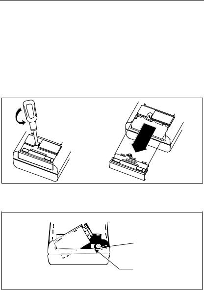
3.Turn the instrument over and remove screw from battery cover as shown in Figure 2-1.
4.Use your thumbs to push off the battery cover as shown in Figure 2-1.
5.Slide the battery out of the compartment as shown in Figure 2-2.
6.Carefully pull the battery clip free from the battery terminals (if replacing the battery) and attach the new battery.
7.Slide the battery and its leads into the compartment and slide the cover into place.
Use thumbs to push battery cover down and then out from instrument case.
CLOSE |
|
WARNINGSHOCK |
||
TO |
AVOID |
|
|
|
INPUTS |
BEFORE |
REMOVE |
||
|
COVER |
|
||
|
|
|
BEFOREOPENING |
|
|
|
|
|
USE |
CLOSE |
|
WARNINGSHOCK |
||
TO |
AVOID |
|
|
|
INPUTS |
BEFORE |
REMOVE |
||
|
COVER |
|
||
|
|
|
BEFOREOPENING |
|
|
|
|
|
USE |
Backside of
8060A
dy03f.eps
Figure 2-1. Removal of Battery Compartment Cover


 Fuse in Circuit
Spare Fuse
dy04f.eps
Figure 2-2. Battery Removal and Fuses
2-4

Operation Instructions 2
Fuse Replacement
You can measure the voltage of your battery by using the following procedure:
1.Select the dc voltage function and the 20V range.
2.Locate the opening for the battery eliminator jack on the right side of the instrument to the right of the display. Touch the red (VΩS) probe tip to
the side contact (not the center pin). Be sure you do not short the battery by shorting the side contact to the center pin. Battery voltage should be between 5.2V to 10V for proper operation. If the voltage is less, the battery should be replaced.
2-4. Fuse Replacement
There are two fuses located at the right side of the battery compartment (refer to Figure 2-2 or examine your instrument). The fuse at the far right is F1. Fuse F1, 2A/250V, protects the current input from an input overload. The other fuse is a spare fuse for F1. When you purchase your instrument, F1 should be installed and the spare fuse should be in one of the two slots next to it. The larger slot is for the American-style fuse, and the smaller slot is for the European-style fuse (either style fuse fits in the installation compartment).
If you need to replace F1, use the tip of a test lead to push the fuse forward from the end and then up to release. Replace F1 with the appropriate 2A/250V fuse; American-style: fast-acting, type AGX2, 1/4 x 1”, Fluke PN 376582; European-style: 5 x20 mm, Fluke PN 460972. Do not use makeshift fuses or short-circuit the fuseholder.
There is another fuse, F2, 3A/600V, which also protects the current input. The instrument cover must be removed to replace F2. This procedure is described in Chapter 4 and should only be done by a person qualified to service the instrument.
The following steps provide a quick and easy way to check the condition of both fuses F1 and F2:
1.Select the resistance function and the 2 kΩ range.
2.Touch the red test lead tip to the A input jack so that the VΩS input and the A input are shorted together.
3.If the display reads .1000 ± .0100 kΩ, both fuses are good.
4.If the display read OL, one or both fuses need replacement.
2-5

8062A
Instruction Manual
2-5. Physical Features
Before you begin using your 8062A, we suggest you take a few minutes to familiarize yourself with the instrument. All of the externally accessible features are shown in Figure 2-3 and described in Table 2-1. The front panel and the display are also described in the following paragraphs.
2-6. Front Panel
The front panel of the 8062A is designed to make function and range selection easy. The symbols and colors on the panel indicate which switches to push or buttons to press to select the function you want. Details are provided later with the description of each function.
12 |
|
|
11 |
|
REL |
1000 |
DC |
M |
AC |
|
|
750 |
|
|
2000mA |
|
200k |
|
200 |
|
|
|
|
200mA |
|
20k |
|
20 |
|
|
|
|
20mA |
|
|
10 |
|
2k |
|
|
2 |
9 
8 
7
2mA |
200 |
|
|
|
|
|
|
|
|
|
|
200mV |
|
|
|
|
|
µA |
|
|
|
|
|
200 |
|
|
|
|
|
DC |
|
|
|
|
|
AC |
|
|
|
S |
|
|
V |
|
|
|
|
A |
|
|
|
|
|
|
|
|
|
S |
|
|
|
|
|
V |
|
|
|
|
|
|
|
|
COMMON |
|
|
||
|
A |
|
|
|
|
|
|
|
|
! |
|
|
|
|
|
DC |
|
|
|
|
|
1000V AC |
|
|
! |
500V |
MAX |
750V |
|
|
|
MAX |
|
||
|
2AMAX |
|
|
|
|
4
6 5
1 
2
 3
3
dy05f.eps
Figure 2-3. Controls, Indicators and Connectors
2-6

|
|
|
|
Operation Instructions |
2 |
|
|
|
|
|
Physical Features |
||
|
|
|
Table 2-1. Controls, Indicators and Connectors |
|
|
|
|
|
Item |
Name |
Function |
|
|
|
|
No. |
|
|
|
|
|
|
1W* |
Battery Eliminator |
External input power connector for use with |
||
|
|
|
Connector |
the A81 Battery Eliminator accessory. |
|
|
|
|
|
|
|
||
|
2 |
Function Buttons: |
Push buttons that toggle on or toggle off the |
|||
|
|
|
, REL |
‘secondary functions: visible or audible |
|
|
|
|
|
|
continuity, or relative. These functions are |
|
|
|
|
|
|
selected in conjunction with the primary |
|
|
|
|
|
|
measurement functions (see items 7 and 8). |
||
|
|
|
|
|
||
|
3 |
Battery |
Cover for the 9V battery and the current fuse |
|||
|
|
|
Compartment and |
F1. |
|
|
|
|
|
Cover |
|
|
|
|
|
|
|
|
|
|
|
4 |
V Ω S Input |
Protected test lead connector used as the |
|
|
|
|
|
|
Connector |
high input for all voltage, resistance, and |
|
|
|
|
|
|
continuity measurements. All test lead |
|
|
|
|
|
|
connectors accept standard or safety- |
|
|
|
|
|
|
designed banana plugs. |
|
|
|
|
|
|
|
|
|
|
5 |
COMMON Input |
Protected test lead connector used as the |
|
|
|
|
|
|
Connector |
low or common input for all measurements. |
||
|
|
|
|
|
|
|
|
6 |
A Input Connector |
Protected test lead connector used as the |
|
|
|
|
|
|
|
high input for current measurements. |
|
|
|
|
|
|
|
|
|
|
7 |
Function |
Interlocked switches that are used in |
|
|
|
|
|
|
Switches: A,V, Ω, |
conduction with the input connectors to |
|
|
|
|
|
|
select the measurement functions. Pushing |
||
|
|
|
|
one switch releases the other, or both may |
|
|
|
|
|
|
be pushed together. |
|
|
|
|
|
|
|
||
|
8 |
AC/DC Function |
Push-on/push-off switch is used to select ac |
|||
|
|
|
Switch |
or dc for current or voltage measurements. |
|
|
|
|
|
|
(Does not affect selection of diode test or |
|
|
|
|
|
|
resistance functions). |
|
|
|
|
|
|
|
||
|
9 |
Range Switches |
Interlocked switches that are used to select |
|||
|
|
|
|
ranges. Pushing a switch selects the |
|
|
|
|
|
|
corresponding range and released other |
|
|
|
|
|
|
switch depressions. Also used to select |
|
|
|
|
|
|
conductance and the diode test. |
|
|
|
|
|
|
|
|
|
* For safe operation, fully insert the A81.
2-7
8062A
Instruction Manual
Table 2-1. Controls, Indicators and Connectors (cont)
Item |
Name |
Function |
|
No. |
|||
|
|
||
|
|
|
|
10 |
Tilt Bail |
A fold-out stand. The bail may also be |
|
|
|
removed (press on one of the legs at the |
|
|
|
hinge of the bail) and reinserted from the top |
|
|
|
as a hook for hanging the instrument. |
|
|
|
|
|
11 |
Power Switch |
Slide switch for turning instrument on or off. |
|
|
|
|
|
12 |
Display |
4½ digit LCD display (19999 maximum) with |
|
|
|
decimal point, minus sign, over-range, |
|
|
|
continuity and relative indicators. |
|
|
|
|
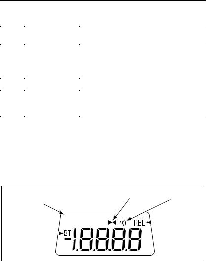
2-7. Display
The 8062A provides measurement results on the 4-1/2 digit LCD display (refer to Figure 2-4 or your instrument). The decimal point is placed automatically. Symbols in the upper portion of the display indicate when one of the secondary functions is enabled. The measurement units are indicated by the range switch that is pushed in. Leading zeroes not displayed.
|
|
|
|
|
|
|
Visible Continuity |
|
Audible |
||
|
|
|
|
|
|
|
Continuity |
||||
Continuity |
|
|
|
|
Enabled |
||||||
Indicator |
|
|
|
|
|
|
|
Enabled |
|||
|
|
|
|
|
|
|
|
|
|
|
Relative |
|
|
|
|
|
|
|
|
|
|
|
|
|
|
|
|
|
|
|
|
|
|
|
|
|
|
|
|
|
|
|
|
|
|
|
|
Low Battery |
|
|
|
|
|
|
|
|
Function |
||
Indicator |
|
|
|
|
|
|
|
|
|
|
in Use |
dy06f.eps
Figure 2-4. 8062A Display
If you are taking a measurement and the OL symbol appears on the display (Figure 2-5), an overrange condition is indicated, meaning that the input is higher than the range selected. You should select a higher range for the measurement. The OL symbol does not necessarily mean that the instrument is being exposed to a damaging input condition. For example, when measuring resistance, an open input will cause OL to appear.
2-8
Loading...