


701
Table of contents
 Loading...
Documenting Process Calibrator
November 1994, Rev. 4, 3/98
© 1994, 1995, 1996, 1998 Fluke Corporation. All rights reserved. Printed in U.S.A.
All product names are trademarks of their respective companies.
Visit the Fluke website at: www.fluke.com
701/702
Users Manual
¨


Table of Contents
Title Page
Introduction........................................................................................................ 1
Standard Equipment ..................................................................................... 4
Safety Information ............................................................................................. 10
Getting Acquainted with Your Calibrator ........................................................... 12
Input and Output Jacks................................................................................. 12
Keys.............................................................................................................. 14
Display .......................................................................................................... 17
Setting Up the Calibrator................................................................................... 17
Using the Strap and Bail ............................................................................... 17
Charging the Battery..................................................................................... 20
Battery Life.................................................................................................... 21
Automatically Saving Battery Life.................................................................. 23
Using the Optional Battery Eliminator ........................................................... 23
i

701/702
Users Manual
Selecting the Display Language .................................................................... 24
Adjusting the Display Contrast....................................................................... 24
Setting Up the Date and Time Display........................................................... 24
Using the Backlight........................................................................................ 25
Personalizing the Calibrator........................................................................... 26
Using Measure Mode......................................................................................... 27
Measurement Ranges.................................................................................... 27
Measuring Electrical Parameters................................................................... 28
Testing Continuity.......................................................................................... 30
Measuring Pressure....................................................................................... 30
Measuring Temperature ................................................................................ 33
Using Thermocouples................................................................................ 33
Using Resistance-Temperature Detectors (RTDs).................................... 36
Measurements in Percent of Scale................................................................ 40
Damping Your Measurements....................................................................... 40
Using Source Mode............................................................................................ 41
Sourcing Electrical Parameters...................................................................... 41
Simulating a 4 to 20 mA Transmitter.............................................................. 43
Providing Loop Power.................................................................................... 45
Sourcing Pressure ......................................................................................... 47
Simulating Thermocouples ............................................................................ 50
Simulating RTDs............................................................................................ 52
Sourcing in Percent of Scale.......................................................................... 54
Stepping and Ramping the Output Value ...................................................... 54
Stepping the Output....................................................................................... 54
ii

Contents
(continued)
Ramping the Output...................................................................................... 55
Simultaneous Measure/Source ......................................................................... 59
Calibrating a Process Instrument ...................................................................... 62
Generating “As Found” Test Data................................................................. 62
Adjusting the Transmitter.............................................................................. 66
“As Left” Test Run......................................................................................... 67
Memory Operations........................................................................................... 68
Saving Results .............................................................................................. 68
Reviewing Memory........................................................................................ 69
Data Logging (Model 702 Only).................................................................... 70
Observing Min and Max Measurements ....................................................... 72
Viewing the Task List (Model 702 Only)........................................................ 72
Clearing Memory........................................................................................... 73
Quick Guide to Applications .............................................................................. 73
Communicating with a PC (Model 702 Only)..................................................... 83
Maintenance...................................................................................................... 83
Replacing the Battery Pack........................................................................... 83
Internal Lithium Backup Battery .................................................................... 83
Cleaning the Calibrator ................................................................................. 83
Calibration Data ............................................................................................ 84
Service Center Calibration or Repair ............................................................ 84
Replacement Parts........................................................................................ 84
Specifications .................................................................................................... 86
DC Voltage Measurement............................................................................. 87
AC Voltage Measurement............................................................................. 88
DC Current Measurement............................................................................. 89
iii

701/702
Users Manual
Resistance Measurement.............................................................................. 89
Continuity Testing.......................................................................................... 90
Frequency Measurement............................................................................... 90
DC Voltage Output......................................................................................... 91
DC Current Output......................................................................................... 92
Resistance Sourcing...................................................................................... 93
Frequency Sourcing....................................................................................... 94
Temperature, Thermocouples ....................................................................... 95
Temperature, Resistance Temperature Detectors ........................................ 98
Loop Power Supply........................................................................................ 99
Top and Bottom Limits of Ranges with Auto Range On ................................ 100
General Specifications................................................................................... 102
Index
iv

List of Tables
Table Title Page
1. Summary of Source and Measure Functions......................................................... 3
2. Input/Output Jacks and Connectors....................................................................... 12
3. Key Functions........................................................................................................ 15
4. Battery Life............................................................................................................. 22
5. Thermocouple Types Accepted............................................................................. 34
6. RTD Types Accepted............................................................................................. 36
7. Simultaneous MEASURE/SOURCE Functions with Loop Power Disabled........... 60
8. Simultaneous MEASURE/SOURCE Functions with Loop Power Enabled............ 61
9. Replacement Parts ................................................................................................ 85
v

701/702
Users Manual
vi

List of Figures
Figure Title Page
1. Standard Equipment.............................................................................................. 5
2. Accessories............................................................................................................ 8
3. Definition of Symbols............................................................................................. 10
4. Input/Output Jacks and Connectors....................................................................... 13
5. Keys....................................................................................................................... 14
6. Elements of a Typical Display................................................................................ 18
7. Installing the Strap and Using the Bail................................................................... 19
8. Removing the Battery and Using the Charger....................................................... 21
9. Electrical Measurement Connections .................................................................... 29
10. Gage and Differential Pressure Modules............................................................... 30
11. Connections for Measuring Pressure..................................................................... 32
12. Measuring Temperature with a Thermocouple...................................................... 35
13. Measuring Temperature with an RTD.................................................................... 39
vii

701/702
Users Manual
14. Electrical Sourcing Connections............................................................................. 42
15. Connections for Simulating a 4 to 20 mA Transmitter............................................ 44
16. Connections for Supplying Loop Power ................................................................. 46
17. Connections for Sourcing Pressure........................................................................ 49
18. Connections for Simulating a Thermocouple.......................................................... 51
19. Connections for Simulating an RTD....................................................................... 53
20. Checking a Relay Output Trip Alarm...................................................................... 58
21. Calibrating a Thermocouple Temperature Transmitter........................................... 63
22. Calibrating a Chart Recorder.................................................................................. 74
23. Measuring Voltage Drop......................................................................................... 74
24. Monitoring AC Line Voltage and Frequency........................................................... 75
25. Calibrating a Current-to-Pressure (I/P) Transducer................................................ 76
26. Measuring the Output Current of a Transmitter...................................................... 77
27. Measuring a Precision Resistor.............................................................................. 78
28. Sourcing Resistance............................................................................................... 78
29. Checking a Switch.................................................................................................. 79
30. Checking a Tachometer ......................................................................................... 79
31. Calibrating a Pressure-to-Current (P/I) Transducer................................................ 80
32. Calibrating a mV to Current Transmitter................................................................. 81
33. Checking a Vortex Shedding Flowmeter ................................................................ 82
34. Operting Environment Specification ....................................................................... 103
viii

Documenting Process Calibrator
Introduction
Fluke 701 and 702 Documenting Process Calibrators
(hereafter referred to as the calibrator) are batterypowered, hand-held instruments that measure and
source electrical and physical parameters. See Table
1. The calibrator lets you troubleshoot, calibrate,
verify, and document the calibration of process
instruments. See the back of this manual for
complete specifications.
In addition to the functions in Table 1, the 701 and
702 calibrators have the following features:
• General features:
Analog display in measurement mode to make it
easy to read the input level when the input is
unstable.
Display shows information in English, French,
German, Italian, or Spanish.
Thermocouple (TC) input/output jack that is
connected to an internal isothermal block with
automatic reference-junction temperature
compensation. Or, you can manually enter an
external temperature reference.
Stores results for later review.
Logs up to 8,000 data points (Model 702 with
PMLink software only.)
PC interface for uploading/downloading
procedures, lists, and results using PMLink
software (Model 702 only).
Automatic calibration procedures for transmitters
using split screen MEASURE/SOURCE mode.
Once you select the test parameters, you can
select an automatic procedure or you can
execute the test points one at a time.
• Features available in MEASURE mode:
1

701/702
Users Manual
Damping (smoothing of the last several
readings).
Display of measurements in engineering units or
percent of scale.
Data logging (Model 702 only).
• Features available in SOURCE mode:
An output ramp feature for testing limit switches.
Trip detect is either a 1V change or a continuity
status change (Open or Short) from one ramp
increment to the next.
An output step feature in which you set the step
size and press
uor dto step the output in
engineering units or percent of scale.
Unless stated otherwise, everything in this
manual applies to both the Fluke 701 and 702
Documenting Process Calibrators. For
maintenance, repair, performance testing, and
calibration instructions, order the 701/702
Service Manual (PN 944525). The phone
number in the USA and Canada for replacement
parts is: 1-800-526-4731. For service help in the
USA and Canada call 1-800-825-9810. For
application or operation assistance on Fluke
products call:
800-44-FLUKE (800-443-5853) in USA and
Canada
(31 40) 644200 in Europe
(206) 356-5500 from other countries
2
Documenting Process Calibrator
Introduction
Table 1. Summary of Source and Measure Functions
FUNCTION MEASURE SOURCE
v dc V 0 to ±300V 0 to 11V in V or mV units (10 mA max)
h ac V 0 to 300V rms, 20 Hz to 5 kHz No sourcing
h Frequency 1 Hz to 50 kHz, 110 mV to 300V rms 1 mV to 10V pk square wave, 2 Hz to 50 kHz
q Resistance 0Ω to 11 kΩ 0Ω to 11 kΩ
m dc Current 0 to 110 mA 0 to 22 mA (28V max)
q Continuity Beep and the word Short indicates
continuity
t Thermocouple E, N, J, L, K, T, U, B, R, S, or C
t RTD
Measure 2,3, or 4 wire.
Source 2 Wire.
p Pressure 14 modules ranging from 0 to 10” H20
(2.5 kPa) to 0 to 10,000 psi (69,000
kPa)
s Loop Power 24 or 28V (22 mA max)
Note: Use an external hand pump or other pressure source as a pressure stimulus for the source pressure function.
No sourcing
100Ω Platinum (3926)
100Ω Platinum (385)
120Ω Nickel (672)
200Ω Platinum (385)
500Ω Platinum (385)
1000Ω Platinum (385)
10Ω Copper (427)
100Ω Platinum (3916)
Note
3

701/702
Users Manual
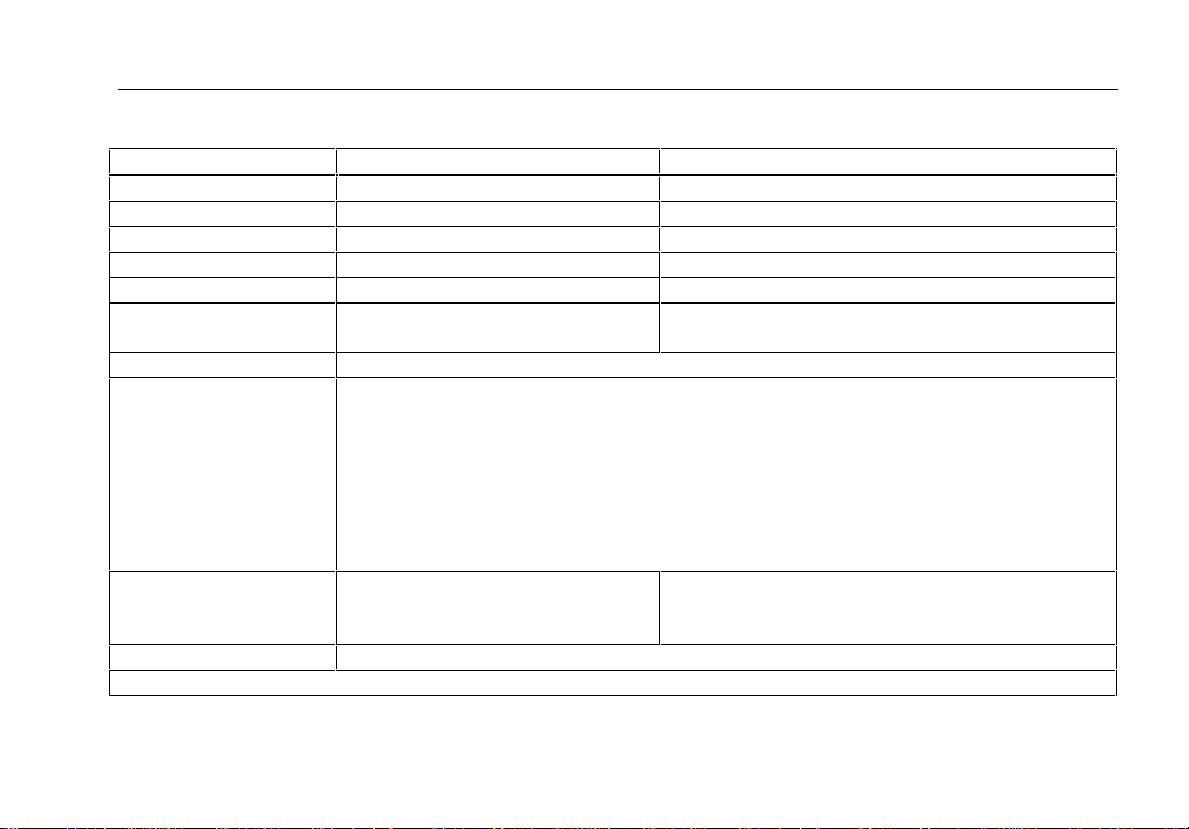
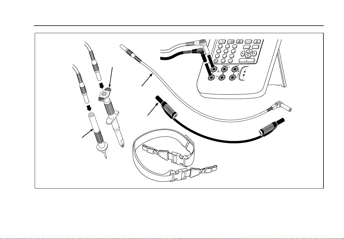
Standard Equipment
The items listed below and shown in Figure 1 are
included with your calibrator. If the calibrator is
damaged or something is missing, contact the place
of purchase immediately. To order replacement parts
or spares, see the user-replaceable parts list at the
end of this manual.
• TL24 industrial test leads (two sets).
• AC20 test clips (two sets).
• TP20 test probes (one set).
• Model BP7217 rechargeable nickel-cadmium
battery pack.
• Model BC7210 battery charger.
• Adjustable quick-release strap.
• Jumper for three-wire RTD measurement
connections (two included).
• 701/702 Users Manual.
• 701/702 Quick Reference Guide.
• Registration card.
4
Documenting Process Calibrator
Introduction
TP20
Test Probe
AC20
Test Clip
TL24
Test Leads
(2 Red and 2 Black)
Jumper
Figure 1. Standard Equipment
Strap
123
V
RTD
30V MAX
V
V
Hz
7
89
456
0
.
mA mA
RTD
MEASSOURCE
TC
RTD
CLEAR
RANGE
(ZERO)
ENTER
V
300V
TC
MAX
5
701/702
Users Manual
Users
Manual
Quick
Reference
Guide
Mail-in
Card
BC7210
Battery Charger
or
Figure 1. Standard Equipment (cont)
7.2V
1700 mAh
Ni-Cd
U.S.A.
CORPORATION
FLUKE
Nickel-Cadmium
Battery Pack
DO NOT EXPOSE TO FIRE
SPECIFIED IN MANUAL
USE CHARGING PROCEDURES
OF PROPERLY
MUST BE RECYCLED OR DISPOSED
DISASSEMBLE
DO NOT SHORT CIRCUIT OR
USE ONLY WITH FLUKE PRODUCTS
SAFE OPERATION
REFER TO USERS MANUAL FOR
RECHARGEABLE BATTERY
NICKEL-CADMIUM
BP7217
BP7217
6

Documenting Process Calibrator
Introduction
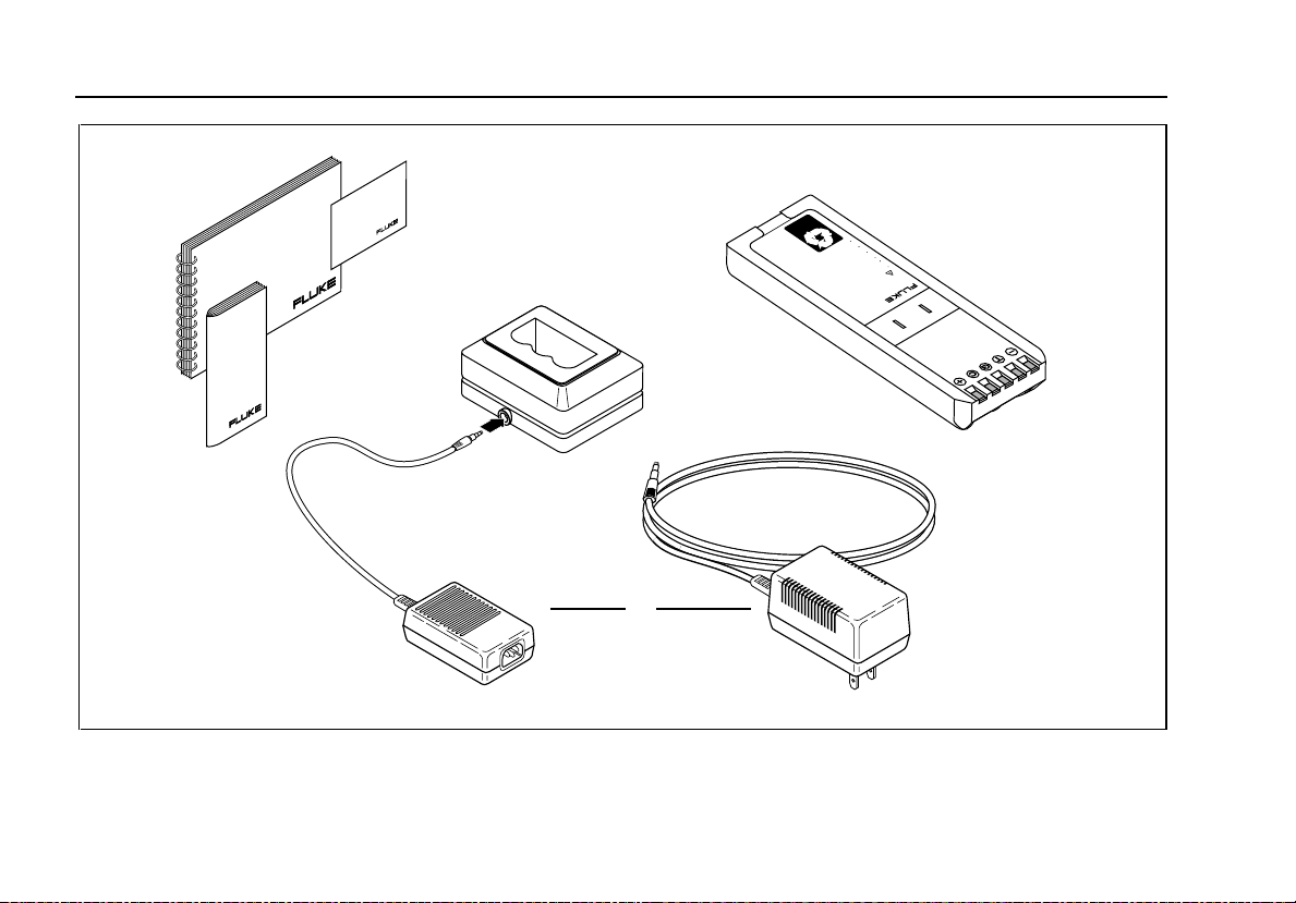
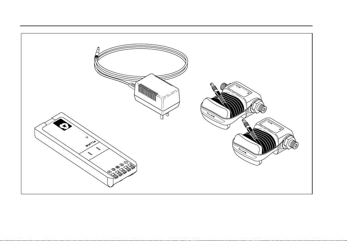
The accessories listed below and shown in Figure 2
are available from Fluke:
• Pressure Modules, Fluke model numbers listed
below. (Differential models also operate in gage
mode.)
700P01: 0 to 10 inches of H
O, or 2.5 kPa
2
(differential nonisolated)
700P02: 0 to 1 psi (differential, nonisolated)
700P03: 0 to 5 psi (differential, nonisolated)
700P04: 0 to 15 psi (differential, nonisolated)
700P22: 0 to 1 psi (differential, isolated)
700P23: 0 to 5 psi (differential, isolated)
700P24: 0 to 15 psi (differential, isolated)
700P05: 0 to 30 psi (gage, isolated)
700P06: 0 to 100 psi (gage, isolated)
700P07: 0 to 500 psi (gage, isolated)
700P08: 0 to 1000 psi (gage, isolated)
700P29: 0 to 3000 psi (gage, isolated)
700P30: 0 to 5000 psi (gage, isolated)
700P31: 0 to 10000 psi (gage, isolated)
• Model BE9005 Series Battery Eliminator for
bench-top use.
• PMLink software and cable for developing
procedures and transferring procedures and
data (for Model 702 only).
• Model BP7217 Nickel-Cadmium battery pack.
• Service Kit.
• C700 Carrying Case.
7
701/702
Users Manual
7.2V
U.S.A.
1700 mAh
Ni-Cd
CORPORATION
FLUKE
DO NOT EXPOSE TO FIRE
SPECIFIED IN MANUAL
USE CHARGING PROCEDURES
OF PROPERLY
MUST BE RECYCLED OR DISPOSED
DISASSEMBLE
DO NOT SHORT CIRCUIT OR
USE ONLY WITH FLUKE PRODUCTS
SAFE OPERATION
REFER TO USERS MANUAL FOR
RECHARGEABLE BATTERY
NICKEL-CADMIUM
BP7217
BE9005
Battery
Eliminator
BP7217
Nickel-Cadmium
Battery Pack
RANGE
700
PRESSURE MODULE
15 PSID/G
Fluke-700P0X
Gage Pressure Module
Fluke-700P0X
Differential
Pressure Module
P
04
1 bar100 kPa
RANGE
700
PRESSURE MODULE
P
100 PSIG
7 bar700 kPa
06
Figure 2. Accessories
8
PMLink
Manual
Documenting Process Calibrator
Introduction
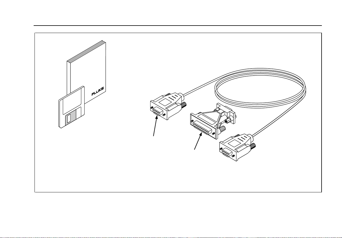
PMLink Software
3.5-Inch Floppy Disk
PMLink Software
RS-232 Cable
DB9 to DB25
(9-Pin to 25-Pin)
Adapter
Figure 2. Accessories (cont)
9
701/702
Users Manual
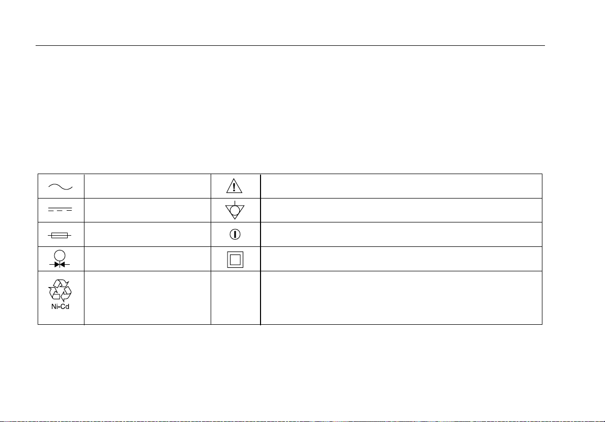
Safety Information
wThis calibrator is designed and tested in
accordance with IEC1010-1 and CAN/CSA C22.2
No. 1010.1-92. Use the calibrator only as specified in
this manual or in the Quick Reference Guide;
otherwise the protection provided by the calibrator
may be impaired.
AC-Alternating Current
DC-Direct Current
Fuse
Pressure
Recycling
CAT
II
Figure 3. Definition of Symbols
A WARNING identifies conditions and actions that
pose hazards to the user; a CAUTION identifies
conditions and actions that may damage the
calibrator or the equipment under test.
Symbols used on the calibrator and in this manual
are explained in Figure 3.
CAUTION see explanation in manual
Common (LO) Input equipotentiality
ON/OFF
Equipment protected throughout by DOUBLE INSULATION or
REINFORCED INSULATION
II
Overvoltage (Installation) Category
of Impluse Withstand Voltage protection provided. Typical locations
include; Mains Wall outlets, local appliances and PORTABLE
EQUIPMENT.
per IEC 1010-1 refers to the level
10

Documenting Process Calibrator
Safety Information
To protect yourself, follow these safety guidelines:
• Do not use the calibrator if it is damaged. Before
you use the calibrator, inspect the insulating
cover. Look for cracks or missing plastic. Pay
particular attention to the insulation surrounding
the connectors.
• Disconnect the power and discharge all high-
voltage capacitors in the equipment under test
before testing resistance or continuity.
• Inspect the test leads for damaged insulation or
exposed metal. Check test lead continuity.
Replace damaged test leads before using the
calibrator.
• Do not use the calibrator if it operates
abnormally. Protection may be impaired. When
in doubt, have the calibrator serviced.
• Select the proper function and range for your
measurement.
• Use caution when working above 42V pk, 30V
ac rms, or 60V dc. Such voltages pose a shock
hazard.
• When using the probes, keep your fingers away
from the probe contacts. Keep your fingers
behind the finger guards on the probes.
• Connect the common test lead before you
connect the live test lead. When you disconnect
test leads, disconnect the live test lead first.
• Do not operate the calibrator around explosive
gas, vapor, or dust.
• When using a pressure module, make sure the
process pressure line is shut off and
depressurized before you connect it to the
pressure module.
• Disconnect test leads before changing to
another measure or source function.
• When servicing the calibrator, use only specified
replacement parts.
11

701/702
Users Manual
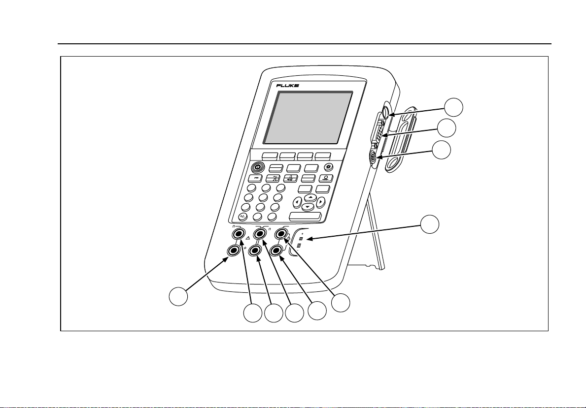
Getting Acquainted with Your Calibrator
Input and Output Jacks
Figure 4 shows the calibrator input and output jacks.
Table 2 explains their use.
Table 2. Input/Output Jacks and Connectors
ITEM FEATURE DESCRIPTION
1 Battery Eliminator jack Jack for the Model BE9005 Battery Eliminator. Use the battery eliminator for bench-
top applications where ac line power is available. This input does not charge the
battery. The battery can only be charged in the external charger.
2 wSERIAL PORT (702
Only)
3 Pressure module
connector
4 TC input/output Jack for measuring or simulating thermocouples. This jack accepts a miniature
5, 6 w MEAS V jacks Input jacks for measuring voltage, frequency, or three- or four-wire RTDs (Resistance
7, 8 w SOURCE mA,
MEAS mA Ω RTD
jacks
9,10 w SOURCE V Ω RTD
jacks
Connects the calibrator to a personal computer. Instructions for communicating with the
calibrator are in the PMLink Software manual.
Connects the calibrator to a pressure module.
polarized thermocouple plug with flat, in-line blades spaced 7.9 mm (0.312 in) center to
center.
Temperature Detectors).
Jacks for sourcing or measur ing current, measuring resistance and RTDs, and
supplying loop power.
Output jacks for sourcing voltage, resistance, frequency, and for simulating RTDs
12
123
V
RTD
30V MAX
MEAS
SOURCE
V
V
Hz
7
89
456
0
.
mA mA
RTD
300V
MEASSOURCE
MAX
702
702
mA
SETUP
TC
RTD
CLEAR
(ZERO)
ENTER
V
TC
DOCUMENTING PROCESS CALIBRATOR
DOCUMENTING PROCESS CALIBRATOR
RANGE
Documenting Process Calibrator
Getting Acquainted with Your Calibrator
1
2
3
4
10
5
9
8
6
7
Figure 4. Input/Output Jacks and Connectors
13
701/702
Users Manual
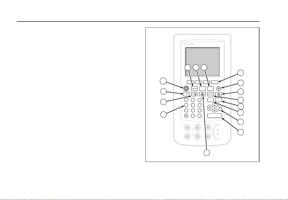
Keys
Figure 5 shows the calibrator keys and Table 3
explains their functions. The softkeys are the four
unmarked blue keys just below the display. Softkey
functions are defined by the labels that appear above
the softkey during operation. Softkey labels and
other display text are shown in this manual in bold
type, for example, Choices.
DOCUMENTING PROCESS CALIBRATOR
702
21
3
4
16
MEAS
15
14
13
SOURCE
V
V
Hz
789
456
123
0
V
mA mA
RTD
30V MAX
SETUPmA
TC
RTD
CLEAR
RANGE
(ZERO)
ENTER
.
V
RTD
300V
MEASSOURCE
TC
MAX
5
6
7
8
9
10
11
12
Figure 5. Keys
14

Documenting Process Calibrator
Getting Acquainted with Your Calibrator
Table 3. Key Functions
ITEM FEATURE DESCRIPTION
1 M key Cycles the calibrator through MEASURE, SOURCE, and MEASURE/SOURCE
modes.
2 m key Selects mA (current) measure or source function. For loop power on/off, go to the
s mode.
3 s key Enters and exits the s mode to modify operating parameters.
4 Softkeys Perform the function defined by the label above each key on the display.
5 C key Turns the backlight on and off.
6 p key Selects the pressure measurement or sourcing function.
7 t key Selects TC (thermo couple) or RTD (resistance temperature detector) measurement
or sourcing functions.
8 r key Toggles between autorange and locked range, and increments range. Each time
you press r, the calibrator locks on the next range. Press this key again for 2
seconds to resume autorange.
9 c key Clears a partial data entry, or zeros the output when in the SOURCE mode.
10 u, d, L, R keys Adjust the display contrast. Also, use these keys to make selections when
prompted. These keys also increase or decrease the output in SOURCE mode
when using the step feature.
15

701/702
Users Manual
Table 3. Key Functions (cont)
ITEM FEATURE DESCRIPTION
11 e key Terminates a numeric entry when setting a source value, or selects entries from lists.
12 q key Toggles between resistance and continuity functions in MEASURE mode, or selects
the resistance function in SOURCE mode.
13 Numeric keypad Used whenever a numeric entry is required.
14 h key Toggles between ac voltage and frequency functions in MEASURE mode, or selects
frequency output in SOURCE mode.
15 v key Selects the dc voltage function in MEASURE mode, or selects dc voltage in SOURCE
mode.
16 o key Turns the power on and off.
16

Documenting Process Calibrator
Setting Up the Calibrator
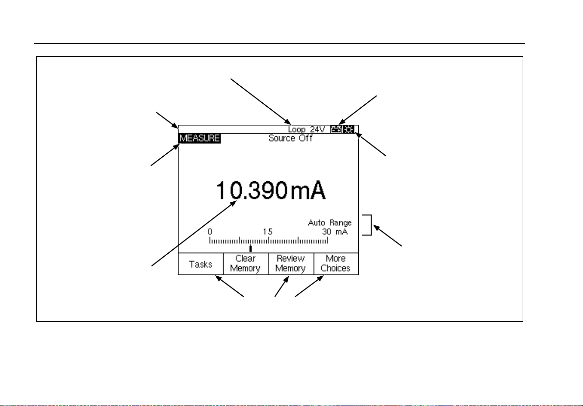
Display
Figure 6 shows the features of a typical display. The
display shown is MEASURE mode. Near the top of
the display is “Source Off.” This is the area of the
display that shows what is happening in the other
mode (SOURCE or MEASURE). The other parts of
the display are as follows:
Status Bar: shows the time and date (if set in
•
Setup mode), and shows the status of Loop
Power, Battery Save, and Backlight Timeout; all
of which are set in Setup mode. The low battery
and backlight on annunciators also appear here.
Mode Indicator: Shows whether the calibrator is
•
in MEASURE or SOURCE mode. In split screen
MEASURE/SOURCE mode, there is a Mode
Indicator for each window.
Measured Value: Shows the measured value in
•
your choice of engineering units or percent of
scale.
Range Status: Shows whether Auto Range is on,
•
and what range is currently being used.
Setting Up the Calibrator
This section consists of general information that
should be read before you use the calibrator.
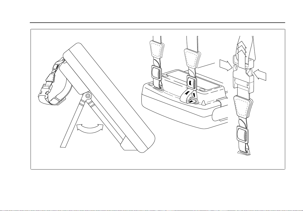
Using the Strap and Bail
After you unpack the calibrator, attach its carrying
strap as shown in Figure 7. You can adjust the strap
as necessary to hang the calibrator on any sturdy
support. Figure 4 also shows you how to prop open
the bail to stand the calibrator at a comfortable
viewing angle for benchtop use.
17
701/702
Users Manual
Status Bar
Mode Indicator
Measured Value
Loop Power Annunciator
Battery Save Annunciator
Backlight Timeout
Annunciator
Range Status
Softkey Labels
18
Figure 6. Elements of a Typical Display
Documenting Process Calibrator
Setting Up the Calibrator
Figure 7. Installing the Strap and Using the Bail
19

701/702
Users Manual
Charging the Battery
wBefore you use the calibrator for the first time,
charge its battery pack for 2 hours. Due to safety
requirements, the battery must be charged outside
the calibrator.
Figure 8 shows how to remove the battery. Remove
the battery door and tap the calibrator with your hand
to get the battery out. Place the battery in the
charger and connect the charger to line power. The
charger automatically senses line voltage and
adjusts itself accordingly.
A discharged battery is fully charged in 2 hours or
less in fast-charge mode (steady indicator light on
the charger). Full charge is maintained after that time
in trickle-charge mode (blinking indicator light on the
charger). Switching between charging modes is
automatic. You can leave the battery pack on trickle
charge indefinitely without damage.
NOTE
When you remove a charged battery from
the charger, wait for the blinking indicator to
go off before you insert a discharged battery.
It takes about 2 seconds for the battery
charger to reset.
20
Loading...