

Page 1
USER INSTRUCTIONS
Flowserve KW941
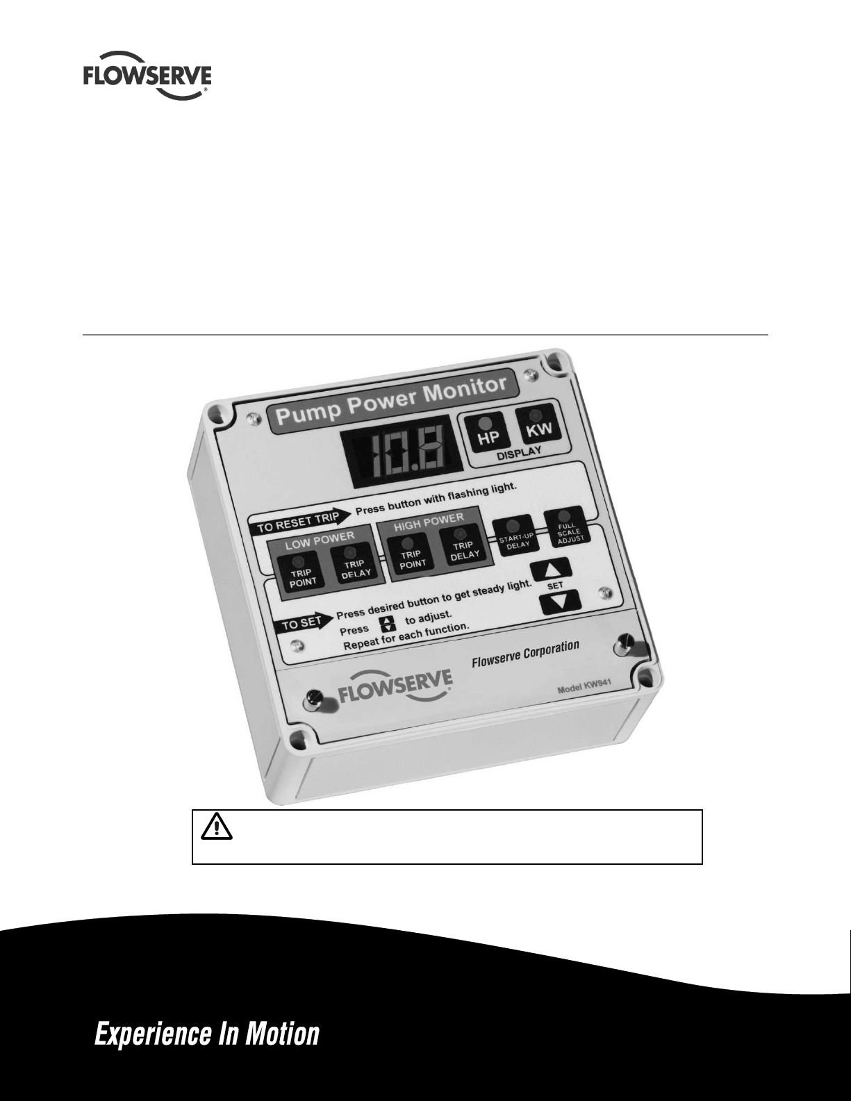
Pump Power Monitor™
Pump Power Monitor for protection against both under load and
over load conditions.
PCN= = 71569285 – 02-12 (E) (incorporates PM-200 & PM-201)
Original instructions.
Installation
Operation
Maintenance
These instructions must be read prior to installing,
operating, using and maintaining this equipment.
Page 2

KW941 Pump Power Monitor USER INSTRUCTIONS ENGLISH 71569285 02-12
CONTENTS
Page
1 INTRODUCTION AND SAFETY ............................ 3
1.1 General ........................................................... 3
1.2 CE marking and approvals .............................. 3
1.3 Disclaimer ....................................................... 3
1.4 Copyright ......................................................... 3
1.5 Duty conditions ................................................ 3
1.6 Safety .............................................................. 4
1.7 Nameplate and safety labels ........................... 5
1.8 Specific machine performance ........................ 5
2 TRANSPORT AND STORAGE .............................. 5
2.1 Consignment receipt and unpacking............... 5
2.2 Handling .......................................................... 5
2.3 Storage ............................................................ 5
2.4 Recycling and end of product life .................... 5
3 DESCRIPTION ...................................................... 6
3.1 Configurations ................................................. 6
3.2 Nomenclature .................................................. 6
3.3 Design of major parts ...................................... 6
3.4 Performance and operation limits ................... 7
4 INSTALLATION ...................................................... 8
4.1 Location ........................................................... 8
4.2 Electrical connections ..................................... 8
5 SETUP AND OPERATION .................................. 13
5.1 Display Mode – Power Units Selection ......... 13
5.2 Full Scale Adjust ............................................ 13
5.3 Alarms ........................................................... 14
5.4 Demo Mode ................................................... 16
5.5 Current Sensor Field Replacement ............... 16
6 MAINTENANCE ................................................... 17
6.1 Spare parts .................................................... 17
6.2 Tools required ................................................ 17
7 FAULTS: CAUSES AND REMEDIES .................. 17
8 PARTS LIST AND DRAWINGS ........................... 20
9 CERTIFICATION ................................................. 23
10 OTHER RELEVANT DOCUMENTATION AND
MANUALS ........................................................ 23
10.1 Supplementary user instructions .................. 23
10.2 Change Notes .............................................. 23
Page 2 of 24 flowserve.com
Page 3

KW941 Pump Power Monitor USER INSTRUCTIONS ENGLISH 71569285 02-12
1 INTRODUCTION AND SAFETY
1.1 General
These instructions must always be kept
close to the product's operating location or
directly with the product.
Flowserve products are designed, developed and
manufactured with state-of-the-art technologies in
modern facilities. The unit is produced with great
care and commitment to continuous quality control,
utilizing sophisticated quality techniques and safety
requirements.
Flowserve is committed to continuous quality
improvement and being at service for any further
information about the product in its installation and
operation or about its support products, repair and
diagnostic services.
These instructions are intended to facilitate
familiarization with the product and its permitted use.
Operating the product in compliance with these
instructions is important to help ensure reliability in
service and avoid risks. The instructions may not
take into account local regulations; ensure such
regulations are observed by all, including those
installing the product. Always coordinate repair
activity with operations personnel, and follow all plant
safety requirements and applicable safety and health
laws and regulations.
These instructions must be read prior to
installing, operating, using and maintaining the
equipment in any region worldwide. The
equipment must not be put into service until all
the conditions relating to safety, noted in the
instructions, have been met. Failure to follow and
apply the present user instructions is considered
to be misuse. Personal injury, product damage,
delay or failure caused by misuse are not covered
by the Flowserve warranty.
1.2 CE marking and approvals
It is a legal requirement that machinery and equipment
put into service within certain regions of the world shall
conform with the applicable CE Marking Directives
covering Machinery and, where applicable, Low Voltage
Equipment, Electromagnetic Compatibility (EMC),
Pressure Equipment Directive (PED) and Equipment for
Potentially Explosive Atmospheres (ATEX).
Where applicable, the Directives and any additional
Approvals, cover important safety aspects relating to
machinery and equipment and the satisfactory provision
of technical documents and safety instructions. Where
applicable this document incorporates information
relevant to these Directives and Approvals.
To confirm the Approvals applying and if the product is
CE marked, check the product identification label and
the Certification. (See section 9, Certification.)
1.3 Disclaimer
Information in these User Instructions is believed to
be complete and reliable. However, in spite of all of
the efforts of Flowserve Corporation to provide
comprehensive instructions, good engineering and
safety practice should always be used.
Flowserve manufactures products to exacting
International Quality Management System Standards
as certified and audited by external Quality
Assurance organizations. Genuine parts and
accessories have been designed, tested and
incorporated into the products to help ensure their
continued product quality and performance in use.
As Flowserve cannot test parts and accessories
sourced from other vendors the incorrect
incorporation of such parts and accessories may
adversely affect the performance and safety features
of the products. The failure to properly select, install
or use authorized Flowserve parts and accessories is
considered to be misuse. Damage or failure caused
by misuse is not covered by the Flowserve warranty.
In addition, any modification of Flowserve products or
removal of original components may impair the safety
of these products in their use.
1.4 Copyright
All rights reserved. No part of these instructions may
be reproduced, stored in a retrieval system or
transmitted in any form or by any means without prior
permission of Flowserve.
1.5 Duty conditions
This product has been selected to meet the
specifications of your purchase order. The
acknowledgement of these conditions has been sent
separately to the Purchaser. A copy should be kept
with these instructions.
The product must not be operated beyond
the parameters specified for the application.
If there is any doubt as to the suitability of the
product for the application intended, contact
Flowserve for advice, quoting the part number.
Page 3 of 24 flowserve.com
Page 4
KW941 Pump Power Monitor USER INSTRUCTIONS ENGLISH 71569285 02-12
If the conditions of service on your purchase order are
going to be changed (for example supply voltage or
frequency) it is requested that the user seeks the
written agreement of Flowserve before start up.
1.6 Safety
1.6.1 Summary of safety markings
These User Instructions contain specific safety
markings where non-observance of an instruction would
cause hazards. The specific safety markings are:
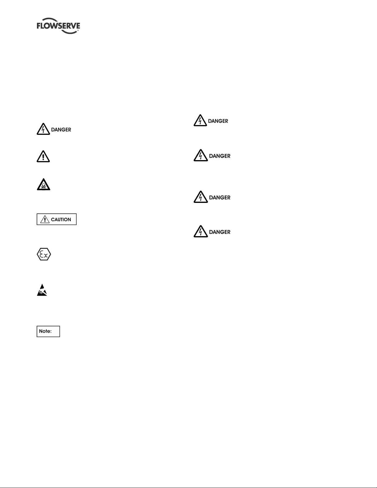
This symbol indicates electrical safety
instructions where non-compliance will involve a high
risk to personal safety or the loss of life.
This symbol indicates safety instructions where
non-compliance would affect personal safety and could
result in loss of life.
This symbol indicates “hazardous and toxic
substances” safety instructions where non-compliance
would affect personal safety and could result in loss of
life.
This symbol indicates safety instructions
where non-compliance will involve some risk to safe
operation and personal safety and would damage the
equipment or property.
This symbol indicates explosive atmosphere zone
marking according to ATEX. It is used in safety
instructions where non-compliance in the hazardous
area would cause the risk of an explosion.
This symbol is used in safety instructions to
remind not to rub non-metallic surfaces with a dry
cloth; ensure the cloth is damp. It is used in safety
instructions where non-compliance in the hazardous
area would cause the risk of an explosion.
Always coordinate repair activity with operations and
health and safety personnel, and follow all plant
safety requirements and applicable safety and health
laws and regulations.
1.6.3 Safety action
This is a summary of conditions and actions to help
prevent injury to personnel and damage to the
environment and to equipment.
NEVER DO MAINTENANCE WORK
WHEN THE UNIT IS CONNECTED TO POWER.
LOCK OUT THE POWER SUPPLY.
Dangerous voltages are present in
motor control panels and circuits. INSTALLATION
MUST BE PERFORMED BY QUALIFIED
PERSONNEL!
Improper installation or operation can
cause damage to the unit and can result in an
unprotected pump or nuisance tripping of the pump.
The current transformer/toroid
secondary leads must always be shorted together or
connected to an appropriate measuring device to
provide a suitable burden whenever the primary
circuit is energized. Operation of a current
transformer/toroid with an open secondary will result
in hazardous voltages and destruction of the device!
This sign is not a safety symbol but indicates
an important instruction in the assembly process.
1.6.2 Personnel qualification and training
All personnel involved in the operation, installation,
inspection and maintenance of the unit must be
qualified to carry out the work involved. If the personnel
in question do not already possess the necessary
knowledge and skill, appropriate training and instruction
must be provided. If required the operator may contact
the manufacturer/supplier to provide applicable
training/technical support.
Page 4 of 24 flowserve.com
Page 5
KW941 Pump Power Monitor USER INSTRUCTIONS ENGLISH 71569285 02-12
1.7 Nameplate and safety labels
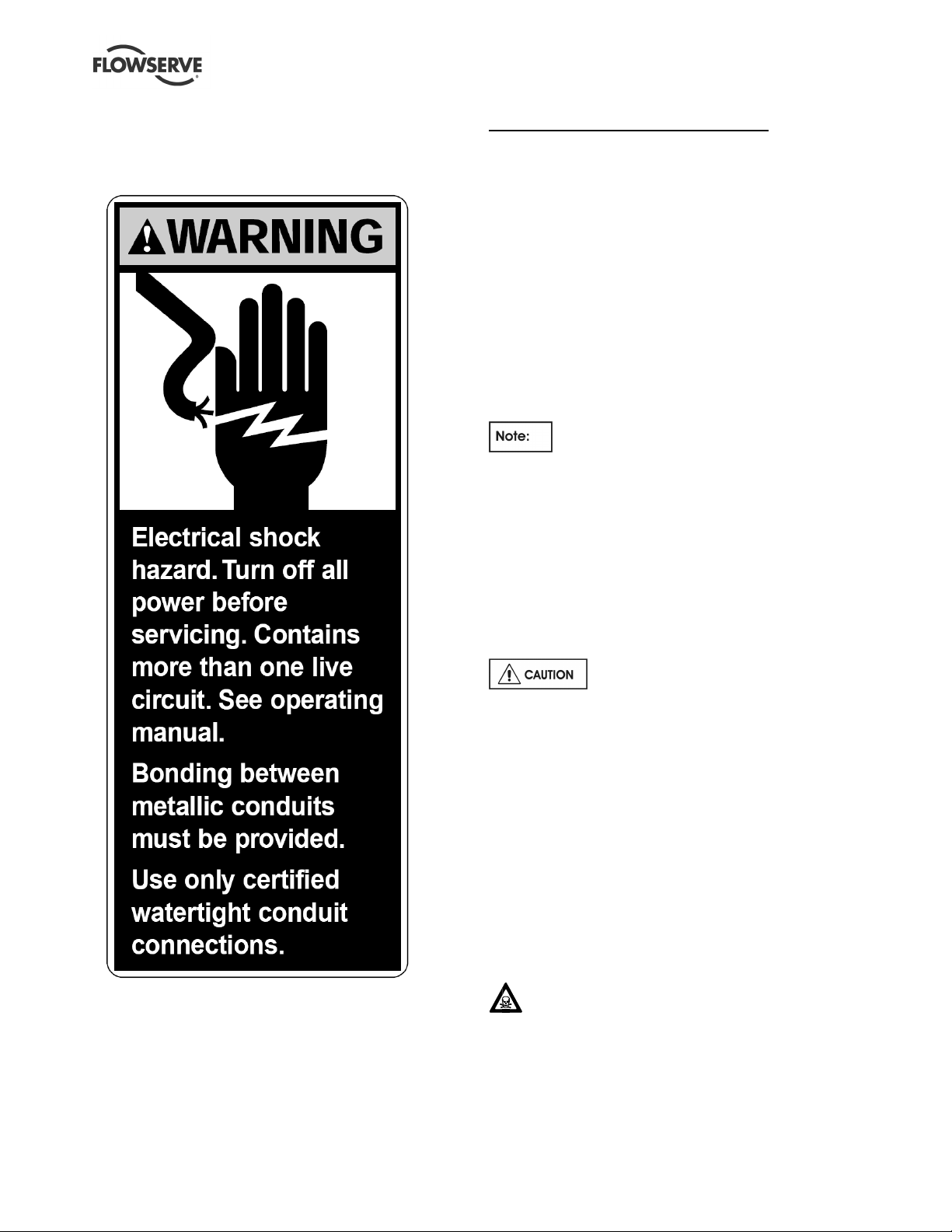
1.7.1 Safety labels
2 TRANSPORT AND STORAGE
2.1 Consignment receipt and unpacking
Immediately after receipt of the equipment it must be
checked against the delivery/shipping documents for
its completeness and that there has been no damage
in transportation. Any shortage and/or damage must
be reported immediately to Flowserve Pump Division
and must be received in writing within ten days of
receipt of the equipment. Later claims cannot be
accepted.
Check all crates, boxes or wrappings for any
accessories or spare parts that may be packed
separately from the equipment or attached to side
walls of the box or equipment.
The current senor (toroid) is shipped inside
the KW941 underneath the wiring compartment
cover.
2.2 Handling
The KW941 Power Monitor is small and light so
handling and mounting are easy. The unit weighs
approximately 2.3 kg (5 lbs).
2.3 Storage
1.8 Specific machine performance
For performance parameters see section 1.5, Duty
conditions. Where performance data has been supplied
separately to the purchaser these should be obtained
and retained with these User Instructions.
Store the pump in a clean, dry location
away from vibration. If kept in its original packaging
and protected from excessive environmental effects
like continuous high humidity or corrosive gases the
shelf life would be decades.
2.4 Recycling and end of product life
At the end of the service life of the product or its
parts, the relevant materials and parts should be
recycled or disposed of using an environmentally
acceptable method and in accordance with local
regulations. If the product contains substances that
are harmful to the environment, these should be
removed and disposed of in accordance with current
local regulations. This also includes the liquids
and/or gases that may be used in the "seal system"
or other utilities.
Make sure that hazardous substances are
disposed of safely and that the correct personal
protective equipment is used. The safety
specifications must be in accordance with the current
local regulations at all times.
Page 5 of 24 flowserve.com
Page 6
KW941 Pump Power Monitor USER INSTRUCTIONS ENGLISH 71569285 02-12
3 DESCRIPTION
3.1 Configurations
The KW941 Pump Power Monitor provides a power
measurement, display and trip-point system to detect
and protect against both UNDERLOAD and
OVERLOAD conditions. The KW941 monitors
MOTOR POWER by sensing both VOLTAGE and
CURRENT. By factoring in motor efficiency, the
KW941 can be scaled to display PUMP POWER. The
adjustable trip-points can be set using power
information provided by the Flowserve Pros+
software for Flowserve pumps.
The KW941 consists of a current sensor and a
Display/Control module. The sensor, through which
one motor power lead passes, normally is located
inside the motor starter panel and provides a sample
of motor current to the Display/Control module. A
voltage sample is provided by a control voltage
transformer (not supplied) located between two of the
three motor power phases. The Display/ Control
module (located outside the starter panel) processes
the current and voltage sample information, contains
the LED display, alarm relays, and provides operator
interface.
Three models of the KW941 Power Monitor are
available based upon the supply voltage at the
customer’s site. The part numbers are listed below:
AY56930B = 110-120v, 60Hz
AY56930C = 220-240v, 50Hz
AY56930D = 220-240v, 60Hz
3.2 Nomenclature
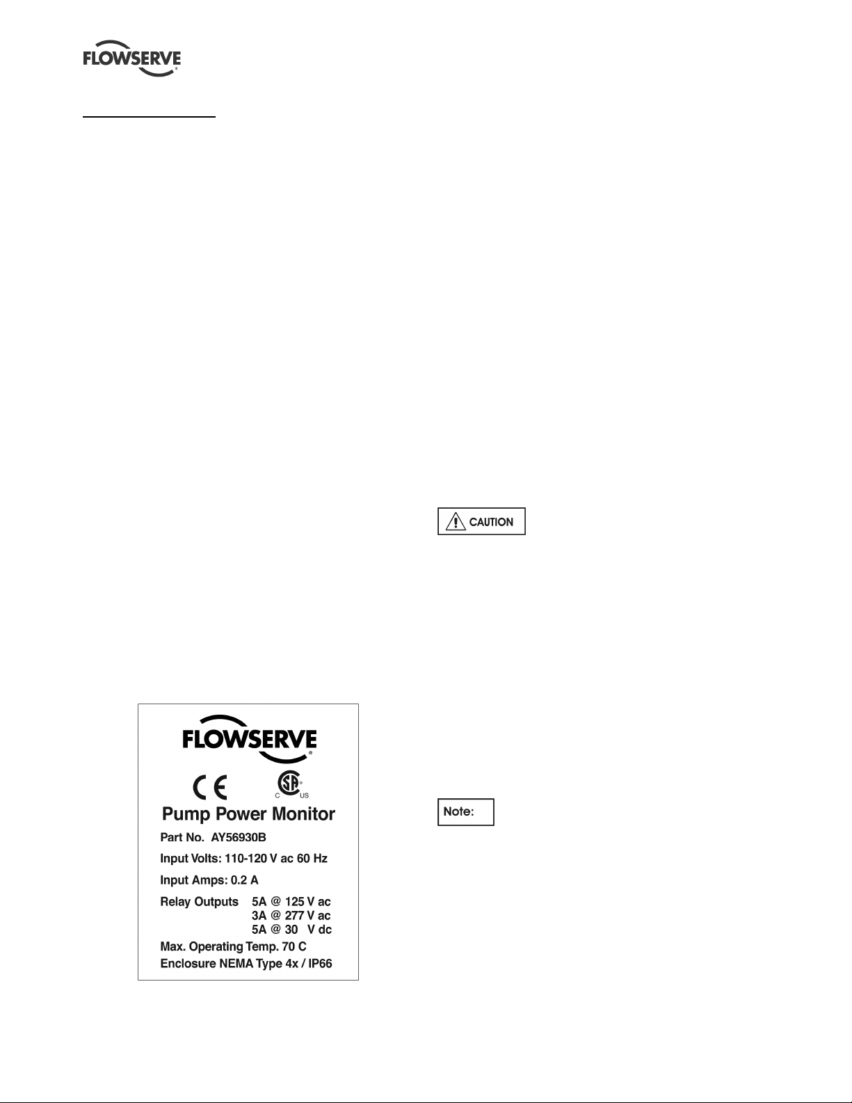
3.2.1 Product Identification Label
3.2.2 Abbreviations
TS = terminal strip
TS1 = terminal strip screw position #1
Jp = jumper
NO = normally open
NC = normally closed
FS = full scale (power)
CR = control relay
MOL = motor overload
3.3 Design of major parts
3.3.1 Enclosure
• Material: polycarbonate, with see-through cover.
• Protection rating: NEMA 4X / IP66. Use only
certified liquid-tight access hole fittings/conduit
hubs to maintain enclosure protection rating.
• Overall dimensions: 182 mm W x 180 mm L x 90
mm H (7.17"W x 7.09"L x 3.54"H).
• Mounting hole spacing: 167 mm W x 173 mm H
(6.57"W x 6.81"H).
• Mounting screws: 4 mm (#8), quantity of four.
• Enclosure can be drilled, sawed or punched for
wiring access holes.
Do not damage the internal
components of the KW941 unit while making access
holes.
3.3.2 Power Requirements
• 110 Vac Model (110/115/120 nominal Vac),
60 HZ @ 0.100 amps
• 220 Vac Models (220/230/240 nominal Vac),
50/60 HZ @ 0.05 amps
• Fuse: (Internal to TS1 #2 VAC connection, not
user accessible.)
• For 110 Vac Models: 200 mA, 125 Vac, Slo
Blo, 5 x 20 mm
• For 220 Vac Models: 100 mA, 250 Vac, Slo
Blo, 5 x 20 mm
Power to the KW941 is supplied by a
(customer-supplied) control voltage transformer
connected between two of the three motor power
supply phases. Power may be supplied by an
existing appropriately connected transformer with
adequate capacity. Consult area codes/regulations
for transformer fusing and grounding requirements.
Page 6 of 24 flowserve.com
Page 7
KW941 Pump Power Monitor USER INSTRUCTIONS ENGLISH 71569285 02-12
Fusing of the control voltage transformer primary
and/or secondary circuit supplying power to the
KW941 may be required. Please consult local area
electrical codes/regulations.
• Control Voltage Transformer: (Not Supplied)
Rating: 15 VA (Volt Amps) or greater.
• Power On/Off Switch: (Not Supplied)
No On/Off switch is provided with the
KW941. It is intended to be On (operational)
whenever power is supplied to the motor starter
control circuits, whether or not the motor is running,
so that it can be set up prior to starting the equipment
and provide protection on startup. The transformer
supplying power to the KW941 is normally installed
ahead of the motor starter contactor but after the
starter power disconnect switch, so that power can be
turned off with the disconnect switch. If required, the
control transformer circuit supplying power to the
KW941 can be switched.
3.3.3 Wiring and Grounding
• Maximum TS1 connection wire size: #14 AWG.
• Use wire with adequate insulation and current
carrying capability for the application.
• Terminal TS1 #1 is internally connected to the
KW941's metal chassis. Connect this point to
earth ground.
• Use of metallic conduits will require bonding
between the conduits.
PLEASE FOLLOW ALL AREA
ELECTRICAL CODES/REGULATIONS!
3.3.4 Full Scale Range
• 0.7 to 112 KW (1 to 150 HP) @ 460 Vac, 50/60
Hz three phase power with the supplied current
sensor (toroid).
• Contact Flowserve Engineering for higher power
capabilities (to 999 hp with auxiliary current
sensor) and for special applications.
3.3.5 Current Sensor (also known as a toroid or
current transformer)
• 200 amp (primary), current sensing toroid
• 12" #24 AWG leads
• Max lead extension length = 30.5 m (100 feet).
• O.D: 51 mm (2.0 in.)
• I.D.: 18 mm (0.7in.) – this limits the maximum
wire size that can go through current sensor.
• Ht.: 20 mm (0.8 in.)
3.3.6 Alarm Output Relay Contacts
5 amps @ 125 VAC
3 amps @ 277 VAC
5 amps @ 30 VDC
3.3.7 Analog Output
• 4 to 20 milliamp source, proportional to full
scale.
• Maximum loop load resistance = 600 Ohms.
3.3.8 Digital Display
• 3 digit, 0.6" high, seven segment, red LED.
• Displays 0.0 to 999
3.3.9 Timers
• Start-Up Delay Timer: Adjustable 0 to 999
seconds.
• Trip Delay Timers: Adjustable 0 to 999 seconds.
3.3.10 Remote Reset
• Momentary external mechanical or solid state
switch to conduct < 200 microamps DC between
"RESET +" and "RESET -" terminals.
• Reset input specifications (for use with solid
state logic switch resets)
• For NORMAL operation: +2 to +5 VDC
between reset terminals
• For RESET: -0.3 to +0.8 VDC between reset
terminals (minimum pulse width 20
milliseconds).
3.4 Performance and operation limits
Operating Temperature: -40 to 70 °C (-40 to 158 °F) .
Effective toroid power limit = 112 KW (150 HP)
Power monitoring using only the supplied
current sensor is limited by its 200 amp current limit
and the size of the motor lead that can fit through the
toroid’s internal diameter (18 mm (0.7 in.)).
Use of a second current transformer in series with the
supplied toroid can allow the KW941 to monitor
power levels up to 745 KW (999 HP).
Supply voltage should not exceed 230 Vac at 50 Hz
or the internal fuse may blow.
Unbalanced power line/load conditions will affect
power readings.
The motor efficiency value used during initial setup
(Section 4 Installation) affects the KW941 power
reading displayed.
Page 7 of 24 flowserve.com
Page 8
KW941 Pump Power Monitor USER INSTRUCTIONS ENGLISH 71569285 02-12
4 INSTALLATION
Dangerous voltages are present in
motor control panels/circuits. Make sure power is off
and locked out during installation.
INSTALLATION MUST BE PERFORMED BY
QUALIFIED PERSONNEL!
The KW941 Pump Power Monitor and its
current sensing toroid must not be installed in a
potentially explosive atmosphere.
It is important to be aware of the EUROPEAN
DIRECTIVE on electromagnetic compatibility when
wiring up and installing equipment on site. Attention
must be paid to ensure that the techniques used
during wiring/installation do not increase
electromagnetic emissions or decrease the
electromagnetic immunity of the equipment, wiring or
any connected devices. If in any doubt, contact
Flowserve for advice.
The Flowserve KW941 Pump Power
Monitor has a CE Mark approval for EMC and Low
Voltage Directive Compliance.
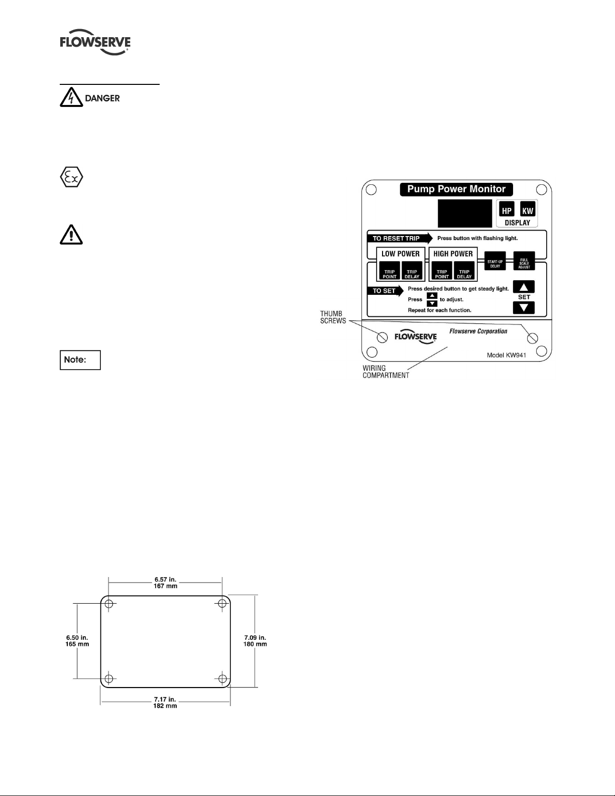
4.1 Location
The KW941 Display/Control module can be mounted
on the outside of the motor starter panel or a nearby
wall or structure. Use the four corner mounting screw
holes located below the see - through front cover
screws. Refer to Figure 4.1 for mounting dimensions.
The KW941 Display/Control module can be located
up to 30.5 m (100 ft.) from the motor lead that must
run through the current sensor (toroid). This is the
length limit for extending the toroid leads.
Figure 4.1
4.2 Electrical connections
Connections are made in the wiring compartment,
accessible by removing the separate cover plate on
the lower portion of the KW941. Loosen the two
thumbscrews to remove the cover plate (see Figure
4.2).
Figure 4.2
Entry for wiring/conduit is made by drilling, sawing or
punching the required hole(s) into the wiring
compartment area. Use caution when making access
holes to prevent damage to the internal components.
The following information is required for installation:
1) Motor Nameplate Full Load Power
2) Motor Nameplate Voltage and Hertz (Hz)
3) Control Volts (110 or 220/240 VAC) from
transformer between motor power phases.
4) Motor efficiency.
Record this information on the worksheet provided in
Section 8 of this manual.
4.2.1 Control Voltage
Refer to the product identification label on the outside
of the KW941 enclosure for the selected factory
preset VAC and HZ options (110/120 or 220/240
VAC, 50 or 60 HZ).
Page 8 of 24 flowserve.com
Page 9

KW941 Pump Power Monitor USER INSTRUCTIONS ENGLISH 71569285 02-12
can be used to supply the voltage. Otherwise, a
Never move jumpers when power is
on! It can damage the unit.
The Control Voltage (110 or 220/240 VAC) is
required to power the KW941 as well as to provide a
voltage sample for power computation.
The voltage (VAC) MUST be obtained
from a voltage transformer connected between
two phases of the three phase motor power leads.
If a control voltage transformer (with at least 15 VA
capacity) is already present between two phases, it
Figure 4.3
suitable transformer must be installed.
In the case of a 220/240 VAC three phase motor, the
voltage (VAC) can be obtained directly across two of
the phases, provided that the Display/Control module
is set for 220/240 VAC voltage operation.
The control voltage is connected to the KW941
Display/Control module using properly sized wires in
an appropriate conduit. Wire the control voltage
(VAC) to the KW941 terminal strip (TS1) as shown in
Figure 4.3. Table 4.1 describes the function of each
of the terminal strip positions.
Page 9 of 24 flowserve.com
Page 10

KW941 Pump Power Monitor USER INSTRUCTIONS ENGLISH 71569285 02-12
Screw #
Description
Notes
91.0
Table 4.1 Display/Control Unit Connection Terminals (TS1)
1 Ground Safety ground to connect units metal frame to earth ground
2 VAC Input
3 VAC Input
4 Hi Alarm NO
5 Hi Alarm NC
6 Hi Alarm common The common screw # for the HI Alarm relay contacts.
7 Lo Alarm NO
8 Lo Alarm NC
9 Lo Alarm common The common screw # for the LO Alarm relay contacts.
10 Reset +
11 Reset -
12 4-20 mA + Positive connection for the 4-20 mA output function (optional).
13 4-20 mA - Negative connection for the 4-20 mA output function (optional).
14 Current Sensor Input Current sensing toroid lead connection.
15 Current Sensor Input Current sensing toroid lead connection.
4.2.2 Current Sensor Set Up
The current senor (toroid) is shipped inside
the KW941 underneath the wiring compartment
cover.
NEVER MOVE JUMPERS WHEN
POWER IS ON!
When properly installed, the current sensing toroid
(see figure 4.4) normally is located inside the motor
starter panel with one of the three phase motor power
leads passing through its center one or more times.
The sensor's output leads are then connected to the
KW941 Display/Control module using an appropriate
conduit. Figure 4.4
AC control voltage, 110 VAC from control voltage transformer (220/240
VAC optional)
AC control voltage, 110 VAC from control voltage transformer (220/240
VAC optional)
The normally open (power on, not tripped) Hi Alarm relay contact
between TS1 screw # 4 and # 6. This contact will be closed upon a Hi
Alarm condition or loss of control voltage.
The normally closed (power on, not tripped) Hi Alarm relay contact
between TS1 screw # 5 and # 6. This contact will open upon a Hi
Alarm condition or loss of control voltage.
The normally open (power on, not tripped) LO Alarm relay contact
between TS1 screw # 7 and # 9. This contact will close upon a LO
Alarm condition or loss of control voltage.
The normally closed (power on, not tripped) LO Alarm relay contact
between TS1 screw # 8 and # 9. This contact will open upon a LO
Alarm condition or loss of control voltage.
Remote reset terminal. A momentary contact between TS1 # 10 and #
11 will reset the alarm relay contacts.
Remote reset terminal. A momentary contact between TS1 # 10 and #
11 will reset the alarm relay contacts.
To install the current sensor:
1) Determine the required KW941 Full Scale Power
(FS) by calculating your motor's required INPUT
Power:
PowerNameplateMotor
2)
EXAMPLE:
3) Locate your motor voltage in Table 4.2 by
reading down the Motor Volts column.
4) Read across the table row identified by your
motor voltage to locate the smallest KW941 Full
Scale Power value that is greater than or equal
to the motor's Input Power found in step 1. This
will be the KW941 Full Scale Power (FS).
Record this value on the configuration worksheet
in Section 8 of this manual.
If the motor's Input Power exceeds the FS
values listed in Table 4.2, use Table 4.3.
PowerInput
_ =
PowerInput =
10_HP
EfficiencyMotor
_
= 10.98 HP
__
Page 10 of 24 flowserve.com
will result in decreased sensitivity.
Using a FS value larger than required
Page 11

KW941 Pump Power Monitor USER INSTRUCTIONS ENGLISH 71569285 02-12
5) Determine the number of "turns" required by the
motor power lead through the toroid inner
diameter. Read up the table column from the
selected Full Scale Power (FS) found in step 3.
The number of turns shown in that column
header is the required number of passes the
motor power lead must make through the current
sensing toroid. Record the number of turns on
the installation and configuration worksheet in
Section 8 of this manual.
6) Loop the motor power lead the required number
of turns through the toroid. THIS LEAD MUST
NOT BE EITHER OF THE LEADS USED FOR
THE CONTROL VOLTAGE TRANSFORMER.
Turns are counted by the number of times the
motor lead passes through the toroid center.
See Figure 4.3 for an example of one turn
through the current sensing toroid. If the motor
power lead is too large to obtain the required
number of turns, select the next larger KW941
Full Scale Power (FS) and its corresponding
number of turns. The smallest possible FS at
the required motor voltage will give best results.
7) Connect the two leads coming from the current
sensing toroid to the KW941 TS1 (# 14 and #
15) as shown in Figure 4.3 and described in
Table 4.1. If extension leads are needed, use 24
AWG or larger wire up to 30.5 m (100 ft.) long.
Table 4.2
KW941 Full Scale Power "FS" (Jp5 set to X10 Range)
Motor Power @ 1 turn Power @ 2 turns Power @ 3 Turns Power @ 4 turns Power @ 5 Turns
Volts KW HP KW HP KW HP KW HP KW HP
575 14.0 18.8 7.0 9.4 4.7 6.3 3.5 4.7 2.8 3.8
460 11.2 15.0 5.6 7.5 3.7 5.0 2.8 3.8 2.2 3.0
415 10.0 13.5 5.0 6.8 3.4 4.5 2.5 3.4 2.0 2.7
400 9.7 13.0 4.8 6.5 3.2 4.3 2.5 3.3 1.9 2.6
380 9.2 12.4 4.6 6.2 3.0 4.1 2.3 3.1 1.8 2.5
230 5.6 7.5 2.8 3.8 1.8 2.5 1.4 1.9 1.1 1.5
208 5.0 6.8 2.5 3.4 1.7 2.3 1.3 1.7 1.0 1.4
Table 4.3
KW941 Full Scale Power "FS" (Jp5 set to X1 Range -- Default)
Motor Power @ 1 turn Power @ 2 turns Power @ 3 turns
Volts KW HP KW HP KW HP
575 140 188 69.9 93.8 46.6 62.5
460 112 150 55.9 75.0 37.3 50.0
415 101 135 50.4 67.7 33.6 45.1
400 96.9 130 48.6 65.2 32.4 43.5
380 92.5 124 46.2 62.0 30.8 41.3
230 55.9 75.0 27.9 37.5 18.6 25.0
208 50.5 67.8 25.3 33.9 16.8 22.6
For motor voltages not listed in Table 4.2 or 4.3,
calculate Full Scale Power as follows:
a) For 110 VAC KW941 models
V
FSPFSP
M
12
V
××=4
C
b) For 220/240 VAC KW941 models
V
FSPFSP
M
12
V
××=2
C
FSP1 = FS Power @ 460 VAC from Table 4.2 or
4.3
KW941 VAC terminals (# 2 and # 3). This voltage
normally is the output voltage of the control
transformer in the motor starter and must be
110/115/120 or 220/230/240 VAC.
For applications with motor nameplates above 150
HP (112 KW) @ 460 VAC, if the motor lead does
not fit through the supplied current sensor, or if
custom full scale settings are desired, contact your
nearest Flowserve sales representative or
distributor.
Control voltage is the voltage to the
VM = motor voltage
VC = control voltage (110 or 220/240 VAC)
Page 11 of 24 flowserve.com
Page 12

KW941 Pump Power Monitor USER INSTRUCTIONS ENGLISH 71569285 02-12
Figure 4.5
4.2.3 Jumper Settings
By default, Jumper Jp5 connections are
pins # 1 to # 2 (see Figure 4.5 and Table 4.4) which
is the “X1” range. This range is used for motors over
11.2 KW (15 HP).
For smaller motors, the jumper Jp5 may need to be
moved to pins # 2 and # 3, which is the “X10” range.
Review Tables 4.2 and 4.3 for setting the ranges for
a given Full Scale Power (FS).
Never move jumpers when power is
on!
Table 4.4
Hz Selection (Jp3) Range Select (Jp5)
Hz Connect Pins Range Connect Pins
50 3 to 4 X1 1 to 2 (Default)
60 1 to 2 and 3 to 4 X10 2 to 3
4.2.4 Alarm Relays
Use of a surge suppressor is recommended when
switching highly inductive loads such as a magnetic
motor starter coil.
In case of an alarm condition, alarm relay contacts
can be connected into the pump start/stop control
circuit in order to shut down the pump. Refer to
Figure 4.3 and Table 4.1 for alarm relay connections.
Relays are shown powered up, not tripped. The
relays may also be used for audible or visual alarms.
4.2.5 4-20 Milliamp Output
The output provides 4-20 milliamps proportional to
the KW941 full scale power. An external load of up to
600 Ohms can provide remote indication or input to
another device. The load is connected across TS1 #
12 (4-20 mA +) and TS1 # 13 (4-20 mA -) as
identified in Figure 4.3.
Page 12 of 24 flowserve.com
Page 13

KW941 Pump Power Monitor USER INSTRUCTIONS ENGLISH 71569285 02-12
5 SETUP AND OPERATION
These operations must be carried
out by fully qualified personnel.
The normal startup/reset sequence begins when
power is supplied to the KW941. The display will
flash "888" and the front panel LEDs will also flash.
The software revision number will then be displayed
briefly before the display returns to "0". The display
and front panel LEDs should be constant when this
sequence is complete.
Once installed and powered, set the control values
for the KW941 using the front panel Function buttons
and the up and down (↕) SET buttons. A button is
activated by pressing the slightly raised front panel
label area containing the desired function. Setup
should be performed prior to start-up of the pump
with power applied to the KW941.
Setup is accomplished by performing the following
steps to set various control values:
1) Select the power display mode, i.e. HP or KW.
2) Set the Full Scale Adjust value.
3) Set the Start-Up Delay timer value.
4) Set the Low Power Trip Point value.
5) Set the Low Power Trip Delay timer.
6) Set the High Power Trip Point value.
7) Set the High Power Trip Delay timer
We recommend that the setup information be
recorded on the Installation/ Setup Configuration
Worksheet form.
Function Adjustments
Select the appropriate function button to adjust
functions. A red LED on the button will illuminate
indicating the function is active. The function can then
be adjusted by pressing the -↕ SET arrow buttons to
obtain the necessary display value.
Pressing the HP or KW display button after pressing
another function button will cause the function adjust
button LED to go out and return the KW941 to normal
operation.
If no button is pressed within 15 seconds after a
function button has been pressed, the function adjust
button LED will go out and the KW941 will return to
normal operation.
5.1 Display Mode – Power Units
Selection
The KW941 can display power in either HP
(horsepower) or KW (Kilowatts). Select the desired
display units by depressing the HP or KW button. The
red LED will illuminate for the selected units.
The KW941 can be set up and operated in either
mode. Conversion between units is automatic when
display units are changed.
5.2 Full Scale Adjust
The KW941 can be scaled to display power to the
motor or power to the pump. The preferred setup is
pump power.
5.2.1 To display PUMP POWER
1) Calculate the Full Scale Adjustment setting
(FSA) by multiplying the Full Scale (FS) Power
obtained from Table #4 or 4a, (HP or KW) times
the motor efficiency factor in decimal format.
Record the FSA on the installation/setup
worksheet.
Example: Motor Volts = 460 VAC, Full Scale
power from Table #4 = 3.8 HP, and motor
efficiency = .93 (93%).
FSA = 3.8 HP X 0.93 = 3.5 HP
or
FSA = 2.8 KW X 0.93 = 2.6 KW
2) Depress the Full Scale Adjust button. The LED
on the button will illuminate, indicating that the
Full Scale Adjust function is active.
3) Press the -↕ SET arrows to obtain the Full Scale
Adjust setting on the display.
4) Press the HP or KW display mode button to
return to normal operation or any other function
button to activate that function's adjustment
feature.
The display will now indicate power to the pump
in the selected units.
Page 13 of 24 flowserve.com
Page 14

KW941 Pump Power Monitor USER INSTRUCTIONS ENGLISH 71569285 02-12
5.2.2 To display MOTOR POWER
1) Obtain the Full Scale power (HP or KW) from
Table #4. This will be the Full Scale Adjust
setting (FSA).
Example: Full Scale power = 3.8 HP.
FSA = 3.8 HP
or
FSA = 2.8 KW
2) Depress the Full Scale Adjust button. The LED
on the button will illuminate, indicating that the
Full Scale Adjust function is active.
3) Press the ↕ SET arrows to obtain the Full Scale
Adjust setting on the display.
4) Press the HP or KW display mode button to
return to normal operation or any other function
button to activate that function's adjustment
feature.
The display will now indicate power to the motor in
the selected units.
Unbalanced power line load conditions will
affect power readings.
5.3 Alarms
The KW941 provides LOW POWER (UNDERLOAD)
and HIGH POWER (OVERLOAD) alarm relays.
When wired into the pump's motor starter circuit, the
alarm relays can trip out the pump motor during
UNDERLOAD or OVERLOAD conditions. The alarms
are disabled for an adjustable period of time during
motor start-up (Start-Up Delay) to permit the pump to
reach normal operation.
The following information describes how to set up the
Start-Up Delay timer and alarms.
5.3.1 Start-Up Delay
The start-up delay is the amount of time in seconds
(0-999) that must expire after the pump motor has
been started and before the High Power and Low
Power functions become active.
5.3.1.1 Operation
When the pump is started, the START-UP DELAY
LED will flash for the set period of time and then go
out.
5.3.1.2 Setting the START UP DELAY
1) Press the START-UP DELAY button. The StartUp Delay LED will illuminate and the display will
show the timer value in seconds.
2) Adjust the value by pressing the ↕ SET arrow
buttons to obtain the desired time (0-999
seconds) on the display. It is recommended that
the delay be set to the minimum time required to
obtain a normal pump start-up (usually less than
5 seconds). Excessive delays leave the pump
un-protected which may result in damage to the
pump or motor.
3) Press the desired display mode HP or KW
button to turn off the Start-Up Delay LED and
return to normal operation (or any other function
button to activate that function's adjustment
feature).
5.3.2 Low Power Alarm
The Low Power Trip Point is the minimum power
level necessary to prevent the Low Power Alarm
relay from tripping. The normal state of the Low
Power Trip Point LED is off.
5.3.2.1 Operation
If a low power trip has occurred, the Low Power Trip
Point LED will blink and the Low Power Alarm Relay
will trip if the Low Power Trip Delay timer has
expired.
The Low Power Trip Delay is the amount of time in
seconds (0-999) that must expire before the Low
Power Alarm Relay will trip. The timer is activated
when the power level has fallen below the Low Power
Trip Point setting. The normal state of the Low
Power Trip Delay LED is off.
When the power level has fallen below the Low
Power Trip Point setting, the Low Power Trip Delay
LED will blink. If the power level increases above the
trip point setting before the delay timer value times
out, the blinking LED will then go out and the unit
returns to normal operation. If the power level
remains below the trip point longer than the delay
timer setting, the Low Power Trip Relay is activated.
The blinking Trip Delay LED will go out and the Trip
Point LED will blink alerting the operator to the
problem.
Page 14 of 24 flowserve.com
Page 15

KW941 Pump Power Monitor USER INSTRUCTIONS ENGLISH 71569285 02-12
To reset, press the Low Power Trip Point function
button (or use the remote reset feature). This will
cause the Low Power Trip Point LED to go out and its
alarm relay to be reset. The pump may be restarted
after resetting the alarm, however, it is strongly
recommended that you investigate the cause of the
alarm.
5.3.2.2 Setting the Low Power Trip Point
1) Pressing this function button will cause its LED
to illuminate. The current setting for the Low
Power Trip Point is displayed.
2) Press the ↕ SET arrow buttons to adjust the
setting.
3) After the trip point is set, press the HP or KW
button to return to normal operation (or any
other function button to activate that function's
adjustment feature).
Flowserve recommends the Low Power
Trip Point be set at the pump's power level for its
minimum continuous flow. This power level is
provided by Flowserve via the PC based pump
selection program (PROS+). If the information is not
readily available, contact your Flowserve sales
representative or local distributor. You may also
obtain a copy of the PROS+ program for in-plant use.
5.3.2.3 Setting the Low Power Trip Delay
1) Press the Low Power Trip Delay button. The
Trip Delay LED will illuminate indicating the
function is active. The current delay value in
seconds (0 to 999) will be displayed.
2) Press the ↕ SET buttons to display the desired
value.
3) Press the HP or KW button to turn off the
function's LED and return to normal operation
(or any other function button to activate that
function's adjustment feature).
The delay time value should be set to
accommodate normal process fluctuations (usually 5
seconds or less). Excessive delays allow the pump
to operate at low power (low flow) conditions which
may result in damage to the pump.
5.3.3 High Power Alarm
The High Power Trip Point is the power level that, if
exceeded, will cause the High Power Alarm relay to
trip after the High Power Trip Delay has expired. The
normal state of the high power trip point LED is off.
5.3.3.1 Operation
If a high power trip has occurred, the High Power Trip
Point LED will blink and the High Power Alarm Relay
will trip if the High Power Trip Delay timer has
expired.
The High Power Trip Delay is the amount of time in
seconds (0-999) that must expire before the high
power alarm relay will trip. The timer is activated
when the power level increases above the High
Power Trip Point setting. The normal state of the
High Power Trip Delay LED is off.
When the power level increases above the High
Power Trip Point setting, the High Power Trip Delay
LED will blink. If the power level decreases below
the trip point setting before the delay timer value
times out, the blinking LED will then go out and the
unit returns to normal operation. If the power level
remains above the trip point longer than the delay
timer setting, the high power relay trips. The blinking
Trip Delay LED will go out and the Trip Point LED will
blink.
To reset, press the High Power Trip Point function
button (or use the remote reset feature). This will
cause the High Power Trip Point LED to go out and
its alarm relay to be reset. The pump may be
restarted after resetting the alarm, however, it is
strongly recommended that you investigate the cause
of the alarm.
5.3.3.2 Setting the High Power Trip Point
1) Pressing this function button will cause its LED
to illuminate. The current setting for the High
Power Trip Point is displayed.
2) Press the ↕ SET arrow buttons to adjust the
setting.
3) After the trip point is set, press the HP or KW
button to return to normal operation (or any
other function button to activate that function's
adjustment feature).
Flowserve recommends the High Power
Trip Point be set at one of the following levels:
a) The end of curve power shown on the pump
performance curve.
b) The maximum rated power of the motor.
c) The power rating of the magnetic coupling of a
mag drive or canned motor pump motor.
Page 15 of 24 flowserve.com
Page 16

KW941 Pump Power Monitor USER INSTRUCTIONS ENGLISH 71569285 02-12
The High Power Trip Point setting is usually
determined by the lowest value of the above three
conditions, however, specific pumping applications
may benefit from lower setting. For additional
information, contact your Flowserve sales
representative or local distributor.
5.3.3.3 Setting the High Power Trip Delay
1) Press the High Power Trip Delay button. The
Trip Delay LED will illuminate indicating the
function is active. The current delay value in
seconds (0 to 999) will be displayed.
2) Press the ↕ SET buttons to display the desired
value.
3) Press the HP or KW button to turn off the
function's LED and return to normal operation
(or any other function button to activate that
function's adjustment feature).
The delay time value should be set to
accommodate normal process fluctuations (usually 2
seconds or less). Excessive delays allow the pump
to operate at high power conditions which may result
in damage to the pump or motor.
5.3.4 Resetting Alarms
Alarms, indicated by a blinking Low Power or High
Power Trip Point LED, can be reset by any of three
methods.
a) MANUAL: Press Trip Button with the flashing
LED.
b) REMOTE: Momentary contact closure between
Reset + and Reset - on TS1. See specifications
for contact requirements.
c) AUTOMATIC: In automatic reset mode, an alarm
condition will cause the selected alarm relay(s)
to remain in the tripped state for 10 seconds
before automatically resetting.
5.3.5 Activating Automatic Reset Mode
1) Press and hold the TRIP DELAY button until the
TRIP DELAY displayed value is flashing. This
indicates that the unit is now in automatic mode.
2) Press the HP or KW button to return to normal
operating mode.
5.3.6 De-activating Automatic Reset Mode
1) To return to manual alarm reset operation press
and hold the TRIP DELAY button until the TRIP
DELAY display value stops flashing.
2) Press the HP or KW button to return to normal
operating mode.
5.4 Demo Mode
Using the Demo Mode can be helpful in verifying
whether or not the alarm contacts are functional.
Varying the simulated input power in Demo Mode will
permit simulated alarm conditions causing the alarm
relay(s) to trip. This will enable verification of the
alarm contact wiring/wiring logic into the motor
start/stop circuit.
Changing time delays and setpoints, then
successfully causing alarm relays to trip while in
Demo Mode may indicate that a problem is due to
external causes such as wiring errors, misapplication,
or improper setup.
To enter the Demo Mode:
• press the "HP" button, and then the UP (↑)
setting arrow on the front panel consecutively.
The "HP" LED will blink indicating that the Demo
Mode is operational.
• Repeat this sequence to exit the Demo Mode.
• Use the UP (↑) and DOWN (↓) setting arrows to
change the readout to simulate a motor load.
The display will increase or decrease as the
arrow buttons are pressed. Moving the load
above the High Power Trip Point or below the
Low Power Trip Point will activate the alarm
contacts (after Trip Delay has expired).
• The Startup Delay may need to be extended to
move the simulated load between the Trip
Points.
5.5 Current Sensor Field Replacement
The current sensor (toroid) can be replaced in the
field if required, but it must be calibrated to the
KW941 using the following procedure.
With the current sensor connected to the KW941 and
power to the unit but the motor not running (no
current through the lead going thru the sensor):
1. Press and hold in the “KW” button until the
display changes, a number will be displayed.
2. Release the “KW” button and immediately
press and release the up arrow “SET” button.
3. The display will return to zero and the sensor
will be calibrated for that unit. Select the
desired display units. The unit is now ready
for normal operation.
Page 16 of 24 flowserve.com
Page 17

KW941 Pump Power Monitor USER INSTRUCTIONS ENGLISH 71569285 02-12
6 MAINTENANCE
The KW941 Pump Power Monitor should not require
any routine maintenance outside of wiping down the
front cover occasionally.
It is the plant operator's responsibility to ensure
that all maintenance, inspection and assembly work
is carried out by authorized and qualified personnel
who have adequately familiarized themselves with
the subject matter by studying this manual in detail.
(See also section 1.6.2.)
Before restarting the machine, the relevant
instructions listed in section 5, Setup and Operation
must be observed.
Place a warning sign on the starting device:
"Machine under repair: do not start".
With electric drive equipment, lock the main switch
open and withdraw any fuses. Put a warning sign on
the fuse box or main switch:
"Machine under repair: do not connect".
6.1 Spare parts
No spare parts are needed. The internal fuse is not
meant to be accessed by the customer per CE
requirements. The current sensor (toroid) is robust,
but the leads can be broken off if handled roughly.
Contact your local Flowserve sales representative to
order a new toroid if the leads are damaged. Follow
the procedure in Section 5.5 to calibrate the new
toroid to the KW941 unit.
6.2 Tools required
A flat blade screwdriver, wire cutter, and wire stripper
are all that should be required to work on the wiring
going to the KW941 Pump Power Monitor once it is
installed.
7 FAULTS: CAUSES AND REMEDIES
Troubleshooting
The purpose of this guide is to supply general
information on how to troubleshoot problems related
to startup and operation of the KW941 Pump Power
Monitor. It is intended only as a guide and cannot
cover every situation. If a problem exists that is not
covered by one of the examples, then contact a
Flowserve Sales Engineer or
Distributor/Representative for assistance.
General Guidelines
• The KW941 Pump Power Monitor is intended for
use on fixed frequency, steady, non-pulsating
loads. The unit is not intended for use with
variable frequency drives.
• When troubleshooting, never swap electronics
from one unit to another. This will cause
operational problems and void any warranty
claim.
• It is often helpful to isolate the monitor to
determine if the cause of a problem is internal to
the KW941 or a part of the external wiring
system. By removing all connections except for
the voltage and current sensing toroid, the
problem can normally be isolated to either the
monitor itself or to the external wiring.
• Each KW941 has an internal "DEMO MODE"
which can be helpful in verifying the correct
function of the unit. See Section 5.4 for
instructions on how to use this mode.
• Typical writing configurations for utilizing alarm
relays are shown in Section 8 as Figures 8.1
and 8.2 for reference.
Page 17 of 24 flowserve.com
Page 18

KW941 Pump Power Monitor USER INSTRUCTIONS ENGLISH 71569285 02-12
FAULT SYMPTOM
Unit will not power up (i.e., no lights)
Display locks up or all LEDs continuously flashing
⇓⇓⇓⇓
Power readings higher than expected
⇓⇓⇓⇓
Power readings lower than expected
⇓⇓⇓⇓
Power readings drifting or inconsistent
⇓⇓⇓⇓
Non-zero reading when equipment not running
⇓⇓⇓⇓
Power reading flashing
⇓⇓⇓⇓
Unit repeats startup/reset cycle when motor is tripped due to alarm, or when the motor is started
⇓⇓⇓⇓
⇓⇓⇓⇓
Monitor will not shut off motor
Cannot start motor
⇓⇓⇓⇓
⇓⇓⇓⇓
No AC power to unit.
Voltage supply different than unit rating. Verify supply voltage is the same as unit rating (110V or 220V).
Unit held in reset mode (closed
switch/contact at remote reset terminals
# 10 and # 11).
Internal fault.
Corrupted memory or internal fault. Reset unit (power off/on) to clear the fault. If normal operation
Equipment operating at higher than
expected load.
Incorrect KW941 installation/setup. 1. Verify correct number of turns of motor power lead through
Current sensing toroid on wrong motor
lead.
Incorrect voltage sample. Verify voltage sample taken from two phases supplying a three-
Equipment operating at lower than
expected load.
Incorrect KW941 installation/setup. 1. Verify correct number of turns of motor power lead through
Current sensing toroid on wrong motor
lead.
Incorrect voltage sample. Verify voltage sample taken from two phases supplying a three-
Current sensing toroid leads too long. Limit lead length to 30.5 m (100 ft.).
Equipment load fluctuating. Verify equipment operating conditions are at designed levels.
Current sensing toroid on wrong motor
lead.
PROBABLE CAUSES POSSIBLE REMEDIES
Check for proper voltage supply to terminals # 2 and # 3.
Use normally open switch/contact for remote reset.
Return unit through the sales representative to supplier for
evaluation and repair.
is not seen, return the unit through the sales representative to
supplier for evaluation and repair.
1. Verify equipment operating conditions are at designed levels.
2. Check equipment for abnormal operation (e.g., excessive
mechanical rubbing).
current sensing toroid.
2. Verify correct Full Scale Adjustment setting.
3. Verify correct Full Scale Range is selected (X1 or X10).
4. Verify correct frequency is selected (50 Hz or 60 Hz).
Verify current sample is not taken from either of the lead from
which the voltage sample is taken.
phase motor.
1. Verify equipment operating conditions are at designed levels.
2. On mag drive pumps, check for magnet decoupling.
3. Check for closed valve or other flow restriction.
4. Check motor to pump coupling.
current sensing toroid.
2. Verify correct Full Scale Adjustment setting.
3. Verify correct Full Scale Range is selected (X1 or X10).
4. Verify correct frequency is selected (50 Hz or 60 Hz).
Verify current sample is not taken from either of the lead from
which the voltage sample is taken.
phase motor.
Verify current sample is not taken from either of the lead from
which the voltage sample is taken.
Page 18 of 24 flowserve.com
Page 19

KW941 Pump Power Monitor USER INSTRUCTIONS ENGLISH 71569285 02-12
FAULT SYMPTOM
Unit will not power up (i.e., no lights)
Display locks up or all LEDs continuously flashing
⇓⇓⇓⇓
Power readings higher than expected
⇓⇓⇓⇓
Power readings lower than expected
⇓⇓⇓⇓
Power readings drifting or inconsistent
⇓⇓⇓⇓
Non-zero reading when equipment not running
⇓⇓⇓⇓
Power reading flashing
⇓⇓⇓⇓
Unit repeats startup/reset cycle when motor is tripped due to alarm, or when the motor is started
⇓⇓⇓⇓
⇓⇓⇓⇓
⇓⇓⇓⇓
Monitor will not shut off motor
Cannot start motor
⇓⇓⇓⇓
Incorrect voltage sample. Verify voltage sample taken from two phases supplying a three-
Poor or open connection from current
sensing toroid leads to terminals # 14
and # 15.
Current input circuit damaged because
of overload from selecting the wrong Full
Scale Range (X10 instead of X1) or
having too many turns through the toroid.
Wrong input voltage frequency setting. Verify correct frequency is selected (50 Hz or 60 Hz) per
Wrong current sensing toroid used with
unit.
Other load exists on terminal # 14 and #
15 or on the leads of the toroid.
Over-range condition. 1. Verify equipment operating conditions are at designed levels.
Electrical interference caused by KW941
relay contacts switching too large or
unsuppressed load.
Nearby equipment causing interference. Relocate the KW941 unit.
Improper application of remote reset. Use normally open switch/contact for remote reset.
Interference picked up by reset leads. 1. Relocate the leads.
Incorrect alarm inputs. Check equipment performance characteristics to determine
Alarm contact not wired, or improperly
wired into motor start/stop circuit.
KW941 not powered. Check voltage supply to unit.
KW941 tripped due to previous alarm
condition.
Internal fault not allowing contacts to
close.
Alarm contacts wired improperly into
motor start/stop circuit.
PROBABLE CAUSES POSSIBLE REMEDIES
phase motor.
Check connections.
Return unit through the sales representative to supplier for
evaluation and repair.
jumper Jp3.
Verify that the sensor being used is the same one shipped with
the unit. If it is not, see section 5.5 for the calibration
procedure.
Eliminate all connection except those for the KW941.
2. Verify correct installation/setup (see “power readings higher
or lower than expected”).
1. Verify load is within relay ratings.
2. Add arc suppression device to motor starting coil.
3. Use interposing relay (a separate relay switched by the
KW941 relay) to switch load. See schematic in Figure 8.2.
2. Use twisted shielded pair for reset leads.
appropriate set points.
Verify proper wiring of alarm contacts into motor start/stop
circuit.
Check equipment for cause of alarm. Reset unit using manual,
remote, or auto reset features.
Reset unit (power off/on) to clear the fault. If normal operation
is not seen, return the unit through the sales representative to
supplier for evaluation and repair.
Verify proper wiring of alarm contacts into motor start/stop
circuit.
Page 19 of 24 flowserve.com
Page 20

KW941 Pump Power Monitor USER INSTRUCTIONS ENGLISH 71569285 02-12
100
8 PARTS LIST AND DRAWINGS
Installation / Setup Configuration Worksheet
Pump/Equipment Identification ______________________________
Location KW941 ______________________________
Model / Part Number ______________________________
Serial Number ______________________________
Motor Data
Motor Nameplate Full Load Power ________ KW HP
Motor Nameplate Voltage ________ Volts
Motor Nameplate Frequency ________ Hertz (HZ)
Control Voltage from Transformer ________ 110 V or 220/240 V
Motor Efficiency =
Calculate: Input Power =
%__ EfficiencyMotor
________
PowerLoadFull __
________
iencyMotorEffic
Current Sensor
Full Scale Power (FS) [Table 4.2 or 4.3] ________ KW HP
Number of Turns through Toroid [Table 4.2 or 4.3] ________ Turns
Display Settings
Units ________ KW or HP
Full Scale Power (FS) [from Table 4.2 or 4.3] ________ KW HP
Calculate: Full Scale Adjust =
Full Scale (FS) x Motor Efficiency ________ KW HP
Start-up Delay ________ Seconds
Low Power Trip Point ________ KW HP
Low Power Trip Delay ________ Seconds
High Power Trip Point ________ KW HP
High Power Trip Delay ________ Seconds
Fault Reset Method
Local (from keypad) ________
Remote (TS1) ________
Automatic ________
Page 20 of 24 flowserve.com
Page 21

KW941 Pump Power Monitor USER INSTRUCTIONS ENGLISH 71569285 02-12
Figure 8.1
Schematic showing wiring arrangement used to shut off motor in case of HIGH or LOW Alarm and
provide 120 VAC to alarm indicators or other devices.
Page 21 of 24 flowserve.com
Page 22

KW941 Pump Power Monitor USER INSTRUCTIONS ENGLISH 71569285 02-12
Figure 8.2:
Schematic showing wiring arrangement used to shut off motor in case of HIGH or LOW Alarm and
provide 120 VAC to alarm indicators or other devices (interposed relay).
Page 22 of 24 flowserve.com
Page 23

KW941 Pump Power Monitor USER INSTRUCTIONS ENGLISH 71569285 02-12
9 CERTIFICATION
Certificates, determined from the contract
requirements, are provided with these instructions
where applicable. Examples are certificates for CE
marking and ATEX marking etc. If required, copies of
other certificates sent separately to the Purchaser
should be obtained from Purchaser for retention with
these User Instructions.
Statement on ATEX Compliance
The KW941 Pump Power Monitor must not be
installed in a potentially explosive atmosphere, but is
compliant with Ignition Prevention Level 1 in EN
13463-6 and so it can provide protection, by control
of ignition source ‘b’, of equipment of classification
Category 2 and 3, which is operating in a potentially
explosive atmosphere, (Zones -- 1, 21, 2 and 22).
The KW941 is not ATEX marked as an independent
device.
If the KW941 is used to monitor and alarm but not
automatically shut down, it shall still not be used in a
potentially explosive atmosphere, but there is no
restriction on its use with equipment in the potentially
explosive atmosphere.
If the KW941 is purchased separately to a Flowserve
pump/motor set, the user is responsible for the risk
assessment of the complete equipment.
The Flowserve KW941 Pump Power Monitor has
the following approvals:
The KW941 carries a CSA Certificate of Compliance
to Canadian and U.S. standards, Certificate Number:
LR 108009-1, dated 2007/08/09. Details are as
follows:
Products:
Class 3211 07 - Industrial Control Equipment Miscellaneous Apparatus
Class 3211 87 - Industrial Control equipment Miscellaneous Apparatus - CERTIFIED TO U.S.
STANDARDS
Applicable requirements:
CAN/CSA-C22.2 No. 14-05 - Industrial Control
Equipment
CAN/CSA-C22.2 No. 94-M91 - Special Purpose
Enclosures
UL Std No. 508 - Industrial Control Equipment
The "C" and "US" indicators next to the CSA Mark
signifies that the product was tested to applicable
ANSI/UL and CSA Standards, for use in the U.S. and
Canada.
In addition to the CSA Certification, theKW941 also
carries an EC-Declaration of Conformity:
Article 10.1 of the Directive 89/336/EEC (EMCDirective) in accordance with the following standards
or standardized documents:
EN 55 011:1991 Gr. 1 Kl.A Emission EMA
EN 61 000-3-2:1995 EMA Harmonics
EN 61 000-3-3:1995 EMA, Voltage Fluctuations
EN 50 082-2:1995 Immunity EMB
Appendix III of the Directive 73/23/EEC (Low Voltage
Directive)
IEC 1010-1:90 +A1:92 +A2:95
Test Reports of TUV Rheinland, Product Safety
GmbH, 51101 Cologne, Germany
No. P9612 781 E01 (EMC Test report)
No. E 9712536 E02 (Low Voltage Directive test
report)
10 OTHER RELEVANT
DOCUMENTATION AND MANUALS
10.1 Supplementary user instructions
Supplementary instructions such as for using the
KW941 Power Monitor for applications over 112 KW
(150 hp) or further clarification on how to use the 4-20
mA output are available. Have your local sales
representative contact Flowserve Engineering to
discuss your needs and get copies of the
supplementary instructions.
10.2 Change Notes
If any changes, agreed with Flowserve Pump
Division, are made to the product after it is supplied,
a record of the details should be maintained with
these User Instructions.
Page 23 of 24 flowserve.com
Page 24

KW941 Pump Power Monitor USER INSTRUCTIONS ENGLISH 71569285 02-12
Your Flowserve factory contact:
Flowserve Pump Division
3900 Cook Boulevard
Chesapeake, VA 23323-1626 USA
Telephone +1 757 485 8000
Fax +1 757 485 8149
Flowserve Pumps
Flowserve GB Limited
Lowfield Works, Balderton
Newark, Notts NG24 3BU
United Kingdom
Telephone (24 hours): +44 1636 494 600
Sales & Admin Fax: +44 1636 705 991
Repair & Service Fax: +44 1636 494 833
Email: newarksales@flowserve.com
Your local Flowserve representative:
To find your local Flowserve representative please
use the Sales Support Locator System found at
www.flowserve.com
FLOWSERVE REGIONAL
SALES OFFICES:
USA and Canada
Flowserve Corporation
5215 North O’Connor Blvd.,
Suite 2300
Irving, Texas 75039-5421, USA
Telephone +1 972 443 6500
Fax +1 972 443 6800
Europe, Middle East, Africa
Flowserve FSG – Italy
Worthing S.r.l.
Via Rossini 90/92
20033 Desio (Milan), Italy
Telephone +39 0362 6121
Fax +39 0362 628 882
Latin America and Caribbean
Flowserve Corporation
6840 Wynnwood Lane
Houston, Texas 77008, USA
Telephone +1 713 803 4434
Fax +1 713 803 4497
Asia Pacific
Flowserve Pte. Ltd
10 Tuas Loop
Singapore 637345
Telephone +65 6771 0600
Fax +65 6862 2329
Page 24 of 24 flowserve.com
 Loading...