

Page 1
USER INSTRUCTIONS
®
Worthington
pumps
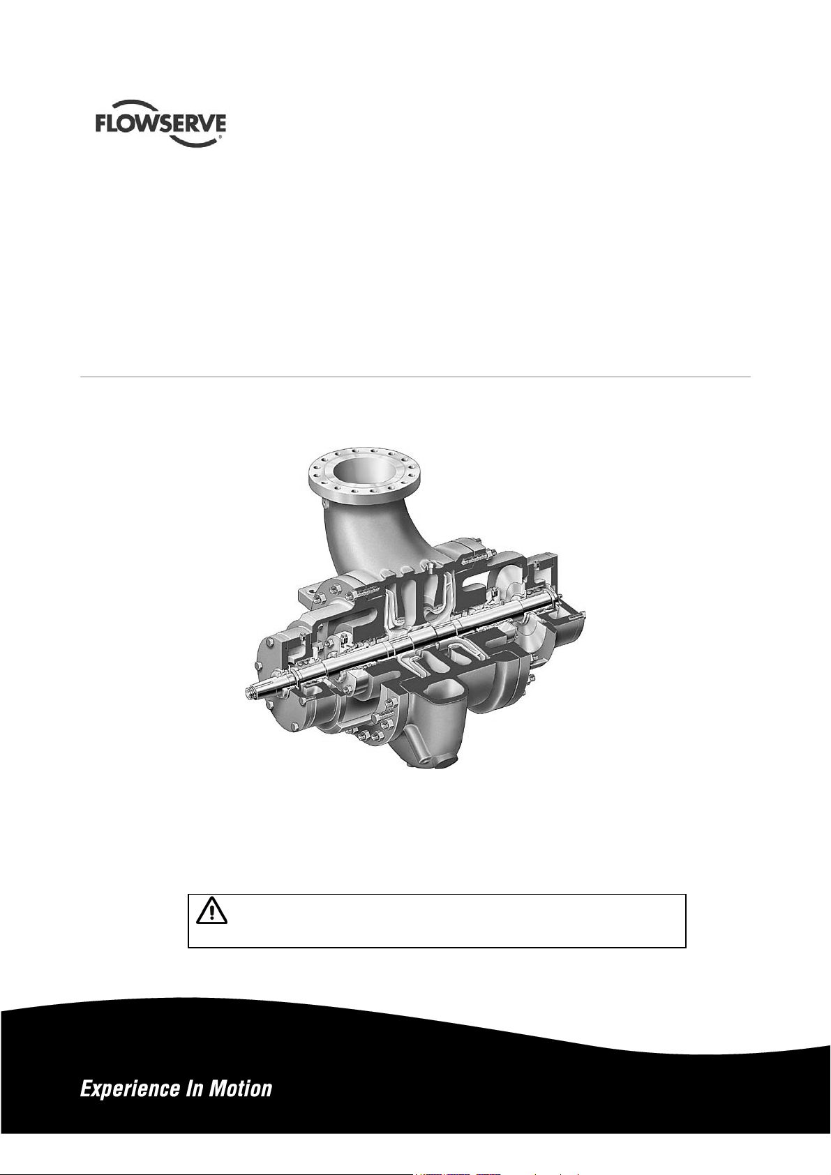
HED/HED-DS centrifugal
Installation
Operation
Double stage, double suction, radially split volute type
centrifugal pumps
PCN=85392695 –06/14 (E) Original instructions
Maintenance
These instructions must be read prior to installing,
operating, using and maintaining this equipment.
Page 2

HED/HED-DS USER INSTRUCTIONS ENGLISH 85392695 – 06/14
CONTENTS
PAGE
CONTENTS ............................................................... 2
1 INTRODUCTION AND SAFETY ............................ 4
1.1 General ............................................................ 4
1.2 CE marking and approvals ............................... 4
1.3 Disclaimer ........................................................ 4
1.4 Copyright .......................................................... 4
1.5 Duty conditions ................................................ 4
1.6 Safety ............................................................... 5
1.7 Nameplate and safety labels ............................ 8
1.8 Specific machine performance ......................... 8
1.9 Noise level ..................... ................................... 8
2 TRANSPORT AND STORAGE ... .... ....... .... .... .... .. 10
2.1 Consignment receipt and unpacking.............. 10
2.2 Handling ......................................................... 10
2.3 Lifting ................................. ............................. 10
2.4 Storage ................... ........................................ 11
2.5 Recycling and end of product life ................... 12
3 PUMP DESCRIPTION .......................................... 13
3.1 Configurations ................................................ 13
3.2 Nomenclature ................................................. 13
3.3 Design of major parts ..................................... 13
3.4 Performance and operating limits .................. 14
4 INSTALLATION ..................................................... 15
4.1 Location .................. ........................................ 15
4.2 Part assemblies ............................................. 15
4.3 Foundation .................................................... 15
4.4 Grouting ......................................................... 17
4.5 Initial alignment ............................................ .. 18
4.6 Piping ............................ ................................ 20
4.7 Final shaft alignment check ........................... 22
4.8 Electrical connections .................................... 22
4.9 Protection systems ......................................... 22
PAGE
7 FAULTS; CAUSES AND REMEDIES .................... 45
8 PARTS LIST AND DRAWINGS ............................ 47
9 CERTIFICATION ................................................... 62
10 OTHER RELEVANT DOCUMENTATION AND
6.4 Recommended spares (according to API) ..... 35
6.5 Tools required ................................................. 35
6.6 Fastener torques .................... ........................ 36
6.7 Disassembly ................................................... 37
6.8 Examination of parts ....................................... 39
6.9 Assembly ........................................................ 42
MANUALS ............................................ ............ 62
10.1 Supplementary User Instruction manuals .... 62
10.2 Change notes ............................................... 62
10.3 Additional sources of information ................. 62
5 COMMISSIONING, START-UP, OPERATION AND
SHUTDOWN .................................................... 23
5.1 Pre-commissioning procedure ....................... 23
5.2 Pump Lubricants ............................................ 28
5.3 Direction of rotation ....................................... 30
5.4 Guarding ....................................................... 31
5.5 Priming and auxiliary supplies ..... ... .... .... .... .. 31
5.6 Starting the pump .......................................... 31
5.7 Operating checks .......................................... 31
5.8 Normal Start Up ............................................. 33
5.9 Stopping the pump ......................................... 33
5.10 Hydraulic, mechanical and ........................... 33
electrical duty ....................................................... 33
6 MAINTENANCE .............................................. ...... 33
6.1 General ................................................ .......... 33
6.2 Maintenance schedule ................................... 34
6.3 Spare parts..................................................... 35
Page 2 of 64
Page 3

HED/HED-DS USER INSTRUCTIONS ENGLISH 85392695 – 06/14
INDEX
PAGE
Additional sources of information (10.3) ............. 62
Alignment methods (4.5.2) ................................. 18
Assembly (6.9) .................................................... 42
Associated equipment (2.4.1.5) .......................... 12
Avoiding excessive surface temperatures(1.6.4.3)7
Bearings (5.7.3) .................................................. 32
CE marking and approvals (1.2) ........................... 4
Certification (9) ................ .... ... .... .... .... .... ... .... .... . 62
Change notes (10.2) .................................. .... .... . 62
Commissioning, startup, operation (5)................ 23
Configurations (3.1) ............................................ 13
Consignment receipt and unpacking (2.1) .......... 10
Copyright (1.4) ...................................................... 4
Design of major parts (3.3) ................................. 13
Direction of rotation (5.3) .................................... 30
Disassembly (6.7) ............................................... 37
Discharge piping (4.6.3) ..................................... 21
Disclaimer (1.3) ..................................................... 4
Dismantling of thrust bearing (6.7.2) .................. 38
Dismantling of line bearing (6.7.3) ...................... 38
Disassembly of rotor (6.7.4) ............................... 39
Duty conditions (1.5) ............................................. 4
Electrical connections (4.8) ................................ 22
Examination of parts (6.8) ......................... .... ..... 39
Fastener torques (6.6) ........................................ 36
Faults; causes and remedies (7) ........................ 45
Foundation (4.3) ..................... .... .... ........ ... .... .... . 15
Grouting (4.4) ...................................................... 17
Guarding (5.4) ..................................................... 31
Handling (2.2) ..................................................... 10
Hydraulic, mechanical and electrical duty (5.10) . 33
Initial alignment (4.5) ......................................... . 18
Installation (4) ..................................................... 15
Introduction and safety (1) .................................... 4
Inspection and maintenance (2.4.1.3) ................ 11
Lifting (2.3) .......................................................... 10
Location (4.1) ...................................................... 15
Long term storage (2.4.1) ................................... 11
Lubrication (5.1.1) ............................................... 23
Maintenance to avoid the hazard (1.6.4.7) ........... 8
Maintenance (6) .................................................. 33
Maintenance schedule (6.2) ............................... 34
Marking (1.6.4.2) ................................................... 7
Mechanical seals (6.8.3) ..................................... 40
Nameplate and safety labels (1.7) ............... ... .... . 8
Noise level (1.9) ................ ................................... 8
Ordering of spares (6.3.1) .................................. 35
Other relevant documentation and manuals(10) 62
Parts list and Drawings (8) ................................. 47
Performance and operating limits (3.4) .............. 14
Personnel qualification and training (1.6.2) .......... 5
Piping (4.6) ......................................................... 20
Pressure and/or flow control (3.4.8) ................... 15
Preventing the build up of explosive mix. (1.6.4.4) 7
Preventing sparks (1.6.4.5) .................................. 8
Preventing leakage (1.6.4.6) ............................... . 8
Products used in potentially explosive atm. (1.6.4)6
Protection systems (4.9) .................................... 22
Primary and auxiliary supplies (5.5) ................... 31
Pump description (3) .......................................... 13
Pumps with mechanical seals (4.6.5)................. 22
Recommended spares (6.4) ............................... 35
Recycling and end of product life (2.5)............... 12
Routine inspection (daily/weekly) (6.2.1) ........... 34
Safety (1.6) ............. .............................................. 5
Safety action (1.6.3) ............................................. 5
Safety labels (1.7.2) ............................................. 8
Scope of compliance (1.6.4.1) ............................. 6
Spare parts (6.3) ................................................ 35
Specific machine performance (1.8) .................... 8
Starting the pump (5.6) ...................................... 31
Stopping the pump (5.9) ..................................... 33
Storage (2.4) ...................................................... 11
Storage of spares (6.3.2) ................................... 35
Suction piping (4.6.2) ........ .... .... ....... .... .... .... .... .. 21
Summary of safety markings (1.6.1) .................... 5
Supplementary user instructions (10.1) ............. 62
Thermal control (3.4.7) ....................................... 15
Tools required (6.5) ............................................ 35
Transport and storage (2) .................................. 10
Page 3 of 64
Page 4
HED/HED-DS USER INSTRUCTIONS ENGLISH 85392695 – 06/14
1 INTRODUCTION AND SAFETY
1.1 General
These instructions must always be kept
close to the product's operating location or
directly with the product.
Flowserve's products are designed, developed and
manufactured with state-of-the-art technologies in
modern facilities. The unit is produced with great care
and commitment to continuous quality control,
utilizing sophisticated quality techniques, and safety
requirements.
Flowserve is committed to continuous quality
improvement and being at service for any further
information about the product in its installation and
operation or about its support products, repair and
diagnostic services.
These instructions are intended to facilitate
familiarization with the product and its permitted use.
Operating the product in compliance with these
instructions is important to help ensure reliability in
service and avoid risks. The instructions may not take
into account local regulations; ensure such
regulations are observed by all, including those
installing the product. Always coordinate repair
activity with operations personnel, and follow all plant
safety requirements and applicable safety and health
laws/regulations.
These instructions must be read prior to
installing, operating, using and maintaining the
equipment in any region worldwide. The
equipment must not be put into service until all
the conditions relating to safety, noted in the
instructions, have been met. Failure to follow and
apply the present user instructions is considered
to be misuse. Personal injury, product damage,
delay or failures caused by misuse are not
covered by the Flowserve warranty.
1.2 CE marking and approvals
It is a legal requirement that machinery and
equipment put into service within certain regions of
the world shall conform with the applicable CE
Marking Directives covering Machinery and, where
applicable, Low Voltage Equipment, Electromagnetic
Compatibility (EMC), Pressure Equipment Directive
(PED) and Equipment for Potentially Explosive
Atmospheres (ATEX).
Where applicable, the Directives and any additional
Approvals, cover important safety aspects relating to
machinery and equipment and the satisfactory
provision of technical documents and safety
instructions. Where applicable this document
incorporates information relevant to these Directives
and Approvals. To confirm the Approvals applying
and if the product is CE marked, check the serial
number plate markings and the Certification, see
section 9, Certification.
1.3 Disclaimer
Information in these User Instruc tions is believed
to be reliable. In spite of all the efforts of
Flowserve to provide sound and all necessary
information the content of this man ual may appea r
insufficient and is not guaranteed by Flowserv e as
to its completeness or accuracy.
Flowserve manufactures products to exacting
International Quality Management System Standards
as certified and audited by external Quality
Assurance organisations. Genuine parts and
accessories have been designed, tested and
incorporated into the products to help ensure
continued product quality and performance in use. A s
Flowserve cannot test parts and accessories sourced
from other vendors the incorrect incorporation of such
parts and accessories may adversely affect the
performance and safety features of the products. The
failure to properly select, install or use authorised
Flowserve parts and accessories is considered to be
misuse. Damage or failure caused by misuse is not
covered by Flowserve's warranty. In addition, any
modification of Flowserve products or removal of
original components may impair the safety of these
products in their use.
1.4 Copyright
All rights reserved. No part of these instructions may
be reproduced, stored in a retrieval system or
transmitted in any form or by any means without prior
permission of Flowserve Corporation.
1.5 Duty conditions
This product has been selected to meet the
specifications of your purchaser order. The
acknowledgement of these conditions has been sent
separately to the Purchaser. A copy should be kept
with these instructions.
The product must not be operated beyond
the parameters specified for the application. If
there is any doubt as to the suitability of the
product for the application intended, contact
Flowserve for advice, quoting the serial number.
Page 4 of 64
Page 5
HED/HED-DS USER INSTRUCTIONS ENGLISH 85392695 – 06/14
If the conditions of service on your purchase order
are going to be changed (for example liquid pumped,
temperature or duty) it is requested that the user
seeks Flowserve’s written agreement before start up.
1.6 Safety
1.6.1 Summary of safety markings
These User Instructions contain specific safety
markings where non-observance of an instruction
would cause hazards. The specific safety markings
are:
This symbol indicates electrical safety
instructions where non-compliance will involve a high
risk to personal safety or the loss of life.
This symbol indicates safety instructions where
non-compliance would affect personal safety and
could result in loss of life.
This symbol indicates “hazardous and toxic fluid”
safety instructions where non-compliance would affect
personal safety and could result in loss of life.
This symbol indicates safety
instructions where non-compliance will involve some
risk to safe operation and personal safety and would
damage the equipment or property.
This symbol indicates explosive atmosphere
zone marking according to ATEX. It is used in safety
instructions where non-compliance in the hazardous
area would cause the risk of an explosion.
Always coordinate repair activity with operations and
health and safety personnel, and follow all plant
safety requirements and applicable safety and health
laws and regulations.
1.6.3 Safety action
This is a summary of conditions and actions to help
prevent injury to personnel and damage to the
environment and to equipment. For p roducts used in
potentially explosive atmospheres section 1.6.4 also
applies.
PREVENT EXCESSIVE EXTERNAL
PIPE LOAD
Do not use pump as a support for piping. Do not
mount expansion joints, unless allowed by Flowserve
in writing, so that their force, due to internal pressur e,
acts on the pump flange.
ENSURE CORRECT LUBRICATION
(See section 5, Commissioning, startup, operation
and shutdown.)
START THE PUMP WITH OUTLET
V ALVE PAR TLY OPENED
(Unless otherwise instructed at a specific point in the
User Instructions.)
This is recommended to minimize the risk of
overloading and damaging the pump motor at full or
zero flow. Pumps may be started with the valve
further open only on installations where this situation
cannot occur. The pump outlet control valve may
need to be adjusted to comply with the duty following
the run-up process. (See section 5, Commissioning
start-up, operation and shutdown.)
This symbol is used in safety instructions to
remind not to rub non-metallic surfaces with a dry
cloth; ensure cloth is damp. It is used where noncompliance in the hazardous area would cause the
risk of an explosion.
This sign is not a safety symbol but indicates
an important instruction in the assembly process.
1.6.2 Personnel qualification and training
All personnel involved in the operation, installation,
inspection and maintenance of the unit must be
qualified to carry out the work involved. If the
personnel in question do not already possess the
necessary knowledge and skill, appropriate training
and instruction must be provided. If required the
operator may commission the manufacturer/supplier
to provide applicable training.
Page 5 of 64
NEVER RUN THE PUMP DRY
INLET VALVES TO BE FULLY OPEN
WHEN PUMP IS RUNNING
Running the pump at zero flow or below the
recommended minimum flow continuously will cause
damage to the seal.
DO NOT RUN THE PUMP AT
ABNORMALLY HIGH OR LOW FLOW RATES
Operating at a flow rate higher than normal or at a
flow rate with no backpressure on the pump may
overload the motor and cause cavitation. Low flow
rates may cause a reduction in pump/bearing life,
overheating of the pump, instability and
cavitation/vibration.
NEVER DO MAINTENANCE WORK
WHEN THE UNIT IS CONNECTED TO POWER
HAZARDOUS LIQUIDS
Page 6
HED/HED-DS USER INSTRUCTIONS ENGLISH 85392695 – 06/14
When the pump is handling hazardous liquids care must
be taken to avoid exposure to the liquid by appropriate
siting of the pump, limiting personnel access and by
operator training. If the liquid is flammable and/or
explosive, strict safety procedures must be applied.
Gland packing must not be used when pumping
hazardous liquids.
DRAIN THE PUMP AND ISOLATE PIPEWORK
BEFORE DISMANTLING THE PUMP
The appropriate safety precautions should be taken
where the pumped liquids are haza rdous.
FLUORO-ELASTOMERS (When fitted.)
When a pump has experienced temperatures over
250 ºC (482 ºF), partial decomposition of fluoroelastomers (example: Viton) will occur. In this
condition these are extremely dangerous and skin
contact must be avoided.
HANDLING COMPONENTS
Many precision parts have sharp corners and the
wearing of appropriate safety gloves and equipment
is required when handling these components. To lift
heavy pieces above 25 kg (55 lb) use a crane
appropriate for the mass and in accordance with
current local regulations.
GUARDS MUST NOT BE REMOVED WHILE
THE PUMP IS OPERATIONAL
The unit must not be operated unless coupling guard is
in place. Failure to observe this warning could result in
injury to operating personnel.
THERMAL SHOCK
Rapid changes in the temperature of the liquid within
the pump can cause thermal shock, which can result
in damage or breakage of components and should be
avoided.
NEVER APPLY HEAT TO REMOVE IMPELLER
Trapped lubrican t or vap our could c ause an ex plosion .
HOT (and cold) PARTS
If hot or freezing components or auxiliary heating
supplies can present a danger to operators and
persons entering the immediate area action m ust be
taken to avoid accidental contact. If complete
protection is not possible, the machine access must
be limited to maintenance staff only, with clear visual
warnings and indicators to those entering the
immediate area. Note: bearing housings must not be
insulated and drive motors and bearings may be hot.
If the temperature is greater than 80 °C (175 °F) or
below -5 °C (20 °F) in a restricted zone, or
exceeds local regulations, action as above shall
be taken.
1.6.4 Products used in potentially explosive
atmospheres
Measures are required to:
Avoid excess temperature.
Prevent build up of explosive mixtures.
Prevent the generation of sparks.
Prevent leakages.
Maintain the pump to avoid hazard.
The following instructions for pumps and pump units
when installed in poten tially exp losive at mosph eres
must be followed to help ensure explosion protection.
Both electrical and non-electrical equipment must meet
the requirements of European Directive 94/9/EC.
1.6.4.1 Scope of compliance
Use equipment only in the zone for which it is
appropriate. Always check that the driver, drive coupling
assembly, seal and pump equipment are suitably rated
and/or certified for the classification of the specific
atmosphere in which they are to be installed.
Where Flowserve has supplied only the bare shaft
pump, the Ex rating applies only to the pump. The
party responsible for assembling the pump set shall
select the coupling, driver and any additional
equipment, with the necessary CE Certificate/
Declaration of Conformity establishing it is suitable for
the area in which it is to be installed.
The output from a variable frequency drive (VFD) can
cause additional heating affects in the motor and so, for
pumps sets with a VFD, the ATEX Certification for the
motor must state that it is covers the situation where
electrical supply is from the VFD. This particular
requirement still applies even if the VFD is in a safe
area.
Page 6 of 64
Page 7
HED/HED-DS USER INSTRUCTIONS ENGLISH 85392695 – 06/14
1.6.4.2 Marking
An example of ATEX equipment marking is shown
below. The actual classification of the pump will be
engraved on the nameplate.
II 2 GD c IIC 135 ºC (T4)
Equipment Group
I = Mining
II = Non-mining
Category
2 or M2 = High level protection
3 = normal level of protection
Gas and/or Dust
G = Gas; D = Dust
C = Constructional safety
(in accordance with En13463-5)
Gas Group (Equipment Category 2 only)
IIA – Propane (typical)
IIB – Ethylene (typical)
IIC – Hydrogen (typical)
Maximum surface temperature (Temperature Clas s )
(See section 1.6.4.3.)
1.6.4.3 Avoiding excessive surface temperatures
ENSURE THE EQUIPMENT TEMPERATURE
CLASS IS SUITABLE FOR THE HAZARD ZONE
Pumps have a temperature class as stated in the
ATEX Ex rating on the nameplate. These are based
on a maximum ambient of 40 °C (104 °F); refer to
Flowserve for higher ambient temperatures.
The surface temperature on the pump is influenced
by the temperature of the liquid handled. The
maximum permissible liquid temperature depends on
the temperature class and must not exceed the
values in the table that follows.
The temperature rise at the seals and bearings and
due to the minimum permitted flow rate is taken into
account in the temperatures stated.
Temperature
class to
EN 13463-1
T6
T5
T4
T3
T2
T1
Maximum
surface
temperature
permitted
85 °C (185 °F)
100 °C (212 °F)
135 °C (275 °F)
200 °C (392 °F)
300 °C (572 °F)
450 °C (842 °F)
Temperature limit of liquid
handled (* depending on
material and construction
variant - check which is
lower)
Consult Flowserve
Consult Flowserve
115 °C (239 °F) *
180 °C (356 °F) *
275 °C (527 °F) *
400 °C (752 °F) *
The responsibility for compliance with the
specified maximum liqu id temperature is with the
plant operator.
Temperature classification “Tx” is used when the
liquid temperature varies and the pump could be
installed in different hazardous atmospheres. In this
case the user is responsible for ensuring that the
pump surface temperature does not exceed that
permitted in its actual installed location.
If an explosive atmosphere exists during the
installation, do not attempt to check the direction of
rotation by starting the pump unfilled. Even a short
run time may give a high temperature resulting from
contact between rotating and stationary components.
Where there is any risk of the pump being run against
a closed valve generating high liquid and casing
external surface temperatures it is recommended that
users fit an external surface temperature protection
device.
Avoid mechanical, hydraulic or electrical overload by
using motor overload trips, temperature monitor or a
power monitor and make routine vibration monitoring
checks.
In dirty or dusty environments, regular checks must
be made and dirt removed from areas around close
clearances, bearing housings and motors.
1.6.4.4 Preventing the build up of explosive
mixtures
ENSURE THE PUMP IS PROPERLY FILLED
AND VENTED AND DOES NOT RUN DRY.
Ensure the pump and relevant suction and discharge
pipeline system is totally filled with liquid at all times
during the pump operation, so that an explosive
atmosphere is prevented. In addition it is essential to
make sure that seal chambers, auxiliary shaft seal
systems and any heating and cooling systems are
properly filled.
If the operation of the system cannot avoid this
condition the fitting of an appropriate dry run
protection device is recommended (eg liquid
detection or a power monitor).
To avoid potential hazards from fugitive emissions of
vapour or gas to atmosphere the surrounding area
must be well ventilated.
Page 7 of 64
Page 8
HED/HED-DS USER INSTRUCTIONS ENGLISH 85392695 – 06/14
1.6.4.5 Preventing sparks
To prevent a potential hazard from mechanical
contact, the coupling guard must be non-sparking
and anti-static for Category 2.
To avoid the potential hazard from random
induced current generating a spark, the earth contact
on the base plate must be used.
Avoid electrostatic charge: do not rub non-metallic
surfaces with a dry cloth ensure cloth is damp.
The coupling must be selected to comply with
2006/42/EC and correct alignment must be
maintained.
1.6.4.6 Preventing leakage
The pump must only be used to handle liquids
for which it has been approved to have the correct
corrosion resistance.
Avoid entrapment of liquid in the pump and associated
piping due to closing of suction and discharge valves,
which could cause dangerous excessive pressures to
occur if there is heat input to the liquid. This can occur if
the pump is stationary or running.
Bursting of liquid containing parts due to freezing
must be avoided by draining or protecting the pump
and ancillary systems.
Where there is the potential hazard of a loss of a seal
barrier fluid or external flush, the fluid must be
monitored.
If leakage of liquid to atmosphere can result in a
hazard, the installation of a liquid detection device is
recommended.
1.6.4.7 Maintenance to avoid the haz ard
1.7 Nameplate and safety labels
1.7.1 Nameplate
For details of nameplate, see the Declaration of
Conformity, or separate documentation included with
these User Instructions.
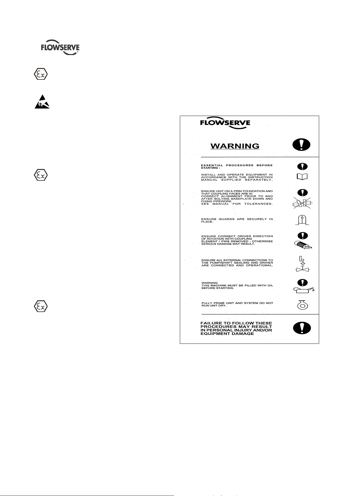
1.7.2 Safety labels
CORRECT MAINTENANCE IS REQUIRED TO
AVOID POTENTIAL HAZARDS WHICH GIVE A
RISK OF EXPLOSION
The responsibility for compliance with maintenance
instructions is with the plant operator.
To avoid potential explosion hazards during
maintenance, the tools, cleaning and painting
materials used must not give rise to sparking or
adversely affect the ambient conditions. Where there
is a risk from such tools or materials; maintenance
must be conducted in a safe area.
It is recommended that a maintenance plan and
schedule is adopted. (See section 6, Maintenance.)
Page 8 of 64
1.8 Specific machine performance
For performance parameters see section 1.5, Duty
conditions. Pump performance data are summarised
on pump data sheet which is included in proper
section of “Job User’s Instruct ion”.
1.9 Noise level
When pump noise level exceeds 85 dBA attention
must be given to prevailing Health and Safety
Legislation, to limit the exposure of plant operating
personnel to the noise. The usual approach is to
control exposure time to the noise or to enclose the
Page 9
HED/HED-DS USER INSTRUCTIONS ENGLISH 85392695 – 06/14
machine to reduce emitted sound. You may have
already specified a limiting noise level when the
equipment was ordered, however if no noise
requirements were defined then machines above a
certain power level will exceed 85 dBA. In such
situations consideration must be given to the fitting of
an acoustic enclosure to meet local regulations.
If a pump unit only has been purchased, for fitting
with your own driver, then the "pump only" noise
levels should be combined with the level for the driver
obtained from the supplier. If the m otor is driven by
an inverter, it may show an increase in noise level at
some speeds. Consult a Noise Specialist for the
combined calculation.
Pump noise level is dependent on a number of
factors - the type of motor fitted, the operating
conditions, pipework design and acoustic
characteristics of the building. The levels specified in
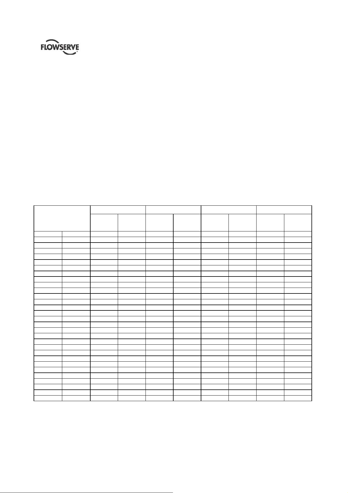
the table 1.1 are estimated and not guaranteed.
The dBA values are based on the noisiest ungeared
electric motors that are likely to be encountered.
They are Sound Pressure levels at 1 m (3.3 ft) from
the directly driven pump, for "free field over a
reflecting plane".
For units driven by equipment other than
electric motors or units contained within enclosures,
see the accompanying information sheets and
manuals.
Typical sound pressure level, dBA, L
Motor size
and speed
kW (hp)
<0.55 (<0.75) 72 72 64 65 62 64 62 64
0.75 (1) 72 72 64 66 62 64 62 64
1.1 (1.5) 74 74 66 67 64 64 62 63
1.5 (2) 74 74 66 71 64 64 62 63
2.2 (3) 75 76 68 72 65 66 63 64
3 (4) 75 76 70 73 65 66 63 64
4 (5) 75 76 71 73 65 66 63 64
5.5 (7.5) 76 77 72 75 66 67 64 65
7.5 (10) 76 77 72 75 66 67 64 65
11 (15) 80 81 76 78 70 71 68 69
15 (20) 80 81 76 78 70 71 68 69
18.5 (25) 81 81 77 78 71 71 69 71
22 (30) 81 81 77 79 71 71 69 71
30 (40) 83 83 79 81 73 73 71 73
37 (50) 83 83 79 81 73 73 71 73
45 (60) 86 86 82 84 76 76 74 76
55 (75) 86 86 82 84 76 76 74 76
75 (100) 87 87 83 85 77 77 75 77
90 (120) 87 88 83 85 77 78 75 78
110 (150) 89 90 85 87 79 80 77 80
132 (175) 89 90 85 87 79 80 77 80
150 (200) 89 90 85 87 79 80 77 80
160 (215) (1) (1) (1) (1) 83 84 81 83
200 (270) (1) (1) (1) (1) 85 87 83 85
300 (400) 87 90 85 86
315 (422) 87 90 85 86
355 (475) 87 90 86 87
500 (670) 88 (1) 86 (1)
1000 (1300) 90 (1) 88 (1)
1500 (2000) 90 (1) 90 (1)
(1) Noise levels of machines in this range should be based on actual equipment selected
For 1180 and 960 r/min reduce the 1450 r/min values by 2dBA
For 880 and 720 r/min reduce the 1450 r/min values by 3dBA
3500 rpm 2900 rpm 1750 rpm 1450 rpm
Pump
only
dBA
B
B at 1 m reference 20 μPa (LBwAB sound power 1pW where LB
pA
Pump &
motor
dBA
Pump
only
dBA
Pump &
motor
dBA
Pump
only
dBA
Pump &
motor
dBA
Pump
only
dBA
B >85 dBA)
pA
Pump &
motor
dBA
Page 9 of 64
Page 10
HED/HED-DS USER INSTRUCTIONS ENGLISH 85392695 – 06/14
2 TRANSPORT AND STORAGE
2.1 Consignment receipt and unpacking
Immediately after receipt of the equipment it must be
checked against the delivery and shipping documents
for its completeness and that there has been no
damage in transportation.
Any shortage and or damage must be reported
immediately to Flowserve and received in writing
within one month of receipt of the equipment. Later
claims cannot be accepted.
Check any crates, boxes and wrappings for any
accessories or spare parts which may be packed
separately with the equipment or attached to side
walls of the box or equipment.
Each product has a unique serial number. Check that
this number corresponds with that advised and
always quote this number in correspondence as well
as when ordering spare p a rts or further accessories.
2.2 Handling
2.2.1 General instructions concerning handling
Boxes, crates, pallets or cartons may be unloaded
using forklift vehicles or slings dependent on their
size and construction.
To lift machines or pieces with one or several
suspension rings, only use hooks and chains in
compliance with the local regulations concerning
safety. Never put cables, chains or ropes directly on
or in the suspension rings. Cables, chains or lifting
ropes must never present excessive bending.
Never bend the lifting hooks, suspension rings,
chains, etc., which should only be made to endure
stresses within, calculated limits. Remember that the
capacity of a lifting device decreases when the
direction of the lifting force direction makes an angle
with the device axis.
To increase the safety and the efficiency of the lifting
device, all the lifting elements must be as
perpendicular as possible. If necessary a lifting b eam
can be placed between the winch and the load.
When heavy pieces are lifted up, never stay or work
under the load or in the area, which could be in the
path of the load if it were to swing or fall away.
Never leave a load hanging from a winch. The
acceleration or the slowing-down of lifting equipment
must stay in the safety limits for the staff.
A winch must be positioned in such a way that the
load will be raised perpendicularly. Where possible
necessary precautions must be taken to avoid the
swing of the load, using for example two winches
making approximately the same angle, below 30°,
with the vertical.
2.3 Lifting
Make sure that any equipment used to
lift the pump or any of its components is capable of
supporting the weights encountered. Make sure that
all parts are correctly rigged before attempting to lift.
A crane must be used for all pump sets in
excess of 25 kg (55 lb). Fully trained personnel must
carry out lifting, in accordance with local regulations.
The driver and pump weights are recorded on
general arrangement drawing included into the job
user’s instruction.
2.3.1 To Lift unit
Pump, driver and baseplate can be lifted as a unit.
Sling from all four (4) eye bolts provided on baseplate
side rails. Failure to use all four (4) could result in
permanent distortion of the baseplate. Use as long a
sling as possible, or use a spreader arrangement.
Coupling bolting and spacer piece
must be removed from between pump and driver
half couplings before lifting baseplate with
pumping element.
To lift pump and baseplate, less driver, or
baseplate alone, sling from all four (4) eye bolts.
Do not lift pump, motor, base plate
unit by slinging from pump casing and/or eye bolt
on motor.
2.3.2 To lift driver
Refer to Manufacturers Instructions.
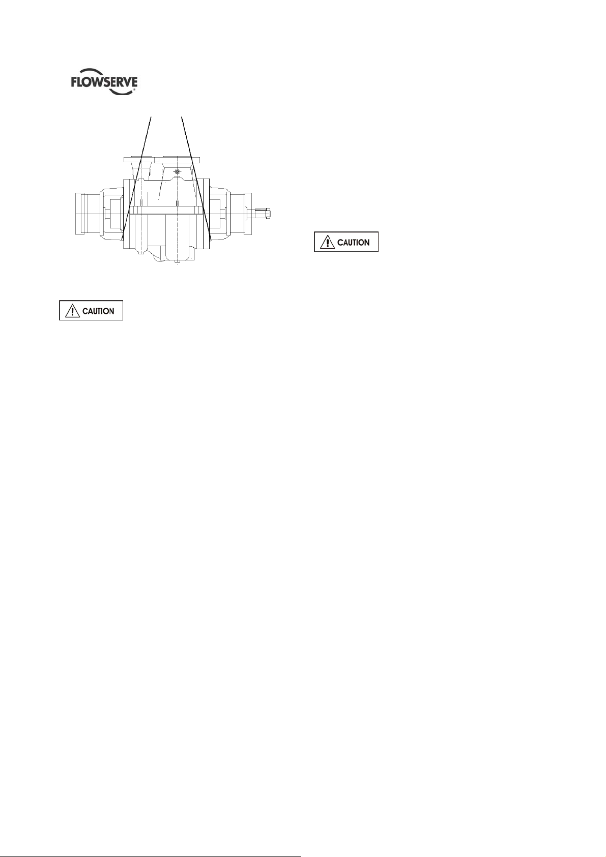
2.3.3 To lift complete pump only
Rig lifting straps at coupling end bearing bracket and
outboard bearing bracket. Make sure straps are
adjusted to obtain an even lift.
Page 10 of 64
Page 11
HED/HED-DS USER INSTRUCTIONS ENGLISH 85392695 – 06/14
2.4 Storage
Store the pump in a clean, dry location
away from vibration. Leave piping connection covers
in place to keep dirt and other foreign material out of
pump casing. Turn pump at intervals to prevent
brinelling of the bearings and the seal faces, if fitted,
from sticking.
Electric Motors (Pump Driver) should not be stored in
damp places without special protection (Refer to
Motor manufacturers instructions).
The pump may be stored as above for up to 6
months.
2.4.1 Long term storage
During extended periods of storage prior to
installation, precautions must be taken to protect the
pump from deterioration. The various parts of the
pump are protected prior to shipment by applying
varying grades of preservative to the parts. However,
during shipment and handling the preservatives are
subjected to conditions that can cause their removal.
Also, during extended periods of time the
preservatives may deteriorate. The listed procedures
(2.4.1.1 to 2.4.1.5) should be followed to prevent
deterioration of the pump during the extended
storage period. These procedures may also be
supplemented by the experience of the person(s)
performing the tasks.
2.4.1.1 Inspection upon arrival
When the pump is received it should be inspected for
damage or other signs of rough handling. If any
damage is found it should be reported to the carrier
immediately. Inspect the preservative coating on
various parts. If necessary, renew preservative in
areas where it has been rubbed or scraped.
Inspect all painted surfaces. If necessary, touch up
the areas where paint has been chipped or scraped.
Inspect all covers over pump openings and piping
connections. If covers or seals for the covers are
damaged or loose, they are to be removed, and a
visual inspection made of the accessible interior
areas for accumulation of foreign materials or water.
If necessary, clean and preserve the interior parts as
noted above to restore the parts to the "as sh ipped"
condition. Install or replace covers and fasten
securely.
2.4.1.2 Storage
If at all possible, the pump and its
component parts should be stored indoors where
they will be protected from the elements. In no case
should any pump element be subjected to extended
periods of submergence or wetting prior to start up. If
it is not possible to store the pump and its
components indoors, precautions must be taken to
protect them from the elements. Regardless of
whether storage is indoors or outside, the storage
area should be vibration free. All boxes marked for
indoor storage should be stored indoors. When
stored outdoors the pump and its components should
be protected from dirt, dust, rain, snow, or other
unfavourable conditions by heavy plastic sheets,
canvas, waterproof burlap or other suitable coverings.
All equipment must be placed upon skids or blocks to
prevent contact with the ground and surface
contaminants. Equipment must be adequately
supported to prevent distortion and bending.
The pump shaft should be rotated, in the direction of
rotation, at least 1 and 1/4 turns each week during
the storage period and any other periods of stand by.
When selecting a storage area the following should
be taken into
consideration.
a) The deterioration of the equipment will be
proportionate to the class of storag e pr ov ide d.
b) The expenses involved in restoring the
equipment at time of installation will be
proportionate to the class of storag e pr ov ide d.
2.4.1.3 Inspection and maintenance
The stored equipment has to be placed on a periodic
inspection schedule by the purchaser.
The responsibility for setting up an inspection
schedule rests with the purchaser and will be
dependent upon the class of storage provided. It
would be expected initially, inspection would occur
weekly, then depending upon the inspection reports
being favourable or unfavourable, inspection would
continue weekly, monthly, or quarterly, as may be
determined.
Page 11 of 64
Page 12

HED/HED-DS USER INSTRUCTIONS ENGLISH 85392695 – 06/14
Each inspection should consist of a general surface
inspection to assure that:
a) Pump supports are firmly in place.
b) Pump covers over openings are firmly in place.
c) Pump coverings, plastic or tarps are firmly in
place. Any holes or tears must be repaired to
prevent entrance of dirt or water.
d) Pump covers are periodically removed from
openings and interior accessible areas inspected.
If surface rusting has occurred, clean or coat with
preservative.
e) If rusting occurs on exterior surfaces clean and
repaint or coat with preservative.
f) Check individually wrapped parts for signs of
deterioration. If necessary, renew preservative
and wrapping.
Six months prior to the scheduled installation date, a
FLOWSERVE representative is to be employed to
conduct an inspection. This inspection may include,
not necessarily in its entirety and not limited to the
following:
a) An inspection of all periodic inspection r ecords as
kept on file by the purchaser, and all inspection
reports that have been compiled during the
storage period.
b) An inspection of the storage area to determine
the "as stored" condition of the equipment prior to
any protection covers being removed.
c) An inspection of the equipment with protective
covers and flange covers removed.
d) Depending upon the length of time the equipment
was stored, the type of storage provided (i.e.
Indoor: heated, unheated, ground floor, concrete
floor. Outdoors: under roof, no roof, waterproof
coverings, on concrete, on ground) and as a
result of the inspection of (a),( b) & (c) above the
FLOWSERVE representative may require a
partial or complete dismantling of the equipment.
e) Dismantling may necessitate restoration of
painted or preserved surfaces, and, or
replacement of gaskets, "O" rings, packing and
bearings.
f) All costs involved during inspection, dismantling,
restoration, replacement of parts and reassembly
will have to the accounted to the purchaser. All
necessary labour, tools and cranes will be
supplied by the purchaser.
Upon completion of the inspection the FLOWSERVE
representative shall submit a report to the purchaser,
and to the Manager of Customer Service, stating in
detail the results of the inspection.
One month prior to installation of the equipment, a
FLOWSERVE representative is to be employed to
conduct a final inspection.
This inspection will be made to assure that the
requirements of the six months inspection report were
satisfactorily completed and that the equipment is
ready for installation.
Upon completion of this inspection the FLOWSERVE
representative shall submit a final report to the
purchaser, and to the Manager of Customer Service,
advising the results of the final inspection.
All costs involved in conducting the final inspection
will have to the accounted to the purchaser.
Prior to and during start up, any requirements for the
services of an FLOWSERVE representative will
revert back to the original contract agreement for
equipment purchased, with revised costing.
2.4.1.4 Painting and preservation
Paints and preservatives used are either
FLOWSERVE standard or 'special' as required by the
contract specification. Refer to FLOWSERVE for the
description of paints and preservatives used on this
order if needed.
2.4.1.5 Associated equipment
Motors, Turbines, Gears, etc., being supplied by
FLOWSERVE.
Generally rotors of associated equipment should be
blocked to relieve bearing loads. Storage should be
indoors and dry. See the specific manufacturers
storage requirement s.
2.5 Recycling and end of product life
At the end of the service life of the product or its
parts, the relevant materials and parts should be
recycled or disposed of using an environmentally
acceptable method and local regulations. If the
product contains substances which are harmful to the
environment, these should be removed and disposed
of in accordance with current regulations. This also
includes the liquids and or gases in the "seal system"
or other utilities.
Make sure that hazardous substances o r
toxic fluids are disposed of safely and that the
correct personal protective equipment is used.
The safety specifications must be in accordance
with the current regulations at all times.
Page 12 of 64
Page 13

HED/HED-DS USER INSTRUCTIONS ENGLISH 85392695 – 06/14
3 PUMP DESCRIPTION
3.1 Configurations
HED pumps are horizontal two stage, radially split,
top/top flanged, between bearings centerline
mounted for heavy duty process services in full
compliance with API 610 standard. All sizes are
suitable for both 50 and 60 cycle operation. To
reduce NPSH requirements the HED can be fitted
with an inducer in front of the first impeller (HED-I) or
with a double suction first stage (HED-DS).
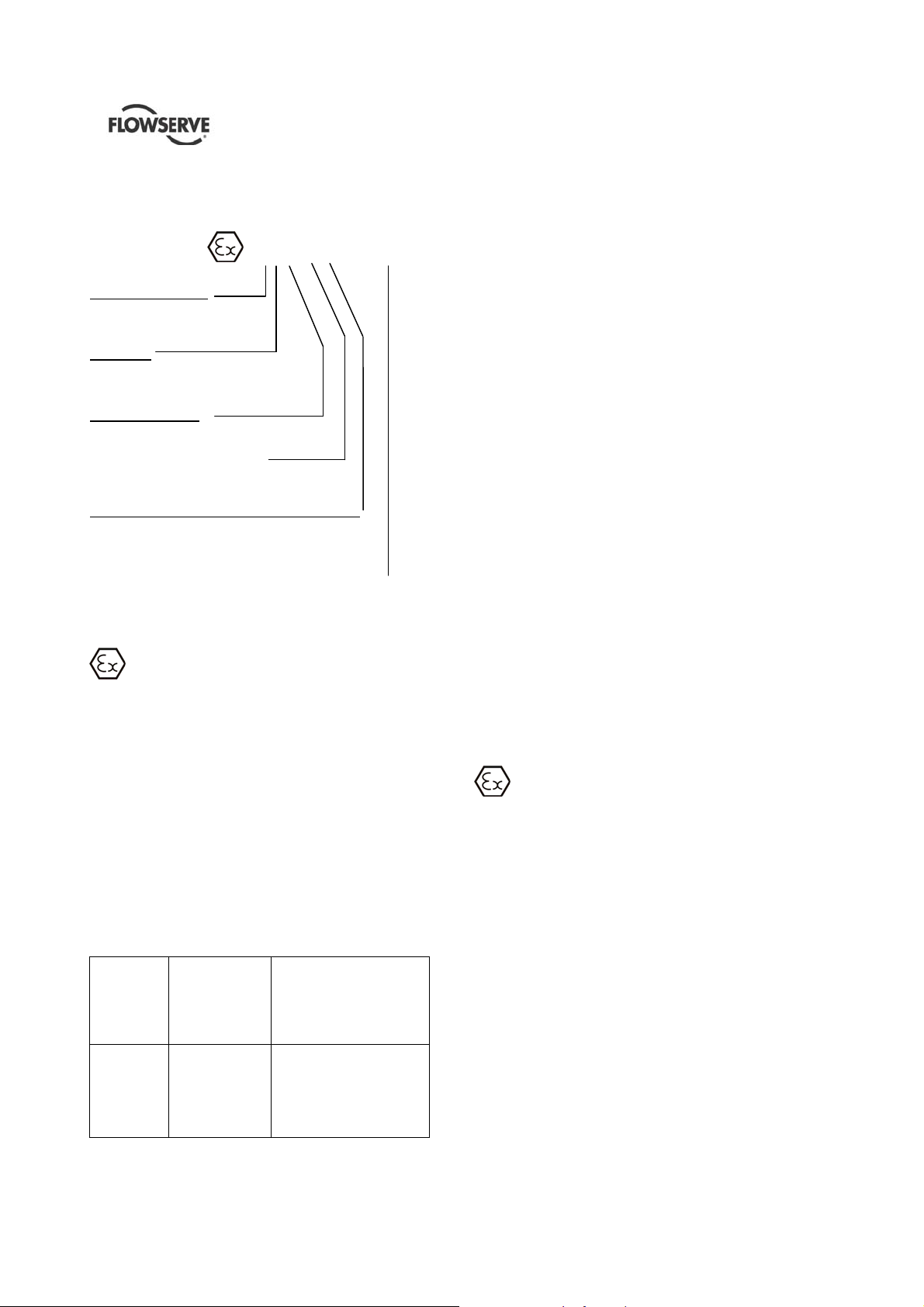
3.2 Nomenclature
The pump size will be engraved on the nameplate
typically as below:
6-HED-17-A
Nominal discharge branch size
Pump type
Nominal full size impeller diameter
Casing pattern type
The typical nomenclature above is the general guide
to the HED/HED-DS description. Identify the actual
pump size and serial number from the pump
nameplate. Check that this agrees with the applicable
certification provided.
3.3 Design of major parts
3.3.1 Pump casing
The casing is radially split with top suction and
discharge nozzles integrally cast.
This construction simplifies piping layout reducing
space requirements. Side/side or side/top
arrangements are available on request for particular
applications.
The mounting is centerline to retain alignment even at
elevated temperatures, permitting equal expansion in
all directions, and to give positive support to the
pump.
The first and second stage single volutes are
opposed to reduce hydraulic radial thrust and shaft
deflection, and the liquid is conveyed from the one to
the other by an integral cast crossover. The
interstage diaphragm too is integrally cast with the
casing. All the flow passages are accurately designed
to minimize efficiency losses.
3.3.2 Impeller
The standard impellers, single suction of the closed
type, are keyed to the shaft and secured by positive
locking devices. They are mounted face to face to
balance the hydraulic axial forces.
Impellers first and then the complete rotor are
dynamically balanced to avoid vibrations and assure
long trouble free life to seals and bearings.
Ceramic core castings are used to assure smooth
passages and the highest efficiency. Large eye areas
and low-entrance velocities give the pump very low
NPSH requirements, when extremely low NPSH
requirements are encountered, HED pumps can be
fitted with an inducer or with a double suction first
stage impeller.
Some pump sizes have more than one impeller
design, with differentiated B.E.P. capacities, for
maximum flexibility and operation with high
efficiencies throughout the coverage.
3.3.3 Wearing Rings
The casing and the impellers are fitted with
replaceable wear rings of hardened material. The
rings are held in place by a press fit with locking pins
on the casing and with threaded dowels on the
impellers.
3.3.4 Rotors
Rotors are of the stiff shaft design.
Shafts are of ample diameter, combined with the
minimum bearing span to minimize shaft deflectors
especially when the pump is operating at off peak
conditions.
Shafts are designed to meet API 610 deflection and
vibration requirements. Fully assembled rotors are
dynamically balanced can accommodate a wide
variety of single or dual seal arrangements as
standard.
3.3.5 Casing Covers
Two covers, one full size at the outboard pump end
which permits rotor removal and one reduced size
cover at inboard end provide circular type joints and
easy pump sealing with confined gaskets.
The metal to metal fit with confined controlled
compression gasket insures proper alignment
between casing and cover.
3.3.6 Bearing Housings
HED/HED-DS pumps are fitted as standard with
antifriction bearings. The radial bearing is a deep
groove type, while the thrust bearings are dual single
row angular contact type.
Lubrication is provided by an oil slinger in conjunction
with a TRICO constant level oiler, both provided as
standard. In case of particularly severe operating
conditions sleeve line with antifriction or tilting pad
thrust bearing are available with self-contained or
external lube system.
Page 13 of 64
Page 14

HED/HED-DS USER INSTRUCTIONS ENGLISH 85392695 – 06/14
Special bearing isolators (INPROSEAL or equivalent)
are available on request. Bearing housings can also
be adapted for optional oil mist or purge mist
lubrication systems.
3.3.7 Shaft seals
The mechanical seals, attached to the pump shaft,
seals the pumped liquid from the environment.
3.3.8 Driver
The driver is normally an electric motor. Different
drive configurations may be fitted such as internal
combustion engines, turbines, hydraulic motors etc
driving via couplings, belts, gearboxes etc.
3.3.9 Coupling/Coupling guards
Flexible spacer couplings are provided in various
makes and models to suit custome r preference.
(Aluminium non- hinged guards are provided).
3.3.10 Baseplate
Standard baseplates are welded steel, drain pan type
in conformance with API 610 standardized
dimensions. Horizontal driver alignment screws and
vertical baseplate leveling screws are provided when
required by API.
Special baseplates can be supplied to suit individual
installation circumstances.
3.3.11 Accessories
Accessories may be fitted when specified by the
customer.
Baseplates are fabricated and machined so to
guarantee the flatness and parallelism of pads as
required by API standard. The requirement is met by
supporting and clamping the baseplate at the
foundation bolt holes only.
3.4 Performance and operating limits
This product has been selected to meet the
specifications of your purchase order see section 1.5.
These pumps are furnished for a particular service
condition. Changes in the hydraulic system may
affect the pump's performance adversely.
This is especially true if the changes reduce the
pressure at the suction flange or if the liquid
temperature is increased. In case of doubt, contact
the nearest FLOWSERVE office.
3.4.1 Effect of specific gravity
Pump capacity and total head in meters (feet) do not
change with SG, however pressure displayed on a
pressure gauge is directly proportional to SG. Power
absorbed is also directly proportional to SG. It is
therefore important to check that any change in SG
will not overload the pump driver or over-pressurize
the pump.
3.4.2 Effects of viscosity
The pump is designed to deliver rated capacity and
rated head for a liquid with a particular viscosity.
For a given flow rate the total head reduces with
increased viscosity and increases with reduced
viscosity. Also for a given flow rate the power
absorbed increases with increased viscosity, and
reduces with reduced viscosity.
When contemplating operation at some viscosity
other than the one for which the pump was originally
designed and/or applied, the changed conditions
should be referred to FLOWSERVE for
recommendations.
When pump is handling heavy
viscous liquid, the temperature of the liquid must
allow it to be pumped easily. Liquid may have to
be heated prior to pump start-up.
3.4.3 Changing the pump speed
Changing pump speed effects flow, total head, power
absorbed, NPSH
, noise and vibration. Flow varies in
R
direct proportion to pump speed. Head varies as
speed ratio squared. Power varies as speed ratio
cubed. If increasing speed it is important therefore to
ensure the maximum pump working pressure is not
exceeded, the driver is not overloaded,
NPSH
>NPSHR, and that noise and vibration are
A
within local requirements and regulations.
3.4.4 Net Positive Suction Head (NPSH)
Any liquid, hot or cold, must be pushed into the
impeller of the pump by absolute pressure, such as
the atmospheric or vessel pressure from which the
pump takes its suction.
The head in feet of liquid necessary to push the
required flow into the pump is called Net Positive
Suction Head. This value, more commonly called
NPSH, is measured above the vapour pressure of the
liquid at the pumping temperature.
There are two kinds of NPSH: the NPSH
is the head
R
required by the pump to cover the losses in the pump
suction - that is shown on the pump characteristic
curve.
The second, NPSH
, is the head available in the
A
system, taking into account friction loss in suction
piping, valves, fittings etc. In all cases the NPSH
,
A
measured above vapour pressure, must exceed the
NPSH
in order to push the liquid into the pump.
R
Failure to have this will result in both bad
performance and mechanical damage to the pump,
and in certain cases actual pump failure.
Page 14 of 64
Page 15

HED/HED-DS USER INSTRUCTIONS ENGLISH 85392695 – 06/14
If any change in NPSHA is proposed, ensure its
margin over NPSH
to the pump performance curve to determine exact
requirements particularly if flow has changed. If in
doubt please consult your nearest Flowserve office
for advice and details of the minimum allowable
margin for your application.
3.4.5 Minimum Continuous Stable Flow
The Minimum Continuous Stable Flow for the pump is
stated on the Data sheet.
3.4.6 Minimum flow control
In all cases, it is the customer's responsibility to
supply a system and/or control which assures that
any pump within a system is not operated below its
minimum flow condition.
In many cases, this is not a problem because the
system is operating within its own flow range to
assure product delivery. A simple high pressure
alarm, shut down and/or bypass control can be used .
However, in systems where product demand has high
swings or where more than 100% capacity units are
desired to support a product system, additional care
must be taken.
3.4.7 Thermal control
A thermal control of the unit can be provided by
thermal sensors which read direct or "related to" fluid
temperatures and respond accordingly by opening
additional flow paths until the given unit reestablishes the acceptable temperature rise, and sets
off alarms if not achieved within reasonable/normal
time periods. (High limit could actually shut down
unit).
3.4.8 Pressure and/or Flow Control
Pressure and/or flow sensors can be used to hold the
unit at higher flows by opening additional flow paths
once a "high pressure limit" or " low flow limit" was
indicated.
Upon system reaching increased flow a "low pressure
limit" or "high flow limit" setting would close the
bypass flow path. Care must be taken to allow for
signal spread to avoid cyclic conditions.
3.4.9 Operating at Reduced Capacity
prolonged operations at capacities less than MCSF
as stated in Data Sheet.
is not significantly eroded. Refer
R
Damage to pump may result from
4 INSTALLATION
Equipment operated in hazardous locations
must comply with the relevant explosion protection
regulations. See section 1.6.4, Products used in
potentially explosive atmospheres.
4.1 Location
The pump should always be located as near as
possible to the suction supply.
Install the unit close to the source of the liquid to be
pumped. It is desired to simplify the suction and
discharge piping layout. When selecting the location,
be sure to allow adequate space for operation as well
as for maintenance operations involving dismantling
and inspections of parts.
Head room is an important consideration as an
overhead lift of some type is required
4.2 Part assemblies
Motors may be supplied loose. It is the responsibility
of the installer to ensure that the motor is assembled
to the pump and lined up as detailed in section 4.5.2.
Prior to grouting, an initial alignment
check in accordance with the alignment section of
this document shall be performed to verify that
coupling spacing and final alignment can be achieved
without modifying the hold down bolts or the machine
feet. This is necessary to ensure that the baseplate
was not damaged during the transportation.
4.3 Foundation
There are many methods of installing
pump units to their foundations. The correct method
depends on the size of the pump unit, its location and
noise vibration limitations. Non-compliance with the
provision of correct foundation and installation may
lead to failure of the pump and, as such, would be
outside the terms of the warranty.
The foundation should be sufficiently rigid and
substantial to prevent any pump vibration and to
permanently support the baseplate at all points.
The most satisfactory foundations are made of
reinforced concrete. These should be poured well in
advance of the installation to allow sufficient time for
drying and curing.
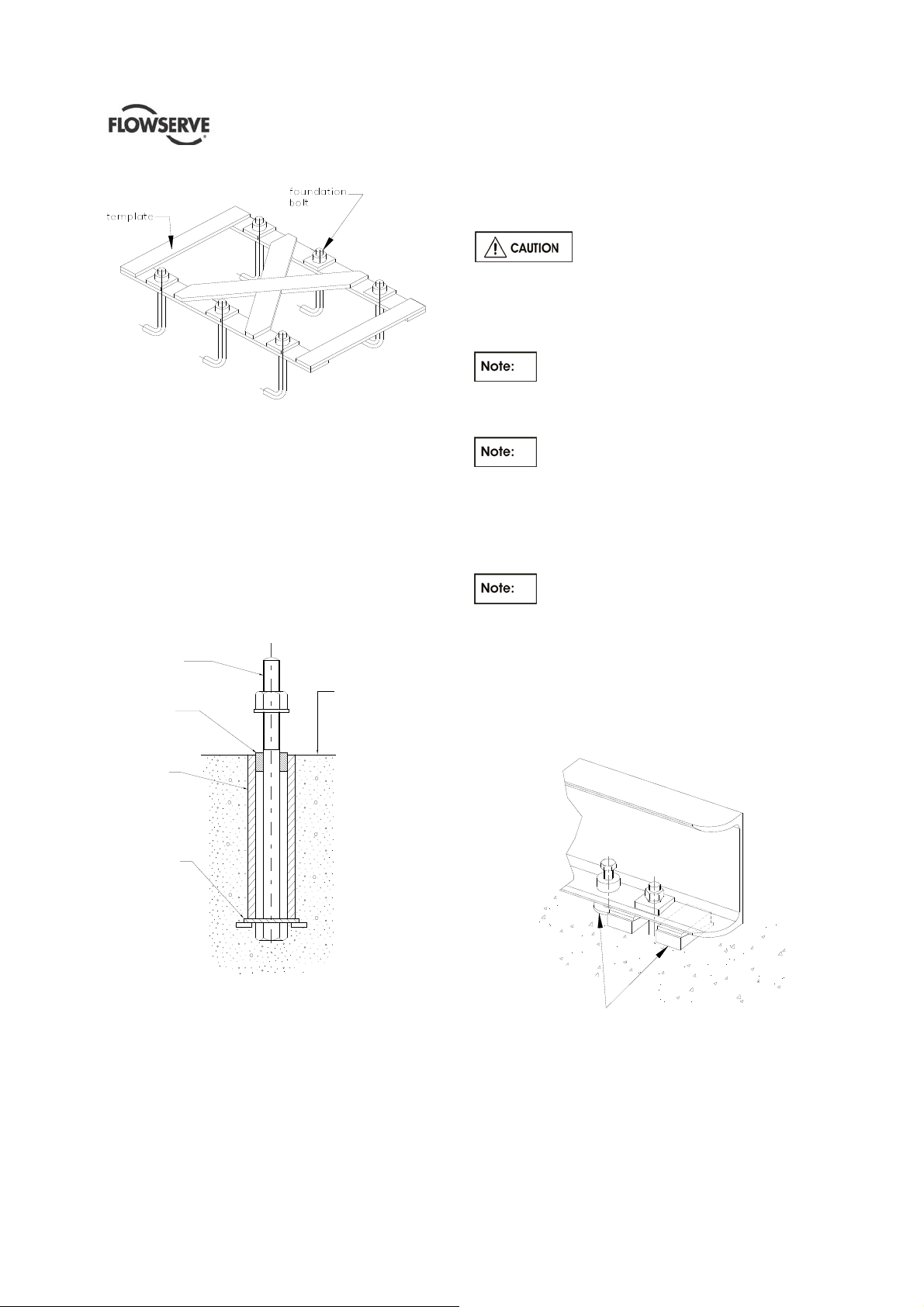
The General Arrangement Drawing (In Job’s User
Instruction) will furnish overall outline of pump
baseplate, anchor bolt locations, size of bolts, etc in
order to provide proper shape to the primary
concrete. Anchor bolts can be positioned or by a
special template (not supplied by FLOWSERVE see
figure 4.1) or by the baseplate itself if proper pockets
have been provided in primary concrete.
Page 15 of 64
Page 16
HED/HED-DS USER INSTRUCTIONS ENGLISH 85392695 – 06/14
Template for Hanging Foundation Bolts
Figure 4.1
Figure 4.2 below illustrates an alternative foundation
bolt arrangement which can be used in lieu of
standard foundation bolts. Notice the large washer
with lugs at the bottom. It should be welded to the
bolt and pipe sleeve to prevent turning. Allow a little
more than the specified threaded bolt length above
the rail of the baseplate. The excess can always be
cut off if it is not needed. A rough finish top surface is
best when applying grout.
ALLOW AMPLE THREADED
BOLT LENGTH ABOVE
ROUGH CONCRETE
ROUGH FINISH
STUFF WASTE AROUND
BOLT WHILE POURING
CONCRETE
FOR GROUT
In case of installation over a steel structure (platform)
ensure that the top of the steel structure is cleaned
and degreased.
In order to obtain the parallelism and
flatness of pads required by API standard, baseplate
has to be properly levelled by levelling screws
provided on it and clamping the baseplate at the
foundation bolts only (For proper detailed procedure
refer to Chapter 5 para 3.9.4 of API RP 686 ).
Coupling bolting and spacer piece must
be removed from between the pump and driver half
couplings before lifting baseplate with pumping
element.
When the unit is mounted directly on
structural steel framing, it should be located directly
over as near as possible to the main building
members, beams, or walls. A soleplate should be
bolted or welded to the steel frame to guara ntee the
proper surface.
When lifting baseplate with pumping
element, sling baseplate from all lifting lugs provided.
Refer to Section 2.3.1
Prepare sufficient steel plates to be placed below
each baseplate jacking screw furnished with the
baseplate. The purpose of the plate is to spread the
load of the screw without crushing the concrete
below.
PIPE SLEEVE TO BE
THREE TIMES DIAMETER
OF ANCHOR BOLT
WELD A LARGE WASHER
WITH LUGS TO THE
BOTTOM OF BOLT
AND PIPE SLEEVE TO
PREVENT TURNING
Figure 4.2
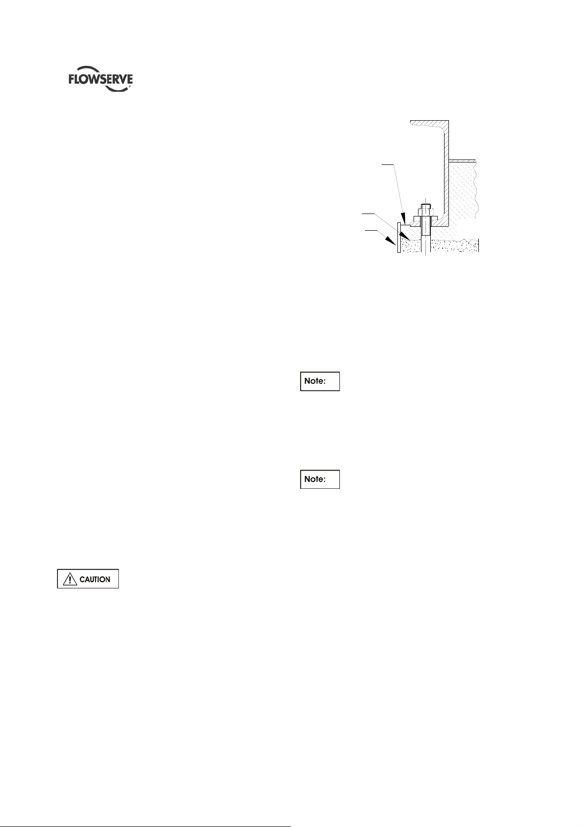
4.3.1 Baseplate levelling
Before putting the unit on the foundation, thoroughly
clean the top of the foundation. Break off any loose
pieces of cement and roughen the top with a chisel to
afford a good hold for grout.
Page 16 of 64
Not supplied
Figure 4.3
4.3.2 Method of levelling baseplate using wedges
or shims
a) Level the baseplate by using a machinist's level
on the machined surfaces of the pump and driver
Page 17
HED/HED-DS USER INSTRUCTIONS ENGLISH 85392695 – 06/14
pads. Levelling is best achieved by adjusting the
shim pack thickness under each holding bolt.
Carefully raise the baseplate by using eith er the
baseplate jacking screws provided or by levering
with a suitable pinch bar or by installing a low
level hydraulic jack.
b) Adjust the shim pack thickness and lower the
baseplate.
c) Repeat this procedure in a logical manner at
each bolt position until the baseplate is both
straight and levelled. A degree of 0.25 mm per
metre (0.0035 inch per foot) length is achievable
on most units with a maximum of 0.40 mm per
meter length (0.005 inch per foot).
d) In case of installation on steel structures (like
platforms) proceed with these extra steps:
Using a calibrated pin with a cone p oint mark
the centre of baseplate support pads
mounting holes on the soleplate.
Lift and move away the pump skid.
Drill and tap the soleplate fixing holes.
Replace the pump skid so that the soleplate
fixing holes align with the baseplate support
pads mounting holes.
Level the unit like done previously (see points
a, b, c).
e) When the baseplate is level, pull down the
foundation bolts so they are snug or tighten the
fixing bolts in case of installation on steel
structure. This may have disturbed the baseplate,
so re-check the levels.
Ensure that shaft alignment per Section 4.5 can be
achieved prior to grouting the baseplate.
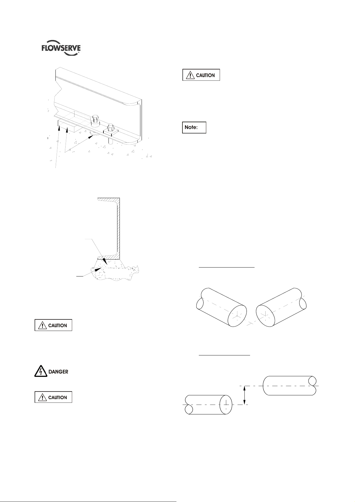
4.4 Grouting
Build a dam around the foundation as shown in
Figure 4.4 after levelling the baseplate. It is a matter
of personal preference whether the levelling wedges
under the baseplate should be removed after
grouting. If you do not want to remove the wedges,
carefully mark their locations before pouring grout.
Before grouting, level machined
pads of baseplate in both directions and perform
a rough shaft/coupling alignment. Alignment after
grout has set will not be possible if above is not
satisfactorily completed.
4.4.1 Fully Grouted Baseplates
FINISHED GROUT
LEAVE TOP OF
FOUNDATION ROUGH
DO NOT FINISH
WITH TROWEL
DAM
Figure 4.4
GROUTING 1 TO 2
INCHES DEEP
CONCRETE
Use a good, high strength, non shrink grout mix and
install as per manufacturer's instructions.
Holes are provided in the baseplate to permit pouring
the grout and stirring while acting as air vents. Fill
under the baseplate completely, stirring to assure
correct distribution of the grout. Check to see that the
grout flows under the edges of the base plat e even ly.
Do not vibrate baseplate when grouting,
making sure baseplate is vented correctly and all
areas are thoroughly puddle to preven t any resonant
problems.
When the grout is thoroughly hardened, remove the
dam and wedges, if desired, filling in the holes they
leave with grout.
Pour grout until level reaches top of dam.
Allow to dry sufficiently to prevent grout from
overflowing while completing the remaining grouting.
4.4.2 Baseplate not Intended for Grouting but
Installed on Concrete Foundations
According to the figure 4.3.1 and 4.4.1 the baseplate
will not be grouted but only a sealing shall be
provided. During the preparation, as indicated on the
General Arrangement drawing a certain number of
openings into the sealing must be guaranteed. After
the sealing the blocks used to realise the openings
must be removed. Blocks have to be wider than the
baseplate longitudinal beam in order to guarantee the
opening for the drainage.
Page 17 of 64
Page 18
Not supplied
BLOCK TO BE REMOVED
AFTER THE SEALING
Figure 4.5
SEALING
TOP OF FOUNDATION
Figure 4.6
4.5 Initial alignment
4.5.1 Thermal expansion
PRIMARY
CONCRETE
HED/HED-DS USER INSTRUCTIONS ENGLISH 85392695 – 06/14
4.5.2.1 Shaft/Coupling alignment
Shaft alignment must be correct for
successful operation. Rapid wear, noise, vibration
and actual damage to the equipment may be
caused by shaft misalignment. The shafts must
be aligned within the limits given within this
section.
Adjustment to correct the alignment in one
direction may alter the alignment in another direction.
Always check in all directions after making any
adjustment.
Coupled equipment must be aligned to minimise
unnecessary stresses in shafts, bearings and
coupling. Flexible couplings will not compensate for
appreciable misalignment. Foundation settling,
thermal expansion or nozzle loads resulting in
baseplate/foundation deflection and vibration during
operation may require the full coupling misalignment
capability.
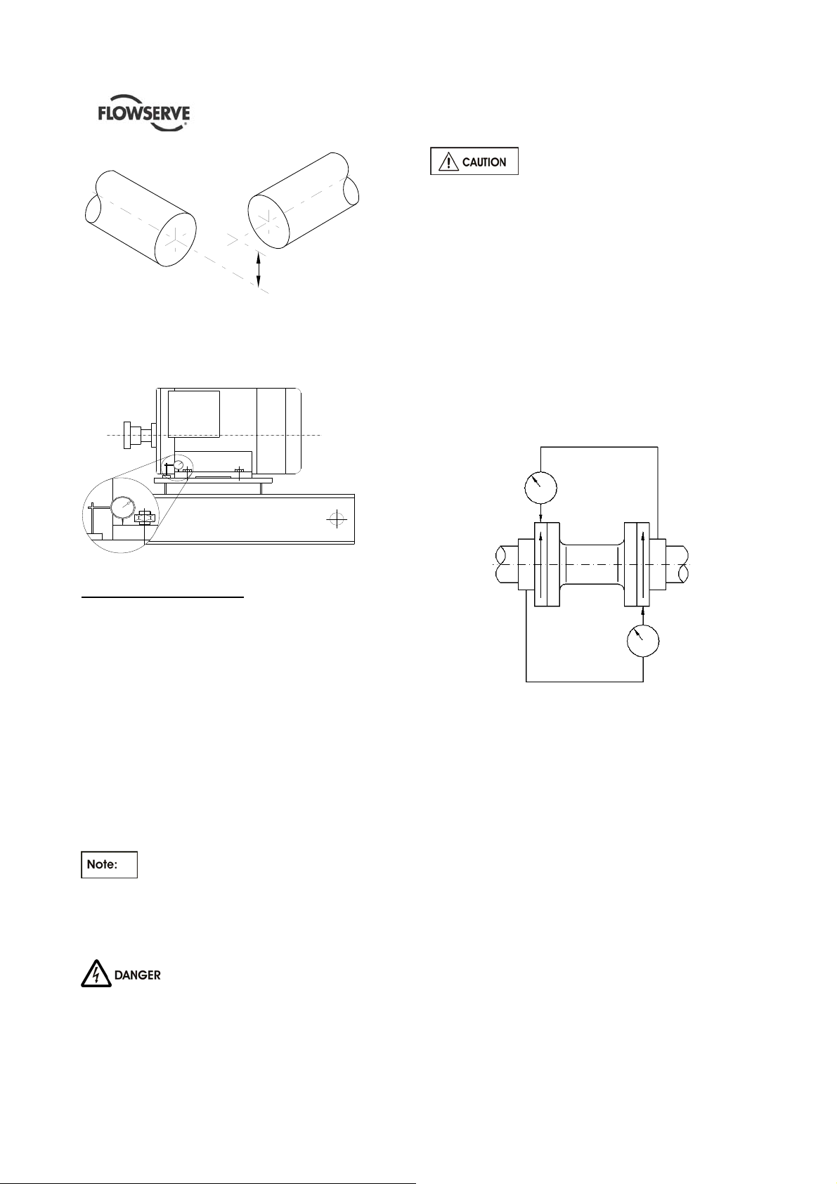
4.5.2.1.1 Types of misalignment
There are two types of shaft misalignment: angular
and offset. Therefore, two sets of measurements and
corrections are required. Both types of misalignment
can occur in horizontal and vertical planes and are
present in most applications.
A) Angular misalignment
In angular misalignment, the centre line of the shafts
intersects, but are not on the same axis.
The pump and motor will normally
have to be aligned at ambient temperature and
should be corrected to allow for thermal expansion at
operating temperature.
4.5.2 Alignment methods
Ensure pump and driver are isolated
electrically and the half couplings are disconnected
The alignment MUST be checked.
Although the pump will have been aligned at the
factory it is most likely that this alignment will have
been disturbed during transportation or handling. If
necessary, align the motor to the pump, not the pump
to the motor.
Page 18 of 64
Figure 4.7
B) Offset misalignment
In offset misalignment, the shaft centre lines are
parallel but do not intersect.
Figure 4.8 – offset misalignment
Page 19
HED/HED-DS USER INSTRUCTIONS ENGLISH 85392695 – 06/14
Figure 4.9 – combination of offset and angular misalignment
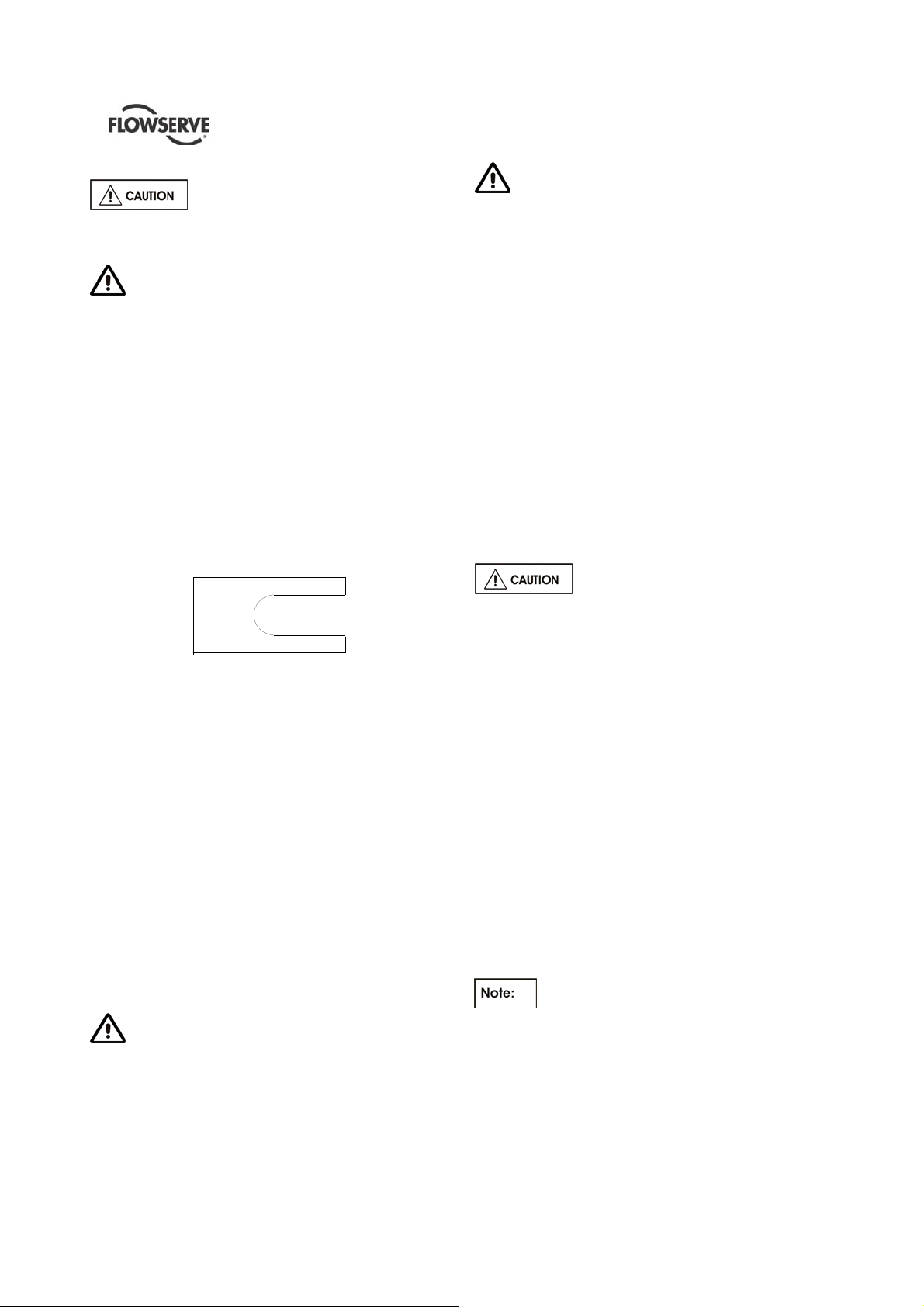
4.5.2.2 Alignment using the reverse dial Indicator
The following practices are recommended when
using the reverse method of alignment. These should
be carried out prior to main alignment.
The alignment MUST be checked.
Although the pump will have been aligned at the
factory it is most likely that this alignment will have
been disturbed during transportation or handling. If
necessary, align the motor to the pump, not the pump
to the motor.
The alignment is achieved by adding or removing
shims under the motor feet and also moving the
motor horizontally as required. In some cases where
the alignment cannot be achieved it will be necessary
to move the pump before recommencing the above
procedure.
For couplings with narrow flanges use a dial in dicator
as shown on figure 4.11 to check both parallel and
angular alignment.
For detailed alignment procedure refer to API RP686.
Figure 4.10
CHECK FOR SOFT FOOT
This is a check to ensure that there is no undue
stress on the driver holding down bolts; owing to nonlevel baseplate or twisting. To check, remove all
shims and clean surfaces and tighten down driver to
the baseplate. Set a dial indicator as shown in sketch
and loosen off the holding down bolt while noting any
deflection reading on the Dial Test Indicator - a
maximum of 0.05 mm (0.002 in.) is considered
acceptable but any more will have to be corrected by
adding shims, for example, if the Dial Test Indicator
shows the foot lifting 0.15 mm (0.006 in.) then this is
the thickness of shim to be placed under that foot.
Tighten down and repeat the same procedure on all
other feet until all are within tolerance.
If the driver is an electric motor with sleeve
bearings then the magnetic centre at which the rotor
will run must be set. This is usually done by lining up
a groove in the shaft to a pointer fixed to the motor
body (refer to Motor Manufacture’s instructions).
Ensure pump and driver are isolated
electrically and the half couplings are disconnected.
Figure 4.11
Maximum permissible misalignment at working
temperature:
Parallel 0.05 mm (0.002 in.) TIR
Angular 0.05mm/100mm (0.0005In/In)
Pumps with thick flanged non-spacer couplings can
be aligned by using a straight-edge across the
outside diameters of the coupling hubs and
measuring the gap between the machined faces
using feeler gauges, measuring wedge or calipers.
When the electric motor 4has sleeve bearings it is
necessary to ensure that the motor is aligned to run
on its magnetic centreline.
Refer to the motor manual for details.
A button (screwed into one of the shaft ends) is
normally fitted between the motor and pump shaft
ends to fix the axial position.
Page 19 of 64
Page 20
HED/HED-DS USER INSTRUCTIONS ENGLISH 85392695 – 06/14
If the motor does not run in its
magnetic centre the resultant additional axial force
may overload the pump thrust bearing.
Complete piping as below and see sections 4.7,
“Final shaft alignment check” up to and including
section 5, “Commissioning, start-up, operation and
shutdown” before connecting driver and checking
actual rotation.
4.5.3 Shims
The shims between the equipment feet and mounting
surface should be clean and dry. This is especially
critical for pumps in service for sometime and need to
be realigned. Water, dirt and rust may change the
height of the shim pack over a period of time. Shim s
should be made large enough to support the weight
of the equipment on its mounting foot. Do not use
many thin shims as this may result in a spongy
mounting.
Figure 4.12
Recommended shim design
Move the equipment vertically by adding or removing
the calculated thickness of shims. Torque holding
down bolts to required values.
4.5.4 Hot alignment – Pump and driver dowels
Pump hold down bolts are to be torqued down and
dowel pins are to be located in pump feet. (This is
only applicable if Hot Alignment is required).
Refer to driver outline drawing and/or driver
instructions for driver doweling information.
A hot check can only be made after the unit has been
in operation a sufficient length of time to assume its
NORMAL operating temperature and conditions. If
the unit has been correctly cold set, the offset
misalignment will be within within the limits stated on
par 4.5.2.2 when in operation.
If not make adjustments.
Do not attempt any maintenance,
inspection, repair or cleaning in the vicinity of
rotating equipment. Such action could result in
injury to operating personnel.
Before attempting any inspection or repair
on the pump the driver controls must be in the
"off" position, locked and tagged to prevent
restarting equipment and injury to personnel
performing service on the pump.
4.5.5 Assemble coupling
a) Assemble coupling as per the manufacturer's
instructions included in Appendix of this manual.
b) Install coupling guard
4.5.6 Installation check list
a) Level Baseplate?
b) Grout Baseplate - Check Foundation Bolts?
c) Alignment Shaft/Coupling?
d) Piping Installed - Correct Vent, Gauge, Valve,
Suction Strainer Locations?
e) All Flange Bolting Correctly Torqued with
appropriate gaskets in place?
f) Check Shaft/Coupling Alignment again.
g) Coupling guard correctly installed ?
4.6 Piping
Never use the pump as a support for
piping.
4.6.1 General
These units are furnished for a particular service
condition. Changes in the hydraulic system may
affect performance adversely. This is especially true if
the changes reduce the pressure at the suction or if
the liquid temperature is increased. In case of doubt
contact FLOWSERVE.
Suction and discharge piping should be of ample
size, be installed in direct runs, and have a min imum
of bends. Double bends must be avoided in suction
line and a straight run of pipe, equal 7 to 10 times the
pipe diameter is desired directly upstream of the
suction nozzle.
In order to minimize friction losses and hydraulic
noise in the pipework it is good practice to choose
pipework that is one or two sizes larger than the
pump suction and discharge. Typically main pipework
velocities should not exceed 2 m/s (6 ft/sec) suction
and 3 m/s (9 ft/sec) on the discharge.
Provision must be made to support piping
external to the pump to prevent excessive nozzle
loads, maintain pump/driver alignment and avoid pipe
induced vibrations.
Take into account the available NPSH which must be
higher than the required NPSH of the pump.
Page 20 of 64
Page 21

HED/HED-DS USER INSTRUCTIONS ENGLISH 85392695 – 06/14
Maximum forces and moments allowed on the pump
flanges vary with the pump size and type. To
minimize these forces and moments that may, if
excessive, cause misalignment, hot bearings, worn
couplings, vibration and the possible failure of the
pump casing, the following points should be strictly
followed:
Prevent excessive external pipe load.
Never draw piping into place by applying force to
pump flange connections.
Do not mount expansion joints so that their force,
due to internal pressure, acts on the pump flange.
Ensure piping and fittings are flushed
before use.
Ensure piping for hazardous liquids is arranged
to allow pump flushing before removal of the pump.
4.6.2 Suction Piping
a) The inlet pipe should be one or two sizes larg er
than the pump inlet bore and pipe bends should
be as large radius as possible.
b) Keep the suction pipe free of all air pockets.
(Vent is required).
c) Pipework reducers should have a maximum tota l
angle of divergence of 15 degrees.
d) Use only eccentric reducers with the straight side
on the top.
e) Flo w should enter the pump suction with uniform
flow, to minimize noise and wear.
f) A gate valve is recommended in the suction line.
g) Except if considerable foreign matter is expected
strainers are not recommended in inlet piping.
Inlet strainers, when used, should have a net
“free area” (see section 4.6.2.1)
4.6.2.1 Suction Strainer
It is recommended that a temporary strainer be
placed in the suction pipe to prevent lodging of
foreign material in the impeller. A pipe spool of
sufficient size should be provided with gauge taps to
accommodate the suction strainer.
The strainer should be installed as close to the pump
as possible. The open area of the strainer should
have a minimum of a 3 to 1 ratio to the area of the
pump inlet.
Pressure gauges should be installed on both sides of
the strainer, so the pressure drop across the strain er
can be measured when the unit is operated.
Typical temporary suction strainer
Pressure gauges should be installed on both sides of
the screen so that the pressure drop across the
screen can be measured.
When the unit is being started, the gauges on each
side of the screen should be carefully watched. An
increase in the differential pressure between the two
gauges indicates that the screen is becoming clogged
with dirt and scale. At this point, the pump should be
shut down, and the screen cleaned and/or replaced.
A spool piece should be installed in
suction line so that the suction strainer may be
installed and removed with a pressure gauge
between the strainer and pump.
4.6.2.2 Bypass Line
Operation at low flows results in
pump horsepower heating the liquid. A bypass
may be required to prevent vaporization and
subsequent pump damage. Refer to local
FLOWSERVE branch to determine if a bypass is
required. Mechanical damage may result from
continuous operation at flows less than specified.
4.6.3 Discharge piping
a) Install a check valve and a gate valve in the
discharge pipe of the pump. When the pump is
stopped, the check valve will protect the pump
against excessive pressure and will prevent the
pump from running backward. The check valve
should be installed between the gate valve and
the pump nozzle in order to permit its inspection.
Never throttle pump on suction side and never
place a valve directly on the pump inlet nozzle.
b) Pipe work reducers should have a maximum total
angle of divergence of 15 degrees.
4.6.4 Drains and Vents
Pipe pump casing drains and vent to a convenient
disposal point.
Jacket piping
The stuffing boxes are jacketed for water cooling and
also the bearing brackets can be jacketed. They
Page 21 of 64
Page 22

HED/HED-DS USER INSTRUCTIONS ENGLISH 85392695 – 06/14
should be provided with cooling only if required by the
operating conditions
4.6.5 Pumps fitted with mechanical seals
Single seals requiring re-circulation will normally be
provided with auxiliary piping from pump casing
already fitted. Symbols which FLOWSERVE work on
seal connections are as follows:
Q - quench
F - flush
D - drain outlet
BI - barrier fluid in
BO - barrier fluid out
Single seals which require external flushing or
auxiliary quench must be connected to a specific
supply.
Double seals require a barrier liquid compatible with
the pumped liquid.
With back-to-back double seals, the barrier liquid
should be at a minimum pressure of 2 bar above the
maximum pressure on the pump side of the inner
seal. The barrier liquid pressure must not exceed
limitations of the seal on the atmospheric side. For
toxic service the barrier liquid supply and discharge
must be in a safe area.
For specific information refer to the mechanical seals
manufacturer’s instructions.
4.6.6 Final checks
Check the tightness of all bolts in the suction and
discharge pipework. Check also the tightness of all
foundation bolts and auxiliary lines.
4.7 Final shaft alignment check
After connecting piping to the pump, rotate the shaft
several times by hand to ensure there is no binding
and all parts are free.
Recheck the coupling alignment, as previously
described, to ensure no strain on coupling is due to
pipe. If pipe strain exists, correct piping.
4.8 Electrical connections
Electrical connections must be made by
a qualified Electrician in accordance with relevant
local national and international regulations.
It is important to be aware of the EUROPEAN
DIRECTIVE on potentially explosive areas where
compliance with IEC60079-14 is an additional
requirement for making electrical connections.
It is important to be aware of the EUROPEAN
DIRECTIVE on electromagnetic compatibility when
wiring up and installing equipment on site. Attention
must be paid to ensure that the techniques used
during wiring/installation do not increase
electromagnetic emissions or decrease the
electromagnetic immunity of the equipment, wiring or
any connected devices. If in any doubt contact
Flowserve for advice.
The motor must be wired up in
accordance with the motor manufacturer's
instructions (normally supplied within the terminal
box) including any temperature, earth leakage,
current and other protective devices as appropriate.
The identification nameplate should be checked to
ensure the power supply is appropriate.
A device to provide emergency stopping must
be fitted.
If not supplied pre-wired to the pump unit, the
controller/starter electrical details will also be supplied
within the controller/starter.
For electrical details on pump sets with controllers
see the separate wiring diagram.
See section 5.3, Direction of rotation
before connecting the motor to the electrical supply
4.9 Protection systems
The following protection systems are
recommended particularly if the pump is installed in a
potentially explosive area or is handling a hazardous
liquid. If in doubt consult Flowserve.
If there is any possibility of the system allowing the
pump to run against a closed valve or below
minimum continuous safe flow a protection device
should be installed to ensure the temperature of the
liquid does not rise to an unsafe level.
If there are any circumstances in which the system
can allow the pump to run dry, or start up empty, a
power monitor should be fitted to stop the pump or
prevent it from being started. This is particularly
relevant if the pump is handling a flammable liquid.
If leakage of product from the pump or its associated
sealing system can cause a hazard it is
recommended that an appropriate leakage detection
system is installed.
To prevent excessive surface temperatures at
bearings it is recommended that temperature or
vibration monitoring are carried out. See sections
5.7.4 and 5.7.5.
Page 22 of 64
Page 23

HED/HED-DS USER INSTRUCTIONS ENGLISH 85392695 – 06/14
5 COMMISSIONING, START-UP,
OPERATION AND SHUTDOWN
The following procedures are presented to outline the
most important steps involved in pump operation. Any
modification of these procedures due to particular
installation peculiarities should conform to good
engineering practices.
Never operate the pump with suction
valve closed.
Never operate the pump unless it is filled with liquid
and vented.
Never operate the pump unless a liquid source is
available.
Never operate the pump with discharge valve closed
or below the minimum specified flow rate. If reduced
capacity operation is required on occasion, a
recirculating line should be installed according
FLOWSERVE recommendations.
Where possible avoid severe thermal shocks due to
sudden changes of liquid temperature. Warm-up the
pump at all times before start-up if the pumped liquid
is hot or subject to crystallize
Lubricate the unit prior to starting.
Do not operate the unit unless coupling guards are
bolted in place.
Never operate the pump above the name plate
conditions.
During pump operation, keep the vent and drain
valves in closed position, to prevent any liquid from a
high pressure point flowing into a low pressure point.
Do not wipe down in the vicinity of rotating parts. If
unusual noise or high vibrations occur, secure the
pump as soon as possible.
5.1 Pre-commissioning procedure
The following steps should be followed at initial start
up and after the equipment has been overhauled:
a) Prior to installing the pump, flush the suction side
of the system to remove all deposit (slag, bolts
etc).
b) Ensure the pump and piping is clean. Before
putting the pump into operation, the piping should
be thoroughly back flushed to remove any foreign
matter which may have accumulated during
installation. Take all possible care not to
contaminate your system.
c) Install suction strainer if required. (See Section
4.6.2.1).
d) Fill the bearing housings with the appropriate oil
to the correct level. Bearing must receive a small
amount of oil prior to startin g to ensure adequa te
lubrication at start up. (Refer to Section 5.1.1).
e) Turn pump rotor by hand or with a strap wrench
to make sure it turns smoothly.
f) Assure that correct seal piping has been installed
and has not been damaged.
Most cartridge seals are equipped
with a spacer between the gland plate and drive
collar. This spacer must be removed before
starting unit.
g) Prior to coupling installation, bump start motor to
check for correct rotation. If rotation is not correct
refer to motor manual for appropriate connections
to change rotation (Shut down all power prior to
change).
h) Ensure coupling is correctly aligned and
lubricated, and pump and driver is satisfactorily
doweled. (Refer to Section 4.5).
The unit must not be operated unless
coupling guard is securely and completely bolted
in place. Failure to observe the warning could
result in injury to operating personnel.
i) Check torque of all bolting and the plugs for
tightness.
5.1.1 Lubrication
Lubrication of bearing is by oil circulation into the
bearing housing provided by oil ring, sling er or pure
oil mist. A constant level oiler is normally furnished
(except for pure oil mist lubrication) with the pump
unless otherwise specified.
5.1.1.1 Ball Ball Lubrication
Before filling the bearing housing reservoir, flush out
the housing thoroughly with safety solvent and a
leading grade of flushing oil, compatible with the
lubrication oil that will be used.
The oil level must be maintained at the correct level:
oil lack may cause overheating and failure of the
bearings, while exceeding the correct level can result
in leakage from the labyrinth seals. The constant
Page 23 of 64
Page 24

HED/HED-DS USER INSTRUCTIONS ENGLISH 85392695 – 06/14
level oiler can be adjusted by changing the height of
the cross arms which support the glass reservoi r, as
illustrated for TRICO oiler in section 5.1.2.
Figure 5.1
The oil circulation is ensured by slinger according to
the description as follow.
Line bearing & thrust bearings side lubrication:
The slinger splash the oil from the oil sump to
the bearing housing walls;
The oil is collected by the oil collector and
reaches the line bearing through an hole;
The oil returns into the oil sump once it flows
into the bearings.
Figure 5.2
Figure 5.3
5.1.1.2 Sleeve Ball Lubrication
Before filling the bearing housing reservoir, flush out
the housing thoroughly with safety solvent and a
leading grade of flushing oil, compatible with the
lubrication oil that will be used.
The oil level must be maintained at the correct level:
oil lack may cause overheating and failure of the
bearings, while exceeding the correct level can result
in leakage from the labyrinth seals. The constant
level oiler can be adjusted by changing the height of
the cross arms which support the glass reservoir, as
illustrated for TRICO oiler in section 5.1.2.
The oil circulation is ensured by oil ring according to
the description as follow.
Line bearing & thrust bearings side lubrication:
The oil ring splash the oil from the oil sump to
the bearings;
The oil returns into the oil sump once it flows
into the bearings.
Page 24 of 64
Page 25

HED/HED-DS USER INSTRUCTIONS ENGLISH 85392695 – 06/14
Figure 5.4
5.1.1.3 KTB Lubrication
The oil circulation is ensured by an high pressure
system according to the description as follow.
Line bearing & thrust bearings side lubrication:
High pressure oil pass through bearing
housing hole to the bearings;
The oil returns into the oil sump once it flows
into the bearings.
Page 25 of 64
Figure 5.5
5.1.2 TRICO oiler setting (standard)
TRICO is used only on ball ball lubrication and sleeve
ball lubrication:
a) Initial fill via top of housing, using overflow plug to
establish correct level.
b) Release thumb screw and remove bottle.
Establish a measurement from the centre line of
the oiler connection in bearing housing to the
upper cross arm of 6 mm (0.24 in.); this can be
obtained by completely screwing down the lower
arm as illustrated on figure 5.6.
c) Fill bottle with recommended oil and install on
holder. Remove and fill bottle as many times as is
Page 26

HED/HED-DS USER INSTRUCTIONS ENGLISH 85392695 – 06/14
required to fill the bearing housing up to the cross
arm level and no air bubbles appear in the bottle.
d) Remove bottle and ascertain that the oil level is 6
mm (0.24 in.) from the centre line of oiler
connection. Adjust upper cross arm as required
and lock in place with lower arm.
Figure 5.6
Never fill reservoir through the air vent
opening.
The constant level oil control maintains a constant
level of oil in the reservoir. The control feeds only
enough oil to maintain the required level. It operates
on the liquid seal principle, feeding only when the
level in the reservoir is low enough to break the liquid
seal at the end of the shank, thus permitting air to
enter the bottle. It will cease to feed when there is
sufficient oil in the reservoir to cover the hole in the
end of the shank.
5.1.3 Inspection
For ball ball and sleeve ball lubrication inspect the oil
level in the bearing housing at least once a day.
Inspect the condition of the oil at least weekly. Oil is
always subject to gradual deterioration from use and
contamination from dirt and moisture which is the
cause of premature bearing wear.
Figure 5.7
Sight glass
5.1.4 Replenishment
Replenish the oil in the oiler as required for ball ball
and sleeve ball. More frequent replenishment at high
temperatures may be required.
5.1.5 Oil change
Frequency of oil change is dependent on pump
service and environmental conditions. As a general
guide, oil in the bearing housing should be changed
every 4000 operating hours, after the initial change.
5.1.6 Lubrication Specification
The ideal bearing lubricant is a straight well refined,
neutral mineral, preferably of the turbine type. It
should not contain free acid, chlorine sulphur or more
than a trace of free alkali. It is suggested th at the oil
conform to the following physical characteristics.
5.1.7 Oil Mist Lubrication
5.1.7.1 Pure Oil Mist Lubrication
If the pump bearing housing is arranged for pure oil
mist lubrication the following connections are
provided in the bearing housing:
Ball ball lubrication:
- ¼” NPT inlet connection
- ¼” NPT vent connection
- ½” NPT drain connection
For oil lubricated pumps, fill the
bearing housing with correct grade of oil to the
correct level, i.e. constant level oiler bottle (standard
configuration) and sight glass (when fitted on
request).
Page 26 of 64
Page 27

HED/HED-DS USER INSTRUCTIONS ENGLISH 85392695 – 06/14
- ¼” NPT vent connection
- ½” NPT drain connection
Thrust bearing
- ¼” NPT inlet connection
- ¼” NPT vent connection
- ½” NPT drain connection
Figure 5.8
Remove inlet and outlet pipe plugs from above
connections. Install appropriate reclassifier in the top
opening, leave open vent connections, connect oil
recovery trap to bottom opening or leave it open to
act as a relief. Refer to Figure 5.8 for details.
No oil ring, slinger or constant level oiler are supplied.
5.1.7.2 Purge Oil Mist Lubrication
If the pump bearing housing is arranged for purge oil
mist lubrication the following connections are
provided in the bearing housing:
Ball ball lubrication:
- ¼” NPT inlet connection
- ¼” NPT vent connection
- ½” NPT drain connection
Sleeve ball lubrication:
Line bearing
- ½”to¼” NPT adapter oil mist inlet connection
Figure 5.9
Remove inlet and outlet pipe plugs from above
connections. Install appropriate reclassifier in the top
opening, leave open vent connections, connect oil
recovery trap to bottom opening or leave it open to
act as a relief. Refer to Figure 5.8-9 for details.
Also this configuration include the internals like
slinger or oil ring as specified in section 5.1.1 and a
special constant level oiler designed for the Purge
arrangement.
Page 27 of 64
Page 28

HED/HED-DS USER INSTRUCTIONS ENGLISH 85392695 – 06/14
5.2 Pump Lubricants
5.2.1 Recommended oil lubricants
Oil Oil Ring or Slinger Lubrication Pure Oil Mist Lubrication
Lubrication service Ball Bearing
Type
Viscosity
mm ²/s 40 ºC [cSt]
Oil temperature
range * ºC (ºF)
Approx. Consumption
continuous operation
Running in Period 500 hours 500 hours 500 hours
First Oil Charge 500 hours 500 hours 500 hours
Centrifugal Pump Lubrication
Further Oil Changes 4000 hours 4000 hours 4000 hours
One Year
Consumption
Designation
according to
DIN51502 ISO VG
BP
CASTROL
1.44 litres approx. max 1.44 litres approx. max 1.44 litres approx. max
46 68 100
-5 to 75 up to 85 -30 and above
(up to 167) (up to 185) (59 and above)
0.12 litres / month 0.12 litres / month 0.12 litres / month
¼ pint per month ¼ pint per month ¼ pint per month
46 68 100
BP Energol HL46 BP Energol HL68
BP Energol HLP46 BP Energol HLP68
Perfecto T46 Perfecto T68 -
Elf
Esso
LSC LSO 46 LSO 68 LSO 100
(for oil mist)
Mobil
Oil Companies and Lubricants
(*) Note that it normally takes 2 hours for bearing temperature stabilize and the final temperature will depend on the ambient, r/min,
pumpage temperature and pump size. Also some oils have a greater Viscosity Index than the minimum acceptable of 95 (e.g. Mobil
DTE13M) which may extend the minimum temperature capability of the oil. Always check the grade capability where the ambient is less
than -5 ºC (-23 ºF).
Q8
Shell
Texaco
Total
TURBELF SA46 TURBELF SA68
ELFOLNA DS46 ELFOLNA DS68
TERESSO 46 TERESSO 68
NUTO H46 NUTO H68
Synthetic oil Synthetic oil Synthetic oil
Mobil DTE oil medium Mobil DTE oil heavy medium
Mobil DTE15M Mobil DTE26
Mobil DTE25
Q8 Verdi 46 Q8 Ver di 68
Q8 Haydn 46 Q8 Haydn 68
Shell Tellus 01 C 46 Shell Tellus 01 C68
Shell Tellus 01 46 Shell Tellus 01 68
Shell Turbo T46 Shell Turbo T68
Rando Oil 46 Rando Oil 68
Rando Oil HD B-46 Rando Oil HD C-68
Azolla ZS46 Azolla ZS68 -
Mineral Oil Mineral Oil
(Petroleum Based) (Petroleum Based)
-
-
-
-
-
-
-
Page 28 of 64
Page 29

HED/HED-DS USER INSTRUCTIONS ENGLISH 85392695 – 06/14
If a synthetic lubricant (fire resistant fluid) is to be
used instead of the normal type oil for the lubrication
of bearings, gears etc., the material of all gaskets and
"O" rings in contact with the lubricant must be
compatible with the lubricant. Normal gasket
materials will usually swell and deteriorate when
immersed in synthetic lubricants: also normal paints
will peel from internal walls of reservoirs and bearing
chambers.
In case of Pure Oil Mist lubrication the lubricant oil
should be rust and oxidation inhibited and stray mist
suppressed, manufactured in accordance with good
commercial practice. The viscosity should be ISO VG
100. Recommended Oil Suppliers are according to
the previous list.
5.2.2 Recommended fill quantities
5.2.2.1 Ball Ball
Bearing
Housing
Size (*)
Radial
Bearing
EB 0 6308
EB 1 6310
EB 2 6312
EB 34 6314
EB 5 6215
EB 6 6217
EB 7 6220
EB 8 6224
EB 9 6228
Bearing
Designation
Thrust
Bearing
2 x 7308
BG
2 x 7310
BG
2 x 7312
BG
2 x 7314
BG
2 x 7215
BG
2 x 7217
BG
2 x 7220
BG
2 x 7224
BG
2 x 7228
BG
MIST OIL MIST OIL
l/min
(gall/min)
2.00
(0.5)
2.50
(0.7)
3.00
(0.8)
3.50
(0.9)
3.75
(1.0)
4.25
(1.1)
5.00
(1.3)
6.00
(1.6)
7.00
(1.9)
Oil Consumption
D.E. Side N.D.E. Side
cc/min
3
(in.
0.008
(0.0005)
0.010
(0.0006)
0.012
(0.0007)
0.014
(0.0009)
0.015
(0.0009)
0.017
(0.0010)
0.020
(0.0012)
0.024
(0.0015)
0.028
(0.0017)
/min)
l/min
(gall/min)
4.00
(1.1)
5.00
(1.3)
6.00
(1.6)
7.00
(1.9)
7.50
(2.0)
8.50
(2.3)
10.00
(2.6)
12.00.
(3.2)
14.00
(3.7)
cc/min
(in.3/min)
0.016
(0.0010)
0.020
(0.0012)
0.024
(0.0015)
0.028
(0.0017)
0.030
(0.0018)
0.034
(0.0021)
0.04
(0.0024)
0.048
(0.0029)
0.056
(0.0034)
* The bearing housing size can be identified from the
identifying marks cast on the housing on the
horizontal centre line in the opposite side to the oiler
and from the thrust bearing side indicated by
nameplate.
Bearing
Housing
Size (*)
EB 0 6308 2 x 7308 BG 0.75 (25.4) 1.00 (33.8)
EB 1 6310 2 x 7310 BG 0.75 (25.4) 1.00 (33.8)
EB 2 6312 2 x 7312 BG 0.75 (25.4) 1.00 (33.8)
EB 34 6314 2 x 7314 BG 0.75 (25.4) 1.00 (33.8)
EB 5 6215 2 x 7215 BG 1.00 (33.8) 1.20 (40.6)
EB 6 6217 2 x 7217 BG 1.00 (33.8) 1.20 (40.6)
EB 7 6220 2 x 7220 BG 1.00 (33.8) 1.20 (40.6)
EB 8 6224 2 x 7224 BG 1.00 (33.8) 1.40 (47.3)
EB 9 6228 2 x 7228 BG 1.00 (33.8) 1.40 (47.3)
Bearing Designation Oil Fill Capacity
Radial
Bearing
Thrust Bearing
D.E. Side N.D.E. Side
litres (oz) litres (oz)
5.2.2.2 Sleeve Ball
Bearing Designation Oil Consumption
Bearing
Housing
Size (*)
ESB 0 40 2 x 7308 BG
ESB 1 50 2 x 7308 BG
ESB 2 60 2 x 7312 BG
ESB 34 70 2 x 7312 BG
ESB 5 80 2 x 7312 BG
ESB 6 90 2 x 7312 BG
ESB 7 100 2 x 7317 BG
ESB 8 120 2 x 7317 BG
ESB 9 140 2 x 7222 BG
Radial
Bearing
Bore
[mm]
Thrust
Bearing
D.E. Side N.D.E. Side
MIST OIL MIST OIL
l/min
(gall/min)
2.00
(0.5)
2.50
(0.7)
3.00
(0.8)
3.00
(0.8)
3.00
(0.8)
3.00
(0.8)
4.25
(1.1)
4.25
(1.1)
7.00
(1.9)
cc/min
3
(in.
/min)
0.008
(0.0005)
0.010
(0.0006)
0.012
(0.0007)
0.012
(0.0007)
0.012
(0.0007)
0.012
(0.0007)
0.017
(0.0010)
0.017
(0.0010)
0.028
(0.0017)
l/min
(gall/min)
4.00
(1.1)
5.00
(1.3)
6.00
(1.6)
6.00
(1.6)
6.00
(1.6)
6.00
(1.6)
8.50
(2.3)
8.50
(2.3)
14.00
(3.7)
cc/min
(in.3/min)
0.016
(0.0010)
0.02
(0.0012)
0.024
(0.0015)
0.024
(0.0015)
0.024
(0.0015)
0.024
(0.0015)
0.034
(0.0021)
0.034
(0.0021)
0.056
(0.0034)
* The bearing housing size can be identified from the
identifying marks cast on the housing on the
horizontal centre line in the opposite side to the oiler
and from the thrust bearing side indicated by
nameplate.
Page 29 of 64
Page 30

HED/HED-DS USER INSTRUCTIONS ENGLISH 85392695 – 06/14
Bearing
Housing
Size (*)
ESB 0 40 2 x 7308 BG 0.80 (27.1) 1.50 (50.7)
ESB 1 50 2 x 7308 BG 0.80 (27.1) 1.50 (50.7)
ESB 2 60 2 x 7312 BG 1.50 (50.7) 2.75 (93.0)
ESB 34 70 2 x 7312 BG 1.50 (50.7) 2.75 (93.0)
ESB 5 80 2 x 7312 BG 1.50 (50.7) 2.75 (93.0)
ESB 6 90 2 x 7312 BG 1.50 (50.7) 2.75 (93.0)
ESB 7 100 2 x 7317 BG 3.00 (101.4) 7.00 (236.7)
ESB 8 120 2 x 7317 BG 3.00 (101.4) 7.00 (236.7)
ESB 9 140 2 x 7222 BG 5.50 (186.0) 9.00 (304.3)
Bearing Designation Oil Fill Capacity
Radial
Bearing
Bore [mm]
Thrust Bearing
D.E. Side N.D.E. Side
litres (oz) litres (oz)
5.2.2.3 KTB
Bearing
Housing
Size (*)
EK 1
EK 2
EK 34
EK 5
EK 6
EK 7
EK 8
EK 9
Rated
Speed
r.p.m.
1500
1800 1.0 (0.3) 3.0 (0.8)
3000 1.4 (0.4) 5.2 (1.4)
3600 1.8 (0.5) 6.2 (1.6)
1500
1800 1.1 (0.3) 5.1 (1.4)
3000 1.6 (0.4) 9.4 (2.5)
3600 2.1 (0.6) 11.1 (2.9)
1500
1800 1.4 (0.4) 5.4 (1.4)
3000 2.0 (0.5) 9.8 (2.6)
3600 2.5 (0.7) 11.5 (3.0)
1500
1800 1.7 (0.4) 5.7 (1.5)
3000 2.4 (0.6) 10.2 (2.7)
3600 2.9 (0.8) 11.9 (3.1)
1500
1800 2.0 (0.5) 6.0 (1.6)
3000 2.8 (0.7) 10.6 (2.8)
3600 3.4 (0.9) 12.4 (3.3)
1500
1800 2.4 (0.6) 6.4 (1.7)
3000 3.3 (0.9) 11.1 (2.9)
3600 3.8 (1.0) 12.8 (3.4)
1500
1800 3.1 (0.8) 14.7 (3.9)
1500
1800 4.0 (1.1) 32.0 (8.5)
Bearing Designation Oil Capacity
Radial
Bearing
Bore mm
50 4
60 5
70 5
80 5
90 5
100 5
120 7
140 9
Thrust
Bearing
D.E. Side N.D.E. Side
l/min
(gall/min)
0.9 (0.2) 1.9 (0.5)
1.0 (0.3) 4.2 (1.1)
1.2 (0.3) 4.4 (1.2)
1.4 (0.4) 4.6 (1.2)
1.7 (0.5) 4.9 (1.3)
2.0 (0.5) 5.2 (1.4)
2.6 (0.7) 10.6 (2.8)
3.5 (0.9) 22.5 (5.9)
(gall/min)
l/min
* The bearing housing size can be identified from the
identifying marks cast on the housing on the
horizontal centre line in the opposite side to the oiler
and from the thrust bearing side indicated by
nameplate.
5.2.3 Bearing housing oil limitations
Recommended Oil Temperature At Start Up 15.6 °C
Desirable Operating Temperature 60-71 °C
Oil Level Above Oil Connection Centre line 6 mm
60 °F
140-160 °F
When the starting temperature is below -10°C (14°F)
for long time it’s suggested to use synthetic oil. Other
drivers and gearboxes, if appropriate, should be
lubricated in accordance with their manuals.
In the case of product lubricated bearings
the source of product supply should
be checked against
the order. There may be requirements for an external
clean supply, particular supply pressure or the
commencement of lubrication supply before pump
start-up.
5.2.4
Lubrication schedule
5.2.4.1 Oil lubricated bearings
Normal oil change intervals are 4000 operating hours
or at least every 6 months. For pumps on hot service
or in severely damp or corrosive atmosphere, the oil
will require changing more frequently. Lubricant and
bearing temperature analysis can be useful in
optimizing lubricant change intervals.
The lubricating oil should be a high quality mineral oil
having foam inhibitors. Synthetic oils may also be
used if checks show that the rubber oil sea l s w i ll not be
adversely aff ec te d.
Based on the specified operating conditions and an
ambient temperature of 43C (110°F) for ring-oiled or
splash systems, oil sump temperature below 82C
(180°F) is expected.
A continuously rising temperature, or an abrupt rise,
indicates a fault.
5.3 Direction of rotation
Ensure the pump is given the same
rotation as the pump direction arrow fit on bearing
housing. In any case the direction of rotation must be
checked with the pump disconnected.
To avoid dry running the pump must either be filled
with liquid or have the flexible coupling disconnected
before driver is switched on.
If maintenance work has been carried
out to the site's electricity supply, the direction of
rotation should be re-checked as above in case the
supply phasing has been altered.
Page 30 of 64
Page 31

HED/HED-DS USER INSTRUCTIONS ENGLISH 85392695 – 06/14
5.4 Guarding
Guarding is supplied fitted to the pump set. If
this has been removed or disturbed ensure that all
the protective guards around the pump coupling a nd
exposed parts of the shaft are securely fixed.
5.5 Priming and auxiliary supplies
Ensure all electrical, hydraulic,
pneumatic, sealant and lubrication systems (as
applicable) are connected and operational.
Ensure the inlet pipe and pump casing
are completely full of liquid before starting continuous
duty operation.
Before starting or while operating
the pump, the casing and suction line must be
completely filled with the liquid being pumped.
The rotating parts depend on this liquid for
lubrication and the pump may seize if operated
without liquid.
5.6 Starting the pump
a) Close discharge valve if valve is not already
closed, and then crack open to assure minimal
flow. (Do not start unit with fully closed valve). On
first starts care must be taken not to cause a
system water hammer.
b) Prepare the driver for start up in accordance with
the driver manufacturer's instructions.
c) Warm up pump (if applicable).
d) Avoid severe thermal shocks to the pump as the
result of sudden liquid temperature changes. The
pump must be preheated prior to start up. Unless
otherwise specified the thermal temperature of
the casing must be within 55 °C (100 °F) of the
temperature of the liquid to be pumped at time of
start up. Due to the heavy metal sections, the
casing will lag the liquid temperature during such
changes, and severe temperature stresses and
subsequent misalignment of machined fits may
result. Preheating is accomplished by circulating
a small amount of hot fluid through the casing by
utilizing vents, drains or bypass from discharge.
Preheat pump slowly at a rate not to ex ceed 55
°C per hour (100 °F per hour).
e) Prime pump and ensure suction valve is open.
Ensure flushing and/or cooling/
heating liquid supplies (if required) are turned ON
before starting the pump.
Before starting or while operating
the pump, the casing and suction line must be
completely filled with the liquid being pumped.
The rotating parts depend on this liquid for
lubrication and the pump may seize if operated
without liquid.
f) Ensure pump recirculating line (if required) is
open, clear and free of obstructions.
g) Check that pump is vented by observing leakage
from casing vent (when fitted) and seal piping
vent. Close vent (if fitted) when liquid is emitted.
h) Turn on cooling liquid and assure correct flow
exists (to cooler, insert gland etc.) as specified.
i) Double check pump rotation by starting unit
momentarily. The direction of input shaft
rotation is counter clockwise when facing
pump shaft from coupling end. Ensure that
the pump coasts down to a gradual stop.
If pump stops abruptly when d river
is shut down, investigate for pump binding. Take
necessary remedial action before resuming
operation.
j) Start the driver and bring it up to speed quickly.
k) As soon as the pump is up to rated speed slowly
open discharge valve.
l) This will avoid abrupt changes in velocity and
prevent surging in the suction line.
m) Perform the operating checks.
5.7 Operating checks
In the interest of operator safety the unit
must not be operated above the nameplate
conditions. Such operations could result in unit
failure causing injury to operating personnel.
Consult user instruction book for correct
operation and maintenance of the pump and its
supporting components.
Operation at low flows results in
pump heating the liquid. A bypass may be
required to prevent vaporisation and subsequent
pump damage. Refer to local FLOWSERVE
branch to determine if a bypass is required.
Mechanical damage may result from continuous
operation at flows less than the specified
minimum continuous stable flow.
Page 31 of 64
Page 32

HED/HED-DS USER INSTRUCTIONS ENGLISH 85392695 – 06/14
Immediately after start up, and frequently during
running check the following:
a) Check suction and discharge pressure gauges.
b) Check pressure gauges on each side of suction
strainer.
c) Check for excessive leakage at seal areas.
d) Check for unusual noises.
e) Check oil level in bearing housing. (Refer to
Section 5).
Operation of the unit without correct
lubrication can result in overheating of the
bearings, bearing failures, pump seizures and
actual break-up of the equipment exposing
operating personnel to physical injury.
f) Check for vibrations.
g) Check for adequate flow of cooling liquids.
Check for hot alignment: for services 55 °C ( 100 °F)
and more above ambient, after unit has been
operated a sufficient period of time to reach normal
operating temperature and condition, the unit is to be
shut down and a "HOT" coupling alignment check
must be made (Refer to Section 4.5.4).
5.7.1 Venting the pump
Vent the pump to enable all trapped air to
escape taking due care with hot or hazardous liquids.
Under normal operating conditions, after the pump
has been fully primed and vented, it should be
unnecessary to re-vent the pump.
5.7.2 Pumps fitted with mechanical seal
Mechanical seals require no adjustment. Any slight
initial leakage will stop when the seal is run in.
Before pumping dirty liquids it is advisable, if
possible, to run in the pump mechanical seal using
clean liquid to safeguard the seal face.
External flush or quench should be
started before the pump is run and allowed to flow for
a period after the pump has stopped.
Never run a mechanical seal dry, even
for a short time.
5.7.3 Bearings
If the pumps are working in a potentially
explosive atmosphere temperature or vibration
monitoring at the bearings is recommended
If bearing temperatures are to be monitored it is
essential that a benchmark temperature is recorded
at the commissioning stage and after the bearing
temperature has stabilized (see 5.2.4.1 for
temperature limits).
When a oil temperature sensor is provided:
set the alarm at 82 °C (180 °F) and the trip at 90
°C (194 °F) for high ambient temperature and/or
hot service
When the bearing temperature sensor is provided:
set the alarm at 93 °C (180 °F) and the trip at 105
°C (200 °F)
It is important, to keep a check on bearing
temperatures. After start up the temperature rise
should be gradual, reaching a maximum after
approximately 1.5 to 2 hours. This temperature rise
should then remain constant or marginally reduce
with time.
5.7.4 Normal vibration levels, alarm and trip
For guidance, pumps generally fall under a
classification for rigid support machines within the
International rotating machinery standards and the
recommended maximum levels below are based on
those standards.
Alarm and trip values for installed
pumps should be based on the actual measurements
(N) taken on the pump in the fully commissioned as
new condition. Measuring vibration at regular
intervals will then show any deterioration in pump or
system operating conditions.
Vibration velocity – unfiltered
mm/s (in./s) r.m.s.
Normal N
Alarm N x 1.25
Shutdown trip N x 2.0
HED/HED-DS
mm/s (in./s) r.m.s.
5 (0.2)
6.2 (0.25)
10 (0.4)
5.7.5 Stop/start frequency
Pump sets are normally suitable for the number of
equally spaced stop/starts per hour shown in the
table below. Check actual capability of the driver and
control/starting system before commissioning.
Motor rating kW (hp) Maximum stop/starts
Up to 15 (20) 15
Between 15 (20) and 90 (120) 10
Above 90 (120) 6
per hour
Where duty and standby pumps are installed it is
recommended that they are run alternately every
week.
Page 32 of 64
Page 33

HED/HED-DS USER INSTRUCTIONS ENGLISH 85392695 – 06/14
5.8 Normal Start Up
The starting procedure to be followed for normal start
up is the same as that for initial starting with the
exception that Step (i) section 5.6 "CHECK
ROTATION" does not have to be repeated as long as
driver systems have not been changed since last
pump operation.
5.9 Stopping the pump
a) Shut down driver.
The pump should be shut
down rapidly to protect the internal wearing
parts which are lubricated by the liquid be ing
pumped.
If pump stops abruptly when driver is
shut down, investigate for pump binding. Take
necessary remedial action before restarting
pump.
b) Close the pump discharge valve, while the
suction valve normally remains open.
c) Close valve in bypass line and closed whenever
possible, switch off flushing and/or cooling liquid
supplies.
d)
temperatures the pump must be drained of
liquid to prevent damage to the pump. For
pumping hot liquid or fluid subject to
crystallize, the flush supply must be
maintained on completion of pumping, to
avoid seals damage.
In some installations the use of a check
valve is not feasible due to the creation of pressure
surges or water hammer as a result of the sudden
closing of the valve under high discharge pressure. In
such cases the discharge valve should be closed
slowly prior to stopping the driver to eliminate the
possibility of water hammer.
If pump is subjected to freezing
5.10 Hydraulic, mechanical and
electrical duty
This product has been supplied to meet the
performance specifications of your purchase order,
however it is understood that during the life of the
product these may change. The notes on section 3.4
may help the user decide how to evaluate the
implications of any change. If in doubt contact your
nearest Flowserve office.
6 MAINTENANCE
6.1 General
It is the plant operator's responsibility to ensure
that all maintenance, inspection and assembly work
is carried out by authorized and qualified personnel
who have adequately familiarized themselves with
the subject matter by studying this manual in detail.
(See also section 1.6)
Oil and grease leaks may make the ground
slippery. Machine maintenance must always
begin and finish by cleaning the ground and the
exterior of the machine.
If platforms, stairs and guard rails are required for
maintenance, they must be placed for easy access to
areas where maintenance and inspection are to be
carried out. The positioning of these accessories
must not limit access or hinder the lifting of the part to
be serviced.
When air or compressed inert gas is used in the
maintenance process, the operator and anyone in the
vicinity must be careful and have the appropriate
protection.
Do not spray air or compressed inert gas on skin.
Do not direct an air or gas jet towards other people.
Never use air or compressed inert gas to clean
clothes.
Before working on the pump, take measures to
prevent an uncontrolled start. Put a warning board on
the starting device with the words: "Machine under
repair: do not star t ".
With electric drive equipment, lock the main switch
open and withdraw any fuses. Put a warning board
on the fuse box or main switch with the words:
"Machine under repair: do not connect".
Before attempting any inspection or
repair on the pump, the driver controls must be in the
"off" position, locked and tagged to prevent injury to
personnel performing service on the pump.
Before attempting to disassemble pump, pump
must be isolated from system, by closing suction and
discharge system valves, drained of liquid and
cooled, if pump is handling hot liquid.
Page 33 of 64
Page 34

HED/HED-DS USER INSTRUCTIONS ENGLISH 85392695 – 06/14
Never clean equipment with inflammable solvents or
carbon tetrachloride. Protect yourself against toxic
fumes when using cleaning agents.
6.2 Maintenance schedule
It is recommended that a maintenance plan and
schedule is adopted, in line with these User
Instructions, to include the following:
a) Any auxiliary systems installed must be
monitored, if necessary, to ensure they function
correctly.
b) Check for any leaks from gaskets and seals. The
correct functioning of the shaft seal must be
checked regularly.
c) Check bearing lubricant level, and if the hours
run show a lubricant change is required.
d) Check that the duty condition is in the safe
operating range for the pump.
e) Check vibration, noise level and surface
temperature at the bearings to confirm
satisfactory operation.
f) Check dirt and dust is removed from areas
around close clearances, bearing housings and
motors.
g) Check coupling alignment and re-align if
necessary.
FLOWSERVE specialist service personnel can help
with preventative maintenance records and provide
condition monitoring for temperature and vibration to
identify the onset of potential problems.
If any problems are found the following sequence of
actions should take place:
a) Re fer to section 7, Faults; causes and remedies,
for fault diagnosis.
b) Ensure equipment complies with the
recommendations in this manual.
c) Contact Flowserve if the problem persists.
6.2.1 Routine inspection (daily/weekly)
The following checks should be made
and the appropriate action taken to remedy any
deviations:
a) Check suction and discharge gauges.
b) Check for abnormal operating conditions
(High/Low Temperature, Flows, Vibration,
Pressures Etc.)
c) Check motor current/driver power.
d) Check that there are no abnormal fluids or
lubricant leaks (static and dynamic seals) and
that any sealant systems (if fitted) are full and
operating normally.
e) Check that shaft seal leaks are within acceptable
limits.
f) Check all lubricant levels i.e. bearing housing
oilers, seal Plan 52/53, seal supply systems as
applicable.
g) On grease lubricated pumps, check running
hours since last recharge of grease or complete
grease change.
h) Check any auxiliary supplies eg heating/cooling
(if fitted) are functioning correctly.
i) Check stand by pump is at applicable
temperature and available to start as required.
Refer to the manuals of any associated
equipment for routine checks needed.
6.2.2 Periodic inspection (monthly)
a) Check for lubricant contamination whether
bearing oil, or seal oil (if applicable) by sample
analysis.
b) Check all paint or protective coatings.
c) Check all power/instrument cable glands for
tightness.
Refer to the manuals of any associated
equipment for periodic checks needed.
6.2.3 Periodic inspection (six monthly)
a)
security of attachment, corrosion. Check grouting
for looseness, cracking or general distress.
b) Change lubricants.
c) Check calibration of instrume nts.
d) The coupling should be checked for correct
alignment and worn driving elements.
Check foundation bolts for
Refer to the manuals of any associated
equipment for periodic checks needed.
6.2.4 Inspection (after 3 years)
a) Check internal condition of pump and all ancillary
pipework for corrosion/erosion.
b) Check internal pump components for wear.
c) Change bearings
6.2.5 Re-lubrication
Lubricant and bearing temperature analysis can be
useful in optimizing lubricant change intervals. In
general however, the following is recommended.
6.2.5.1 Oil lubrication
Maintaining the correct oil level is very
important.
Page 34 of 64
Page 35

HED/HED-DS USER INSTRUCTIONS ENGLISH 85392695 – 06/14
If the pump is supplied with a constant level oiler the
oil level will be automatically maintained and as long
as oil is visible in the glass bottle there is no need to
refill. If however a sight glass has been fitted then
regular checks should be made to ensure the level is
maintained at the centre of the glass window.
Refer to section 5.1.1 for methods of oil fill, section
5.2.1 for oil grade recommendations and 5.2.4 for the
schedule and temperature limits.
6.2.6 Mechanical seals
No adjustment is possible. When leakage reaches
an unacceptable level the seal will need replacement.
6.3 Spare parts
6.3.1 Ordering of spares
Flowserve keep records of all pumps that have been
supplied. When ordering spares the following
information should be quoted:
1) Pump serial number
2) Pump size
3) Part name (a)
4) Part number (a)
5) Number of parts required
(a) Taken from the cross section dra wing stored into
the job user instruction book and only in case not
available see at section 8.
The pump size and serial number are shown on the
pump nameplate.
To ensure continued satisfactory operation,
replacement parts to the original design specification
should be obtained from Flowserve.
Any change to the original design specification
(modification or use of a non-genuine part) will
invalidate the pump’s safety certification.
6.3.2 Storage of spares
Spares should be stored in a clean dry area away
from vibration. Inspection and re-treatment of
metallic surfaces (if necessary) with preservative is
recommended at 6 monthly intervals
6.4 Recommended spares (according to
API)
For start up purposes:
1 - set of bearings (line and thrust)
2 - sets of gaskets and o-ring
2 - wear rings set (2 rotating + 2 stationary)
1 - mechanical seals
1 - labyrinth set (drive and impeller end)
For normal maintenance:
1 - set of bearings (line and thrust)
2 - sets of gaskets and o-ring
2 - wear rings set (2 rotating + 2 stationary)
1 - mechanical seals
1 - labyrinth and deflector set
(drive and impeller end)
1 - shaft
1 - impeller
6.5 Tools required
A typical range of tools that will be required to
maintain these pumps is listed below
Readily available in standard tool kits, and dependent
on pump size:
Open ended spanners (wrenches) to suit up to 2”
(M 50) screws/nuts
Socket spanners (wrenches), up to 2” (M 50)
screws
Allen keys, up to 10 mm (A/F)
Range of screwdrivers
Soft mallet
If rings are ordered as repair parts after
the pump has been put into service, undersized
stationary rings or oversized impeller rings will
not be furnished unless specifically requested by
the customer.
If undersize or oversize rings are desired, the amount
of undersize or oversize required on the I.D. or the
O.D. must be stated by the customer in the repair
order.
It is recommended as insurance against delays that
spare parts be purchased at the time the order for the
complete unit is placed or as soon after receiving the
pump as possible.
Page 35 of 64
Page 36

HED/HED-DS USER INSTRUCTIONS ENGLISH 85392695 – 06/14
6.6 Fastener torques
Steel Casing to Casing Cover
B425 N08825 (Alloy 825)
B473 S08020 (Alloy 20)
Stud Size
3/8” 16UNC
1/2”13UNC
5/8” 11UNC
3/4” 10UNC
7/8” 9UNC
1” 8UNC
1 1/8” 8UN
1 1/4” 8UN
1 3/8” 8UN
1 1/2” 8UN
1 5/8” 8UN
1 3/4” 8UN
1 7/8” 8UN
2” 8UN
2 ¼” 8UN
2 ½” 8UN
Stud Size
3/8” 16UNC
1/2”13UNC
5/8” 11UNC
3/4” 10UNC
7/8” 9UNC
1” 8UNC
1 1/8” 8UN
1 1/4” 8UN
1 3/8” 8UN
1 1/2” 8UN
1 5/8” 8UN
1 3/4” 8UN
1 7/8” 8UN
2” 8UN
2 ¼” 8UN
2 ½” 8UN
Steel Casing to Casing Cover
A276 S32760 (Super Duplex)
B446 N06625 (Inconel 625)
Nm (lbft)
9
25
49
88
137
196
304
432
589
785
1030
1324
1668
2060
2992
4120
A182 F51 (Duplex)
A193 B8M Class 2
Nm (lbft)
25
59
118
196
294
491
687
981
1275
1570
2256
2943
3787
4415
5886
7848
Torque Value
Torque Value
(7)
(18)
(36)
(65)
(101)
(145)
(224)
(318)
(434)
(579)
(759)
(976)
(1230)
(1519)
(2206)
(3038)
(18)
(43)
(87)
(145)
(217)
(362)
(506)
(723)
(940)
(1157)
(1664)
(2170)
(2792)
(3255)
(4340)
(5786)
Steel Casing to Casing Cover
A193 B7
A193 B16
B865 N05500 (Monel K 500)
17/4 PH A576 S17400 H1025
Stud Size
3/8” 16UNC
1/2”13UNC
5/8” 11UNC
3/4” 10UNC
7/8” 9UNC
1” 8UNC
1 1/8” 8UN
1 1/4” 8UN
1 3/8” 8UN
1 1/2” 8UN
1 5/8” 8UN
1 3/4” 8UN
1 7/8” 8UN
2 ¼” 8UN
2 ½” 8UN
2” 8UN
Torque Value
Nm (lbft)
29
78
147
245
392
638
883
1226
1668
2060
2943
3728
4905
5396
7848
10497
Bronze and Cast Iron Casing to Casing Cover
B148 C95200
Stud Size
3/8” 16UNC
1/2”13UNC
5/8” 11UNC
3/4” 10UNC
7/8” 9UNC
1” 8UNC
1 1/8” 8UN
1 1/4” 8UN
1 3/8” 8UN
1 1/2” 8UN
1 5/8” 8UN
1 3/4” 8UN
1 7/8” 8UN
2 ¼” 8UN
2 ½” 8UN
2” 8UN
Torque Value
Nm (lbft)
10
20
39
69
118
177
265
373
491
687
883
1128
1422
1717
2502
3434
(22)
(58)
(108)
(181)
(289)
(470)
(651)
(904)
(1230)
(1519)
(2170)
(2749)
(3617)
(3978)
(5786)
(7739)
(7)
(14)
(29)
(51)
(87)
(130)
(195)
(275)
(362)
(506)
(651)
(832)
(1049)
(1266)
(1844)
(2534)
Page 36 of 64
Page 37

HED/HED-DS USER INSTRUCTIONS ENGLISH 85392695 – 06/14
Bronze and Cast Iron Casing to Casing Cover
A536 60-40-18
A278 CL35
Stud Size
3/8” 16UNC
1/2”13UNC
5/8” 11UNC
3/4” 10UNC
7/8” 9UNC
1” 8UNC
1 1/8” 8UN
1 1/4” 8UN
1 3/8” 8UN
1 1/2” 8UN
1 5/8” 8UN
1 3/4” 8UN
1 7/8” 8UN
2” 8UN
2 ¼” 8UN
2 ½” 8UN
Torque Value
Nm (lbft)
15
29
59
108
177
265
392
589
785
1030
1324
1717
2109
2600
3777
5052
(11)
(22)
(43)
(80)
(130)
(195)
(289)
(434)
(579)
(759)
(976)
(1266)
(1555)
(1917)
(2785)
(3725)
Mechanical Seal to Casing Cover
Stud/Nut Size
1/2”
5/8”
3/4”
Torque Value
Nm (lbft)
44
88
169
32
65
125
Torque Values listed above are selected to achieve
the correct amount of pre-stress in the threaded
fastener. Maintenance personnel must ensure that
threads are in good condition (free of burrs, galling,
dirt, etc.) and that commercial thread lubricant NILS
Wega 2 containing molybdenum disulfide is used.
Torque should be periodically checked to ensure that
it is at the recommended value.
6.7 Disassembly
Refer to section 1.6, Safety, before dismantling
the pump.
Before dismantling the pump for
overhaul, ensure genuine Flowserve replacement
parts are availab le .
Refer to sectional drawings for part
numbers and identification.
Before attempting to disassemble the pump,
the pump must be isolated from the system, by
closing suction and discharge system valves,
drained of liquid and cooled, if pump is handling
hot liquid.
When the pump is handling “hot” liquid,
extreme care must be taken to ensure the safety
of personnel when attempting to drain pump. Hot
pumps must be allowed to cool before draining.
When the pump is handling “caustic” liquid,
extreme care must be taken to ensure the safety
of personnel when attempting to drain pump.
Protective devices of suitable protective materials
must be worn when draining pump.
Before attempting any maintenance work on
pumps in vacuum service, the pumps must be
isolated from suction and discharge system then
carefully vented to return pressure in pump
casing to atmospheric pressure.
Remove the pipe plug(s) from the
top of the bearing housing(s) and check to see
that oil rings are riding free on the pump shaft
and are not hung up. Failure to observe this
caution could result in damage to or destruction
of equipment.
6.7.1 Disassembly procedure
Care must be exercised in the dismantling operation
to prevent damages to internal parts of the pump. Lay
out all parts in the same order in which they are
removed for convenience at reassembly.
Protect all machined faces against metal-to-metal
contact and corrosion.
a) Switch off, lock and tag the motor circuit
breakers.
b) Switch off, isolate and tag all instrumentation and
monitoring equipment.
c) Close the pump suction valve. If discharge valve
has not already been closed this must be done
prior to dismantling.
d) Remove the pump coupling guard which is bolted
to the baseplate.
e) Remove the pump coupling spacer (Refer to
coupling instructions).
f) Drain the pump casing. This can be done by first
opening the vent connections situated at the top
of the casing and then opening the drains
situated at the bottom of the casing.
g) Drain the bearing housings of oil by removing the
drain plugs situated at the bottom of each bearing
housing. Remove oilers.
Use caution when draining hot oil from
bearing housing to prevent burns/injury to
personnel.
Page 37 of 64
Page 38

HED/HED-DS USER INSTRUCTIONS ENGLISH 85392695 – 06/14
h) Disconnect and remove seal flush pipework and
allow to drain.
i) It is advisable to thoroughly drain and dry off the
base plate before attempting any maintenance
work on the pump.
This could eliminate the risk of slipping on a
wet surface causing personal injury or mechanical
damage.
j) Remove pump monitoring equipment, auxiliary
services or any other plant or equipment that may
interfere with safe dismantling of the pump.
k) Loosen set screw securing coupling nut and
remove nut.
l) Remove pump coupling hub, using a puller.
Remove coupling key.
m) When cartridge type mechanical seals are used,
loosen seal drive collar set screws. Insert first
locking tab into seal sleeve groove. Consult
mechanical seal manufacturer’s instructions.
n) Proceed now with the dismantling of the pump
following the steps listed below. For location of
parts refer to pump sectional drawing and part
list.
6.7.2 Thrust Bearing Disassembly
6.7.2.1 Ball Ball
a) Remove outer bearing cover.
b) Release locking tab of thrust bearing lock-
washer.
c) Loosen and remove bearing lock nut and lock-
washer.
d) Remove spacer together with slinger.
e) Unbolt screws fixing the inner cover.
f) Pull out thrust bearing housing.
g) Fit a bearing puller on the inner shield and pull
out thrust bearing assembly together with inner
bearing cover and shield.
6.7.2.2 Sleeve Ball
a) Remove fan guard and fan, if any.
b) Remove bolting securing end cover to bearing
housing and remove cover.
c) Remove all bolting and taper pins holding upper
half of thrust bearing housing and remove it. Use
jack bolts and eyebolts for rem oval.
d) Unbolt calibrated screws and remove top half
sleeve bearing.
e) Slide oil rings onto shaft apart from lower half
sleeve bearing.
f) Carefully lift pump shaft just enough so that lower
half sleeve bearing can be removed.
g) Unbolt and remove lower half of thrust bearing
housing.
h) Release locking tab of thrust bearing lock-
washer. Loosen and remove thrust bearing lock
nut and lock-washer.
i) Remove thrust bearing assembly, using a puller
that will bring pressure against inner bearing race
only.
j) Remove oil rings. Unscrew set screws and
remove inboard oil shield together with labyrinth
ring.
6.7.2.3 KTB
a) Remove bolting securing end cover to bearing
housing and remove cover along with outboard
shim.
b) Remove all bolting and taper pins holding upper
half of thrust bearing housing and remove it. Use
jack bolts and eyebolts for removal.
c) Remove top half sleeve bearing.
d) Remove thrust shoes, levelling plates and split
base rings. Consult Kingsbury’s instructions.
e) Unscrew set screws and remove thrust collar
locking nut.
f) Remove thrust collar and key. Remove inboard
shim and oil seal in two halves.
g) Carefully lift pump shaft just enough so that lower
half sleeve bearing can be removed.
h) Unbolt and remove lower half of thrust bearing
housing.
i) Remove inboard labyrinth ring. Unscrew set
screws and remove inboard oil shield.
6.7.3 Line Bearing Disassembly
6.7.3.1 Ball Ball
a) Unscrew grub screws and remove outer shield.
b) Unbolt outer bearing cover.
c) Release locking tab of line bearing lock- washer.
d) Loosen and remove bearing lock nut and lock-
washer.
e) Remove spacer together with oil ring.
f) Unbolt inner cover fixing screws.
g) Pull out line bearing housing.
h) Fit a bearing puller on the inner shield and pull
out line bearing, inner bearing cover and shield
contemporary.
6.7.3.2 Sleeve Ball
a) Remove fan guard and fan, if any.
b) Remove all bolting and taper pins holding upper
half of line bearing housing and remove it. Use
jack bolts and eyebolts for removal.
c) Unbolt calibrated screws and remove top half
sleeve bearing.
Page 38 of 64
Page 39

HED/HED-DS USER INSTRUCTIONS ENGLISH 85392695 – 06/14
d) Slide oil rings onto shaft apart from lower half
sleeve bearing
e) Carefully lift pump shaft just enough so that lower
half sleeve bearing can be removed.
f) Unbolt and remove lower half of line bearing
housing.
g) Unscrew set screws and remove inboard and
outboard oil shields together with labyrinth rings.
Remove oil rings.
6.7.3.3 KTB
a) Remove all bolting and taper pins holding upper
half of line bearing housing and remove it. Use
jack bolts and eyebolts for rem oval.
b) Remove top half sleeve bearing.
c) Carefully lift pump shaft just enough so that lower
half sleeve bearing can be removed.
d) Unbolt and remove lower half of line bearing
housing.
e) Remove inboard and outboard labyrinth rings.
Unscrew set screws and remove inboard and
outboard oil shields.
6.7.4 Rotor disassembly
a) Remove nuts holding seal plates to stuffing box
at inboard and outboard pump end.
b) Clean shaft and carefully withdraw complete seal
cartridges from the shaft.
c) Unbolt and remove outboard stuffing box. Use
jack screws provided for the initial start of
removal. Support stuffing box using an eye bolt
and lifting gear, and remove from the casing
ensuring that it does not swing down and
damage the shaft.
d) Remove stuffing box gaskets.
e) The rotating element may now be withdrawn. It is
essential that this operation is carried out as
carefully as possible to avoid damage to the shaft
and wear rings.
f) Unscrew 2
nd
impeller locking nut using a pin
spanner wrench. Remove the nut.
g) Clean shaft and carefully withdraw 2nd stage
impeller.
If the impeller should grip the shaft
before it is above the fit, do not attempt to force it
the rest of the way, but instead allow the
assembly to cool to room temperature and then
reheat the impeller until it is free.
h) Remove impeller key and central shaft sleeve.
6.8 Examination of parts
Used parts must be inspected before
assembly to ensure the pump will subsequently run
properly.
In particular, fault diagnosis is essential to enhance
pump and plant reliability.
6.8.1 Casing and Covers
a) Inspect for excessive wear, pitting, corrosion,
erosion or damage and any sealing surface
irregularities. Remove all scale and deposit in
stuffing box water jackets by scraping and
chemical treatment where necessary. New
casing gasket should be installed whenever the
pump is disassembled.
b) Replace as necessary.
6.8.2 Impeller
a) Remove worn impeller rings by mechanical
turning.
b) Slightly eroded parts can be repaired by welding.
Dynamically balance impellers after any machine
work. To balance remove metal from the front or
back shroud of the impeller at the point of
unbalance.
Page 39 of 64
Page 40

HED/HED-DS USER INSTRUCTIONS ENGLISH 85392695 – 06/14
PUMP TYPE HED/HED-DS
MINIMUM DIAMETER CLEARANCES
Wear ring.
Nominal diameter
mm (in.)
Up To 50.8 (2.0) 0.26
50.9 (2.0)
63.5 (2.5)
76.2 (3.0)
88.9 (3.5)
127 (5.0)
152.4 (6.0)
177.8 (7.0)
203.2 (8.0)
228.6 (9.0)
254 (10.0)
279.4 (11.0)
304.8 (12.0)
330.2 (13.0)
355.6 (14.0)
6.8.3 Mechanical seal
a) Mechanical seal stationary and rotating faces
should be inspected for signs of wear or cracks
and replaced as necessary.
b) It is recommended that when reassembling
mechanical seal new "O" rings and gaskets be
used.
c) Refer to manufacturers drawing for assembly of
mechanical seal. Refer to mechanical seal
section within this manual for further details.
6.8.4 Stuffing Box Bushings (If fitted)
a) Check the stuffing box bushes and replace if
cocked and /or worn.
b) To replace, chill the new bushings to -20°C and
install in the stuffing boxes
6.8.5 Shaft
When the pump is dismantled, examine the shaft
carefully. Its condition should be checked at the
impeller hub fit, deflectors and at the bearings. The
shaft may become damaged by rusting or pitting
because of leakage along the shaft at the impeller or
shaft sleeve. Anti-friction bearing improperly fitted to
the pump shaft will cause the inner race to rotate on
the shaft.
Check the shaft keyway for distortion.
63.4 (2.5) 0.28
76.1 (3.0) 0.30
88.8 (3.5) 0.36
126.9 (5) 0.40 0.53 0.53 0.65
152.3 (6.0) 0.43 0.56 0.56
177.7 (7.0) 0.46 0.59 0.59
203.1 (8.0) 0.48
228.5 (9.0)
253.9 (10.0)
279.3 (11.0)
304.7 (12.0)
330.1 (13.0) 0.61
355.5 (14.0) 0.64
380.9 (15.0)
Minimum Diameter Clearance Minimum Diameter Clearance
Temp. up to 260°C
(500°F)
CastIron /Bronze
12% Chr.Steel
mm mm mm mm
0.50
0.53
0.56
0.59
0.66
Wear ring Wear ring
316 Stn. Steel
Carbon-Steel
Temp. above 260°C
(500°F)
CastIron/Bronze
12% Chr.Steel
316 Stn. Steel
Carbon-Steel
0.39
0.41
0.43
0.49
0.39
0.41
0.43
0.49
0.51
0.53
0.55
0.61
0.60
0.63
0.66
0.69
0.72
0.74 0.74
0.77 0.77
0.79
0.60
0.63
0.66
0.69
0.72
0.79
Excessive thermal stresses or corrosion may loosen
the impeller on the shaft and subject the keyway to
excessive shock. Replace a shaft that is bent or
distorted. Check a shaft that has been repaired for
possible runout (maximum 0.050 mm).
The shaft sleeve is subject to wear and may require
replacement, depending on the severity of service
Replace if grooved, pitted or worn.
6.8.6 Gaskets and O-rings
After dismantling, discard and replace.
6.8.7 Bearings
6.8.7.1 Ball Ball
a) It is recommended that bearings are not re-used
after any removal from the shaft. In any case the
bearings must be replaced not after 25000
operating hours.
b) If the bearing cannot be removed with the tools
available never use a torch under any
circumstances. Split the outer ring with a small
hand grinder, saw through the ball/roller retainer,
and split the inner ring about three quarters
through with a grinder and break with a cold steel
chisel.
0.68
0.71
0.73
0.75
0.78
0.81
0.84
0.86
0.89
0.91
Page 40 of 64
Page 41

HED/HED-DS USER INSTRUCTIONS ENGLISH 85392695 – 06/14
Do not attempt to inspect condition
of bearings until they have been cleaned.
c) Solvent for cleaning bearings should be in a
clean container. Place bearings in solvent and let
soak for a short time. Agitate the bearing around
near the top of the container, giving it a turn now
and then until it is clean. Rinse in a clean
container of fresh solvent.
Do not spin dirty bearings. Rotate
them slowly while washing.
d) Dry thoroughly cleaned bearings. If an air hose is
used for drying, make sure it is clean dry air.
Do not allow the bearings to spin by
force of air. Hold the inner and outer rings to
prevent bearing from spinning.
e) Inspect bearings immediately. If there is any
question as to the condition of a bearing do not
hesitate to replace it. There are many conditions
that contribute to the deterioration of the
bearings. A qualified bearing representative
should be consulted if there is any question of
bearing condition.
f) Inspected bearings which will be reused should
be packed with new grease or dipped in clean
lubricating oil, covered with clean lint free r ags or
other suitable covering and placed in a clean box
or carton until ready for installation.
Under no circumstances the
bearings are to be left exposed.
g) Thoroughly flush and clean the oil passages,
then coat the inner surfaces with a thin film of
lubricating oil. Remove all scale and deposit in
the water circulation space, if provided, by
scraping and chemical treatment when
necessary. Cover the bearing bodies to keep
them clean until ready for installation
6.8.7.2 Sleeve Ball
Anti-friction bearings are slightly shrunk on the shaft
and a pulling device must be used to remove them.
The pulling jaws or fingers must be located behind
the shoulder of the inner race.
Unless extreme care is used when removing an antifriction bearing, the bearing may be damaged to the
extent that is no longer useable.
Always check the bearing immediately after removal
for any imperfections or any play between the races.
It is recommended that new bearings be used for
replacement of removed bearings since very often
damage caused by removal cannot be detected until
the pump is put into operation.
When mounting anti-friction bearings on the pump
shaft remember that the satisfactory operation of antifriction bearings requires that the inner be firmly held
on the shaft so that it cannot turn on the shaft.
Heat the bearing to expand the inner race and shrink
it on the shaft.
Place bearings on a shelf in a temperature controlled
oven. A temperature of 80° for one half hour should
be sufficient.
Care must be taken to keep the bearing clean and
uncontaminated.
Check the position of the bearing on the shaft with a
feeler gage to make sure it is pressing firmly against
the shoulder.
6.8.7.3 KTB
Babbitted sleeve bearings
The sleeve bearings supplied with the HED/HED-DS
pump are of the split type and are easily removed or
installed.
When removed, they should be cleaned in a suitable
solvent. Use rags or cloth, as waste leaves lint which
might cause trouble in the bearing.
A poorly cleaned bearing will score and wear out
rapidly. A bearing surface is not clean until a cloth
wiped over it shows no soil. Inspect all bearing parts
after cleaning. Remove, with a scraper, any bruises
on the babbitt faces before reassembling.
Kingsbury thrust bearing
For maintenance of the Kingsbury thrust bearing refer
to the manufacturer’s instructions.
6.8.8 Labyrinths or bearing isolators (if fitted)
a) The lubricant, bearings and bearing housing
seals are to be inspected for contamination and
damage. If oil bath lubrication is utilized, these
provide useful information on operating
conditions within the bearing housing.
b) If bearing damage is not due to normal wear and
the lubricant contains adverse contaminants, the
cause should be corrected before the pump is
returned to service.
Page 41 of 64
Page 42

HED/HED-DS USER INSTRUCTIONS ENGLISH 85392695 – 06/14
c) Labyrinth seals and bearing isolators should be
inspected for damage but are normally nonwearing parts and can be re-used.
d) Bearing seals are not totally leak free devices.
Oil from these may cause staining adjacent to the
bearings.
6.9 Assembly
To assemble the pump consult the sectional
drawings, see section 8, Parts list and drawin gs .
Ensure threads, gasket and O-ring mating faces are
clean.
6.9.1 Wear rings
The impeller is fitted with both front and rear wear
rings.
The impeller rings are renewable and should be
replaced when badly grooved, and/or when pump
performance does not meet the system requirements.
Whenever it becomes necessary to replace either
wear ring, both rings involved (impeller and casing
cover) must be ordered and replaced as a set as they
are furnished standard size only.
Spare impeller wear rings are supplied with a material
stock over outside diameter which has to be
machined off after rings fitting on impeller.
If an impeller with its wear rings is ordered as spare,
it will be supplied fully machined, including wear rings
outside diameter, to original dimensions. Casing
Cover wear rings are always supplied fully machined.
Be sure to re-establish the original running clearance
between the two wear rings involved by machining
the fitted impeller rings.
6.9.1.1 Impeller wear rings
a) To remove impeller wear rings, mutually remove
wear ring set screws or ground off tack weld.
Rings can be machined off or grind two slots
diametrically opposite across the width of the ring
so it can be split apart. Use caution if ring is
removed by grinding so as not to damage
impeller hubs.
HAND
GRI ND ER
Figure 6.3
b) Make sure ring fits on impeller are free of nicks or
burrs. Heat new ring to 107 °C (225 °F) and
install on impeller. Drill and tap new holes in
IMPELLER
IMPELLER
RING
impeller spaced half the circular distance from the
previously used holes in the impeller. See sketch
below.
Figure 6.4
Impeller wear rings when installed must
be machined to establish original diameter and
running clearance. Whenever an impeller has new
wear rings fitted it must be dynamically balanced
before being reassembled. Refer to the Cross
Sectional drawing for the requested running
clearance.
The impeller wear ring bore is relieved at
one edge. Ensure that the ring is installed on the
impeller so that the chamfered edge is sitting
against the impeller.
6.9.1.2 Casing cover wear rings
Each wear ring is locked against rotation with a
cylindrical pin.
a) To remove the wear ring, press it out. If this
method does not easily effect removal of the ring,
it can be split apart. First, however, drill one or
more holes in the face of the worn ring.
New rings to be installed must be shrunk by freezing 20°C (-4°F) when installing in casing cover. Fit and
secure with a locking pin. Replacement wear rings
are furnished standard size in the bore. Check the
running clearance between impeller and casing ring
against the appropriate value.
6.9.2 Rotor Assembly
a) Install central shaft sleeve onto the shaft.
b) Place 1st and 2 nd stage impeller key in relevant
shaft key-way.
Take care to mount the impeller so that
the vane tips point away from the apparent flow
direction (See below fig).
Page 42 of 64
Page 43

HED/HED-DS USER INSTRUCTIONS ENGLISH 85392695 – 06/14
Figure 6.5
c) Install 2nd stage impeller against shaft shoulder.
d) Install 2nd stage impeller locking nut. Use a pin
spanner wrench to tighten the nut.
e) Place rotor on “V” blocks or rolls and check with
dial indicator wear rings for high sp ots or run out
(0.13 mm max).
f) Replace shaft, complete with 2nd stage impeller
through the casing; lifting gear will help in this
operation).
Care must be taken not to nick or
burr any components, especially running fits.
g) Install 1st stage impeller against respective shaft
shoulder.
h) Install 1st stage impeller locking nut. Use a pin
spanner wrench to tighten the nut.
i) Place new gaskets onto the stuffing box cover
flanges and offer the stuffing boxes to the casing.
j) Replace nuts and washers and tighten evenly
until a face to face condition is achieved.
k) From the non-drive end push the rotor as far
inboard as possible and scribe a line on the shaft
in line with the stuffing box machined face. From
the drive end push the rotor as far inboard as
possible and scribe another line on the shaft.
Move the rotor inboard again to halfway between
these lines. This is the rotating element centred.
l) Replace mechanical seal cartridge (do not
tighten).
6.9.3 Thrust and line bearings
It is most important that all parts to be
assembled have been thoroughly cleaned. Failure
to comply may cause serious damage to the
pump.
6.9.3.1 Ball Ball
a) Install oil shields from each end of shaft,
positioning them against their respective shaft
shoulder.
b) Fit inner bearing covers with their labyrinth r ing in
place, and locate them against the shields.
c) Ensure that new gaskets are fitted.
d) Thrust and line bearings can now be fitted. Check
the duplex bearings are mounted bac k-to-back.
e) Fit slinger, lock-washers and lock nuts. Tighten
lock nuts and lock tab on lock-wa she rs.
f) Install bearing housings sliding them over thrust
and line bearings.
g) Locate bearing housings to their respective
location on stuffing box brackets and tighten
bolting.
h) Fix both inner bearing covers to bearing
housings.
i) Position outer bearing covers and tighten bolting.
Ensure that new gaskets are fitted.
j) Set labyrinth ring on line bearing cover and
secure oil shield with set screws.
k) Install nuts securing mechanical seal plate
assembly to stuffing box at both ends of pump.
Tighten nuts evenly.
l) Finally set seal assemblies according the
manufacturer’s instructions.
m) Tur n rotor by hand to ensure there are no rubs or
binding.
6.9.3.2 Sleeve Ball
a) Place new gaskets onto the outboard stuffing box
cover flange and suction diaphragm, and offer
the stuffing box to the casing.
b) Replace nuts and washers and tighten evenly
until a face to face condition is achieved. Any
difficulty in pulling up the suction diaphragm
should be investigated.
c) From the non-drive end push the rotor as far
inboard as possible and scribe a line on the shaft
in line with the stuffing box machined face. From
the drive end push the rotor as far inboard as
possible and scribe another line on the shaft.
Move the rotor inboard again to halfway between
these lines. This is the rotating element centred.
d) Replace mechanical seal cartridge (do not
tighten).
e) Install inner oil shields together with respective
labyrinth rings from each end of shaft, in their
respective position. Fit “O” rings in labyrinth rings.
Do not tighten oil shield set screws.
f) Slide in position onto shaft all sleeve bearing oil
rings.
g) Fit thrust bearing assembly. Check duplex
bearings are spaced and mounted back-to-back.
Install between bearings rotating and stationary
spacers together with the oil ring. Slide external
sleeve over the bearings and bolt it to the
stationary spacer. Make sure that side slot is in
Page 43 of 64
Page 44

HED/HED-DS USER INSTRUCTIONS ENGLISH 85392695 – 06/14
top position to engage the parallel pin fitted on
the upper half of thrust bearing housing.
h) Fit lock washer and lock nut. Tighten lock nut and
lock tab on lock-washer.
i) Lift and install lower halves of thrust and line
bearing housings against their respective seats
on casing brackets. Tighten all bolting.
j) Pour a small amount of lubricating oil on lower
halves of sleeve bearing linings. Raise shaft a
slight amount and roll in lower halves of sleeve
bearings. Position oil rings correctly.
k) Pour a small amount of oil on shaft journal
bearings and install upper halves of sleeve
bearings. Install and tighten calibrated screws.
l) Check that rotor turns freely by hand.
m) Apply a liquid gasket to bearing body joint faces
and install upper halves of thrust and line bearing
housings. Secure with bolting and dowels. Take
care to position correctly in their respective seats,
all oil seals and labyrinth rings.
n) Set oil shields on shaft by pushing them against
labyrinths and withdrawing them about 3 mm.
Secure with set screws.
o) Fit “O” ring in place, install thrust bearing outer
cover and tighten bolting.
p) Install fan guard and fan, if any.
q) Check rotor end float. Th is sho uld be 0.05 to 0.15
mm.
r) Install nuts securing mechanical seal plate
assembly to stuffing box at both ends of pump.
Tighten nuts evenly.
s) Finally set seal assemblies according the
manufacturer’s instructions.
t) Turn rotor by hand to ensure there are no rubs or
binding.
6.9.3.3 KTB
a) Install all oil shields together with respective
labyrinth rings from each end of shaft, in their
respective position. Fit “O” rings in labyrinth rings.
Do not tighten oil shield set screws.
b) Lift and install lower halves of thrust and line
bearing housings against their respective seats
on stuffing box brackets. Tighten all bolting.
c) Pour a small amount of lubricating oil on lower
halves of sleeve bearing linings. Raise shaft a
slight amount and roll in lower halves of sleeve
bearings.
d) Pour a small amount of oil on shaft journal
bearings and install upper halves of sleeve
bearings.
e) Install thrust bearing inboard seal in two halves.
f) Install inboard shim.
g) Install thrust collar key and thrust collar.
h) Install locknut and pull up tight against thrust
collar, then fit securing screws to lock nut.
i) Install thrust bearings parts (split base rings,
levelling plates and shoes) according Kingsbury’s
instructions.
j) Check that rotor is axially centralized, and
establish total thrust end play, (about 0.28 mm)
by using shim or machining at inner face of thrust
bearing cover. See Fig. 6.5
SHIMS
Figure 6.5
k) Apply a liquid gasket to bearing body joint faces
and install upper halves of thrust and line bearing
housings. Secure with bolting and dowels. Take
care to position correctly in their respective seats,
oil seals and labyrinth rings.
l) Set oil shields on shaft by pushing them against
labyrinths and withdrawing them about 3 mm.
Secure with set screws.
m) Fit “O” ring in place, install thrust bearing outer
cover and tighten bolting.
n) Install nuts securing mechanical seal plate
assembly to stuffing box at both ends of pump.
Tighten nuts evenly.
o) Finally set seal assemblies according the
manufacturer’s instructions.
p) Turn rotor by hand to ensure there are no r ubs or
binding.
6.9.4 Final assembly
a) Install coupling key and pump half coupling,
coupling nut and coupling nut set screws.
b) Check coupling/shaft alignment as described
under Section 4.5 and assemble coupling.
c) Install coupling guard.
d) Replace all auxiliary piping, instrumentation and
pipe plugs.
e) Install oilers and fill bearing housings to correct
oil level.
f) Refer to Section 5.
Page 44 of 64
Page 45

HED/HED-DS USER INSTRUCTIONS ENGLISH 85392695 – 06/14
7 FAULTS; CAUSES AND REMEDIES
FAULT SYMPTOM
Pump overheats and seizes
Bearings have short life
Pump vibrates or is noisy
Mechanical seal has short life
Mechanical seal leaks excessively
Pump requires excessive power
Pump loses prime after starting
Insufficient pressure developed
Insufficient capacity delivered
Pump does not deliver liquid
Excessive amount of air or gas in liquid. Check and purge pipes and system.
PROBABLE CAUSES POSSIBLE REMEDIES
Pump not primed.
Pump or suction pipe not completely filled with
liquid.
Suction lift too high or level too low.
Insufficient margin between suction pressure and
vapour pressure.
Air or vapour pocket in suction line. Check suction line design for vapour pockets.
Air leaks into suction line. Check suction pipe is airtight.
Air leaks into pump through mechanical seal,
sleeve joints, casing joint or pipe plugs.
Foot valve too small. Investigate replacing the foot valve.
Foot valve partially clogged. Clean foot valve.
Inlet of suction pipe insufficiently submerged. Check out system design.
Speed too low. CONSULT FLOWSERVE.
Speed too high. CONSULT FLOWSERVE.
Total head of system higher than differential head
of pump.
Total head of s ystem lower than pump design
head.
Specific gravity of liquid different from design.
Viscosity of liquid differs from that for which
designed.
Operation at very low capacity. Measure value and check minimum permitted.
Operation at high capacity. Measure value and check maximum permitted.
A. System troubles
Check complete filling. Vent and/or prime.
Check NPSHa>NPSHr, proper submergence,
losses at strainers/fittings.
Check and replace faulty parts.
CONSULT FLOWSERVE.
Check system losses.
Remedy or CONSULT FLOWSERVE.
Check and CONSULT FLOWSERVE.
Remedy or CONSULT FLOWSERVE.
Remedy or CONSULT FLOWSERVE.
B. Mechanical troubles
Misalignment due to pipe strain. Check the flange connections and eliminate strains
using elastic couplings or a method permitted.
Improperly designed foundation. Check setting of baseplate: tighten, adjust, grout
base as required.
Shaft bent. Check shaft runouts are within acceptable values.
Page 45 of 64
Page 46

FAULT SYMPTOM
Pump overheats and seizes
Bearings have short life
Pump vibrates or is noisy
Mechanical seal has short life
Mechanical seal leaks excessively
Pump requires excessive power
Pump loses prime after starting
Insufficient pressure developed
Insufficient capacity delivered
Pump does not deliver liquid
PROBABLE CAUSES POSSIBLE REMEDIES
Rotating part rubbing on stationary part internally. Check and CONSULT FLOWSERVE, if necessary.
Bearings worn Replace bearings.
Wearing ring surfaces worn. Replace worn wear ring/surfaces.
Impeller damaged or eroded. Replace or CONSULT FLOWSERVE for improved
Leakage under sleeve due to joint failure. Replace joint and check for damage.
Mechanical seal improperly installed. Check alignment of faces or damaged parts and
Incorrect type of mechanical seal for operating
conditions.
Shaft running off centre because of worn bearings
or misalignment.
Impeller out of balance resulting in vibration.
Abrasive solids in liquid pumped.
Internal misalignment of parts preventing seal ring
and seat from mating properly.
Mechanical seal was run dry. Check mechanical seal condition and source of dry
Internal misalignment due to improper repairs
causing impeller to rub.
Excessive thrust caused by a mechanical failure
inside the pump.
Excessive grease in ball bearings. Check method of regreasing.
Lack of lubrication for bearings. Check hours run since last change of lubricant, the
Improper installation of bearings (damage during
assembly, incorrect assembly, wrong type of
bearing etc).
Damaged bearings due to contamination. Check contamination source and replace damaged
HED/HED-DS USER INSTRUCTIONS ENGLISH 85392695 – 06/14
CONSULT FLOWSERVE.
material selection.
assembly method used.
CONSULT FLOWSERVE.
Check misalignment and correct if necessary. If
alignment satisfactory check bearings for excessive
wear.
Check and CONSULT FLOWSERVE.
running and repair.
Check method of assembly, possible damage or
state of cleanliness during assembly.
Remedy or CONSULT FLOWSERVE, if necessary.
Check wear condition of impeller, its clearances and
liquid passages.
schedule and its basis.
Check method of assembly, possible damage or
state of cleanliness during assembly and type of
bearing used. Remedy or CONSULT
FLOWSERVE, if necessary.
bearings.
C. MOTOR ELECTRICAL PROBLEMS
Wrong direction of rotation. Reverse 2 phases at motor terminal box.
Motor running on 2 phases only. Check supply and fuses.
Motor running too slow. Check motor terminal box connections and voltage.
Page 46 of 64
Page 47

HED/HED-DS USER INSTRUCTIONS ENGLISH 85392695 – 06/14
8 PARTS LIST AND DRAWINGS
8.1 HED Antifriction Bearing + Slinger Lubrication
8.1.1 Parts list
Ref no Description Ref no Description Ref no Description
2912.1 Impeller Nut 4200 Mechanical Seal 6700.1 Key
2910 Shaft Nut 4132 Stuffing Box Bushing 6581.2 Hexagon Nut
2905.2 Washer 3862.2 Lubricating Disk Thrower 6581.1 Hexagon Nut
2905.1 Washer 3862.1 Lubricating Disk Thrower 6579 Socket Head Cap Screw
2541.1 Deflector 3855.2 Constant Level Oiler 6572.2 Stud
2540.3 Deflector 3855.1 Constant Level Oiler 6572.1 Stud
2540.2 Deflector 3854.2 Oil Filter Plug 6541.2 Lockwasher
2450 Shaft Sleeve 3854.1 Oil Filter Plug 6541.1 Lockwasher
2300.2 Impeller Wear Ring 3712.2 Bearing Nut 4610.6 ‘O’-Ring
2300.1 Impeller Wear Ring 3712.1 Bearing Nut 4610.5 ‘O’-Ring
2200.1 Impeller 3260.3 Bearing Cover 4610.4 ‘O’-Ring
2100 Shaft 3260.2 Bearing Cover 4610.3 ‘O’-Ring
1630 Throttling Bush 3260.1 Bearing Cover 4610.2 ‘O’-Ring
1500.2 Casing Wear Ring 3240.2 Intermediate Bearing Sleeve 4610.1 ‘O’-Ring
1500.1 Casing Wear Ring 3130.2 Bearing Bracket 4510.6 Gasket
1221.2 Casing Cover 3130.1 Bearing Bracket 4510.1 Gasket
1221 Casing Cover 3013 Thrust Ball Bearing 4330.3 Labyrinth Ring
1220 Cover 3010 Anti-Friction Bearing 4330.2 Labyrinth Ring
1100 Casing 2912.2 Impeller Nut 4330.1 Labyrinth Ring
6700.3 Key 6700.2 Key
Page 47 of 64
Page 48

HED/HED-DS USER INSTRUCTIONS ENGLISH 85392695 – 06/14
8.2 HED-DS Antifriction Bearing + Slinger Lubrication
8.2.1 Parts list
Ref no Description Ref no Description Ref no Description
2905.1 Washer 3862.2 Lubricating Disk Thrower 6572.2 Stud
2541.1 Deflector 3862.1 Lubricating Disk Thrower 6572.1 Stud
2540.3 Deflector 3855.2 Constant Lever Oiler 6541.2 Lockwasher
2540.2 Deflector 3855.1 Constant Level Oiler 6541.1 Lockwasher
2450 Shaft Sleeve 3854.2 Oil Filter Plug 4610.6 ‘O’-Ring
2300.3 Impeller Wear Ring 3854.1 Oil Filter Plug 4610.5 ‘O’-Ring
2300.2 Impeller Wear Ring 3712.2 Bearing Nut 4610.4 ‘O’-Ring
2300.1 Impeller Wear Ring 3712.1 Bearing Nut 4610.3 ‘O’-Ring
2200.2 Impeller 3260.3 Bearing Cover 4610.2 ‘O’-Ring
2200.1 Impeller 3260.2 Bearing Cover 4610.1 ‘O’-Ring
2100 Shaft 3260.1 Bearing Cover 4510.6 Gasket
1630 Throttling Bush 3130.2 Bearing Bracket 4510.2 Gasket
1500.3 Casing Wear Ring 3130.1 Bearing Bracket 4510.1 Gasket
1500.2 Casing Wear Ring 3013 Thrust Ball Bearing 4330.3 Labyrinth Ri ng
1500.1 Casing Wear Ring 3010 Anti-Friction Bearing 4330.2 Labyrinth Ring
1221.2 Casing Cover 2912.2 Impeller Nut 4330.1 Labyrinth Ring
1221.1 Casing Cover 2912.1 Impeller Nut 4200 Mechanical Seal
1220 Cover 2910 Shaft Nut 4132.2 Stuffing Box Bushing
1100 Casing 2905.2 Washer 4132.1 Stuffing Box Bushing
6700.3 Key 6700.1 Key 6581.1 Hexagon Nut
6700.2 Key 6581.2 Hexagon Nut 6579 Socket Head Screw
Page 48 of 64
Page 49

HED/HED-DS USER INSTRUCTIONS ENGLISH 85392695 – 06/14
8.3 HED-DS Antifriction Bearing + Oil Mist Lubrication
8.3.1 Parts list
Ref no Description Ref no Description Ref no Description
2905.1 Washer 4330.1 Labyrinth Ring 6700.1 Key
2541.1 Deflector 4200 Mechanical seal 6581.2 Hexagon Nut
2540.3 Deflector 4132.2 Stuffing Box Bushing 6581.1 Hexagon Nut
2540.2 Deflector 4132.1 Stuffing Box Bushing 6579 Socket head Cap Screw
2450 Shaft Sleeve 3712.2 Bearing Nut 6572.2 Stud
2300.3 Impeller Wear Ring 3712.1 Bearing Nut 6572.1 Stud
2300.2 Impeller Wear Ring 3260.3 Bearing Cover 6541.2 Lockwasher
2300.1 Impeller Wear Ring 3260.2 Bearing Cover 6541.1 Lockwasher
2200.2 Impeller 3260.1 Bearing Cover 4610.6 ‘O’-Ring
2200.1 Impeller 3240.2 Intermediate Bearing Sleeve 4610.5 ‘O’-Ring
2100 Shaft 3240.1 Intermediate Bearing Sleeve 4610.4 ‘O’-Ring
1630 Throttling Bush 3130.2 Bearing Bracket 4610.3 ‘O’-Ring
1500.3 Casing Wear Ring 3130.1 Bearing Bracket 4610.2 ‘O’-Ring
1500.2 Casing Wear Ring 3013 Thrust Ball Bearing 4610.1 ‘O’-Ring
1500.1 Casing Wear Ring 3010 Anti-Friction Bearing 4510.6 Gasket
1221.2 Casing Cover 2912.2 Impeller Nut 4510.2 Gasket
1221.1 Casing Cover 2912.1 Impeller Nut 4510.1 Gasket
1220 Cover 2910 Shaft Nut 4330.3 Labyrinth Ring
1100 Casing 2905.2 Washer 4330.2 Labyrinth Ring
6700.3 Key 6700.2 Key
Page 49 of 64
Page 50

HED/HED-DS USER INSTRUCTIONS ENGLISH 85392695 – 06/14
8.4 HED-DS Antifriction Bearing + Slinger Lubrication + Fan Cooling
8.4.1 Parts list
Ref no Description Ref no Description Ref no Description
2540.3 Deflector 3855.2 Constant Level Oiler 4610.7 ‘O’-Ring
2540.2 Deflector 3855.1 Constant Level Oiler 4610.6 ‘O’-Ring
2510 Spacer Ring 3854.2 Oil Filter plug 4610.5 ‘O’-Ring
2500 Ring 3854.1 Oil Filter plug 4610.4 ‘O’-Ring
2450 Shaft Sleeve 3712.1 Bearing Nut 4610.3 ‘O’-Ring
2300.3 Impeller Wear Ring 3260.3 Bearing Cover 4610.2 ‘O’-Ring
2300.2 Impeller Wear Ring 3260.2 Bearing Cover 4610.1 ‘O’-Ring
2300.1 Impeller Wear Ring 3260.1 Bearing Cover 4510.6 Gasket
2200.2 Impeller 3130.2 Bearing Bracket 4510.2 Gasket
2200.1 Impeller 3130.1 Bearing Bracket 4510.1 Gasket
2100 Shaft 3013 Thrust Ball Bearing 4330.4 Labyrinth Ring
1630 Throttling Bush 3010 Anti-Friction Bearing 4330.3 Labyrinth Ring
1500.3 Casing Wear Ring 2912.2 Impeller Nut 4330.2 Labyrinth Ring
1500.2 Casing Wear Ring 2912.1 Impeller Nut 4330.1 Labyrinth Ring
1500.1 Casing Wear Ring 2910 Shaft Nut 4200 Mechanical Seal
1221.2 Casing Cover 2905.2 Washer 4132.2 Stuffing Box Bushing
1221.1 Casing Cover 2905.1 Washer 4132.1 Stuffing Box Bushing
1220 Cover 2541.2 Deflector 3862.2 Lubricating Disk Thrower
1100 Casing 2541.1 Deflector 3862.1 Lubricating Disk Thrower
8162.2 Cover 6700.3 Key 6581.1 Hexagon Nut
8162.1 Cover 6700.2 Key 6579 Socket Head Cap Screw
8161.2 Fan 6700.1 Key 6572.2 Stud
8161.1 Fan 6581.2 Hexagon Nut 6572.1 Stud
6541.2 Lockwasher 6541.1 Lockwasher
Page 50 of 64
Page 51

HED/HED-DS USER INSTRUCTIONS ENGLISH 85392695 – 06/14
8.5 HED-DS Antifriction Bearing + Oil Mist Lubrication + Fan Cooling
8.5.1 Parts list
Ref no Description Ref no Description Ref no Description
2540.3 Deflector 4132.2 Stuffing Box Bushing 6572.2 Stud
2540.2 Deflector 4132.1 Stuffing Box Bushing 6572.1 Stud
2510 Spacer Ring 3712.1 Bearing Nut 6541.2 Lockwasher
2500 Ring 3260.3 Bearing Cover 6541.1 Lockwasher
2450 Shaft Sleeve 3260.2 Bearing Cover 4610.7 ‘O’-Ring
2300.3 Impeller Wear Ring 3260.1 Bearing Cover 4610.6 ‘O’-Ring
2300.2 Impeller Wear Ring 3240.2 Intermediate Bearing Sleeve 4610.5 ‘O’-Ring
2300.1 Impeller Wear Ring 3240.1 Intermediate Bearing Sleeve 4610.4 ‘O’-Ring
2200.2 Impeller 3130.2 Bearing Bracket 4610.3 ‘O’-Ring
2200.1 Impeller 3130.1 Bearing Bracket 4610.2 ‘O’-Ring
2100 Shaft 3013 Thrust Ball Bearing 4610.1 ‘O’-Ring
1630 Throttling Bush 3010 Anti-Friction Bearing 4510.6 Gasket
1500.3 Casing Wear Ring 2912.2 Impeller Nut 4510.2 Gasket
1500.2 Casing Wear Ring 2912.1 Impeller Nut 4510.1 Gasket
1500.1 Casing Wear Ring 2910 Shaft nut 4330.4 Labyrinth Ring
1221.2 Casing Cover 2905.2 Washer 4330.3 Labyrinth Ring
1221.1 Casing Cover 2905.1 Washer 4330.2 Labyrinth Ring
1220 Cover 2541.2 Deflector 4330.1 Labyrinth Ring
1100 Casing 2541.1 Deflector 4200 Mechanical Seal
8162.2 Cover 8161.1 Fan 6700.1 Key
8162.1 Cover 6700.3 Key 6581.2 Hexagon Nut
8161.2 Fan 6700.2 Key 6581.1 Hexagon Nut
6579 Socked Head Cap Screw
Page 51 of 64
Page 52

HED/HED-DS USER INSTRUCTIONS ENGLISH 85392695 – 06/14
8.6 HED-DS Antifriction Bearing + Slinger Lubrication + Water Cooling
8.6.1 Parts list
Ref no Description Ref no Description Ref no Description
2905.1 Washer 3862.2 Lubricating Disk Thrower 6550.2 Cooling Device
2541.1 Deflector 3862.1 Lubricating Disk Thrower 6550.1 Cooling Device
2540.3 Deflector 3855.2 Constant Level Oiler 6541.2 Lockwasher
2540.2 Deflector 3855.1 Constant Level Oiler 6541.1 Lockwasher
2540 Shaft Sleeve 3854.2 Oil Filter Plug 4610.6 ‘O’-Ring
2300.3 Impeller Wear Ring 3854.1 Oil Filter Plug 4610.5 ‘O’-Ring
2300.2 Impeller Wear Ring 3712.2 Bearing Nut 4610.4 ‘O’-Ring
2300.1 Impeller Wear Ring 3712.1 Bearing Nut 4610.3 ‘O’-Ring
2200.2 Impeller 3260.3 Bearing Cover 4610.2 ‘O’-Ring
2200.1 Impeller 3260.2 Bearing Cover 4610.1 ‘O’-Ring
2100 Shaft 3260.1 Bearing Cover 4510.6 Gasket
1630 Throttling Bush 3130.2 Bearing Bracket 4510.2 Gasket
1500.3 Casing Wear Ring 3130.1 Bearing Bracket 4510.1 Gasket
1500.2 Casing Wear Ring 3013 Thrust Ball Bearing 4330.3 Labyrinth Ri ng
1500.1 Casing Wear Ring 3010 Anti-Friction Bearing 4330.2 Labyrinth Ring
1221.2 Casing Cover 2912.2 Impeller Nut 4330.1 Labyrinth Ring
1221.1 Casing Cover 2912.1 Impeller Nut 4200 Mechanical Seal
1220 Cover 2910 Shaft Nut 4132.2 Stuffing Box Bushing
1100 Casing 2905.2 Washer 4132.1 Stuffing Box Bushing
6700.3 Key 6581.2 Hexagon Nut 6572.2 Stud
6700.2 Key 6581.1 Hexagon Nut 6572.1 Stud
6700.1 Key 6579 Socket Head Cap Screw
Page 52 of 64
Page 53

HED/HED-DS USER INSTRUCTIONS ENGLISH 85392695 – 06/14
8.7 HED-DS Antifriction Bearing + Slinger Lubrication + Inpro Seals
8.7.1 Parts list
Ref no Description Ref no Description Ref no Description
3010 Anti-Friction Bearing 4200 Mechanical Seal 6700.3 Key
2912.2 Impeller Nut 4132.2 Stuffing Box Bushing 6700.2 Key
2912.1 Impeller Nut 4132.1 Stuffing Box Bushing 6700.1 Key
2910 Shaft Nut 3862.2 Lubricating Disk Thrower 6581.2 Hexagon Nut
2450 Shaft Sleeve 3862.1 Lubricating Disk Thrower 6581.1 Hexagon Nut
2300.3 Impeller Wear Ring 3855.2 Constant Level Oiler 6579 Socket Head Cap Screw
2300.2 Impeller Wear Ring 3855.1 Constant Level Oiler 6572.2 Stud
2300.1 Impeller Wear Ring 3854.2 Oil Filter Plug 6572.1 Stud
2200.2 Impeller 3854.1 Oil Filter Plug 6541.2 Lockwasher
2200.1 Impeller 3712.2 Bearing Nut 6541.1 Lockwasher
2100 Shaft 3712.1 Bearing Nut 4610.3 ‘O’-Ring
1630 Throttling Bush 3260.3 Bearing Cover 4610.2 ‘O’-Ring
1500.3 Casing Wear Ring 3260.2 Bearing Cover 4610.1 ‘O’-Ring
1500.2 Casing Wear Ring 3260.1 Bearing Cover 4510.6 Gasket
1500.1 Casing Wear Ring 3240.3 Intermediate Bearing Sleeve 4510.2 Gasket
1221.2 Casing Cover 3240.2 Intermediate Bearing Sleeve 4510.1 Gasket
1221.1 Casing Cover 3130.2 Bearing Bracket 4300.3 Bearing Isolator
1220 Cover 3130.1 Bearing Bracket 4300.2 Bearing Isolator
1100 Casing 3013 Thrust Ball Bearing 4300.1 Bearing Isolator
Page 53 of 64
Page 54

HED/HED-DS USER INSTRUCTIONS ENGLISH 85392695 – 06/14
8.8 HED-DS Antifriction Bearing + Oil Mist Lubrication + Inpro Seals
8.8.1 Parts list
Ref no Description Ref no Description Ref no Description
3010 Anti-Friction Bearing 4510.1 Gasket 6700.3 Key
2912.2 Impeller Nut 4300.3 Bearing Isolator 6700.2 Key
2912.1 Impeller Nut 4300.2 Bearing Isolator 6700.1 Key
2910 Shaft Nut 4300.1 Bearing Isolator 6581.2 Hexagon Nut
2450 Shaft Sleeve 4200 Mechanical Seal 6581.1 Hexagon Nut
2300.3 Impeller Wear Ring 4132.2 Stuffing Box Bushing 6579 Socket Head Cap Screw
2300.2 Impeller Wear Ring 4132.1 Stuffing Box Bushing 6572.2 Stud
2300.1 Impeller Wear Ring 3712.2 Bearing Nut 6572.1 Stud
2200.2 Impeller 3712.1 Bearing Nut 6541.2 Lockwasher
2200.1 Impeller 3260.3 Bearing Cover 6541.1 Lockwasher
2100 Shaft 3260.2 Bearing Cover 4610.3 ‘O’-Ring
1630 Throttling Bush 3260.1 Bearing Cover 4610.2 ‘O’-Ring
1500.3 Casing Wear Ring 3240.4 Intermediate Bearing Sleeve 4610.1 ‘O’-Ring
1500.2 Casing Wear Ring 3240.3 Intermediate Bearing Sleeve 4510.6 Gasket
1500.1 Casing Wear Ring 3240.2 Intermediate Bearing Sleeve 4510.2 Gasket
1221.2 Casing Cover 3240.1 Intermediate Bearing Sleeve 3013 Thrust Ball Bearing
1221.1 Casing Cover 3130.2 Bearing Bracket 1100 Casing
1220 Cover 3130.1 Bearing Bracket
Page 54 of 64
Page 55

HED/HED-DS USER INSTRUCTIONS ENGLISH 85392695 – 06/14
8.9 HED-DS Antifriction Bearing + Slinger Lubrication + Inpro Seals + Fan Cooling
8.9.1 Parts list
Ref no Description Ref no Description Ref no Description
2912.1 Impeller Nut 4132.2 Stuffing Box Bushing 6700.1 Key
2910 Shaft Nut 4132.1 Stuffing Box Bushing 6581.2 Hexagon Nut
2510 Spacer Ring 3862.2 Lubrication Disk Thrower 6581.2 Hexagon Nut
2500 Ring 3862.1 Lubrication Disk Thrower 6579 Socket Head Cap Screw
2450 Shaft Sleeve 3855.2 Constant Level Oiler 6572.2 Stud
2300.3 Impeller Wear Ring 3855.1 Constant Level Oiler 6572.1 Stud
2300.2 Impeller Wear Ring 3854.2 Oil Filter Plug 6541.2 Lockwasher
2300.1 Impeller Wear Ring 3854.1 Oil Filter Plug 6541.1 Lockwasher
2200.2 Impeller 3712.1 Bearing Nut 4610.3 ‘O’-Ring
2200.1 Impeller 3260.3 Bearing Cover 4610.2 ‘O’-Ring
2100 Shaft 3260.2 Bearing Cover 4610.1 ‘O’-Ring
1630 Throttling Bush 3260.1 Bearing Cover 4510.6 Gasket
1500.3 Casing Wear Ring 3240.3 Intermediate Bearing Sleeve 4510.2 Gasket
1500.2 Casing Wear Ring 3240.2 Intermediate Bearing Sleeve 4510.1 Gasket
1500.1 Casing Wear Ring 3130.2 Bearing Bracket 4300.4 Bearing Isolator
1221.2 Casing Cover 3130.1 Bearing Bracket 4300.3 Bearing Isolator
1221.1 Casing Cover 3013 Thrust Ball Bearing 4300.2 Bearing Isolator
1220 Cover 3010 Anti-Friction Bearing 4300.1 Bearing Isolator
1100 Casing 2912.2 Impeller Nut 4200 Mechanical Seal
8162.2 Cover 8161.2 Fan 6700.3 Key
8162.1 Cover 8161.1 Fan 6700.2 Key
Page 55 of 64
Page 56

HED/HED-DS USER INSTRUCTIONS ENGLISH 85392695 – 06/14
8.10 HED-DS Antifriction Bearing + Slinger Lubrication + Inpro Seals + Water Cooling
8.10.1 Parts list
Ref no Description Ref no Description Ref no Description
3010 Anti-Friction Bearing 4200 Mechanical Seal 6700.1 Key
2912.2 Impeller Nut 4132.2 Stuffing Box Bushing 6581.2 Hexagon Nut
2912.1 Impeller Nut 4132.1 Stuffing Box Bushing 6581.1 Hexagon Nut
2910 Shaft Nut 3862.2 Lubricating Disk Thrower 6579 Socket Head Cap Screw
2450 Shaft Sleeve 3862.1 Lubricating Disk Thrower 6572.2 Stud
2300.3 Impeller Wear Ring 3855.2 Constant Level Oiler 6572.1 Stud
2300.2 Impeller Wear Ring 3855.1 Constant Level Oiler 6550.2 Cooling Device
2300.1 Impeller Wear Ring 3854.2 Oil Filter Plug 6550.1 Cooling Device
2200.2 Impeller 3854.1 Oil Filter Plug 6541.2 Lockwasher
2200.1 Impeller 3712.2 Bearing Nut 6541.1 Lockwasher
2100 Shaft 3712.1 Bearing Nut 4610.3 ‘O’-Ring
1630 Throttling Bush 3260.3 Bearing Cover 4610.2 ‘O’-Ring
1500.3 Casing Wear Ring 3260.2 Bearing Cover 4610.1 ‘O’-Ring
1500.2 Casing Wear Ring 3260.1 Bearing Cover 4510.6 Gasket
1500.1 Casing Wear Ring 3240.3 Intermediate Bearing Sleeve 4510.2 Gasket
1221.2 Casing Cover 3240.2 Intermediate Bearing Sleeve 4510.1 Gasket
1221.1 Casing Cover 3130.2 Bearing Bracket 4300.3 Bearing Isolator
1220 Cover 3130.1 Bearing Bracket 4300.2 Bearing Isolator
1100 Casing 3013 Thrust Ball Bearing 4300.1 Bearing Isolator
6700.3 Key 6700.2 Key
Page 56 of 64
Page 57

HED/HED-DS USER INSTRUCTIONS ENGLISH 85392695 – 06/14
8.11 HED Antifriction Bearing + Coke Crusher
8.11.1 Parts list
Ref no Description Ref no Description Ref no Description
2541.1 Deflector 3855.2 Constant Level Oiler 6572.2 Stud
2540.3 Deflector 3855.1 Constant Level Oiler 6572.1 Stud
2540.2 Deflector 3854.2 Oil Filter Plug 6541.2 Lockwasher
2450 Shaft Sleeve 3854.1 Oil Filter Plug 6541.1 Lockwasher
2300.4 Impeller Wear Ring 3712.2 Bearing Nut 4610.6 ‘O’-Ring
2300.3 Impeller Wear Ring 3712.1 Bearing Nut 4610.5 ‘O’-Ring
2300.2 Impeller Wear Ring 3260.3 Bearing Cover 4610.4 ‘O’-Ring
2300.1 Impeller Wear Ring 3260.2 Bearing Cover 4610.3 ‘O’-Ring
2215 Inducer 3260.1 Bearing Cover 4610.2 ‘O’-Ring
2200.2 Impeller 3240.2 Intermediate Bearing Sleeve 4610.1 ‘O’-Ring
2200.1 Impeller 3130.2 Bearing Bracket 4510.6 Gasket
2100 Shaft 3130.1 Bearing Bracket 4510.1 Gasket
1630 Throttling Bush 3013 Thrust Ball Bearing 4330.3 Labyrinth Ring
1500.2 Casing Wear Ring 3010 Anti-Friction Bearing 4330.2 Labyrinth Ring
1500.1 Casing Wear Ring 2912.2 Impeller Nut 4330.1 Labyrinth Ring
1221.2 Casing Cover 2912.1 Impeller Nut 4200 Mechanical Seal
1221.1 Casing Cover 2910 Shaft Nut 4132 Stuffing Box Bushing
1220 Cover 2905.2 Washer 3862.2 Lubricating Disk Thrower
1100 Casing 2905.1 Washer 3862.1 Lubricating Disk Thrower
6700.3 Key 6700.1 Key 6581.1 Hexagon Nut
6700.2 Key 6581.2 Hexagon Nut 6579 Socket Head Cap Screw
Page 57 of 64
Page 58

HED/HED-DS USER INSTRUCTIONS ENGLISH 85392695 – 06/14
8.12 HED-DS Antifriction Bearing + Coke Crusher
8.12.1 Parts list
Ref no Description Ref no Description Ref no Description
2540.3 Deflector 3862.1 Lubricating Disk Thrower 6572.1 Stud
2540.2 Deflector 3855.2 Constant Level Oiler 6541.2 Lockwasher
2450 Shaft Sleeve 3855.1 Constant Level Oiler 6541.1 Lockwasher
2300.3 Impeller Wear Ring 3854.2 Oil Filter Plug 4610.6 ‘O’-Ring
2300.2 Impeller Wear Ring 3854.1 Oil Filter Plug 4610.5 ‘O’-Ring
2300.1 Impeller Wear Ring 3712.2 Bearing Nut 4610.4 ‘O’-Ring
2215.2 Inducer 3712.1 Bearing Nut 4610.3 ‘O’-Ring
2215.1 Inducer 3260.2 Bearing Cover 4610.2 ‘O’-Ring
2200.2 Impeller 3260.1 Bearing Cover 4610.1 ‘O’-Ring
2200.1 Impeller 3130.2 Bearing Bracket 4510.6 Gasket
2100 Shaft 3130.1 Bearing Bracket 4510.2 Gasket
1630 Throttling Bush 3013 Thrust Ball Bearing 4510.1 Gasket
1500.3 Casing Wear Ring 3010 Anti-Friction Bearing 4330.3 Labyrinth Ring
1500.2 Casing Wear Ring 2912.2 Impeller Nut 4330.2 Labyrinth Ring
1500.1 Casing Wear Ring 2912.1 Impeller Nut 4330.1 Labyrinth Ring
1221.2 Casing Cover 2910 Shaft Nut 4200 Mechanical Seal
1221.1 Casing Cover 2905.2 Washer 4132.2 Stuffing Box Bushing
1220 Cover 2905.1 Washer 4132.1 Stuffing Box Bushing
1100 Casing 2541.1 Deflector 3862.2 Lubricating Disk Thrower
6700.3 Key 6700.1 Key 6581.1 Hexagon Nut
6700.2 Key 6581.2 Hexagon Nut 6579 Socket Head Cap Screw
6572.2 Stud
Page 58 of 64
Page 59

HED/HED-DS USER INSTRUCTIONS ENGLISH 85392695 – 06/14
8.13 HED-DS Sleeve Ball Bearing + Oil Ring Lubrication
8.13.1 Parts list
Ref no Description Ref no Description Ref no Description
2910 Shaft Nut 3861.1 Oil Ring 6581.2 Hexagon Nut
2540.3 Deflector 3858.2 Oil Level Sight Glass 6581.1 Hexagon Nut
2540.2 Deflector 3858.1 Oil Level Sight Glass 6579 Socket head Cap Screw
2540.1 Deflector 3855.2 Constant Level Oiler 6572.2 Stud
2450 Shaft Sleeve 3855.1 Constant Level Oiler 6572.1 Stud
2300.3 Impeller Wear Ring 3854.2 Oil Filter Plug 6570 Screw
2300.2 Impeller Wear Ring 3854.1 Oil Filter Plug 6541 Lockwasher
2300.1 Impeller Wear Ring 3712 Bearing Nut 4610.3 ‘O’-Ring
2200.2 Impeller 3645 Disk Spacer 4610.2 ‘O’-Ring
2200.1 Impeller 3500.2 Bearing Shell 4610.1 ‘O’-Ring
2100 Shaft 3500.1 Bearing Shell 4510.6 Gasket
1630 Throttling Bush 3400 Bearing Sleeve 4510.2 Gasket
1500.3 Casing Wear Ring 3260 Bearing Cover 4510.1 Gasket
1500.2 Casing Wear Ring 3240 Intermediate Bearing Sleeve 4330.2 Labyrinth Ring
1500.1 Casing Wear Ring 3130.2 Bearing Bracket 4330.1 Labyrinth Ring
1221.2 Casing Cover 3130.1 Bearing Bracket 4200 Mechanical Seal
1221.1 Casing Cover 3013 Thrust Ball Bearing 4132.2 Stuffing Box Bushing
1220 Cover 2912.2 Impeller Nut 4132.1 Stuffing Box Bushing
1100 Casing 2912.1 Impeller Nut 3861.2 Oil Ring
6811 Cylindrical Pin 6700.2 Key
6700.3 Key 6700.1 Key
Page 59 of 64
Page 60

HED/HED-DS USER INSTRUCTIONS ENGLISH 85392695 – 06/14
8.14 HED-DS Sleeve KTB Bearing + Forced Feed Lubrication
8.14.1 Parts list
Ref no Description Ref no Description Ref no Description
2540.2 Deflector 4330.1 Labyrinth Ring 9005 Orifice
2540.1 Deflector 4200 Mechanical Seal 6700.4 Key
2531 Split Retaining Ring 4132.2 Stuffing Box Bushing 6700.3 Key
2500 Ring 4132.1 Stuffing Box Bushing 6700.2 Key
2450 Shaft Sleeve 3854.2 Oil Filter Plug 6700.1 Key
2300.3 Impeller Wear Ring 3854.1 Oil Filter Plug 6581.2 Hexagon Nut
2300.2 Impeller Wear Ring 3630 Thrust Bearing Pad 6581.1 Hexagon Nut
2300.1 Impeller Wear Ring 3500.2 Bearing Shell 6579 Socket Head Cap Screw
2200.2 Impeller 3500.1 Bearing Shell 6572.2 Stud
2200.1 Impeller 3260.2 Bearing Cover 6572.1 Stud
2100 Shaft 3260.1 Bearing Cover 4610.3 ‘O’-Ring
1630 Throttling Bush 3130.2 Bearing Bracket 4610.2 ‘O’-Ring
1500.3 Casing Wear Ring 3130.1 Bearing Bracket 4610.1 ‘O’-Ring
1500.2 Casing Wear Ring 3126.2 Shim 4590 Gasket
1500.1 Casing Wear Ring 3126.1 Shim 4510.6 Gasket
1221.2 Casing Cover 2912.2 Impeller Nut 4510.2 Gasket
1221.1 Casing Cover 2912.1 Impeller Nut 4510.1 Gasket
1220 Cover 2910 Shaft Nut 4330.2 Labyrinth Ring
1100 Casing 2540.3 Deflector
Page 60 of 64
Page 61

HED/HED-DS USER INSTRUCTIONS ENGLISH 85392695 – 06/14
8.15 HED-DS Antifriction Bearing + Purge Oil Mist
8.15.1 Parts list
Ref no Description Ref no Description Ref no Description
2905.1 Washer 3862.2 Lubricating Disk Thrower 6572.2 Stud
2541.1 Deflector 3862.1 Lubricating Disk Thrower 6572.1 Stud
2540.3 Deflector 3855.2 Constant Level Oiler 6541.2 Lockwasher
2540.2 Deflector 3855.1 Constant Level Oiler 6541.1 Lockwasher
2450 Shaft Sleeve 3854.2 Oil Filter Plug 4610.6 ‘O’-Ring
2300.3 Impeller Wear Ring 3854.1 Oil Filter Plug 4610.5 ‘O’-Ring
2300.2 Impeller Wear Ring 3712.2 Bearing Nut 4610.4 ‘O’-Ring
2300.1 Impeller Wear Ring 3712.1 Bearing Nut 4610.3 ‘O’-Ring
2200.2 Impeller 3260.3 Bearing Cover 4610.2 ‘O’-Ring
2200.1 Impeller 3260.2 Bearing Cover 4610.1 ‘O’-Ring
2100 Shaft 3260.1 Bearing Cover 4510.6 Gasket
1630 Throttling Bush 3130.2 Bearing Bracket 4510.2 Gasket
1500.3 Casing Wear Ring 3130.1 Bearing Bracket 4510.1 Gasket
1500.2 Casing Wear Ring 3013 Thrust Ball Bearing 4330.3 Labyrinth Ri ng
1500.1 Casing Wear Ring 3010 Anti Friction Bearing 4330.2 Labyrinth Ring
1221.2 Casing Cover 2912.2 Impeller Nut 4330.1 Labyrinth Ring
1221.1 Casing Cover 2912.1 Impeller Nut 4200 Mechanical Seal
1220 Cover 2910 Shaft Nut 4132.2 Stuffing Box Bushing
1100 Casing 2905.2 Washer 4132.1 Stuffing Box Bushing
6700.3 Key 6700.1 Key 6581.1 Hexagon Nut
6700.2 Key 6581.2 Hexagon Nut 6579 Socket Head Screw
Page 61 of 64
Page 62

HED/HED-DS USER INSTRUCTIONS ENGLISH 85392695 – 06/14
8.16 General arrangement drawing
The typical general arrangement drawing and any
specific drawings required by the contract will be
sent to the Purchaser separately unless the
contract specifically calls for these to be included
into the User Instructions. If required, copies of
other drawings sent separately to the Purchaser
should be obtained from the Purchaser and
retained with these User Instructions
9 CERTIFICATION
Certificates determined from the Contract
requirements are provided with these instructions
where applicable. Examples are certificates for CE
marking, ATEX marking etc. If required, copies of
other certificates sent separately to the Purchaser
should be obtained from the Purchaser for retention
with these User Instructions.
10 OTHER RELEVANT
DOCUMENTATION AND MANUALS
10.1 Supplementary User Instruction
manuals
Supplementary instruction determined from the
contract requirements for inclusion into User
Instructions such as for a driver, instrumentation,
controller, sub-driver, seals, sealant system,
mounting component etc are included under this
section. If further copies of these are requ ired they
should be obtained from the purchaser for rete ntion
with these User Instructions.
10.2 Change notes
If any changes, agreed with Flowserve, are made
to the product after its supply, a record of the
details should be maintained with these User
Instructions.
10.3 Additional sources of information
Reference 1:
NPSH for Rotordynamic Pumps: a reference guide,
Europump Guide No. 1, Europump & World Pumps,
Elsevier Science, United Kingdom, 1999.
Reference 2:
Pumping Manual, 9
Elsevier Advanced Technology, United Kingdom,
1995.
Reference 3:
Pump Handbook, 2
McGraw-Hill Inc., New York, 1993.
Reference 4:
ANSI/HI 1.1-1.5
Centrifugal Pumps - Nomenclature, Definitions,
Application and Operation.
Reference 5:
ANSI B 31 3- Process Piping.
th
edition, T.C. Dickenson,
nd
edition, Igor J. Karassik et al,
Page 62 of 64
Page 63

NOTES:
HED/HED-DS USER INSTRUCTIONS ENGLISH 85392695 – 06/14
Page 63 of 64
Page 64

HED/HED-DS USER INSTRUCTIONS ENGLISH 85392695 – 06/14
Your Flowserve factory contacts:
Service & Warranty:
Flowserve Flow Solutions Group - Italy
Worthington S.r.l.
Via Rossini, 90/92
20033 Desio (MB) - Italy
Telephone (24 hours) +39 0362 6121
Fax +39 0362 628882
+39 0362 620750
Spare Parts & Repair :
Flowserve Flow Solutions Group - Italy
Worthington S.r.l.
S.S. Sannitica, 87 – Km 19
81025 Marcianise (CE) - Italy
Telephone (24 hours) +39 0823 634111
Fax +39 0823 821747
+39 0823 634218
Local Flowserve factory representatives:
To find your local Flowserve representative please
use the Sales Support Locator System found at
www.flowserve.com
FLOWSERVE REGIONAL
SALES OFFICES:
USA and Canada
Flowserve Corporation
5215 North O’Connor Blvd.,
Suite 2300
Irving, Texas 75039-5421 USA
Telephone 1 972 443 6500
Fax 1 972 443 6800
Europe, Middle East, Africa
Worthing S.P.A.
Flowserve Corporation
Via Rossini 90/92
20033 Desio (Milan) Italy
Telephone 39 0362 6121
Fax 39 0362 303396
Latin America and Caribbean
Flowserve Corporation
6840 Wynnwood Lane
Houston, Texas 77008 USA
Telephone 1 713 803 4434
Fax 1 713 803 4497
Asia Pacific
Flowserve Pte. Ltd
10 Tuas Loop
Singapore 637345
Telephone +65 6771 0600
Fax +65 6779 4607
 Loading...