

Page 1

Valtek Auxiliary Handwheels
and Limit Stops
Table of Contents
Page
1 General information
2 Installation
2 Side-mounted handwheels, size 25 and 50
(linear actuators)
3 Side-mounted handwheels, size 100 and 200
(linear actuators)
6 Top-mounted, continuously connected hand-
wheels, Size 100 and 200 (linear actuators)
7 Top-mounted, push-only handwheels (linear
actuators)
9 Declutchable handwheels (rotary actuators)
11 Push-only limit stops (linear actuators)
11 Pull-only limit stops (linear actuators)
GENERAL INFORMATION
The following instructions are designed to assist in
installing, operating, performing maintenance and disassembling handwheels and limit stops mounted on
Valtek spring cylinder actuators. Product users and
maintenance personnel should thoroughly review this
bulletin in conjunction with the Valtek Installation, Operation, Maintenance Instructions for Cylinder Actuators (IOM 2), prior to working on the handwheels and
limit stops.
To avoid possible injury to personnel or damage
to valve parts, WARNING and CAUTION notes
must be strictly adhered to. Modifying this product, substituting non-factory parts, or using maintenance procedures other than outlined could
drastically affect performance, be hazardous to
personnel and equipment, and may void existing
warranties.
WARNING: Standard industry safety practices must
be adhered to when working on this, or any other,
process control product. Specifically, personal
protective and lifting devices must be used as
warranted.
Valtek control valves are often equipped with auxiliary
handwheels of the continuously connected or push-only
type, allowing for manual operation of the valve in case
of air failure. Continuously connected handwheels can
also be used as a limit stop to limit valve travel in either
the open or closed position. Push-only handwheels are
designed to close the valve or limit opening. Limit stops
limit the actuator stroke in one direction or the other.
INSTALLATION
Valtek control valves, equipped with auxiliary handwheels and limit stops, are installed as outlined in the
maintenance bulletin for each type of valve. Refer to the
sales catalog or certified dimensional drawing for estimated overhead clearance requirements. To allow for
manual operation and maintenance, adequate access
to the handwheel or limit stop must be provided.
SIDE-MOUNTED, CONTINUOUSLY
CONNECTED HANDWHEELS,
SIZE 25 AND 50 (Linear Actuators)
Operation
If air failure should occur, or if manual control of the
valve is desired, the side-mounted, continuously connected handwheel can be operated as follows:
1. Set the three-way bypass valve (located on the
supply line to the positioner) to 'manual' to vent the
air pressure from the actuator.
NOTE: Three-way valves are installed in the supply
line only when there is no lock-up system or volume
tank. On volume tank or lock-in-place systems, the
Rev. 6/93 Valtek No. 49015 © 1998 Flowserve Corporation, Valtek Control Products, Tel. USA 801 489 8611 5-1
Page 2

bypass valve is located between the top and bottom
cylinder ports.
2. To open the valve, turn the handwheel counterclockwise to retract the plug.
3. To close the valve, turn the handwheel clockwise to
extend the plug.
4. To return the valve to automatic control, return the
handwheel nut to 'neutral' as shown by the handwheel position indicator and set the three-way
bypass valve to 'auto.'
5. Adjusting the handwheel nut to a position other than
neutral provides a limit stop function, either limiting
opening or closing.
Maintenance
For proper operation of the handwheel, maintain a coat
of multi-purpose lubricant on the bearings at all times.
To do this:
1. Locate the two zerk fittings on the handwheel
housing. One fitting lubricates both bearings
simultaneously.
NOTE: The screw and nut threads are permanently
Iubricated with a solid film lubricant, requiring no
additional Iubrication.
2. Check all pivot points for wear and replace worn or
damaged parts as necessary. Lubricate all pivot
points.
3. Keep screw, nut and bearings free from dirt at all
times. If dirt or grease builds up so that handwheel
operation is impaired, disassemble handwheel and
clean thoroughly.
Disassembly
To disassemble the side-mounted handwheel assembly on size 25 and 50 linear actuators, refer to Figure 1.
NOTE: Because of the handwheel’s modular design,
the handwheel assembly can be removed from the
actuator without affecting the valve’s operation (unless
the handwheel is being used as a limit stop).
CAUTION: Prior to removing the handwheel unit,
ensure that the handwheel is not functioning as a
limit stop before removing the housing bolts. Failure to do so could cause serious personal injury. If
the actuator remains in service during handwheel
disassembly, keep hands and clothes away from
moving parts to avoid injury.
1. Remove four housing bolts and lift handwheel assembly off the yoke.
2. Loosen the crank levers by removing two sets of
spacers, bolts and nuts fastening the levers together. Remove one retaining ring from the pivot pin
and push the pin out.
3. Remove the lock nut, handwheel and Woodruff key
from the handwheel screw shaft.
4. Remove the internal retaining ring with a pair of
internal snap-ring pliers.
5. Remove the handwheel screw shaft from the handwheel nut by turning shaft clockwise (the screw has
left-hand threads). After the shaft is free from the
nut, pull the shaft and bearings straight out and
remove nut and crank levers from the housing.
6. After removing the support spacer, slide the two
bearings and support washer (sandwiched between
the bearings) off the handwheel screw shaft.
Reassembly
To reassemble the side-mounted handwheel on size 25
and 50 linear actuators:
1. Inspect all parts, especially the bearings, for damage or wear; clean all parts and lubricate each
bearing.
2. Replace the bearings on the shaft in the following
order: bearing, support washer, bearing, support
spacer.
NOTE: The bearings must be oriented with the
largest inside races (thrust supporting) facing each
other, with a support washer between them (refer to
Figure 1).
CAUTION: If the bearing orientation is incorrect,
the bearings will be damaged.
3. Position the handwheel nut between the two lever
cranks and reinstall the handwheel nut into the
housing. Make sure the position indicator pin on the
nut is inserted in the position indicator slot.
4. Lubricate the small tip on the handwheel shaft and
mating hole in the housing. Reinsert the handwheel
shaft into the housing and begin turning the screw
counter-clockwise into the handwheel nut. Continue to turn until the bearings are seated in the
housing and the nut is in the neutral position.
5. Install the internal retaining ring to hold the bearings
in the housing.
6. Replace the handwheel on the shaft, making sure
the Woodruff key is properly inserted in key slot.
7. Fasten the handwheel securely in position with the
lock nut.
NOTE: If there is excessive movement (1/8-inch or
more) when pulling on the handwheel screw, the
bearings are positioned backwards and must be
reversed (refer to Step 2) before bearing damage
occurs.
8. Lubricate and reinsert pivot pin and fasten with
retaining ring. Bolt the two sides of the crank levers
together, using two sets of spacers, bolts and nuts.
9. Reattach the handwheel assembly to the yoke
using four housing bolts. Make sure the slotted
ends of the lever cranks mate with the actuator
stem pin.
5-2 Flowserve Corporation, Valtek Control Products, Tel. USA 801 489 8611
Page 3
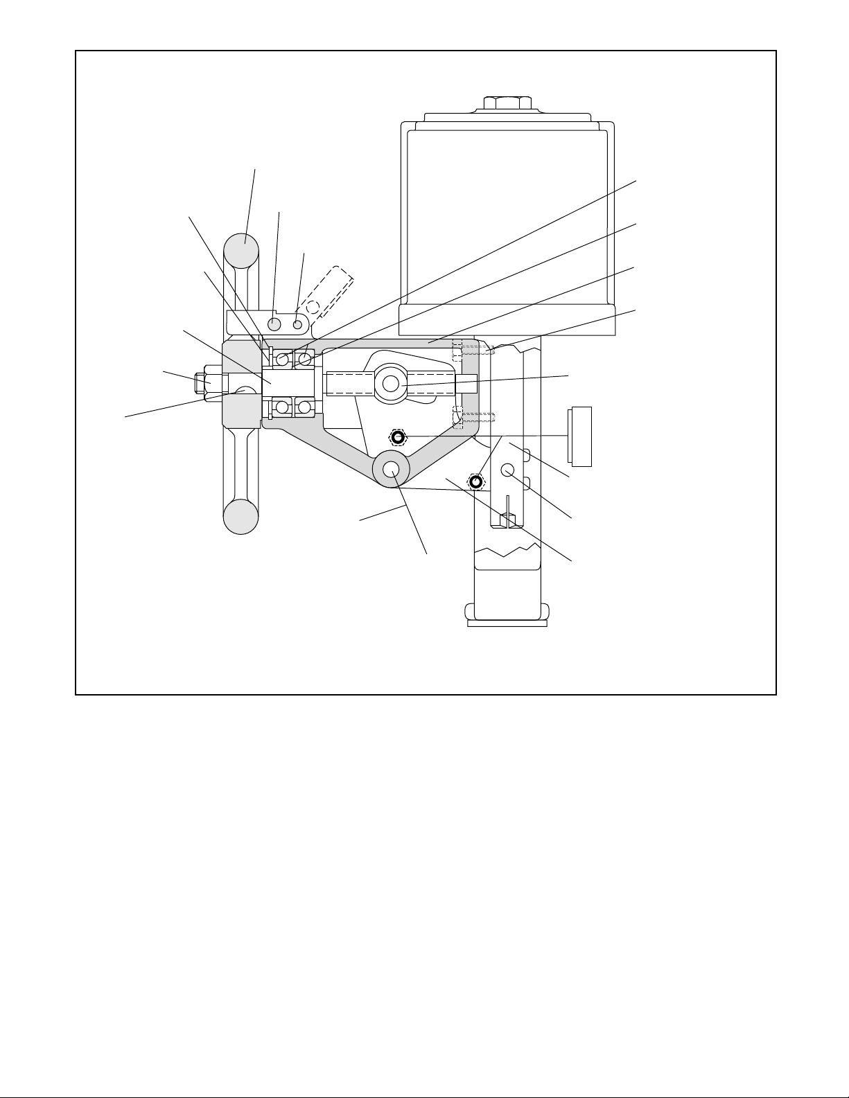
Internal Retaining
Ring
(Item No. 393-9)
Support Spacer
(Item No. 393-6)
Handwheel
(Item No. 393-18)
Locking Bar
(Item No. 393-17)
Pin
(Item No. 393-1)
Bearings
(Item No. 393-8)
Support Washer
(Item No. 393-10)
Housing
(Item No. 393-14)
Handwheel
Screw Shaft
(Item No. 393-13)
Lock Nut
(Item No. 393-4)
Key
(Item No. 393-5)
Handwheel Nut
(Item No. 393-16)
Housing Bolt
(Item No. 333)
Spacer (Item No. 393-7)
Nut (Item No. 393-3)
Bolt (Item No. 393-2)
Not Shown:
Actuator Stem
(Item No. 211)
Grease Fittings
(Item No. 393-15)
Pivot Pin
(Item No. 393-19)
Actuator Pin
(Item No. 372)
Indicator Plate
(Item No. 393-12)
External Retaining Ring
(Item No. 393-20)
Crank Lever
(Item No. 393-11)
Indicator Plate Screws
(Item No. 401)
Figure 1: Size 25 and 50, Side-mounted, Continuously connected Handwheel
NOTE: Item numbers shown above correspond directly to valve’s bill of material. Refer to the bill of material for specific part numbers.
CAUTION: Avoid reattaching the handwheel assembly to the yoke while the actuator remains in
service. If the actuator remains in service during
handwheel reassembIy, ensure that the
handwheel is in the neutral position and that
hands and clothes are kept away from moving
parts to avoid injury.
SIDE-MOUNTED, CONTINUOUSLY
CONNECTED HANDWHEELS, SIZE 100
AND 200 (Linear Actuators only)
Operation
See 'Operation' under Size 25 and 50 Side-mounted
Handwheels section.
necessary; however, periodically examine the handwheel assembly:
1. Check bearing wear by pulling on the handwheel. If
movement more than 1/8-inch in any one direction is
present disassemble and inspect bearings.
2. Keep the handwheel mechanism free from dirt. If
dirt begins to impair handwheel operation, disassemble and clean thoroughly.
Disassembly
To disassemble the side-mounted handwheel on size
100 and 200 linear actuators, refer to Figure 2:
1. Depressurize the process line and actuator to atmospheric pressure. Remove the actuator from
valve (see valve’s maintenance bulletin for instruc-
Maintenance
Because the screw threads are permanently lubricated
with a solid film lubricant, periodical lubrication is not
Flowserve Corporation, Valtek Control Products, Tel. USA 801 489 8611 5-3
tions). Disassemble cylinder by following steps 1-6
under 'Disassembling Actuator' instructions found
in IOM 2 (Cylinder Actuators).
Page 4

WARNING: Failure to repressurize process line
and actuator to atmospheric pressure could
result in serious personaI injury.
2. Slide the stem clamp and bellows off the actuator
stem.
2. Insert upper actuator stem O-ring and replace
O-ring retaining washer and retaining ring.
3. If the pinion shaft bearings have been removed,
press in two new bearings with a dowel of the same
diameter, using a suitable press.
3. Remove the bolt holding the handwheel to the
pinion shaft. Slide handwheel off pinion shaft.
4. Remove the housing set screw at the base of the
handwheel housing and the retaining ring Iock
screw which releases the compression on the
handwheel housing retaining ring.
5. Using two screwdrivers, remove the handwheel
housing retaining ring.
6. Pull the handwheel assembly off the yoke, taking
care not to gall the actuator stem O-ring as it is
pulled from yoke.
7. With the cylinder and piston removed (Step 1), pull
actuator stem straight out of the housing.
8. Remove the bearing spacer, lower bearing and
handwheel nut from the actuator stem.
9. To remove the pinion gear and shaft, remove the
pin retaining ring, rotate the pinion shaft so the pin
will not hit the indicator gear bearing, and push the
pin out. Slide the pinion shaft out of the pinion gear
and housing.
10. Remove the bevel gear, wave spring and the upper
thrust bearing.
11. If the pinion shaft bearings are worn or damaged,
push them out with a suitable press and a dowel the
same size as the bearing’s outside diameter.
12. Remove the upper actuator stem O-ring. (It is not
necessary to remove the O-ring retaining ring and
O-ring retaining washer).
13. The indicator cover plate is attached to the housing
with an adhesive gasket. Gently pry it off.
14. With a screwdriver, remove the two carriage screws
holding the position indicator assembly to the housing. Remove assembly from housing.
15. Normally the position indicator assembly does not
require disassembly. If disassembly is required,
remove the inside stem retaining ring located on the
lower end on the indicator stem. Screw the stem out
of the indicator nut.
Reassembly
To reassemble the side-mounted handwheel on Size
100 and 200 Iinear actuators:
1. Replace and lubricate all O-rings with a silicone
lubricant (Dow Corning® 55M or equivalent). Clean
all internal parts thoroughly before beginning
assembly.
4. To install the bevel gear and bearings, place the
handwheel housing upside down. Lubricate the
upper ball thrust bearing and place it in the housing,
squarely on the machined shoulder.
5. Lubricate the bevel gear thoroughly on the teeth
and the outer surface where it makes contact with
the housing. Lubricate the inside of the square drive
tube. Position the bevel gear assembly into the
housing.
6. Lubricate the pinion gear, shaft and thrust bearings.
Reposition the pinion gear and thrust bearings.
Slide the pinion shaft through the outside of the
housing until it mates with the pinion gear. Rotate
the shaft until the hole in the pinion gear aligns with
the shaft. Insert pin and replace pin retaining ring.
7. Screw the handwheel nut midway onto the actuator
stem and insert the stem through the center of the
bevel gear. Be careful not to score the polished
surfaces of the actuator stem.
8. Position the wave spring on the shoulder of the
bevel gear. Lubricate the lower ball thrust bearing
and place it on the wave spring. Make sure the
bearing fits into the step in the bevel gear with the
wave spring sandwiched in between. Replace the
bearing spacer with the bearing fitting inside the
spacer’s lip.
9. After replacing the lower actuator stem O-ring in the
yoke, insert the yoke into the housing, taking care
not to gall the actuator stem on the stem bushings
or damage the O-ring.
10. Using two screwdrivers, replace the housing retaining ring.
11. Rotate the housing to the desired orientation and
screw-in the retaining ring Iockscrew and reinstall
the housing setscrew until the retaining ring and
housing are locked securely in place.
12. Reinstall the handwheel and handwheel bolt onto
the pinion shaft. Fasten securely with nut.
13. Reassemble the position indicator assembly by
inserting the indicator stem onto the carriage. Screw
the indicator nut into the stem. Replace the stem
retaining ring. Turn the stem until the indicator nut
is centered between the two neutral marks stamped
on the carriage.
14. Turn the handwheel counter-clockwise until the
actuator stem begins to retract. Turn the handwheel
clockwise for two complete turns, so that the handwheel nut is in the neutral position.
5-4 Flowserve Corporation, Valtek Control Products, Tel. USA 801 489 8611
Page 5

Retaining Ring
O-ring Retaining Washer
Upper Actuator Stem
O-ring
Stem Bushing
Upper Ball Thrust Bearing
Housing O-ring
Cylinder Retaining Ring
Carriage Screw
Indicator Carriage
Indicator Cover Plate
Indicator
Stem
Handwheel Housing
Square Drive Tube
Handwheel Nut
Bevel Gear
Wave Spring
Lower Ball
Thrust Bearing
Housing Setscrew
Handwheel Housing
Retaining Ring
Bearing Spacer
Stem Bushing
Actuator Stem
Bellows
Stem Clamp
Indicator Nut
Stem Retaining Ring
Indicator Gear
Thrust Bearing
Pinion Shaft Bearing
Handwheel
Bolt
Pinion Shaft
Nut
Pin Retaining Ring
Retaining Ring Lockscrew
Pinion Gear
Lower Actuator Stem O-ring
Figure 2: Size 100 and 200, Side-mounted, Continuously connected Handwheel
NOTE: Refer to factory for valve’s bill of material item numbers.
Flowserve Corporation, Valtek Control Products, Tel. USA 801 489 8611 5-5
Page 6

NOTE: For correct neutral indication, it is important
to have the handwheel assembly in the neutral
position and the indicator nut between the neutral
marks before installing the indicator assembly in
the housing.
15. With two carriage screws, reinstall the position
indicator assembly, making sure the indicator gear
properly meshes with the pinion gear. Turn the
handwheel to the full open or closed position and
check for correct orientation; readjust if necessary.
With the new adhesive gasket, reattach indicator
cover plate.
16. Replace the housing O-ring.
17. Reattach the bellows and stem clamp to the yoke
and actuator stem.
18. Reassemble the cylinder according to instructions
found in IOM 2.
TOP-MOUNTED, CONTINUOUSLY
CONNECTED HANDWHEELS
Size 100 and 200 (Linear Actuators)
Operation
If air failure occurs, or if manual control of the valve is
desired, the top-mounted, continuously connected handwheel can be operated as follows:
1. Set the three-way bypass valve (located on the
supply line to the positioner) to 'manual' to vent the
air pressure from the actuator.
NOTE: three-way valves are installed in the supply
line only when there is no lock-up system or volume
tank. On volume tank or lock-in-place systems, the
bypass valve is Iocated between the top and bottom
cylinder ports.
2. To open the valve, turn the handwheel counterclockwise to retract the plug.
3. To close the valve, turn the handwheel clockwise to
extend the plug.
4. To return the valve to automatic control, return the
handwheel nut to 'neutral' as shown by the handwheel position indicator and set the three-way
bypass valve to 'auto.' The neutral position is indicated when the top of the screw aligns with the red
line on the cap liner.
5. Adjusting the handwheel nut to a position other than
neutral provides a limit stop function, either limiting
opening or closing.
Maintenance
Since the top-mounted, continuously connected handwheel is totally enclosed, there is generally no need for
periodic maintenance; however, disassembly may be
necessary if the mechanism fails. When reassembling
the handwheel, be sure to thoroughly clean and lubricate the handwheel screw and drive nut with a multipurpose lubricant.
Cap
(Item No. 381)
Gear Operator
(Item No. 393)
Stem Key
(Item No. 373)
Bolt Gasket
(Item No. 379)
Pedestal
(Item No. 389)
Spacer
(Item No. 383)
Bushing
(Item No. 390)
Handwheel Stem
(Item No. 380)
Spring
(Item No. 229)
Piston
(Item No. 225)
Actuator Spacer
(Item No. 228)
Stem Lock Nut
(Item No. 350)
Cap Liner
(Item No. 374)
Cap Extension
(Item No. 387)
Handwheel Screw
(Item No. 388)
Gear Operator Bolts
(Item No. 334)
Pedestal Bolts
(Item No. 333)
Pedestal Gasket
(Item No. 378)
Spring Button
(Item No. 227)
Handwheel O-ring
(Item No. 276)
Stem Pin
(Item No. 372)
Piston Stem O-ring
(Item No. 272)
Actuator Stem
(Item No. 211)
Figure 3: Top-mounted, Continuously
connected Handwheel
NOTE: Item numbers shown above correspond directly to the valve’s
bill of material. Refer to the bill of material for specific part numbers.
Disassembly
Refer to Figure 3:
WARNING: Repressurize line and actuator to atmospheric pressure before disassembling the handwheel or removing the actuator from the valve. Also,
make sure the handwheel screw is in the neutral
position before disassembly. Failure to do so can
cause serious personal injury to occur.
NOTE: These instructions are for air-to-open only.
Instructions for the air-to-close design is the same with
one exception: Pedestal bolts are not used to compress
the spring for air-to-close action; therefore, no spring
tension is released.
1. The handwheel may be disassembled while mounted
on the valve, or the actuator can be removed and
disassembled separately. If a change in the failure
action is required, the entire actuator subassembly
must be removed before proceeding (See 'Disassembling Actuator' in Maintenance Bulletin 1). The
recommended procedure is to remove the actuator
subassembly from the valve.
5-6 Flowserve Corporation, Valtek Control Products, Tel. USA 801 489 8611
Page 7

2. Remove the handwheel cap and the handwheel cap
extension.
3. Loosen stem clamp and slide it off actuator stem.
4. Use a wrench on the actuator stem flats to secure
the position of the stem so it cannot rotate. Remove
the stem locknut.
CAUTION: Damage to the seating surfaces of
the plug and seat can result if the plug is allowed
to rotate during removal of the stem locknut.
5. Unbolt gear operator from pedestal.
NOTE: Bolts are located on the pedestal underneath the gear operator. They are not the bolts
located at the top portion of the gear operator itself.
6. Lift off the gear operator, drive nut assembly and
handwheel screw.
7. Unbolt pedestal from the cylinder actuator. This will
relieve spring tension in the actuator (air-to-open
only).
WARNING: Cylinder is spring loaded. Do not
attempt to remove the handwheel pedestal bolts
without following Step 8 exactly. Failure to do
so can cause serious injury.
8. Remove the six pedestal bolts gradually to relieve
spring tension. This can be done by loosening the
first bolt approximately one-quarter turn, then loosening the bolt directly opposite one-quarter turn
until all bolts have been loosened and the spring
tension is relieved.
NOTE: The bolts are long enough to relieve all
spring tension prior to removing the pedestal.
9. Remove the pedestal.
10. Lift out the spring button and spacer if provided (airto-open only).
11. Remove cylinder retaining ring.
12. Disassemble cylinder from yoke.
13. Remove spring and spring button.
14. Lift out piston, actuator stem and handwheel stem
assembly.
CAUTION: Unless the piston stem O-ring (sealing the two cylinder air chambers) is leaking, do
not remove the handwheel stem from the actuator stem. It may be difficult to realign the stem
pin hole while reassembling the handwheel stem.
15. Remove piston, yoke, and pedestal O-rings.
Reassembly
Refer to Figure 3:
1. Make sure all internal parts are thoroughly cleaned
and lubricated before beginning assembly. Use
new O-rings and gaskets. (O-rings should be lubricated with a silicone lubricant such as Dow Corning
55M or equivalent).
2. Reassemble the cylinder actuator using the appropriate actuator maintenance bulletin.
3. Place the gasket on the cylinder. Place the pedestal
on top of the cylinder. Pedestal should align with
spring button or spring button spacer if used.
NOTE: Check bolting alignment for proper handwheel orientation.
4. Replace aluminum flat washers.
NOTE: To prevent air leaks, lightly coat the washers with a standard pipe sealant.
5. Reassemble pedestal bolts. Begin tightening the
bolting in a manner that will keep the pedestal
square with the cylinder.
WARNING: Failure to keep the pedestal square
with the cylinder may result in damage to the
pedestal O-ring and bushing.
6. Tighten the first bolt approximately one-quarter turn,
then tighten the bolt directly opposite one-quarter
turn. Continue tightening until sufficient gasket compression is applied to seal cylinder and pedestal
tightly. This is necessary to prevent air leakage.
7. Before applying air to the cylinder, make sure the
cylinder retaining ring is installed properly. Feed air
to bottom of cylinder to raise handwheel stem (airto-open only).
8. Insert round end key into slot in handwheel stem.
Remove air. Handwheel stem will retract (air-toopen only).
9. Place gear operator on flat surface with top of the
operator facing down. Insert key in gear operator
drive nut. Install one set of roller thrust bearings in
gear operator.
10. Align the key to the bevel gear key way and install
drive nut. Install second set of roller thrust bearings.
11. Lubricate handwheel screw, and then screw (screw
is left-hand threaded) into the drive nut until screw
bottoms out.
CAUTION: Before completing the next step, be
sure not to allow assembled portion of the
handwheel to drop out of the gear operator.
Failure to do so will cause the drive nut key to
drop out of place. Steps 9 and 10 will then have
to be repeated.
12. Install pedestal gasket.
13. Take the gear operator and handwheel screw assembly and insert it on handwheel stem while
aligning stem key with slot in handwheel screw.
Make sure gear operator is flush with pedestal top.
14. Once the gear operator is flush with the pedestal,
replace bolts and tighten. Tighten the first bolt onequarter turn, then tighten the bolt directly opposite
one-quarter turn. Continue tightening all bolting
until gear operator and pedestal are firmly seated.
15. Install lock nut on handwheel stem, and screw on
handwheel cap extension.
16. Insert gaskets and cap liner (sight glass) into handwheel cap.
Flowserve Corporation, Valtek Control Products, Tel. USA 801 489 8611 5-7
Page 8

17. Screw on handwheel cap until no movement can be
felt in the cap liner.
18. Tighten handwheel cap assembly.
CAUTION: Excessive tightening is not required.
This is not a pressure retaining seal.
Reversing Spring Action
After following the disassembly of the actuator as
outlined, the spring action can be reversed as follows:
1. Remove cylinder retaining ring, cylinder and spring.
2. Drive out the stem pin locking the handwheel stem
to the actuator stem.
3. Screw the handwheel stem off the actuator stem.
Make sure a wrench is used to prevent the actuator
stem from rotating.
CAUTION: Damage to the seating surfaces of
the plug and seat can result if the plug is allowed
to rotate during removal of the handwheel stem.
4. Reinstall the actuator spacer on the opposite side of
the piston. Replace the piston stem O-ring during
this step.
5. Screw the handwheel stem back into the actuator
stem. Realign stem pin hole and reinsert stem pin.
6. Reassemble actuator with spring under the piston
for air-to-open (spring-to-retract). The spring should
be installed over the piston for air-to-close (springto-extend). Make sure the actuator spacer is on the
same side of the piston as the spring.
7. Reassemble by following the instructions in the
'Reassembly' section.
NOTE: The spring button and spring button guide
are not used in the air-to-open configuration and
should be removed and set aside. When changing
to the air-to-close configuration, a spring button and
spring button guide must be obtained from Flowserve
or from existing supply.
TOP-MOUNTED, PUSH-ONLY
HANDWHEELS (Rotary Actuators Only)
Operation
The push-only handwheel can be used to close the
valve or as a limit stop to limit valve opening:
1. If provided, set the three-way bypass valve on
'manual' to vent air pressure to the actuator.
2. Turn handwheel in a clockwise direction to extend
the actuator stem and to lower the valve plug.
3. To return the valve to automatic control, turn the
handwheel counter-clockwise until the handwheel
runs out of threads and stops (neutral position), and
set the three-way valve on 'auto.'
4. To limit the opening of the valve, move the handwheel from neutral to the desired limiting position.
Maintenance
For proper operation of the handwheel, it is important to
Handwheel Stem Nut
(Item No. 348)
Bolt Gasket
(Item No. 379)
Flange
(Item No. 389)
Handwheel
Stem O-ring
(Item No. 276)
Bushing
(Item No. 390)
Handwheel
Stem
(Item No. 380)
Handwheel
(Item No. 393)
Handwheel Key
(Item No. 370)
Flange Gasket
(Item No. 378)
Flange Bolt
(Item No. 333)
Figure 4: Top-mounted,
Push-only Handwheel
NOTE: Item numbers shown above correspond directly to the
valve’s bill of material. Refer to the bill of material for specific part
numbers.
maintain a coat of multi-purpose lubricant on the screw
at all times. To do this:
1. Turn the handwheel counter-clockwise until the
handwheel runs out of threads and stops, exposing
the full length of the screw.
2. Clean and lubricate the exposed threads.
Disassembly
Refer to Figure 4:
1. The handwheel assembly can be disassembled
while mounted on the valve, or the actuator can be
removed and disassembled separately (see the
valve’s maintenance bulletins for instructions).
WARNING: Repressurize line and actuator to
atmospheric pressure before removing the actuator from the valve, or serious personal injury
could result.
2. Rotate the handwheel counter-clockwise until the
handwheel runs out of threads and stops (neutral
position). This releases some of the spring compression.
WARNING: Cylinder is spring loaded. Do not
attempt to remove flange bolts without following Steps 3 and 4 exactly or serious injury can
occur.
3. Remove four of the six handwheel flange bolts,
leaving two opposing bolts.
4. Remove two remaining handwheel flange bolts
5-8 Flowserve Corporation, Valtek Control Products, Tel. USA 801 489 8611
Page 9

slowly and simultaneously, relieving the remaining
spring compression. The bolts are long enough to
relieve all spring compression prior to removing the
flange (as long as the handwheel is in the full
counter-clockwise position).
WARNING: Make sure handwheel is in full
counter-clockwise position. Otherwise, serious
injury may result when removing the flange
bolts.
5. Lift the handwheel/flange assembly from the actuator. Remove the flange gasket.
6. The actuator may now be disassembled according
to the valve’s or actuator’s maintenance bulletin.
7. If it is necessary to replace the handwheel stem Oring, remove handwheel nut and handwheel.
8. Screw the handwheel stem off flange and replace
O-ring. There is no need to replace the bushing.
Reassembly
Refer to Figure 4:
1. Make sure all internal parts are thoroughly cleaned
and lubricated before beginning reassembly. Use
new O-rings and gaskets (O-rings should be lubricated with a silicone lubricant, such as Dow Corning
55 M).
2. Insert new handwheel stem O-ring. Reassemble
handwheel assembly (if disassembled) by screwing the handwheel stem into the flange. Replace the
handwheel, handwheel key and lock nut.
Worm
(Item No. 397-10)
Stem Pin
(Item No. 397-14)
Thrust Roller
(Item No. 397-12)
Thrust Race
(Item No. 397-13)
Stem Bushing
(Item No. 397-7)
Handwheel Key
(Item No. 397-17)
Handwheel
(Item No. 397-1)
Handwheel Locknut
(Item No. 397-18)
Clutch Indicator
(Item No. 397-20-7)
Cover Plate
(Item No. 397-5)
Clutch Shaft
(Item No. 397-20-1)
Small External
Retaining Ring
(Item No. 397-20-4)
Coupling
(Item No. 397-4)
Transfer Case
(Item No. 204)
Clutch Handle
(Item No. 397-1)
Shaft
(Item No. 50)
Handwheel Gear
(Item No. 397-3)
Handwheel Stem
(Item No. 397-2)
External
Retaining Ring
(Item No. 397-16)vva
Large External
Retaining Ring
(Item No. 397-20-3)
Screw
(Item No. 397-20-5)
Cover Plate Bolt
(Item No. 397-8)
Compression
Spring
(Item No. 397-20-2)
Clutch Key
(Item No. 397-6)
Housing
(Item No. 397-9)
Flanged
Bushing
(Item No. 397-15)
3.Reassemble the actuator using the valve’s or
actuator’s maintenance bulletin.
4. Install a new flange gasket.
5. Position the handwheel/flange assembly on the
actuator.
6. Using new bolt gaskets, install two opposing flange
bolts and tighten evenly to compress spring.
7. Remount and tighten four remaining flange bolts.
DECLUTCHABLE HANDWHEELS
(Rotary Actuators Only)
Operation
The declutchable handwheel used on rotary actuators
can be operated as follows:
1. Set the three-way bypass valve to 'manual' to vent
the air pressure from the actuator.
2. Engage the handwheel mechanism by rotating the
clutch handle 90° and allowing it to be fully seated
in the clutch indicator’s deep slot.
3. Rotate the handwheel until the spring loaded clutch
key engages the handwheel gear. At this point the
handwheel mechanism is fully engaged.
Figure 5: Declutchable Handwheel
NOTE: Item numbers shown above correspond directly to the valve’s
bill of material. Refer to the bill of
material for specific part numbers.
4. To open, turn the handwheel counter-clockwise.
5. To close, turn the handwheel clockwise.
6. To declutch the handwheel, rotate the handwheel
until there is little or no load on it. Pull the clutch
handle out and index it 90° until it seats in the clutch
indicator’s shallow slot.
NOTE: It will be difficult to pull out the clutch
handle if the handwheel mechanism is transmitting torque.
Maintenance
Because the handwheel gearbox is packed with grease,
periodic maintenance is not required; however, periodically examine the handwheel:
1. Check for bearing and gear wear by pulling on the
handwheel. If it gives more than 1/8-inch in any one
direction, disassemble and inspect the bearings
and gears.
Flowserve Corporation, Valtek Control Products, Tel. USA 801 489 8611 5-9
Page 10

2. Keep the handwheel mechanism free from dirt. If
dirt begins to impair handwheel operation, disassemble and clean thoroughly.
Disassembly
To disassemble the declutchable handwheel on rotary
actuators, refer to Figure 5:
1. It is not necessary to remove the valve from line to
disassemble handwheel, although it is important to
repressurize the line to atmospheric pressure.
WARNING: Failure to repressurize the line and
actuator to atmospheric pressure could result
in serious personal injury.
2. Remove the four cover-plate bolts and slide the
handwheel assembly off the transfer case and
shaft.
3. Remove the two sockethead screws holding the
clutch indicator to the coupling and remove the
cover plate from the assembly.
4. If disassembly of clutch assembly is necessary,
remove large external retaining ring (use snap-ring
pliers) located on the clutch shaft by the clutch
handle. Slide the clutch handle and clutch indicator
off the shaft. Remove clutch shaft from the cover
plate and slide compression spring off of the shaft.
Remove the small external retaining ring and the
clutch key from the shaft.
5. If it is necessary to remove the handwheel from the
handwheel stem, remove the handwheel lock nut
and slide the handwheel and handwheel key off the
handwheel stem.
NOTE: All stems use either an external retaining
ring or a shoulder on the stem to hold the handwheel
in place. The retaining ring does not require removal
except for replacement.
6. Drive the stem pin through the stem and worm gear
until it nearly touches the housing wall. Rotate the
stem 180° and pull out the pin with a pair of vice
grips or similar tool.
7. Slide the stem out of the assembly. Simultaneously
slide the handwheel gear off the coupling and
remove the worm. Remove the two sets of thrust
rollers and races. The two stem bearings should be
visually inspected for damage or wear. If removal of
the stem bushings is necessary, push them out
using a dowel of the same diameter and a suitable
press.
8. Pull the coupling out of the housing. Inspect the
flanged bushing for wear. If necessary, remove with
an appropriate press and dowel.
Reassembly
To reassemble the declutchable handwheel on rotary
actuators, refer to Figure 5:
1. Clean all parts thoroughly before reassembling the
declutchable handwheel.
2.To reassemble the clutch assembly (if disassembled), slide the clutch key onto the small end of
the clutch shaft and secure with the small external
retaining ring. Install the compression spring over
the shaft. Position the clutch indicator on the outside of the cover plate. Slide the large end of the
clutch shaft through the clutch indicator from the
inside of the cover. Install the clutch handle and
large external retaining ring.
3. Using a press, install new stem bushings (if removed).
4. Using a press, install a new flanged bushing (if
removed). Lubricate and reinstall the coupling. Note
that the coupling rotates inside the flanged bushing.
5. Thoroughly lubricate the worm and handwheel gear.
Holding the worm engaged in the gear (as shown in
Figure 5), slide the handwheel gear onto the
coupling.
6. Install a thrust bearing at each end of worm, making
sure roller is sandwiched between the two races.
7. Slide the handwheel stem through the stem bearings and worm gear. Align pin holes in the worm
gear and stem, and drive pin into place.
8. If the handwheel was removed from the stem, insert
the handwheel key into its slot in the handwheel
stem. Slide the handwheel on and secure it with the
handwheel locknut.
9. Pack the entire inside volume of the handwheel
housing with a multi-purpose grease.
10. Rotate the coupling until its slot aligns with the slot
in the handwheel gear. Replace the cover plate,
making sure the clutch key slides into the slots.
Rotate the clutch handle until it fits into the bottom
of the deep slot in the indicator and allows the clutch
key to engage the gear and coupling. If the key does
not engage, rotate the handwheel back and forth
until it does. Rotate the clutch indicator until the two
screw holes line up and the pointer points to the
stroke indicator scale. Fasten in place with the two
screws.
CAUTION: Since the gear has limited rotation,
the splines on the shaft and coupling must be
correctly oriented. Incorrect alignment will result in limited handwheel rotation.
11. To correctly orient the splined shaft and coupling,
check to see if the valve is open or closed. If closed,
rotate the handwheel clockwise with the clutch
engaged until the gear hits the stop. Next, slide the
handwheel assembly onto the splined shaft, making sure the line on the end of the shaft lines up
exactly with the closest line on the coupling. Reinstall the four cover plate bolts.
12. If the handwheel does not stroke the valve fully, the
splined shaft and coupling are not aligned correctly.
Repeat Step 11.
5-10 Flowserve Corporation, Valtek Control Products, Tel. USA 801 489 8611
Page 11

Jam Nut
(Item No. 350)
Limit Stop Bolt
(Item No. 380)
Limit Stop Hub
(Item No. 391)
Hub Gasket
(Item No. 248)
O-ring
(Item No. 376)
Spring Button
(Item No. 227)
Cylinder
(Item No. 202)
6. Tighten the limit stop jam nut firmly against the
locking stop hub.
Disassembly
Refer to Figure 6:
WARNING: Repressurize line and actuator to atmospheric pressure before disassembling the handwheel or removing the actuator from the valve, or
serious personal injury could result.
1. The limit stop may be disassembled while mounted
on the valve, or the actuator can be removed and
disassembled separately (see the valve’s maintenance bulletins for instructions).
2. Vent air pressure on both sides of the piston.
Loosen the limit stop jam nut and screw the limit
stop bolt counter-clockwise until it can be removed
from the limit stop hub. Remove the O-ring and jam
nut from the limit stop bolt.
3. Screw the limit stop hub off the cylinder. Larger
sizes are designed with an internal flanged hub. If
this is the case, remove the flange bolts. Remove
the gasket from the limit stop hub.
4. Actuator may now be disassembled according to
Maintenance Bulletin 2.
Figure 6: Push-only Limit stop
NOTE: Item numbers shown above correspond directly to the valve’s
bill of material. Refer to the bill of material
for specific part numbers.
PUSH-ONLY LIMIT STOPS
(Linear Actuators Only)
Operation
The push-only limit stop is used to limit valve opening.
To set the limit stop:
1. Loosen the limit stop jam nut (see Figure 6).
2. To lengthen the stroke, screw the limit stop bolt
counter-clockwise from the locking stop hub until
the desired position is reached. To shorten the
stroke, screw the limit stop bolt clockwise into the
locking stop hub until the desired position is reached.
3. Tighten the limit stop jam nut firmly against the
locking stop hub.
Maintenance
For proper maintenance of the limit stop, it is important
to maintain a coat of multi-purpose Iubricant on the limit
stop bolt threads at all times. To do this:
1. Vent air pressure on both sides of piston.
2. Loosen the limit stop jam nut.
3. Extend the limit stop bolt until the entire length of the
threaded portion is exposed.
4. Clean and lubricate the threads.
5. Return the limit stop bolt to desired position.
Reassembly
Refer to Figure 6 and proceed as follows:
1. Make sure all internal parts are thoroughly cleaned
and lubricated before beginning reassembly. Use
only new O-rings and gaskets (O-rings should be
lubricated with a silicone lubricant, such as Dow
Corning 55 M). Reassemble the actuator according
to Maintenance Bulletin 2.
2. Install a new O-ring on the limit stop bolt and a new
gasket on the limit stop hub.
3. Screw the limit stop hub into the cylinder or on larger
sizes, reinstall hub and flange bolts.
4. Make sure the end of the hub seats properly with the
spring button. Tighten the limit stop hub (or flange
bolts) only enough to make an adequate air seal
with the gasket.
5. After installing the jam nut on the limit stop bolt,
screw the limit stop bolt into the limit stop hub until
the desired position is reached.
6. Tighten the jam nut against the limit stop hub.
PULL-ONLY LIMIT STOPS
(Linear Actuators Only)
Operation
WARNING: The limit stop bolt and jam nuts are
moving parts. Keep hands, hair or clothing clear
during operation or serious injury can result.
The pull-only limit stop is used to limit valve closing. To
set the limit stop:
1. Loosen the limit stop jam nuts (see Figure 7).
2. Apply air under the piston until the limit position is
reached.
Flowserve Corporation, Valtek Control Products, Tel. USA 801 489 8611 5-11
Page 12

3. Readjust the jam nuts until they are seated next to
the limit stop flange. Tighten jam nuts securely
against each other.
Maintenance
For proper maintenance, maintain a coat of multipurpose lubricant on the limit stop bolt threads at all
times. To do this:
1. Apply air under the piston until the actuator is fully
retracted, exposing the bolt threads.
2. Remove the limit stop jam nuts.
3. Clean and lubricate the threads.
4. Return limit stop jam nuts to the desired position.
5. Securely tighten the jam nuts against each other.
Jam Nut
(Item No. 350)
Bolt Gasket
(Item No. 379)
Flange
Gasket
(Item No. 378)
WARNING:
MOVING PARTS!
KEEP HANDS CLEAR
Flange Bolts
(Item No. 333)
Limit Stop
Flange
(Item No. 389)
Limit Stop Bolt
(Item No. 380)
Limit Stop
Flange O-ring
(Item No. 276)
Disassembly
Refer to figure 7:
WARNING: Repressurize the line and actuator to
atmospheric pressure before disassembling the
limit stop or removing the actuator from the valve,
or serious personal injury could result.
1. The limit stop may be disassembled while mounted
on the valve, or the actuator can be removed and
disassembled separately (see the valve’s maintenance bulletin for instructions).
2. Vent air on both sides of the piston.
3. Loosen and remove the limit stop jam nuts.
WARNING: Cylinder is spring loaded. Do not
attempt to remove the flange bolts without following Steps 4 and 5 exactly or serious injury
could occur.
4. Remove all but two opposing flange bolts and bolt
gaskets.
5. Remove the two remaining bolts slowly and simultaneously, relieving the remaining spring compression. The bolts are of sufficient length to relieve all
spring compression prior to releasing the flange.
6. Lift the limit stop flange off the cylinder, taking care
not to damage the limit stop bolt threads and
bushing. Remove flange gasket from top of cylinder.
7. Remove the limit stop flange O-ring.
8. The actuator may now be disassembled according
to Maintenance Bulletin 2.
9. Unless the limit stop bolt is to be replaced, do not
remove the pin from the actuator stem, since realigning the pin hole in both pieces is difficult.
However, if it is necessary to replace the piston
stem O-ring, drive the stem pin out and screw the
limit stop bolt off the actuator stem.
Reassembly
Refer to Figure 7:
1. Make sure all internal parts are thoroughly cleaned
and lubricated before beginning reassembly. Use
Bushing
(Item No. 390)
O
C
Cylinder
(Item No. 202)
Pin
(Item No. 372)
Piston Stem
O-ring
(Item NO. 272)
Figure 7: Pull-only Limit Stop
NOTE: Item numbers shown above correspond directly to the valve’s
bill of material. Refer to the bill of material
only new O-rings and gaskets (O-rings should be
lubricated with a silicone lubricant such as Dow
Corning 55 M).
2. Reassemble the actuator according to Maintenance
Bulletin 2. If the limit stop bolt is being replaced,
replace the piston stem O-ring and screw the limit
stop bolt and the actuator stem together. Realign
the pin hole and drive the stem pin firmly in place.
Reassemble the cylinder and retaining ring according to Maintenance Bulletin 2.
3. Replace the limit stop flange O-ring. Install the
flange and a new flange gasket on the cylinder.
4. Using new bolt gaskets, install two opposing boltsand tighten evenly to compress the spring.
5. Reassemble the four remaining bolts and bolt gaskets. Tighten sufficiently to form a proper seal with
the flange gasket and bolt gasket.
6. Apply air under the piston until the desired limit
position is reached.
7. Reinstall the limit stop jam nuts until they are seated
against the limit stop flange. Tighten both jam nuts
firmly against each other.
or specific part numbers.
5-12 Flowserve Corporation, Valtek Control Products, Tel. USA 801 489 8611
 Loading...