

Page 1
Installation
Experience In Motion
Instructions
GCX Series
Single bellows cartridge seal incorporating graphite secondary seals
to meet the demands of the chemical processing industry
Page 2

Description
The GCX seal is a cartridge mounted mechanical seal, designed for ease
of installation and reliable operation. No seal setting dimensions are
required. Removable centering tabs provide proper alignment. The GCX
seal is designed for harsh chemical environments where conventional
O-ring based seal designs are unsuccessful. Graphite secondary seals
are used to provide nearly universal chemical compatibility towards
aggressive chemicals. The stationary bellows conguration allows the
seal to compensate for inadvertent misalignment of the seal chamber
face, and helps to prevent clogging and hang-up of the bellows on the
atmospheric side of the seal.
Installation according to the following steps will assure long trouble free
life of the seal.
1 Equipment Check
1.1 Follow plant safety regulations prior to equipment disassembly:
• lock out motor and valves.
• wear designated personal safety equipment.
• relieve any pressure in the system.
• consult plant MSDS les for hazardous material regulations.
1.2 Disassemble equipment in accordance with equipment
manufacturer’s instructions to allow access to seal installation area.
1.3 Remove existing mechanical seal and bushing or compression
packing and packing gland.
1.4 Make sure the shaft or sleeve and the seal housing face are
clean and free of burrs, cuts, dents, or corrosion that might cause
leakage past the sleeve gasket or gland gasket. Replace worn
shaft or sleeve. Remove sharp edges from keyways and threads.
2
Page 3
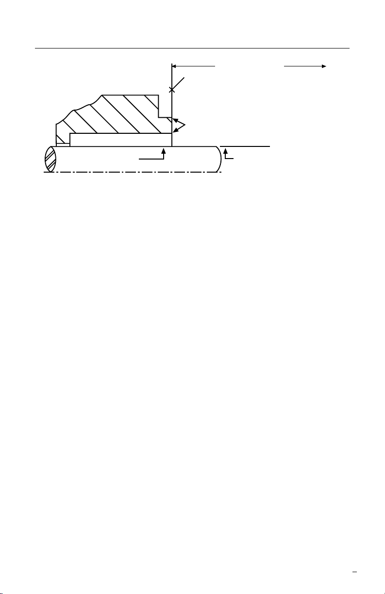
Seal Chamber Requirements Figure 1
To first obstruction
Face of seal housing to be square to the axis
of the shaft to within 0.013 mm per millimeter
(0.0005 inches) of seal chamber bore FIM and
have a √1.6
μm (63 μinch) R finish or better
a
Gland pilot can be at either of these
register locations, concentric to within
0.13 mm (0.005 inch) FIM of shaft or sleeve OD
Seal housing bore to have √3.2 μm
(125 μinch) R finish or better
Sleeve or shaft finish to be
0.8 μm (32 μinch) R or better
a
a
Shaft or sleeve OD
+0.000 mm (+0.000 inch)
-0.050 mm (-0.002 inch) ANSI
+0.000 mm (+0.000 inch) API 610/682
-0.025 mm (- 0.001 inch) DIN/ISO
• Bearings must be in good condition
• Maximum lateral or axial movement of shaft (end play) = 0.25 mm (0.010 inch) FIM
• Maximum shaft runout at face of seal housing = 0.05 mm (0.002 inch) FIM
• Maximum dynamic shaft deflection at seal housing = 0.05 mm (0.002 inch) FIM
1.5 Check equipment dimensions to ensure that they are within the
specications shown in Figures 1, 2, and 3. Critical dimensions
from Figure 2 include:
• Box Bore (dim ØC)
• Box Depth (dim G)
• Distance to First Obstruction (dim K)
• Pump Frame accommodates Gland OD (dim E)
1.6 Check gland bolting to ensure that bolt diameter and bolt circle
conform to the dimensions shown in Figure 2 and 3. (dims C & M)
1.7 Handle the GCX with care, it is manufactured to precise tolerances.
The sealing faces of the GCX seal are the stationary face and the
rotating face. They are lapped at to within three helium light bands
(34.8 millionths of an inch). Keep the seal faces perfectly clean at
all times.
3
Page 4
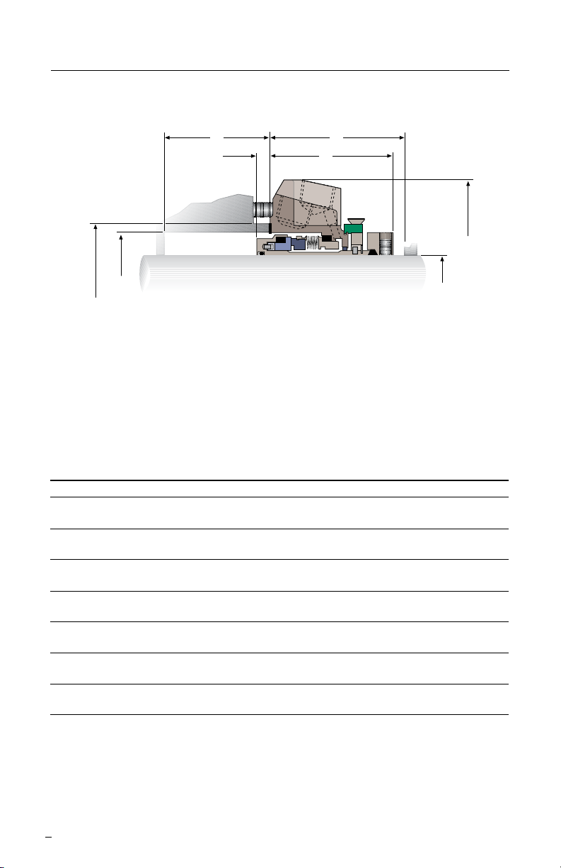
GCX Dimensional Data in millimeters (inches) - Standard Bore Figure 2
G
F
K
J
Ø E
Ø C
Ø D
Ø A
Shaft Size
& Seal Size
A C D E F G J K L M
Shaft & Box Bore Gasket Gland Sleeve Box Depth Outboard Dist. to Obst Bolt Bolt
Seal Size Min Max OD OD Penetration Min Seal Length Min Circle Slot Dia.
(1.125) N/A N/A N/A N/A N/A N/A N/A N/A N/A
33, 35 N/A N/A N/A N/A N/A N/A N/A N/A N/A
(1.375) N/A N/A N/A N/A N/A N/A N/A N/A N/A
44.45 63.5 73.0 80.0 25.5 - 127.0 6.5 8.1 64.3 66.5 98.4 14.3
(1.750) (2.500 2.875) (3.15) (4.94 - 5.00) (0.256) (0.318) (2.530) (2.620) (3.875 (0.562)
45, 48 66.7 73.0 80.0 125.5 - 127.0 6.5 8.1 64.1 65.5 98.4 14.3
(1.875) (2.625 2.875) (3.15) (4.94 - 5.00) (0.256) (0.318) (2.522) (2.580) (3.875) (0.562)
53 73.0 82.6 89.9 150.9 - 152.4 7.0 8.6 64.3 65.8 112.8 19.1
(2.125) (2.875 3.250) (3.54) (5.94 - 6.00) (0.275) (0.337) (2.530) (2.590) (4.440) (0.750)
86.1 95.3 101.2 160.5 - 162.0 7.9 9.4 64.1 66.8 123.8 19.1
(2.375) (3.388 3.750) (3.985) (6.32 - 6.38) (0.310) (0.372) (2.522) (2.630) (4.875) (0.750)
Goulds 91.1 92.1 100.1 160.5 - 162.0 16.5 19.2 64.0 66.3 123.8 19.1
(2.500-) (3.587 3.625) (3.942) (6.32 - 6.38) (0.651) (0.755) (2.521) (2.609) (4.875) (0.750)
IDP 85.7 95.2 100.1 179.3 - 180.8 4.0 5.6 76.6 79.7 155.6 14.2
(2.500-) (3.375 3.750) (3.942) (7.06 - 7.12) (0.158) (0.220) (3.014) (3.139) (6.125) (0.560)
65 92.1 109.5 117.2 182.6 - 184.2 6.7 8.3 90.1 93.3 142.9 22.2
(2.625) (3.625 4.312) (4.615) (7.19 - 7.25) (0.264) (0.326) (3.547) (3.672) (5.625) (0.875)
N/A - The GCX seal is not available in this size configuration
The images of parts shown in these instructions may differ visually from the actual
parts due to manufacturing processes that do not affect the part function or quality.
4
Page 5

GCX Dimensional Data in millimeters (inches) - Enlarged Bore Figure 3
G
F
K
J
Ø E
Ø C
Ø D
Ø A
Shaft Size
& Seal Size
A C D E F G J K L M
Shaft & Box Bore Gasket Gland Sleeve Box Depth Outboard Dist. to Obst Bolt Bolt
Seal Size Min Max OD OD Penetration Min Seal Length Min Circle Slot Dia.
53.1 74.0 79.2 112.8 - 114.3 23.9 25.4 49.5 50.3 95.3 11.2
(1.125) (2.090 2.912) (3.120) (4.44 - 4.50) (0.940) (1.000) (1.950) (1.98) (3.750) (0.440)
33, 35 63.4 80.3 85.5 131.8 - 133.4 19.3 20.8 49.5 50.8 101.6 11.2
(1.375) (2.495 3.162) (3.365) (5.19 - 5.25) (0.760) (0.82) (1.950) (2.000) (4.000) (0.440)
88.9 105.5 110.6 163.6 - 165.1 4.2 5.8 66.5 70.3 98.4 14.3
(1.750) (3.500 4.152) (4.355) (6.44 - 6.50) (0.166) (0.228) (2.620) (2.769) (3.875) (0.562)
45, 48 92.1 99.2 104.4 147.8 - 149.4 0.0) 0.0 72.5 74.9 127.0 14.3
(1.875) (3.625 3.907) (4.110) (5.82 - 5.88) (0.000) (0.000) (2.854) (2.947) (5.000) (0.562)
53 93.3 117.0 121.9 176.3 - 177.8 7.0 8.6 64.3 65.8 142.9 19.1
(2.125) (3.870) (4.607) (4.800) (6.94 - 7.00) (0.275) (0.337) (2.530) (2.590) (5.625) (0.750)
2.375 N/A N/A N/A N/A N/A N/A N/A N/A N/A
Goulds 95.2 124.6 129.9 201.7 - 203.2 12.5 14.0 68.1 71.2 160.4 19.1
(2.500) (3.750 4.907) (5.115) (7.94 - 8.00) (0.492) (0.552) (2.680) (2.805) (6.313) (0.750)
IDP 95.2 124.6 129.9 179.3 - 180.8 12.5 14.0 68.1 71.2 155.6 14.3
(2.500) (3.750 4.907) (5.115) (7.06 - 7.12) (0.492) (0.552) (2.680) (2.805) (6.125) (0.562)
65 117.5 124.8 129.9 176.3 - 177.8 0.0 0.0 98.5 101.7 152.4 22.2
(2.625) (4.625 4.912) (5.115) (6.94 - 7.00) (0.000) (0.000) (3.879) (4.004) (6.000) (0.875)
N/A - The GCX seal is not available in this size configuration
5
Page 6

2 GCX Installation
Note: The GCX seal is shipped with the sleeve and gland graphite
gaskets uninstalled. These parts must be assembled onto the seal prior
to installation of the seal into the pump. The gaskets are very fragile;
handle with care.
Note: No seal setting measurements are needed to install the
seal. Instructions are for radially split case end-suction ANSI pumps.
Modication of the procedure may be required for other style pumps.
Consult your Flowserve Representative.
2.1 Tools needed for installation:
• An open end wrench for the gland bolt nuts
• 5/16” open end wrench for the collar bolts
• 3/32” Allen wrench (provided)
• 1/8” Allen wrench (provided)
2.2 Loosen the collar cap screws and remove the drive collar from
the seal assembly.
2.3 Install the sleeve
gasket into the drive
collar. Do not use any
sharp instruments
for installation of the
gasket. Loosely reattach
the collar and gasket
assembly to the seal
with the collar bolts.
See Figure 4.
Figure 4
2.4 Adhere the gland gasket to the gland centered on the register.
Dabs of silicone grease or a spray adhesive may be used to hold
the gasket in place.
2.5 Lubricate the shaft or sleeve lightly with silicone lubricant unless
otherwise specied.
2.6 Tighten the Centering Tab screws.
6
Page 7

2.7 Install the complete GCX
cartridge assembly onto the
shaft or sleeve with the setting
devices near the bearing
housing. See Figure 5.
2.8 Install the pump back plate
(seal chamber) and bolt it in
place on the bearing frame.
See Figure 6.
Figure 5
Figure 6
7
Page 8

2.9 Position the GCX with the gland tight against the seal chamber
face. If equipment conditions allow, position gland with the outlet
port or plugged ush port as close to the 12:00 o’clock position as
possible. See Sections 3 and 4 for further piping considerations.
Otherwise turn the gland so that the vent tap is as close to the
12:00 o’clock position as possible so that the ush piping will clear
the bearing frame.
Caution: Setting devices should not be removed or loosened before
tightening the gland bolts and tightening the set screws to
the shaft.
Tighten the gland nuts evenly in a diagonal sequence. Do not over
tighten the gland nuts, as this can warp seal parts and cause
leakage. The suggested GCX gland nut torque values are as
follows for seals with these shaft sizes:
20 N-m (15 ft-lbs) 27 N-m (20 ft-lbs)
33 mm (1.125 inch) 53 mm (2.125 inch)
to to
48 mm (2.000 inch) 65 mm (2.625 inch)
2.10 Assemble the pump. Avoid
pipe strain. Align coupling
properly.
2.11 With the impeller, shaft,
coupling, and bearings in
their nal operating positions,
tighten the collar bolts
evenly to compress the
sleeve gasket. Tighten until
the gap between the drive
collar and the adjusting collar
is 3/32” for sizes 33 - 65 mm
(1.000 to 2.500 inch), and
1/8” for the 2.625 inch
seal size. This gap can be
checked with the supplied
Allen wrenches by inserting
the wrenches between the
collars and matching the
width across the ats to the
gap. The gap should be even,
and all of the collar bolts
should be tight. See Figure 7.
8
Figure 7
Page 9

2.12 Tighten the set screws. See Figure 8.
Suggested minimum torque values for
set screws are as follows:
Shaft Size Set Screw Size in-lbs
33 - 53 mm 1/4” 5.6 N-m
(1.125 - 2.500 inch) (50 in-lbs)
65 mm 5/16” 10.4 N-m
(2.625 inch) (92 in-lbs)
Figure 8
Note: If the equipment shaft has a hardness of greater than 84 Rockwell
B (162 Brinell), consult your Flowserve Representative for alternate set
screw material recommendations.
2.13 Remove the setting devices
from the sleeve collar.
See Figure 9. Save the tabs
and fasteners for future use
when the pump impeller is
reset or when the seal is
removed for repairs.
Figure 9
2.14 Turn the shaft by hand to ensure unobstructed operation.
2.15 See Operational Recommendations before start-up.
9
Page 10

3 Single Seal Piping and Operational Recommendations
3.1 Install an adequate seal ush system. The GCX requires a clean
cool environment for maximum seal life. With a clean cool product,
use a bypass ush from the pump discharge (Plan 11) or a bypass
ush to the pump suction (Plan 13). With clean hot products
use a bypass ush through a cooler (Plan 21). With abrasive
products or products that are incompatible with the seal, use a ush
from a clean external source (Plan 32). Consult your Flowserve
Representative for assistance with choosing the appropriate ush
system.
3.3 Taps in the gland are quench and drain ports used for uid
quenching, Plan 62. If they are not used, they should be plugged
with pipe plugs.
3.4 Remove lock outs on pump and valves.
3.5 Do not start up the equipment dry to check motor rotation or for any
other reason. Open valves to ood pump with product uid. Ensure
that the seal ush system is operating. Vent air from the casing of
the pump and the seal chamber before start-up.
3.6 Observe the start-up. If the seal runs hot or squeals, check the seal
ush system. Shut down the equipment immediately if the seal
becomes hot or squeals.
4 Operational Recommendations
4.1 Do not exceed corrosion limits. The GCX is designed to resist
corrosion by most chemicals. However, do not expose the GCX
materials of construction to products outside of their corrosion limits.
The GCX assembly drawing lists the materials of construction.
Consult your Flowserve Representative for chemical resistance
recommendations.
4.2 Do not exceed the recommended maximum pressure and speed
limits of 13.8 bar (200 psi) and of 3600 rpm.
4.3 Do not exceed the temperature limit of 204°C (400°F).
4.4 Do not start up or run the GCX dry. Process uid must be in the
pump volute at all times during seal operation.
For special problems encountered during installation, contact your nearest
Flowserve Sales and Service Representative or Authorized Distributor.
10
Page 11

5 Repair
This product is a precision sealing device. The design and dimension
tolerances are critical to seal performance. Only parts supplied by
Flowserve should be used to repair a seal. To order replacement parts,
refer to the part code and B/M number. A spare backup seal should be
stocked to reduce repair time.
When seals are returned to Flowserve for repair, decontaminate the
seal assembly and include an order marked "Repair or Replace."
A signed certicate of decontamination must be attached.
A Material Safety Data Sheet (MSDS) must be enclosed for any
product that came in contact with the seal. The seal assembly will be
inspected and, if repairable, it will be rebuilt, tested, and returned.
11
Page 12

TO REORDER REFER TO
flowserve.com
USA and Canada
Kalamazoo, Michigan USA
Telephone: 1 269 381 2650
Telefax: 1 269 382 8726
Europe, Middle East, Africa
Roosendaal, the Netherlands
Telephone: 31 165 581400
Telefax: 31 165 554590
Asia Pacific
Singapore
Telephone: 65 6544 6800
Telefax: 65 6214 0541
Latin America
Mexico City
Telephone: 52 55 5567 7170
Telefax: 52 55 5567 4224
B/M #
F.O
.
FIS172eng REV 02/12 Printed in USA
To find your local Flowserve representative
and find out more about Flowserve Corporation,
visit www.flowserve.com
Flowserve Corporation has established industry leadership in the design and manufacture of its products. When
properly selected, this Flowserve product is designed to perform its intended function safely during its useful life.
However, the purchaser or user of Flowserve products should be aware that Flowserve products might be used
in numerous applications under a wide variety of industrial service conditions. Although Flowserve can provide
general guidelines, it cannot provide specific data and warnings for all possible applications. The purchaser/user
must therefore assume the ultimate responsibility for the proper sizing and selection, installation, operation, and
maintenance of Flowserve products. The purchaser/user should read and understand the Installation Instructions
included with the product, and train its employees and contractors in the safe use of Flowserve products in connection
with the specific application.
While the information and specifications contained in this literature are believed to be accurate, they are supplied for
informative purposes only and should not be considered certified or as a guarantee of satisfactory results by reliance
thereon. Nothing contained herein is to be construed as a warranty or guarantee, express or implied, regarding any
matter with respect to this product. Because Flowserve is continually improving and upgrading its product design,
the specifications, dimensions and information contained herein are subject to change without notice. Should any
question arise concerning these provisions, the purchaser/user should contact Flowserve Corporation at any one of
its worldwide operations or offices.
© Flowserve Corporation (2012)
 Loading...