

Page 1
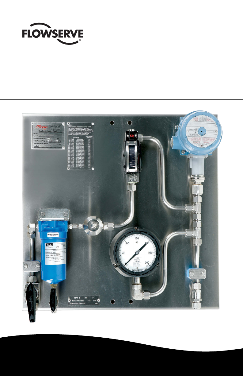
Flowserve Gas Barrier Control System
Experience In Motion
Installation
& Operation
Instructions
Page 2

1 Introduction
1.1 Flowserve Gas Control Systems combine ow monitoring and control elements in a
self-contained, easy-to-use unit for successful operation of pressurized or unpressurized
Flowserve Gas Seals. Control System designs range from simple standard to complex
custom including various elements and panel designs per specic gas seal and application requirements. The purpose of this document is to provide general installation and
operation instructions while the Control System assembly drawing and Gas Seal assembly
drawing should be referenced for additional instructions or requirements.
1.2 Control System elements may include, but are not limited to, the following:
Filter/Regulator - regulates pressure and lters plant gas supply to the seal.
Pressure Indicator - indicates gas pressure supplied to the seal
Flow Indicator - indicates gas ow rate to the seal.
Check Valve - protects control system from product contamination during upset
pressure reversal.
Fixed Orice - restricts maximum ow rate to seal in the event of seal failure.
Maintenance Bypass Valve - three-way valve used to bypass control system with
temporary, secondary gas supply for maintenance of Control System.
Pressure Alarm/Switch - electronic sensor used to alarm at low gas pressure condition.
Flow Alarm/Switch - electronic sensor used to alarm at high gas ow rate conditions.
1.3 Control Systems are used with at least the following Flowserve Gas Seal types: GF-200,
GX-200, Bufferpac 982, MD-200, ML-200, Circpac MD, GSL, GSS and GSD.
2 Before Installation
2.1 See enclosed assembly drawing for Control System component reference and special
instructions. Review instructions on the Flowserve seal assembly drawing for additional
piping recommendations. For technical assistance contact your local Flowserve Representative or Authorized Distributor.
2.2 Review the minimum/maximum system pressures that might be encountered at the
following: A. Inlet Plant Nitrogen or Air supply to control system
B. Process (seal chamber) pressure (for Plan 74 systems)
C. Vapor/liquid collection system pressure (for Plan 72 systems)
2.3 Conrm that all connecting piping, ttings, indicators and accessories are rated properly.
2.4 Conrm the hazardous area classication where the Control System is to be installed.
Conrm that the equipment ordered meets the area classication.
2.5 Inspect all connections for dirt or contamination. Blow out all tubing with instrument air
or nitrogen.
2.6 Conrm that a plug or block valve has been installed in the seal drain connection.
3 Installation
3.1 Securely mount the Control System as close as possible to the Gas Seal such that line
losses are minimal. Especially when supplying segmented ring seals, measure line losses
(pressure drop) before completing nal piping to seal. Tighten all mounting hardware prior to
making any tubing connections.
The images of parts shown in these instructions may differ visually from the actual
parts due to manufacturing processes that do not affect the part function or quality.
2
Page 3

3.2 Use 316 stainless steel tubing to connect the Plant Nitrogen or Air supply to the Supply Inlet
port of the Control System. Minimum recommended tubing sizes are as follows unless
otherwise specied:
3/8 inch for mechanical seals (e.g. GF-200, GX-200, ML-200, GSL, GSD)
1/2 inch for segmented ring seals up to 127 mm (5.000 inch) seal size (e.g. Circpac MD)
3/4 inch for segmented ring seals up to 254 mm (10.000 inch) seal size
Contact Flowserve for all other seal types or the use of smaller tubing sizes
3.3 Use same size 316 stainless steel tubing as Step 3.2 to connect the Supply Outlet of the
Control System to the inlet of the Gas Seal.
3.4 Special Components
Maintenance Bypass Valve
Two ports are available for piping connection. Connect the port labeled “To Seal” to the inlet
of the Gas Seal as indicated in Step 3.3. The port labeled “Bypass” is connected to a
temporary gas source when Control System maintenance is required. This port is otherwise
not used. Set the bypass valve to the “Normal” position during normal operation.
Pressure or Flow Alarms
Connect alarm wiring to plant system per NEC 500 and plant specications.
4 Operation
4.1 Turn on the Nitrogen or Air supply to the Control System.
4.2 For Plan 74 pressurized systems:
Adjust the Pressure Regulator until the Pressure Gage reads a predetermined pressure
above the pressure of the product being sealed (seal chamber pressure), taking into
consideration all phases of equipment operation. Consult the Flowserve Gas Seal assembly
drawing for the recommended barrier pressure over product pressure.
For Plan 72 unpressurized systems:
Adjust the Pressure Regulator until the Pressure Indicator reads a predetermined
pressure typically nominally above atmospheric or vapor/liquid collection system pressure.
Consult the Flowserve Seal Assembly Drawing for the recommended buffer pressure.
4.3 If a ow switch was supplied, and no set point was specied at time of order, it is factory set
at 5 SCFH rising. Please refer to the ow switch literature included in the manual for the
proper procedure to reset the switch set point.
4.4 If a pressure switch was supplied, and no set point was specied at time of order, it is
factory set at 1 bar (15 psig) falling. Please refer to the pressure switch literature included in
the manual for the proper procedure to reset the switch set point.
Note: For Plan 74 systems, the pressure switch set point should be 1.2 bar (17 psig)
above the pressure of the product being sealed (seal chamber pressure). Example: If seal
chamber pressure is 1.7 bar (25 psig), the pressure switch set point should be 2.9 bar
(42 psi) falling.
4.5 Check all connections to and from the control system for leakage with a leak detection
solution or soapy water.
4.6 Maintain the seal gas pressure even when the pump is not running.
4.7 The equipment is now ready for start up.
3
Page 4

TO REORDER REFER TO
flowserve.com
B/M #
F.O
.
5 Maintenance
5.1 As necessary or as part of a scheduled maintenance program, elements of the Control
System may require maintenance. If Control System maintenance is performed while the
Control System is actively supporting a seal, extreme care must be taken to work safely with
pressurized gas while not disrupting the gas supply to the seal.
The following instructions are for Control Systems equipped with a Maintenance Bypass Valve:
5.2 Connect a secondary gas source to the Bypass Inlet on the Maintenance Bypass Valve.
This secondary gas source must use a Control System similar to the one being maintained.
5.3 Adjust the secondary gas pressure to the pressure determined in Step 4.2.
5.4 Turn the Maintenance Bypass Valve to “Bypass” to transfer control to the secondary
Control System.
5.5 Close the Inlet Supply Valve (furnished by customer) to block in Control System.
5.6 Release trapped pressure carefully before servicing components. Refer to the appropriate
maintenance information included in the original packaging.
5.7 Perform Control System maintenance
5.8 Open the Inlet Supply Valve and adjust regulator to pressure determined in Step 4.2.
5.9 Turn the Maintenance Bypass Valve to “Normal” to transfer control back to the primary
Control System.
5.10 Remove secondary Control System piping after releasing trapped pressure.
Cautions: Compressed gas can be dangerous if improperly handled. Wear appropriate eye and
hearing protection when working with compressed gas or spring loaded valves.
This Control System is designed to operate on clean, dry Nitrogen or air. Do not use ammable
gas including Oxygen.
FIS163eng REV 05/14 Printed in USA
To find your local Flowserve representative
and find out more about Flowserve Corporation,
visit www.flowserve.com
Flowserve Corporation has established industry leadership in the design and manufacture of its products. When properly
selected, this Flowserve product is designed to perform its intended function safely during its useful life. However,
the purchaser or user of Flowserve products should be aware that Flowserve products might be used in numerous
applications under a wide variety of industrial service conditions. Although Flowserve can provide general guidelines,
it cannot provide specific data and warnings for all possible applications. The purchaser/user must therefore assume
the ultimate responsibility for the proper sizing and selection, installation, operation, and maintenance of Flowserve
products. The purchaser/user should read and understand the Installation Instructions included with the product, and
train its employees and contractors in the safe use of Flowserve products in connection with the specific application.
While the information and specifications contained in this literature are believed to be accurate, they are supplied for
informative purposes only and should not be considered certified or as a guarantee of satisfactory results by reliance
thereon. Nothing contained herein is to be construed as a warranty or guarantee, express or implied, regarding any
matter with respect to this product. Because Flowserve is continually improving and upgrading its product design,
the specifications, dimensions and information contained herein are subject to change without notice. Should any
question arise concerning these provisions, the purchaser/user should contact Flowserve Corporation at any one of
its worldwide operations or offices.
© 2014 Flowserve Corporation
USA and Canada
Kalamazoo, Michigan USA
Telephone: 1 269 381 2650
Telefax: 1 269 382 8726
Europe, Middle East, Africa
Roosendaal, the Netherlands
Telephone: 31 165 581400
Telefax: 31 165 554590
Asia Pacific
Singapore
Telephone: 65 6544 6800
Telefax: 65 6214 0541
Latin America
Mexico City
Telephone: 52 55 5567 7170
Telefax: 52 55 5567 4224
 Loading...