

Page 1
USER INSTRUCTIONS
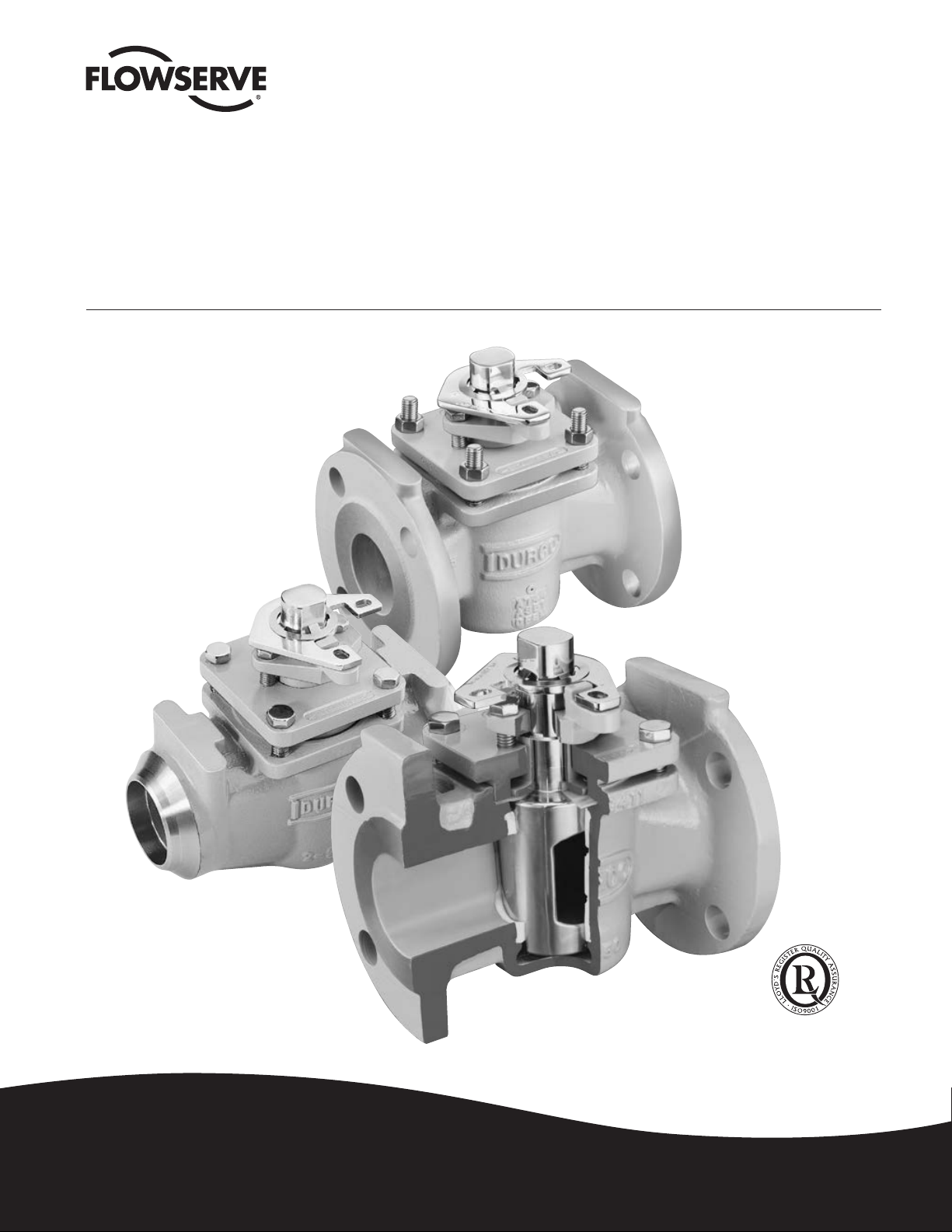
G4, G4ZHF and G4R
Sleeveline® Plug Valves
Non-Lubricated Plug Valves for Chemical Service
Installation
Operation
Maintenance
Experience In Motion
Quality
System
Certificate
FCD DVENIM0240-06
(Bulletin V-240)
Page 2

G4, G4ZHF AND G4R USER INSTRUCTIONS ENGLISH 5-14
FOREWORD
Flowserve Corporation, Flow Control Division, has established
this Installation, Operating and Maintenance Manual to facilitate field installation, operation and repair of G4, G4ZHF and
G4R valves.
It is recommended that questions or concerns involving
the processes described in this manual be directed to the
local Sales Representative of Flowserve Corporation. Only
Flowserve replacement repair parts and assembly tooling
made or designed by Flowserve Corporation should be used.
Part numbers referenced in the following sections are available from Flowserve Corporation, Flow Control Division.
TABLE OF CONTENTS
SECTION TITLE PAGE
FOREWORD
I INSTALLATION INSTRUCTIONS – FLANGED AND WELDED G4, G4ZHF, G4R 2
II OPERATING/MAINTENANCE – G4, G4ZHF, G4R 3
III VALVE DISASSEMBLY – G4, G4ZHF, G4R 4
IV PRESSURE CONTAINING FASTENERS 5–6
V A. VALVE ASSEMBLY – 1/2" & 3/4" G4, G4R 7–8
B. VALVE ASSEMBLY – 1"– 8" G4, G4R 9–11
VI ASSEMBLY SPECIFICATIONS – FIRESAFE VALVES G4Z, G4ZHF, G4ZR 12–14
VII RECOMMENDED SPARE PARTS 15
SECTION I
INSTALLATION INSTRUCTIONS – FLANGED AND WELDED G4, G4ZHF, G4R PLUG VALVES
FLANGED:
Installation of Flowserve flanged valves is best accomplished by
locating valves in pipeline flanges, assuring all corrosion and
foreign materials are removed from pipe flange, and then center
gaskets with the valve flanges. Fastener or taper pins should be
used to align holes and locate gaskets. Fasteners should be
tightened to the corresponding valve and fastener size.
WELDING:
Flowserve Corporation, Flow Control Division recommends
using only qualified welding procedures and personnel for weld
installation of G4R valves.
The following precautions should be observed:
1. The valve should be inspected prior to welding to assure that
no foreign materials obstruct the flow passageway and that the
weld preparation is free of corrosion and physical damage.
2.
The valve should be in the open position while being welded.
Open position is when the flats on the plug stem are parallel with
the pipeline.
3.
The G4R valve contains various sleeve and diaphragm materials
that have a different maximium temperature limitation. Refer to
Table 1.1 for temperature limitations.
4.
The valve body sleeve and diaphragm must not exceed these
tem peratures during welding. This includes preheats, inter passes,
or post weld heat treatments, as applicable. Refer to Figure 11-1
for locations of the sleeve and diaphragm in the center valve
2
section.
5. Welding of the G4R valve without disassembly may be
accomplished with no damage to the sleeve and diaphragm.
Precautions MUST be taken to cool the valve bowl and
monitor temperature. The temperature of the center or bowl
area of the valve must not exceed the listed temperature for the
material. Valves, sizes two inch and smaller, must be wrapped
with water-soaked, fire-resistant material to cool the valve bowl
and inlet where the weld is to be made. Use temperature melt
crayons equal to the sleeve and diaphragm rating to mark
the body welding end and monitor the body temperature.
Thermocouples may be attached to the welding end of the
body, or surface pyrometers may be used to monitor the body
bowl temperature.
CAUTION: DO NOT ALLOW WATER FROM THE SOAKED
WRAPPING MATERIAL TO ENTER THE WELDMENT.
TABLE 1.1
TEMPERATURE LIMITATIONS
MAXIMUM
MATERIAL DESCRIPTION SERVICE
TEMPERATURE
Ultra High Molecular Weight
Polyethylene (UMPE) 200°F (93°C)
Tetrafluoroethylene Polymer (PTFE) 400°F (204°C)
Durlon 2 450°F (232°C)
Duriron Durco 82 (DU-82) 275°F (135°C)
Page 3
G4, G4ZHF AND G4R USER INSTRUCTIONS ENGLISH 5-14
SECTION II
OPERATING/MAINTENANCE INSTRUCTIONS FOR G4, G4ZHF, G4R
Maintenance requirements for G4, G4ZHF and G4R valves
may vary due to operating conditions of the process. Factors
such as operating temperature, pressure, solids content, and
frequency of cycling can influence valve performance and
maintenance requirements.
Seal wear is compensated by adjusting appropriate parts. For
G4, G4ZHF and G4R valves, there are three possible leak paths:
1. Top Cap (bonnet)
2. Stem
3. Line (through)
Corresponding adjustments for each leak path are as follows:
NOTE: Refer to Figure II-1 or Figure VI-1A for parts identification.
1. Top Cap (bonnet)
Leakage due to thermal or pressure cycling is eliminated
by snugging the top cap fasteners (Part 3A) in a “crisscross" pattern. This adjustment is most effective when the
valve is not pressurized. It is important that the top cap
fasteners not be tightened excessively and that torque
values applied be within industry standard for fasteners.
2. Stem
Leakage due to wear of the diaphragm, and/or wear to
the sleeve (primary seal) is eliminated by tightening the
adjuster fasteners (Part 12A) in 1/4 turn increments. It is
recommended that the adjuster fasteners be tightened
evenly.
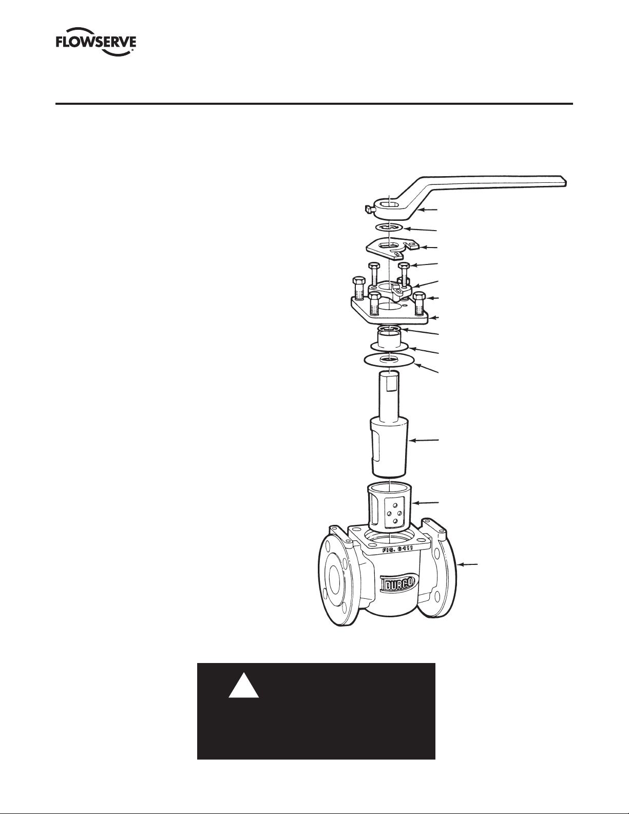
FIGURE II-1
TYPICAL ASSEMBLY OF G4 AND G4R VALVE
WRENCH (13)
STOP COLLAR RETAINER (19A)
STOP COLLAR (19)
ADJUSTER FASTENERS (12A)
ADJUSTER (12)
TOP CAP FASTENERS (3A)
TOP CAP (3)
GROUNDING SPRING (17)
THRUST COLLAR (11)
DIAPHRAGM (6)
PLUG (2)
The valve should be operated between adjustments to
assure that the plug properly seats itself into the sleeve.
If leakage persists after repeated adjustments, the sleeve
and diaphragm will require replacement, as covered in
Section V A and V B or Section VI.
3. Line (through)
Through leakage due to wear of the primary seal can be
eliminated by tightening the adjuster fasteners (Part 12A)
in 1/4 turn increments. It is recommended that the
fasteners be tightened evenly.
The valve should be operated during adjustments to pre-
vent excessive operating torque. Should leakage persist
after repeated adjustments, the sleeve will require replacement, as covered in Section V A and V B or Section VI.
WARNING
!
To avoid personal injury and prevent damage to
equipment, do not operate or repair this valve without
observing the following procedures outlined in this
manual.
SLEEVE (5)
BODY (1)
3
Page 4

SECTION III
VALVE DISASSEMBLY – G4, G4ZHF, G4R
G4, G4ZHF AND G4R USER INSTRUCTIONS ENGLISH 5-14
Recommended Precautionary Measures
1. Valves must be relieved of process fluid and pressure
prior to disassembly.
2. Personnel performing disassembly must be suitably
protected and alert for emission of hazardous process
fluid.
3. If there is a pipe plug located at the bottom bowl of
the valve, DO NOT remove the pipe plug until the valve
plug has been removed.
Disassembly Steps
NOTE: Refer to Figure II-1 or VI-1A for parts identification. If
an actuator or gearbox operates the valve, alignment marks
should be noted to assure correct orientation when reassembled.
This may best be accomplished by making matching marks
on the plug stem and operator housing with no burrs on the
plug stem.
1. Gradually loosen adjuster fasteners (Part 12A) – DO NOT
REMOVE.
2. Turn plug (Part 2) in order to raise the plug to vent any
material trapped in the valve (see note below).
NOTE: If there is no upward movement of the plug
(Part 2), it will be necessary to devise a method of lifting
the plug upward. This may require removal of the valve
operator (Step 3). This operation should be under taken
noting the above precautionary measures. Methods of
plug removal must include protective measures on plug
stem and plug end.
3. WARNING: Do not loosen or remove top cap fasteners
(Part 3A) when removing an operator or accessory.
Remove the operator by un fastening it from the
bracket.
4. Once the plug (Part 2) has lifted, the adjuster fasteners
(Part 12A) can be completely removed.
5. Gradually loosen but DO NOT REMOVE all of the top cap
fasteners (Part 3A). Turn the plug until it is loose from
the sleeve (Part 5) and all pressure has been vented.
(Again, it may be necessary to use a mechan ical means
to move the plug upwards.)
6. Remove the top cap fasteners (Part 3A) and top cap
(Part 3) from the plug stem (Part 2).
7. Remove the plug (Part 2) from the body (Part 1).
8. Remove the grounding spring (Part 17) and thrust collar
(Part 11) from plug stem (Part 2).
9. Remove the diaphragm (Part 6) from plug stem (Part 2).
10. Inspect the valve sleeve (Part 5) for wear or damage,
especially scratches near the top, bottom and port areas.
If wear or damage is excessive, the sleeve should be
replaced.
11. Remove sleeve (Part 5) as follows:
NOTE: Care should be taken not to damage the inter nal
body bore.
a. Using a screwdriver and mallet, cut the old sleeve
through one of the port openings, top and bottom.
b. Grasp the sleeve with a pair of pliers while twisting,
and lift the sleeve from the body.
12. Thoroughly clean all valve parts with an acceptable
cleaner.
13. Inspect parts for damage. Look for marred, scratched or
rough sealing surfaces on the valve plug (Part 2).
NOTE: Reinstallation of damaged or unclean parts will
ruin any replacement seals installed into the valve.
4
Page 5

SECTION IV
PRESSURE CONTAINING FASTENERS
G4, G4ZHF AND G4R USER INSTRUCTIONS ENGLISH 5-14
Material Selection
Selecting the proper fastener material is the ultimate responsibility of the customer because the supplier does not typically
know in what service the valves will be used or what elements
may be present in the environment. Flowserve normally supplies B7 (carbon steel) for ductile cast iron and carbon steel
valves. For stainless steel and high alloy valves, B8 (stainless
steel) fasteners are supplied as standard. All fasteners
used must have a minimum yield strength of 40 000 PSI,
a minimum elongation of 12% and be compatible with the
process fluid. Determining com patibility to the process fluid
goes beyond a material being resistant to general corrosion
because the more important consideration is a material’s
resistance to stress corrosion cracking. Depending on the
service, it may make sense to use B7 fasteners on high alloy
valves. One such service would be marine environments
because of stainless steel’s susceptibility to stress corrosion
cracking in chloride environments. Another key aspect of
fasteners is frequent visual inspection. Because of the common practice of using steel fasteners rather than stainless
steel to avoid chloride stress corrosion cracking, visual
inspection is recommend ed to monitor the general corrosion
of these fasteners. If jacketing or insulation is used on a valve,
CAP SCREWS - STUDS
HHCS - Finished Heavy Hex Head Cap Screw
HCS - Finished Hex Head Cap Screw
STUD - Stud
Dimensions per ASME B18.2.1
it must be periodically removed for visual inspection of the
fasteners. If you wish assistance in determining the proper
fasteners to use, please refer to the attached chart.
Design & Type
The Flowserve valve design standards adopt ASME B18.2.1
(1996) as the standard for fastener type and design. This
national standard requires that finished hex “head” cap
screws be used when the head of the fastener is turned. A
finished hex “head” cap screw and a heavy hex cap screw
have a bearing surface under the head to minimize fric tional
resistance during tightening. They also comply to qualified
body diameters and fully formed head dimen sions. Cookeville
Valve Operation policy is to use finished hex “head” and heavy
hex “head” cap screws for all pres sure retaining fasteners.
This includes top caps, packing adjusters, plug adjusters,
bottom caps, body halves or other pressure retaining components. Compliance is made with ANSI B18.2.2 (1987), Square
and Hex Nuts, when studs and heavy hex nuts are required.
Additional information on these items may be obtained
from the Flowserve Corporation, Cookeville Valve Operation,
Cookeville, Tennessee.
TABLE 1
Alloy identification stamp required on each piece.
Certification required.
Alloy Specification (40 KSI Minimum Yield Strength, 12% Minimum El.)
B840 - Stainless Steel per ASTM A193, Grade B8M2 or B8M3
B7 - Chromium - Molybdenum Alloy Steel per ASTM A193, Grade B7
B7M - Chromium - Molybdenum Alloy Steel per ASTM A193, Grade B7M, 100% hardness tested
B7MT - Chromium Molybdenum Alloy Steel per ASTM A193, Grade B7M, 100% hardness tested, Teflon coated, Dupont SP11C, Type B - Color blue
or green
B8MC2 - Per ASTM A193, Grade B8M (AISI Type 316), Class 2
C20 - Carpenter C20, CB-3 (UNS N08020), ASTM B473, 40 KSI Min. Yield Strength, 12% Min. El.
HC - Hastelloy C276 (UNS N10276), ASTM B574
I625 - Inconel 625 (UNS N006625), ASTM B446
I825 - Incoloy 825 (UNS N08825), ASTM B425, 40 KSI Min. Yield Strength, 12% Min. El.
IN - Inconel 600 (UNS N0660), ASTM B166, 40 KSI Min. Yield Strength, 12% Min. El.
M - Monel (UNS N04400), ASTM B164, Class A or B, 40 KSI Min. Yield Strength, 12% Min. El.
HB - Hastelloy B (UNS 10665), ASTM B335
I718 - Incoloy 718, AMS 5596B, ASTM B637
MKH - Monel K-500, Cold drawn and aged hardened, QQN-286 and ASTM F468
L7 - Chromium-Molybdenum Alloy Steel per ASTM A320, Grade L7
L7M - Chromium-Molybdenum Alloy Steel per ASTM A320, Grade L7M, 100% hardness tested
L7T - Chromium-Molybdenum Alloy Steel per ASTM A320, Grade L7, Teflon coated, Dupont SP11C, Type B - Color green
L7MT - Chromium-Molybdenum Alloy Steel per ASTM A320, Grade L7M, 100% hardness tested, Teflon coated, Dupont SP11C, Type B - Color green
N - Nickel per ASTM B160 (UNS N0220), 40 KSI Min. Yield Strength, 12% Min. El.
B7YC - Chromium-Molybdenum Steel per A193, Grade B7, Yellow Zinc Dichromate Plated
5
Page 6

G4, G4ZHF AND G4R USER INSTRUCTIONS ENGLISH 5-14
SECTION IV
PRESSURE CONTAINING FASTENERS
TABLE 2
NUTS
HN - Finished Heavy Hex Nut
XN - Finished Hex Nut
HXN - Regular Heavy Hex Nut
Dimensions per ANSI B18.2.2
Alloy identification stamp is required on each piece.
Certification required.
8 - 304 Stainless Steel per ASTM A194, Grade 8
8M - 316 Stainless Steel per ASTM A194, Grade 8M
2H - ASTM A194, Grade 2H
2HM - ASTM A194, Grade 2HM
7M - ASTM A194, Grade 7M, 100% hardness tested
7MT - ASTM A194, Grade 7M, 100% hardness tested, Teflon coated, Dupont SP11C, Type B - Color green
M - Monel (UNS N04400), ASTM B164, Class A or B, or QQN-281, Class B
HB - Hastelloy B (UNS N10665), ASTM B335
HC - Hastelloy C276 (UNS N10276), ASTM B574
I625 - Inconel 625 (UNS N06625), ASTM B446
I718 - Incoloy 718, AMS 5596B, ASTM B637
I825 - Incoloy 825 (UNS N08825), ASTM B425
L7 - Chromium-Molybdenum Alloy Steel per ASTM A194, Grade 7
L7M - Chromium-Molybdenum Alloy Steel per ASTM A194, Grade 7M, 235 BHN Max, ASTM A320, Section 9
MKH - Monel K-500, Cold drawn and aged hardened, QQN-286 and ASTM F467
8F - 303 Stainless Steel per ASTM A194, Grade 8F
2HYC - ASTM A194, Grade 2H, Yellow Zinc Dichromate Plated
6
Page 7

G4, G4ZHF AND G4R USER INSTRUCTIONS ENGLISH 5-14
SECTION V
A. VALVE ASSEMBLY – 1/2" & 3/4" G4, G4R
Valve assembly will require usage of a repair tooling kit
that is specific to the size of the valve. These kits can be
obtained from Flowserve FCD, Cookeville, Tenn.
1. Apply Durco® seal 1028B to the inside of the tapered bore
in the body and permit to dry before assembly. RAD-1
material is used for nuclear applications.
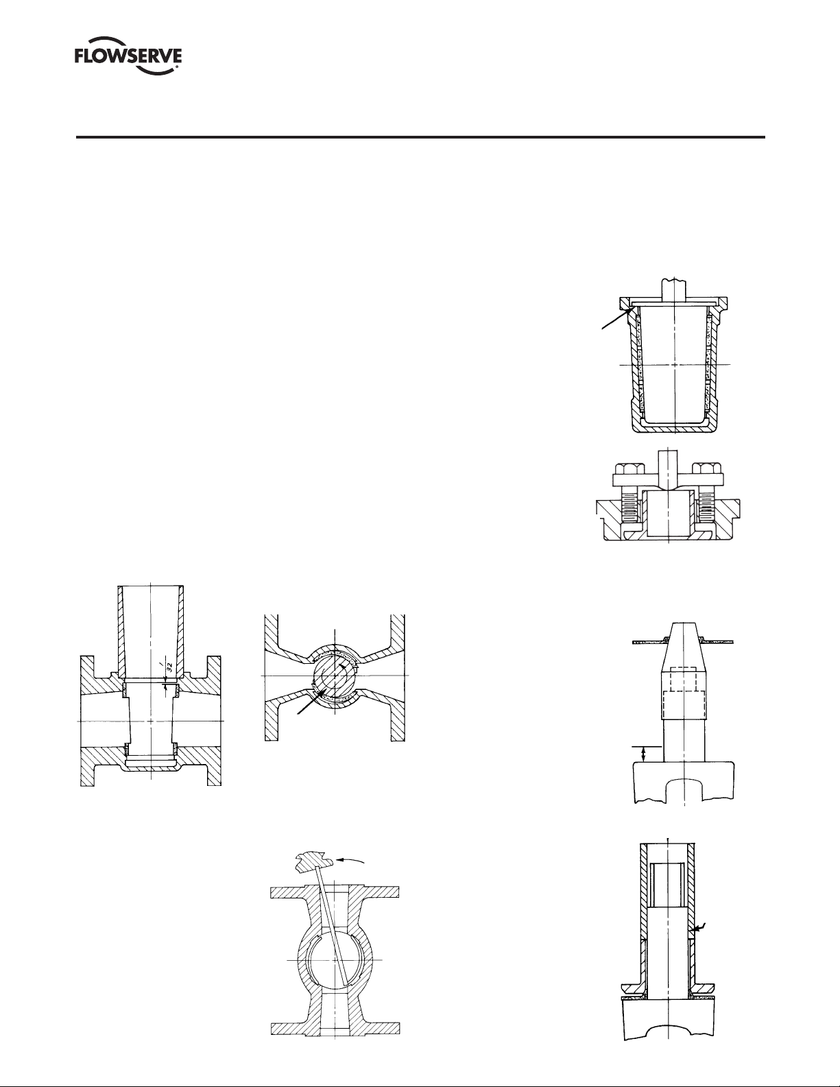
2. Assemble sleeve into body with a coining die, part
#BY81917A. Position coining die so locating pins are
located in bonnet flange holes in body. Position sleeve in
coining die so that sleeve holes are centered over body
ports (Figure V A-1). Place push rod and push rod guide in
coining die and push sleeve into body until push rod stops
on push rod guide (Figure V A-2).
FIGURE V A-1
ASSEMBLE SLEEVE
PTFE SLEEVE
SLEEVE HOLE
CENTERED
OVER BODY
HOLE
COINING DIE
3. Size sleeve. Check sleeve in body to make sure sleeve vent
holes are still centered between body ports. Apply a light
coat of silicone lubricant to sizing Plug #1 and siz ing Plug
#2, part #BY80017B & C. Push sizing Plug #1 into sleeve
until the sizing plug flange bottoms against the counterbore of the valve body. Remove #1 sizing plug and now
push #2 sizing plug in the same manner, but HOLD SIZING
PLUG IN PLACE for 15 SECONDS (Figure V A-3).
1. Rough Size With Plug #1
2. Finish Size With Plug #2 (Hold for 15 Seconds)
FIGURE V A-3
SIZE SLEEVE
SIZING PLUG
FIGURE V A-2
PUSH SLEEVE IN BODY
PUSH ROD
GUIDE
VALVE BODY
PUSH ROD
4. The plug stem and
dia phragm guide are to
be checked for nicks or
burrs before installing
the dia phragm. Nicks
on these surfaces could
result in scratches on
the lip of the dia phragm.
Assemble diaphragm
over plug stem with the
aid of the diaphragm
guide, part #BY77543A,
and assembly tool,
part #BY80019A.
(Figure V A-4).
5. Preassemble the top cap
and adjuster, ad just ing
the cap screws so that
the bottom of the thrust
collar is flush with the
bottom face of the top
cap (Figure V A-5).
FIGURE V A-4
DIAPHRAGM
ASSEMBLY
TOOL
DIAPHRAGM
DIAPHRAGM
GUIDE
1
/2"
ASSEMBLE DIAPHRAGM
ON PLUG
If damaged the
plug taper and ½"
in length of stem
must be repolished
to a surface finish
of 16AA on the
taper and stem.
7
Page 8

G4, G4ZHF AND G4R USER INSTRUCTIONS ENGLISH 5-14
SECTION V
A. VALVE ASSEMBLY – 1/2" & 3/4" G4, G4R
6. Remove thrust collar
from top cap and
as sem ble
over the plug
stem (Figure V A-6).
With the thrust collar
guide, part #BY77545A,
FIGURE V A-5
PRESET ADJUSTER, THRUST
COLLAR AND TOP CAP
SET ADJUSTER CAP SCREWS
TO MAKE ADJUSTER
PARALLEL TO TOP CAP
centering the thrust
collar, force down (with
arbor press) thrust
collar guide to seat the
dia phragm stem seal in
the thrust collar.
7. Place grounding spring
over plug stem, sliding
it down to the thrust
collar.
8. Apply a thin, even film
BOTTOM OF TOP CAP AND
THRUST COLLAR FLANGE
TO BE FLUSH
of silicone or customer-approved lubricant to the entire
surface of the 2° plug taper.
9. Take plug (preassembled with diaphragm, thrust collar
and grounding spring) and place it into body. Using a
soft head mallet, tap
top of plug slightly to
seat plug into sleeve
taper. The plug at this
FIGURE V A-6
SEAT THRUST
COLLAR ON DIAPHRAGM
time will be set ting up
above the body
counter bore ap proximately 1/4". The plug
ports should be lined
THRUST
COLLAR
GUIDE
up in an open posi tion.
10. Place the top cap
assembly over plug
THRUST
COLLAR
and slide it down until
it rests on the thrust
collar.
11. Assemble four
fasteners thru top
cap and body. With
“U” shaped push
plate, part #BY80020A,
resting on the top cap (Figure V A-7), force the top
cap down (with arbor press or pneumatic clamping
arrangement) to seat the top cap against the valve body
counter bore. While holding the cap in this position,
assemble nuts on underside of body flange to a fingertight position against the flange. Coat the fastener
threads with Loctite® 242.
12. Tighten the four top cap fasteners to 7 ft-lb using a
torque wrench. Reference Torque Table #1a & 1b on
page 11.
FIGURE V A-7
TOP CAP ASSEMBLY
PUSH PLATE
NOTE: All fastening
torques are for corro sionfree fasteners and nuts.
Precautions must be
taken not to exceed
recommended fastening
torques.
ASSEMBLE TOP CAP ASSEMBLY
OVER PLUG AND PUSH INTO BODY
13. Loosen the adjuster fasteners to approximately 3/16"
above adjuster. Then rotate the valve plug back and forth
three times, making it rise upward.
14.
Retighten adjuster fasteners to a torque of 10 to 12 in-lb.
The height of the plug port should now be positioned
approximately 1/16" above to flush with the body port.
15. Rotate plug back and forth a couple of times to make
sure the stops and ports line up properly. The final
assembled valve should look similar to Figure V A-8.
16. LEAK TESTING: Any time a valve has been modified in
any manner, including fastener changes, it should be
retested. Normal testing, using gas, should be at 150 PSI
for Class 150 and 300 PSI for Class 300 valves from 1/2"
through 6". It should be noted, how ever, that this test
does not meet the requirements of ANSI, API or MSS.
For test procedures complying with these speci fications,
refer to the appropriate published speci fication.
FIGURE V A-8
ASSEMBLED VALVE
ADJUSTER FASTENER
ADJUSTER
TOP CAP
FASTENER
TOP CAP
BODY
TOP CAP
NUT
PLUG
STOP COLLAR
RETAINER
STOP COLLAR
GROUNDING
SPRING
THRUST
COLLAR
DIAPHRAGM
SLEEVE
8
Page 9
SECTION V
B. VALVE ASSEMBLY – 1"–8" G4, G4R
G4, G4ZHF AND G4R USER INSTRUCTIONS ENGLISH 5-14
Due to the tooling and associated equipment required
(presses, fixtures, etc.) to rebuild 10"–14" size valves, it is highly
recommended
they be returned to the factory or a Flowserve
Authorized Black Tie Valve Rebuilder for repair and rebuild.
Many valves made by Flowserve Corporation handle corrosive
chemicals which may be injurious to property or personnel.
Valves returned without proper attention given to the safety
requirements will be shipped back to the consignor collect.
NOTE: Part number reference is shown in Figure V B-7.
1. Apply Durco seal 1028B to the inside of the tapered bore
in the body and permit to dry before assembly. RAD-1
material is used for nuclear applications.
2. Apply a light coating of oil or silicone to the interior of the
coining die or to the O.D. of the sleeve. Position the sleeve
in the coining die, part series #BY79542A, so that the
diagonal opposite sides of the sleeve port will lock behind
the metal lips in the body (Figure V B-2). The sleeve is then
pushed directly through the coining die into the valve body
until the sleeve drops below the top counterbore of the
valve body (Figure V B-1).
FIGURE V B-1 FIGURE V B-2
Push sleeve directly through coining
die until sleeve drops below top
counterbore of the valve body.
3. A special plug, part series
#BY79664A, containing
A special plug with retractable
or removable blades engages
the two remaining sleeve ports
and pulls them until they fall
behind the body port lips.
DIRECTION OF
ROTARY MOTION
FIGURE V B-2A
Optional assembly operation
for 1" & 11⁄2" G-4 valves
Care must be exercised to
ensure that the bar does not slip
and gouge or tear the sleeve.
retractable or removable
blades is lowered into
the body with the blades
re tracted or removed. The
blades are then installed or
extended and a counterclockwise rotary motion is
applied to the plug engaging
the two remaining diagonal
oppo site sleeve port openings and pulling them until
they fall behind the body port
lips. The plug is then ro tated back to its original position,
and the blades are then removed or retracted. The plug is
then removed from the body (Figure V B-2). In the 1" and
11/2" sizes, a bar may be substituted for the locking plug.
See Figure V B-2A for a description of this operation.
FIGURE V B-3
The sizing plug is pushed
into the sleeve until the
sizing plug flange bottoms
against the counterbore of
the valve body.
4. Apply a thin film of oil on
the sizing plug, part series
#BY79555A, and push it into
the sleeve until the sizing
plug flange bottoms against
the counterbore of the valve
body (Figure V B-3). Allow
the sizing plug to remain in
this position for one minute.
FIGURE V B-4
Thrust collar to be flush with
gasket surface of top cap.
FIGURE V B-5
5. Place the top cap (Part 3)
and adjuster (Part 12) over
the thrust collar. The adjuster
If damaged, the plug taper and
½" in length of stem must be
repolished to a surface finish
of 16AA on the taper and stem.
fasten ers should be threaded
into the top cap until flush
with the bottom (Figure
V B-4).
6. The diaphragm (Part 6) is
as sembled over the plug
stem with the aid of the G4
diaphragm guide, part series
1
/2"
#BY77543A (Figure V B-5)
and #BY79581A. The plug
stem and diaphragm guide
should be checked for nicks
before installing the dia-
FIGURE V B-6
phragm. Nicks on these
surfaces could result in
scratches on the lip of the
dia phragm.
7. The thrust collar is then
assembled over the plug
stem and driven into place
through the use of the thrust
collar guide, part
series
#BY77545A, and an arbor
press (Figure V B-6).
THRUST
COLLAR
GUIDE
9
9
Page 10

SECTION V
B. VALVE ASSEMBLY – 1"–8" G4, G4R
G4, G4ZHF AND G4R USER INSTRUCTIONS ENGLISH 5-14
8. Place the grounding spring (Part 17) over the plug stem.
9. Place the top cap and adjuster over the plug stem. Place
this subassembly into the valve body using an arbor
press to hold the top of the plug flush with the counterbore. (The bottom of the plug ports should be lined up
with the bottom of the body ports.) Push down on the
press until the top cap gasket pad seats firmly against
the body counterbore. Apply thread locking compound
to the threads of the top cap fasteners. Tighten the top
cap fasteners (Part 3A) to a value consistent with industry
standards for size and alloy type. Ref. Torque Table #1a
& #1b on page 11.
10. Remove the valve from the arbor press, loosen the
adjuster fasteners, and operate the plug several times. It
will turn hard at first but will then loosen and turn freely.
11. Tighten the adjuster fasteners (Part 12A) until a
reasonable turning torque (Ref. Table #2 on page 11)
is obtained. The 8" and larger valves are placed in an
oven at 200°F for a minimum of six hours prior to final
adjustment with the plug in the open position. After
removal from the oven and valve has cooled, loosen the
adjuster fasteners. Turn the plug several times. Retighten
the adjuster fasteners until a reasonable plug turning
torque is obtained. The height of the plug port should be
positioned approximately 1/16" above to flush with the
body port.
12. Place the stop collar (Part 19A) and retainer on the plug
stem. The stop collar should point in the direction of flow.
13. The valve is now ready for test and use.
14. LEAK TESTING: Any time a valve has been modified in
any manner, including fastener changes, it should be
retested. Normal testing, using gas, should be at 150 PSI
for Class 150 and 300 PSI for Class 300 valves from 1/2"
through 6". It should be noted, how ever, that this test
does not meet the requirements of ANSI, API or MSS.
For test procedures complying with these speci fications,
refer to the appropriate published speci fication.
PLUG (2)
ADJUSTER FASTENERS (12A)
ADJUSTER (12)
GROUND SPRING (17)
THRUST COLLAR (11)
DIAPHRAGM (6)
STOP COLLAR & RETAINER (19A)
TOP CAP FASTENERS (3A)
TOP CAP (3)
BODY (1)
SLEEVE (5)
BODY,
G4R OR
G4
FIGURE V B-7
ASSEMBLED G4 OR G4R VALVE
10
Page 11

SECTION V
B. VALVE ASSEMBLY – 1"–8" G4, G4R
G4, G4ZHF AND G4R USER INSTRUCTIONS ENGLISH 5-14
Table #1a *Apply Loctite
®
242 to fastener threads, top cap only.
Torque Required on Top Cap Fasteners of Class 150 G4 Valves
VALVE SIZE
MAX. TORQUE (FT-LB) 7 7 7 12 21 31 62 62
Table #1b *Apply Loctite
1
/2–3/4" 1" 11/2" 2" 3" 4" 6" 8"
®
242 to fastener threads, top cap only.
Torque Required on Top Cap Fasteners of Class 300 G4 Valves
VALVE SIZE
MAX. TORQUE (FT-LB) 7 13 13 20 31 62 125 115
1
/2–3/4" 1" 11/2" 2" 3" 4" 6" 8"
Table #2
Torque on Plug Adjusters of G4 Valves, 150# and 300#
VALVE SIZE
MAX. TORQUE (IN-LB) 10 35 35 35 50 80 180 372
Loctite® is a registered trademark of the Loctite Corp.
1
/2–3/4" 1" 11/2" 2" 3" 4" 6" 8"
11
Page 12

G4, G4ZHF AND G4R USER INSTRUCTIONS ENGLISH 5-14
SECTION VI
ASSEMBLY SPECIFICATIONS – FIRESAFE VALVES G4Z, G4ZHF, G4ZR
Note: Part number reference is shown in
Figure VI-1A.
FIGURE VI-1A
TYPICAL ASSEMBLY OF G4Z AND G4ZHF
WRENCH (13)
STOP COLLAR RETAINER (19A)
STOP COLLAR (19)
ADJUSTER FASTENERS (12A)
ADJUSTER (12)
TOP CAP FASTENERS (3A)
TOP CAP (3)
GROUNDING SPRING (17)
THRUST COLLAR (11)
PACKING GRAFOIL® (20)
DIAPHRAGM –
STEEL OR MONEL (6A)
DIAPHRAGM (6)
GASKET GRAFOIL® (21)
O-RING* (22)
PLUG (2)
3. The PFA diaphragm (Part 6)
is to be flared on a tapered
bar just enough to slip over
the plug stem (Figure VI-1).
FIGURE VI-2
Place PFA diaphragm over plug stem
with lip down using the diaphragm
guide.
1
/
2
''
If damaged, the
plug taper and
½" in length of
stem must be
repolished to a
surface finish
of 16AA on the
taper and 63AA
on stem.
5. The metal diaphragm (Part 6A)
is placed over the plug stem
and the hole enlarged just
enough to slip down on the
stem (Figure VI-3).
FIGURE VI-1
Flare PFA diaphragm over
tapered bar.
4. The PFA diaphragm (Part 6)
is placed over the plug
stem with the lip down
using the diaphragm
guide #BY77543A and
#BY79581A (Figure VI-2).
The plug stem should
be checked for nicks
before installing the PFA
diaphragm. Nicks on this
surface could result in
scratches on the lip of
the diaphragm.
FIGURE VI-3
Flare metal diaphragm over
plug stem with lip up.
SLEEVE (5)
PLUG* (2)
BODY (1)
® Grafoil is a registered trademark of Union Carbide Corporation.
*For use on G4Z-HF Alkylation valve.
1
/2"–4"
1. Normal procedures for field replacement of one-piece
sleeves are to be followed for inserting the sleeve,
Section V A (1/2" & 3/4"), steps 1–3 or Section V B (1"–8"),
steps 1–4.
2.
The firesafe top seal assembly differs from the
stan dard G4 top seal and is completed per the following
instructions.
12
FIGURE VI-4
Metal diaphragm is removed and
reassembled with lip down.
6. The metal diaphragm
is then removed and
re placed with the lip down
(Figure VI-4).
7. The Grafoil packing ring
(Part 20) is placed over the
stem (Figure VI-5).
FIGURE VI-5
Grafoil packing ring
placed over stem.
Page 13

G4, G4ZHF AND G4R USER INSTRUCTIONS ENGLISH 5-14
SECTION VI
ASSEMBLY SPECIFICATIONS – FIRESAFE VALVES G4Z, G4ZHF, G4ZR
8. The thrust collar (Part 11)
is then assembled over the
plug stem and driven into
FIGURE VI-6
Packing and thrust collar driven
into place.
place through the use of the
thrust collar guide, part series
#BY77545A, and arbor
press (Figure VI-6).
FIGURE VI-7
Grafoil gasket placed on metal diaphragm using a bonding material.
GASKET
9. The entire assembly
is turned over and the
Grafoil gasket placed on
the metal diaphragm
(Figure VI-7). A small
amount of rubber cement
is placed on the Grafoil
in several
places to cause
it to ad here to the metal
diaphragm.
10. Continue to assemble the valve per Step 8 of Section V A
for the 1/2"–3/4" size valves or Section V B for the 1"–4".
6"– 8"
Due to the tooling and associated equipment required
(presses, fixtures, etc.) to handle 10"–14" size valves, it is
highly recommended they be returned to the factory for repair
and rebuild.
1. Normal procedures for field replacement of one-piece
sleeves are to be followed for inserting the sleeve Section
V B, steps 1–4.
2.
The firesafe top seal assembly differs from the stan dard G4
top seal and is completed per the following instructions.
3. The PFA diaphragm (Part 6) is to be flared on a tapered
bar just enough to slip over the plug stem (Figure VI-1).
4. The PFA diaphragm is placed over the plug stem with the
lip down (Figure VI-2). The plug stem should be checked
for nicks before installing the PFA diaphragm. Nicks on
this surface could result in scratches on the lip of the
diaphragm.
5. The thrust collar (Part 11) and thrust collar guide, part
series #BY77545A, are to be installed over the plug stem
and loaded by an arbor press to flatten the PFA firesafe
diaphragm. Remove the thrust collar and thrust collar
guide.
6. The metal diaphragm (Part 6A) is placed over the plug
stem and the hole enlarged just enough to slip down on
the stem (Figure VI-3).
7. A thin coat of silicone oil is applied to the down edge of
the metal diaphragm. The diaphragm is then placed over
the plug stem with the lip down (Figure VI-4).
8. The Grafoil packing ring (Part 20) is placed over the stem
(Figure VI-5).
9. The thrust collar (Part 11) is then assembled over the
plug stem and driven into place through the use of the
thrust collar guide and arbor press (Figure VI-6). Place
the plug (Part 2) into the body in the open position.
10. The Grafoil top cap gasket (Part 21) is to be installed
with the tapered or small edge diameter down or placed
against the valve counterbore. The plug is pushed down
until it is flush with the bottom of the body port in order
to check the diaphragm fit inside the Grafoil gasket for
clearance. The PFA diaphragm must not ride on the
Grafoil gasket but should fit just inside the Grafoil.
11. The top cap (bonnet) (Part 3) and adjuster assembly is
installed and the plug is pushed down in the open position again until the bottom of the port is flush with the
body part and the top cap bottoms firmly on body counterbore. The top cap must be checked before installation
to ensure there is no chamfer on outside edge of the cap.
The inside edges are to have a break corner chamfer only.
12. The top cap is visually located to be evenly spaced inside
the body counterbore. The side of the top cap compression flange is equally spaced with the side wall of the
body counterbore. Fasteners should be installed and
tightened to 5 ft-lb torque to prevent movement of the
cap during initial torquing.
13. While continuing to hold the open plug in a flush condi-
tion with the body, the top cap fasteners (Part 3A) are
torqued in 50 ft-lb increments. Tighten in a crisscross
method to
the following values using a calibrated torque
wrench. The adjuster fasteners (Part 12A) are completely
loosened for this step.
Size Torque
6" 125 ft-lb
8" 115 ft-lb
14. The top cap (Part 3) is then relieved from compression
and removed. The Grafoil gasket (Part 21), PFA
diaphragm (Part 6), metal diaphragm (Part 6A) and
Grafoil packing ring (Part 20) are visually checked for
misalignment.
13
Page 14

G4, G4ZHF AND G4R USER INSTRUCTIONS ENGLISH 5-14
SECTION VI
ASSEMBLY SPECIFICATIONS – FIRESAFE VALVES G4Z, G4ZHF, G4ZR
15. Care must be taken when lifting the packing ring/metal
diaphragm as to prevent damage or wrinkling to the sealing areas of the diaphragm. Should the metal diaphragm
be wrinkled in the sealing area, the top cap is to be
reworked for flatness and surface finish. The diaphragm
is to be replaced and repeat steps 11 through 13.
16. Slight flare up of 1/16" on the outer diameter edge of the
metal diaphragm is permitted but if excess bending
occurs, the metal diaphragm must be custom fitted to
the body counterbore while located on the plug stem.
17. Uneven gasket compression to the Grafoil (Part 21) or
PFA diaphragm gasket (Part 6) is cause for rejection and
replacement of those parts.
18. Once it has been determined that the gaskets fit properly,
the top cap (Part 3), grounding spring (Part 17), and
thrust collar assembly (Part 11) are reinstalled and steps
11 through 13 are repeated. Continue to tighten the top
cap fasteners in 50 ft-lb increments in a crisscross fashion to the levels found in Table #1a & 1b on page 11.
NOTE: All fastening torques are for Loctite® coated, corro-
sion-free fasteners and nuts. Extreme care must be taken
to prevent overstressing fasteners and sub sequent valve
parts by fastening in excess of industry standards for
appropriate size and alloy fasteners. Ref. Torque Table
#1a & 1b on page 11.
19. The plug is turned a minimum of three times and the
sleeve is checked on all four seal zones for tears.
20. With the plug in the open position, adjuster fasteners
(Part 12A) are then torqued to the following levels: Ref.
Table #2. The height of the plug port should be positioned
approximately 1/16" above, to flush with the body port.
Size Torque
6" 15 ft-lb
8" 31 ft-lb
21. Operate the plug a minimum of three times.
22. The gear box or actuator is installed with the plug set in
the open position, and the adjusting screw is then locked.
Careful attention is required to set the gear box stop
screw at 90° rotation for the closed position. A protractor
may be used to check for 90° rotation or alignment
scribes may be noted on the gear box cover.
Selection, Installation, Operation and Maintenance
Flowserve Corporation has established industry leadership in the design and
manu fac ture of its products. When properly select ed, each product is designed to
perform its intended function safely during its useful service life. However, it is
necessary that Flowserve customers be fully aware of their responsi bilities when
using these products.
Each Flowserve valve product may be used in numerous applications under
a wide variety of industrial service conditions. Although Flowserve can, and often
does, provide general guide lines, it is obviously not possible to provide application-
specific data and warnings for all conceivable applications. The purchaser/end user
must therefore assume the ultimate responsibility for the proper selection, installation, operation and main tenance of the products. Read the appropriate IOM before
installation, operating or repairing any valve. The purchaser/end user should train
its employees and/or contractors in the safe use of the Flowserve products in
connection with the purchaser’s manufac turing processes.
Flowserve will continue to provide its customers with the best possible products
and service available. We do not recommend substituting surplus or remanufactured valves over new Durco valves or those repaired in an authorized service center.
Should you have any questions about these provisions or about Flowserve products
in general, please contact your local Flowserve valve representative, who will be
happy to help.
14
Page 15

G4, G4ZHF AND G4R USER INSTRUCTIONS ENGLISH 5-14
SECTION VII
RECOMMENDED SPARE PARTS
Named parts shown below by respective valve are recommended
spare parts for that valve model.
GROUND SPRING
DIAPHRAGM
SLEEVE
G4 VALVE
Design, Manufacture, and In-house Repair
of Ball, Butterfly and Plug Valves
in Cookeville, TN
® Krytox is a registered trademark of DuPont.
15
Page 16

G4, G4ZHF AND G4R USER INSTRUCTIONS ENGLISH 5-14
Selection, Installation, Operation and Maintenance
Flowserve Corporation has established industry leadership in the design and manufacture of its products. When
properly selected, each product is designed to perform its intended function safely during its useful service life. However,
it is necessary that Flowserve’s customers be fully aware of their responsibilities when using these products.
Each Flowserve valve product may be used in numerous applications under a wide variety of industrial service conditions. Although Flowserve can, and often does, provide general guidelines, it is obviously not possible to provide application
specific data and warnings for all conceivable applications. The purchaser/end user must therefore assume the ultimate
responsibility for the proper selection, installation, operation and maintenance of the products. Read the appropriate IOM
before installation, operating or repairing any valve. The purchaser/end user should train its employees and/or contractors
in the safe use of the Flowserve products in connection with the purchaser’s manufacturing processes.
Flowserve will continue to provide its customers with the best possible products and service available. We do not recommend substituting surplus or remanufactured valves over new Durco valves or those repaired in an authorized service center.
Should you have any questions about these provisions or about Flowserve’s products in general, please contact your local
Flowserve valve representative, who will be happy to help.
Or Consult Your Local Stocking Distributor
For more information, contact:
Flowserve Corporation
Flow Control Division
1978 Foreman Drive
Cookeville, Tennessee 38501
Phone: 931 432 4021
Fax: 931 432 3105
www.flowserve.com
Flowserve Ahaus GmbH
Von Braun Straße 19a
D-48683 Ahaus
Germany
Phone: +49 2561 686-0
Fax: +49 2561 686-39
Flowserve Pte. Ltd.
12 Tuas Avenue 20
Republic of Singapore 638824
Phone: 65 862 3332
Fax: 65 862 2800
FCD DVENIM0240-06
(Bulletin V-240)
May 2014
© 2014 Flowserve Corporation
 Loading...