

Page 1
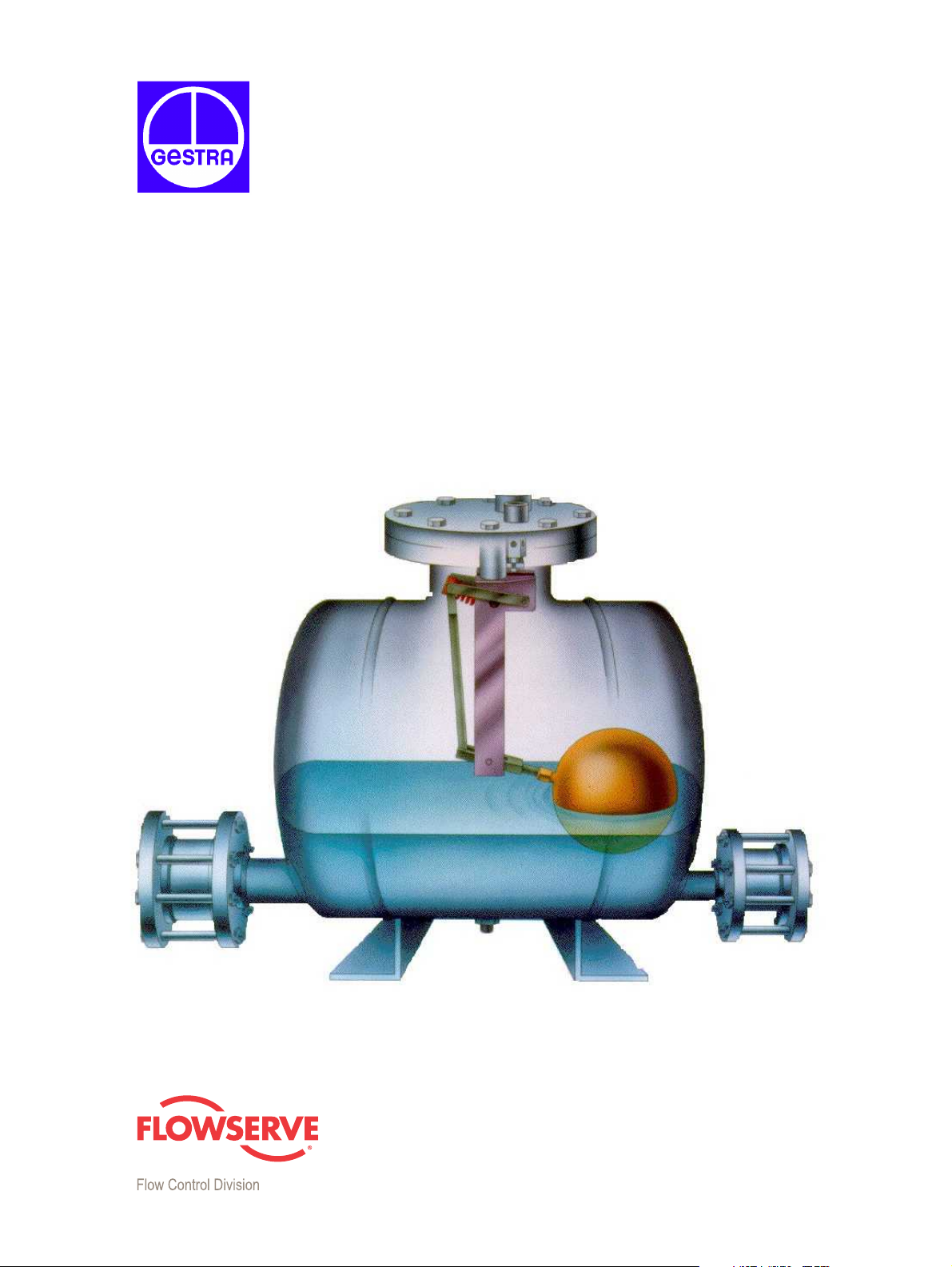
Gestra FPS 14
INSTALLATION
&
MAINTENANCE MANUAL
Page 2
Operation
Maximum operating pressure: 150 psig
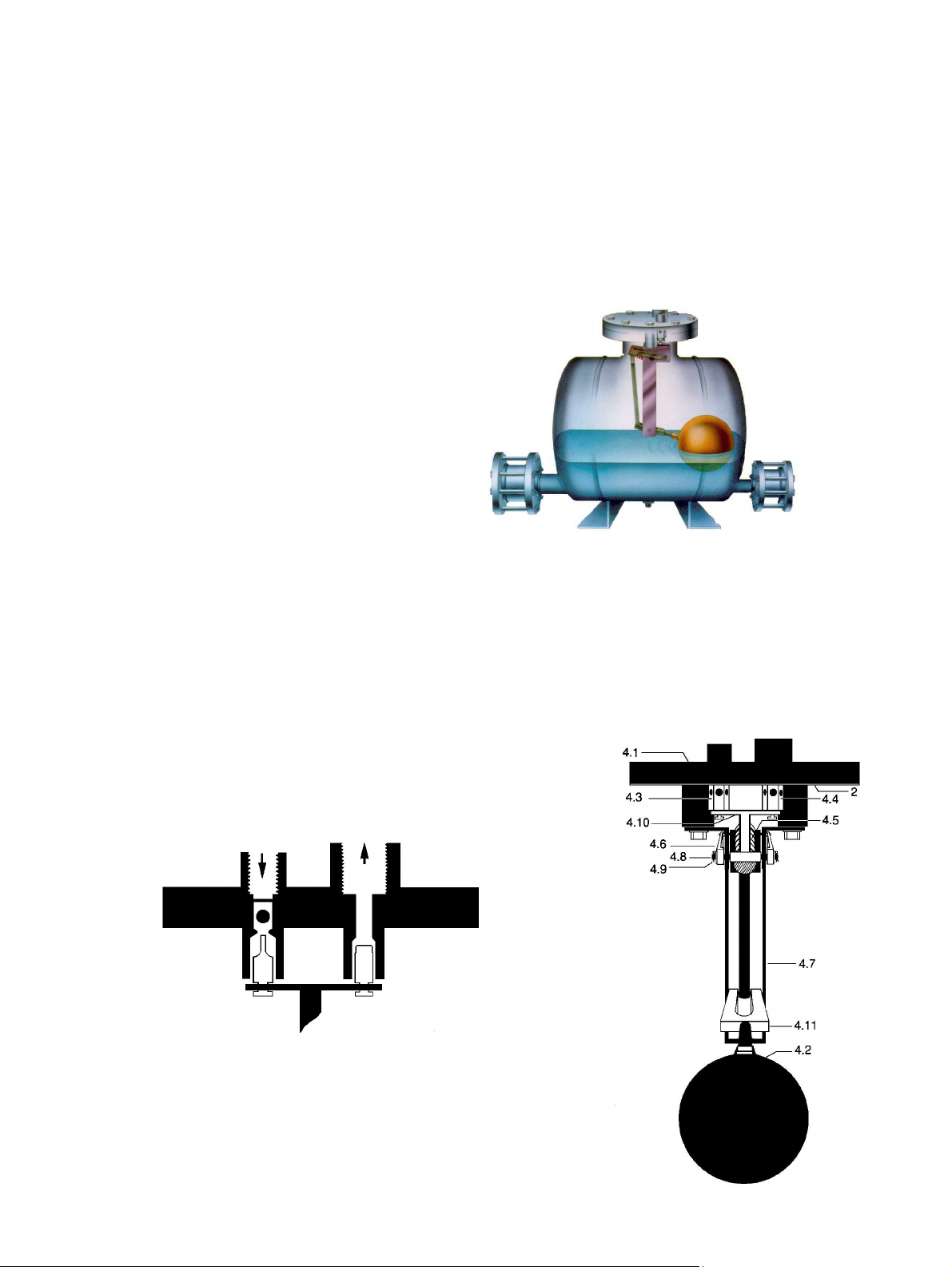
1. At the beginning of the cycle, the float ball
(4.2) is at its lowest position. The vent
valve (4.4) is open and the pressure valve
(4.3) is closed.
2. The liquid to be pumped enters the pump
tank by gravity through the inlet check
valve. As the pump fills, the float ball (4.2)
rises. The outlet check valve prevents back
flow of liquid into the pump tank from the
downstream side.
3. At the high trip point the mechanism
snaps over center. The compressed coil
spring (4.5) simultaneously closes the vent
valve (4.4) and opens the pressure valve (4.3). The motive gas flows through the pressure valve
(4.3) and pushes the liquid out of the pump tank though the outlet check valve. The inlet check
valve prevents liquid from flowing back into the upstream piping.
4. As the liquid falls, the float ball (4.2) drops. At the low trip point, the mechanism snaps over
center and the compressed coil spring (4.5) simultaneously opens the vent valve (4.4) and
closes the pressure valve (4.3). The pump tank depressurizes as the motive gas is relieved
through the vent valve.
5. After the pressure in the pump tank is relieved through the
vent valve (4.4), flow resumes through the inlet check valve
and a new cycle begins.
Page 3
Installation
Consult the Installation Drawings for the proper piping configuration for your application.
Please call GESTRA if you are not sure of the
proper configuration.
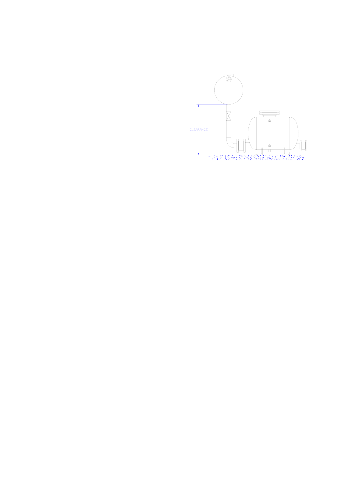
1. CLEARANCE: Install the pump below the
equipment to be drained. Proper clearance is
required for the pump to fill. The clearance is
the distance between the base of the pump
and the bottom of the equipment to be
drained. The FPS 14 and FPS 23 require a
minimum clearance of 36”.
2. CHECK VALVES: Install the check valves on
the pump tank, with gaskets, making sure the
check valves are installed in the same
direction. The flow direction has been stamped on each check valve and should match the flow
arrow on the front of the tank.
a. Install lower flange bolts and secure with nuts and lock washers.
b. Place the check valve between the flanges from above onto the bottom bolts. Verify the
flow arrows are pointing in the correct direction.
c. Install and center the gaskets on both sides of the check valves.
d. Install the remaining flange bolts, nuts, and lock washers. Tighten evenly in a star pattern.
NOTE: The correct bolts for the different check valves are as follows:
1” RK16A (S.S.) 1/2”-13x3-1/2” (FPS-366)
1” RK44 (Bronze) 1/2”-13x3” (FPS-193)
2” RK16A (S.S.) 5/8”-11x4-1/2” (FPS-313)
2” RK44 (Bronze) 5/8”-11x6” (FPS-034)
3” RK16A (S.S.) 5/8”-11x6” (FPS-034)
3” RK44 (Bronze) 5/8”-11x5” (FPS-071)
e. Connect piping from discharge check valve flange to the condensate return line or other
discharge point
Full Port Isolation Valves are recommended on the pump inlet and outlet to allow the pump to
be isolated for service.
Pressure Gauges are recommended upstream and downstream of the pump for accurate
measurement of actual operating conditions.
NOTE: All isolation valves must be full port in order to achieve rated pump capacity.
3. MOTIVE GAS SUPPLY: Connect the motive gas supply (steam, air, or gas) to the ½” NPT
connection “P” on the top of the cover flange. The motive gas supply line should have a
strainer and a steam trap (GESTRA MK series for steam service) or liquid drainer trap (GESTRA
UNA series for air or gas service) installed before the pump. See installation drawings for the
proper piping of the components for the motive supply.
A Pressure Gauge should be installed on the motive gas supply to verify that there is sufficient
motive gas pressure at the pump. If steam is being used, a siphon loop (pigtail) should be
installed before the pressure gauge.
Page 4

A Full Port Isolation Valve should be installed on the motive gas supply line to allow the pump
to be isolated for service.
A Union or Flange should be installed between the isolation valve and the pump mechanism to
allow for easy removal of the mechanism for service. This should be installed 14” or more
above the cover flange, or in a horizontal plane outside of the O.D. of the cover flange, for easy
removal.
NOTE: Motive gas pressure should be reduced to the minimum required to both overcome
back pressure and high enough to provide necessary pump capacity.
NOTE: If the motive gas pressure exceeds 200 psig, a pressure-reducing valve (PRV) must be
installed on the motive gas supply line to reduce the pressure to the pump. The PRV should be
installed as far upstream as possible for optimum performance.
A Safety Relief Valve set at or below 200 psig, and a pressure gauge should be installed on the
motive gas supply line to protect the pump should the PRV fail. These items should be installed
downstream of the PRV, and upstream of the pump.
4. RESERVOIR / VENTED RECEIVER TANK: A reservoir or vented receiver tank is always required
ahead of the pump. This is to prevent equipment flooding while the pump is in the discharge
cycle. The actual requirement depends on the application and the type of installation. Please
consult GESTRA if a reservoir or vented receiver is not existing, or has not been specified.
5. VENT LINE: Connect the vent line to the 1” NPT vent connection “V”. This vent line should be
pipe to atmosphere, or back to the equipment to be drained. Application details will determine
how the vent must be piped.
A Tee and Ball Valve should be installed in the vent line for troubleshooting purposes (See
Installation Drawings). This is very important because it will allow troubleshooting of the vent
and pressure valves without removing the mechanism from the tank.
A full port isolation valve should be installed on the vent line to allow the pump to be isolated
for service.
A Union or Flange should be installed between the isolation valve and the pump mechanism to
allow for easy removal of the mechanism for service. This should be installed 14” or more
above the cover flange, or in a horizontal plane outside of the O.D. of the cover flange, for easy
removal.
If the vent line piping needs to be run more than 10 feet, the pipe size should be increased to
greater than 1” in order to prevent restrictions which could reduce the capacity of the pump.
If the vent line is run horizontally, the piping should be pitched so as to be self-draining to
prevent vapor lock.
NOTE: If condensate pressure from the equipment to be drained can exceed pump outlet
pressure under normal operating conditions, a steam trap must be installed after each pump.
This steam trap will prevent steam from blowing though the pump and entering the condensate
return line. Consult GESTRA for the proper steam trap sizing and selection.
Page 5

Maintenance
Turn off the motive gas pressure (steam, air, or gas). Close all isolation valves, and relieve the
pressure in the pump by opening the ½” NPT drain plug on the bottom of the tank, or one of the
two (2) ¼” NPT pipe plugs on the top of the cover flange. Remove the bolts from the mechanism
cover and lift the mechanism from the tank. A clearance of fourteen (14) inches is required to
remove the mechanism from the tank.
1. Be sure the mechanism is completely free of dirt and scale, and moves freely.
Remove any obstructions. Make sure the mechanism snaps at the top and the bottom of the
stroke. Check the integrity of the pivot and cotter pins.
2. Check the float ball for damage, pinholes, or water logging.
If the float ball is full of water, is cracked, or will not float it must be replaced.
If the float ball floats properly, it can be reinstalled on the mechanism.
3. With the float ball in the raised position (closest to the cover flange), check for an air gap
under the striking pin. There should be 1/16” or more clearance below the striking pin. If there
is no air gap under the pin, this is an indication that the valves may be worn.
4. Check the spring.
If the spring is broken or defective, it must be replaced.
To replace the spring, remove the float ball. Remove pivot pins #1 and #2 in that order. This
will free the spring for removal and replacement. After the new spring is in place, reinstall pivot
pin #2, using the float arm for leverage to compress the spring. After pivot pin #2 is in place,
reinstall pivot pin #1 and the float ball.
After the spring has been replaced it is important to recheck the air gap, as explained in step
#3 of the MAINTENANCE section. A proper air gap indicates that all of the components have
been reinstalled correctly.
PIN #2
AIR GAP
PIN #1
BOLT
Page 6

5. Check the vent and pressure valves for damage or blockage.
To check these valves the mechanism must be removed from the cover flange by unscrewing
the two (2) bolts from the sides of the support structure. Lift the entire mechanism until it
becomes free from the flange. Remove the valves and inspect them for damage.
If the valves are in good condition, clean and reinstall them on the cover flange.
If a blockage exists and can be removed without damaging the valves, clean the valves and
reinstall them on the cover flange. If the blockage was found in the pressure valve, inspect and
clean the strainer on the pressure supply line. If there is no strainer installed, install one
upstream of the pressure supply connection.
If any of the valve components are damaged the entire valve assembly must be replaced.
NOTE: when replacing the vent and pressure valves it is important that the valves are properly
matched. The vent has a flat head and the supply valve has a tapered head with a check ball
inside of the body.
Start-Up
1. Slowly open the motive gas (stem, air, or gas) supply valve to the pump. Make sure that there is
adequate pressure to the pump, and that the steam trap (steam) or liquid drainer (air or
pressurized gas) is working properly.
2. Open any isolation valves on the vent, condensate outlet and inlet, in that order. This should
allow liquid to begin flowing into the pump. The pump will discharge when the tank is nearly
full.
NOTE: For low liquid flow rates, the pump may take several minutes before it cycles.
3. If the pump does not seem to be operating properly, recheck the installation and restart the
start-up procedure. If the pump is still not working correctly, follow the Troubleshooting
procedures in this manual.
Page 7

Troubleshooting
PROBLEM – Pump will not fill or is slow to fill
1. Are all of the isolation valves open?
Check the isolation valves on the pump inlet and vent. If these are closed, open the valves and
check for proper pump operation. Check all strainer screens for obstruction. Clean the strainers
if necessary and check for proper pump operation.
2. Is there sufficient clearance?
The clearance is the distance between the base of the pump
and the bottom of the equipment to be drained. The FPS 14
and FPS 23 require a minimum clearance of 36” to fill properly.
Verify the clearance, lower the pump or raise the equipment if
there is insufficient clearance. Consult GESTRA if this is not
possible.
3. Are the check valves installed in the proper direction?
Make sure the flow arrows on both of the check valves are in the same direction and match the
flow arrow on the pump tank. If the check valves are installed incorrectly, reinstall properly and
check for proper pump operation.
4. Are the check valves working properly?
There are two possible problems:
a.) The inlet check valve is stuck closed.
b.) The outlet check valve is stuck open.
i.) If the inlet check valve is stuck closed, condensate will not be able to fill the tank.
To check the inlet check valve it must be removed from the line.
ii.) If the outlet check valve is stuck open, the condensate from the down stream side
will re-enter the pump tank. To verify this, close the outlet isolation valve. If the
pump begins to fill properly the outlet check valve could be stuck partially or
completely open.
If there appears to be a check valve problem, remove them from the pump. Check for any
debris or foreign matter blocking the check valve. Make sure that the check valve disc is not
canted or cocked. Push the disc with your finger, it should move freely and return to the closed
position. You will feel some resistance from the check valve spring when pushing the disc.
If the check valve(s) are good reinstall them and check for proper pump operation.
If the check valve(s) are damaged they must be replaced or repaired.
5. Is the pump cycling?
Listen to the pump. During the proper operation of the pump, each complete cycle should be
noted by two (2) audible sounds. If a Gauge Glass is installed, check to see if the liquid level is
rising and falling. A Cycle Counter or Pressure Gauge will also indicate whether or not the
pump is cycling.
NOTE: If the condensate load is very low when the pump is being check, it would not be
unusual to have to wait for several minutes to verify proper pump operation.
If it is determined that the pump is not cycling, the mechanism must be removed from the tank
and inspected. See MAINTENANCE Instructions.
Page 8

6. Check the operation of the Vent and Pressure valves.
CAUTION: At the end of each pumping cycle, when the vent valve first opens, there will be a
puff of motive gas (Steam, air, or gas) as the tank is depressurizing. This is normal and should
not be mistaken for a leaking pressure valve. Be careful when troubleshooting, and only put
your hand near the vent after the initial puff disappears.
a.) Close the isolation valve on the vent line. If a ball valve has been installed on a tee in the
vent line, open the valve. If not, detach the vent line so that it is open to atmosphere.
b.) When the pump is in the filling cycle, the vent valve should be open and there should be a
flow of gas from the vent. This is the pump contents being evacuated as the liquid fills the
pump tank. If there is no flow of gas from the vent then the vent valve either has not
opened or has a blockage. The mechanism will have to be removed from the tank and
inspected to resolve this problem. See MAINTENANCE Instructions.
c.) If the full motive gas pressure is found at the vent, this indicated either that the pressure
valve is not closed, or that there is a leak in the pressure valve. If this is the case, close and
re-open the isolation valve on the pressure supply line. This may dislodge any debris. If
there is still full motive gas pressure at the vent or the pump still will not fill properly, the
mechanism must be removed from the tank and inspected. See MAINTENANCE
Instructions.
d.) Closed System: If the pump begins to fill when the vent valve is open to atmosphere and
stops when the vent line is reconnected to the return tank, then the pump is vapor locked.
A thermostatic air vent must be installed on the vent line at the highest point, and the vent
line must be self-draining.
PROBLEM – Pump will not properly discharge the condensate after filling
1. Are all of the isolation valves open?
Check the isolation valves on the pump outlet and motive supply line. If these are closed, open
the valves and check for proper pump operation. Check all strainer screens for obstruction.
Clean the strainers if necessary and check for proper pump operation.
2. Is there motive gas pressure (steam, air, or gas) to the pump?
Verify that all pressure supply valves are open, and that there is pressure at the motive gas
supply inlet.
If there is no motive gas pressure, check the motive gas supply system and pressure valve for
clogging.
3. Is the motive gas pressure (steam, air, or gas) high enough for proper operation?
The motive gas pressure must be high enough to overcome the backpressure after the pump
and high enough to provide the required pumping capacity. If there is not a pressure gauge
installed on the outlet of the pump, the backpressure can be measured during the pumping
cycle by installing a pressure gauge in the ¼” NPT connection on the top of the cover flange.
The pressure in the tank during the pumping cycle is approximately 2 – 3 psig higher than the
backpressure. If the pump tank pressure equals the motive gas pressure, the motive gas
pressure is not high enough to overcome the backpressure on the pump.
If the motive gas pressure is not high enough to overcome the backpressure then increase the
motive gas pressure.
Page 9

4. Are the check valves installed in the proper direction?
Make sure the flow arrows on both of the check valves are in the same direction and match the
flow arrow on the pump tank. If the check valves are installed incorrectly, reinstall properly and
check for proper pump operation.
5. Are the check valves working properly?
There are two possible problems:
c.) The inlet check valve is stuck closed.
d.) The outlet check valve is stuck open.
iii.) If the inlet check valve is stuck closed, condensate will not be able to fill the tank.
To check the inlet check valve it must be removed from the line.
iv.) If the outlet check valve is stuck open, the condensate from the down stream side
will re-enter the pump tank. To verify this, close the outlet isolation valve. If the
pump begins to fill properly the outlet check valve could be stuck partially or
completely open.
If there appears to be a check valve problem, remove them from the pump. Check for any
debris or foreign matter blocking the check valve. Make sure that the check valve disc is not
canted or cocked. Push the disc with your finger, it should move freely and return to the closed
position. You will feel some resistance from the check valve spring when pushing the disc.
If the check valve(s) are good reinstall them and check for proper pump operation.
If the check valve(s) are damaged they must be replaced or repaired.
6. Is there water in the vent line?
A small amount of water is caused by the condensation of the venting motive gas and is not an
indication of a problem.
If a large amount of water is present in the vent line, there are two (2) possible problems:
a.) The mechanism has “hung up”.
b.) The float ball has collapsed.
Either problem would keep the mechanism from snapping at the top trip point, preventing the
pump from discharging condensate. If this is the case the mechanism will have to be removed
from the pump tank and inspected. See Maintenance Instructions.
7. Is the pump cycling?
Listen to the pump. During the proper operation of the pump, each complete cycle should be
noted by two (2) audible sounds. If a Gauge Glass is installed, check to see if the liquid level is
rising and falling. A Cycle Counter or Pressure Gauge will also indicate whether or not the
pump is cycling.
NOTE: If the condensate load is very low when the pump is being check, it would not be
unusual to have to wait for several minutes to verify proper pump operation.
If it is determined that the pump is not cycling, the mechanism must be removed from the tank
and inspected. See MAINTENANCE Instructions.
8. Check the operation of the vent and Pressure valves.
CAUTION: At the end of each pumping cycle, when the vent valve first opens, there will be a
puff of motive gas (Steam, air, or gas) as the tank is depressurizing. This is normal and should
not be mistaken for a leaking pressure valve. Be careful when troubleshooting, and only put
your hand near the vent after the initial puff disappears.
Page 10

a.) Close the isolation valve on the vent line. If a ball valve has been installed on a tee in the
vent line, open the valve. If not, detach the vent line so that it is open to atmosphere.
b.) When the pump is in the filling cycle, the vent valve should be open and there should be a
flow of gas from the vent. This is the pump contents being evacuated as the liquid fills the
pump tank. If there is no flow of gas from the vent then the vent valve either has not
opened or has a blockage. The mechanism will have to be removed from the tank and
inspected to resolve this problem. See MAINTENANCE Instructions.
c.) If the full motive gas pressure is found at the vent, this indicated either that the pressure
valve is not closed, or that there is a leak in the pressure valve. If this is the case, close and
re-open the isolation valve on the pressure supply line. This may dislodge any debris. If
there is still full motive gas pressure at the vent or the pump still will not fill properly, the
mechanism must be removed from the tank and inspected. See MAINTENANCE
Instructions.
d.) Closed System: If the pump begins to fill when the vent valve is open to atmosphere and
stops when the vent line is reconnected to the return tank, then the pump is vapor locked.
A thermostatic air vent must be installed on the vent line at the highest point, and the vent
line must be self-draining.
PROBLEM – Chattering or Banging in condensate return line after pump has discharged
1. Are the multiple rises and drops after the pump discharge?
If so, install a vacuum breaker on the highest point in the return line. For a closed system install
an air vent downstream of the vacuum breaker.
2. Does the condensate inlet pressure to the pump exceed the condensate return line pressure?
If so, this indicates the probability that live steam is blowing through the pump.
Page 11

Installation of Optional Accessories
Cycle Counter
The cycle counter is installed by screwing the pneumatic cylinder into one of the ¼” NPT
connections on top of the cover flange. The force of the pressurizing gas lifts the counter
arm for each cycle.
Freeze Protection Drain Valve
If the pump is to be installed outside, or anywhere that freezing is a threat, a Freeze
Protection Drain Valve should be installed on the ½” NPT drain connection on the bottom
of the tank. A pipe should be installed after the drain valve so that the discharge is visible.
See the instructions provided with the valve for more detailed installation directions.
Gauge Glass Assembly
2 Valves, 2 Rods, 1 Glass, 2 ¾” NPT Short Nipples, and 2 ¾” NPT Unions
This assembly is installed on the two (2) ¾” NPT connections on the front of the tank. The
valve with the drain connection must be installed in the bottom connection. The ¾” short
nipples and unions are threaded into the top and bottom tank connections. The valve is
threaded into the mating part of the ¾” union. It is very important that the top and bottom
valves line up before the glass is installed, or else the glass will break. The glass is installed
into the bottom valve, and the top valve is fitted over the top of the glass, and the union is
tightened. Tighten the two (2) fittings that hold the glass and install the guard rods.
Insulation Blanket
Wrap the main blanket piece around the pump tank so that the opening is on the same
side as the two (2) ¾” NPT couplings on the front of the tank. Fasten the front seam and
the two (2) end pieces, (if required) using the supplied stainless steel wire.
Pressure Gauge
Install the pressure gauge, with the syphon loop (pigtail), in one of the ¼” NPT connections
on the top of the cover flange.
Pressure Reducing Valve
The PRV must be installed upstream of the pump mechanism on the motive gas supply line.
The pressure must be regulated below 200 psig, unless a special tank has been ordered. See
the instructions provided with the valve for more detailed installation instructions.
Safety Relief Valve
A safety relief valve set at or below 200 psig, and a pressure gauge should also be installed
between the PRV and the pressure valve connection on to of the cover flange. This will
protect the pump in case the PRV fails. See the instructions provided with the valve for
more detailed installation instructions.
®
GESTRA GmbH
Postfach 10 54 60
D-28054 Bremen
Hemmstraße 130
D-28215 Bremen
Tel. +49 (0) 421 35 03 - 0
Fax +49 (0) 421 35 03- 393
E-mail
gestra.gmbh@gestra.de
Internet www.gestra.de
An Invensys company
A Unit of Flowserve Corporation
 Loading...