

Page 1

EV 30
Installation Instructions 810496-00
Bottom Loading and Unloading System EV 30
1
Page 2

2
Page 3
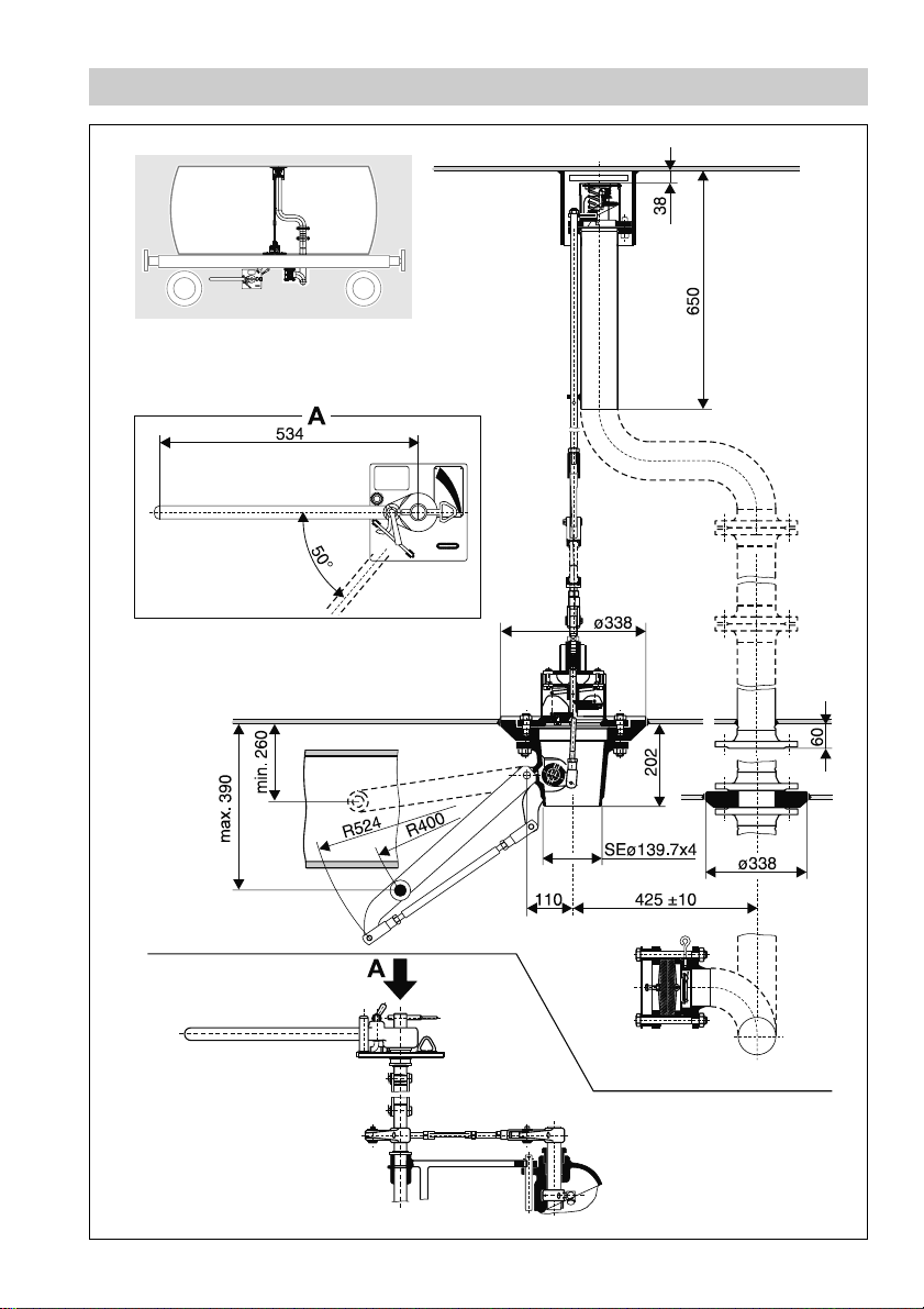
Dimensions
Fig. 1
3
Page 4
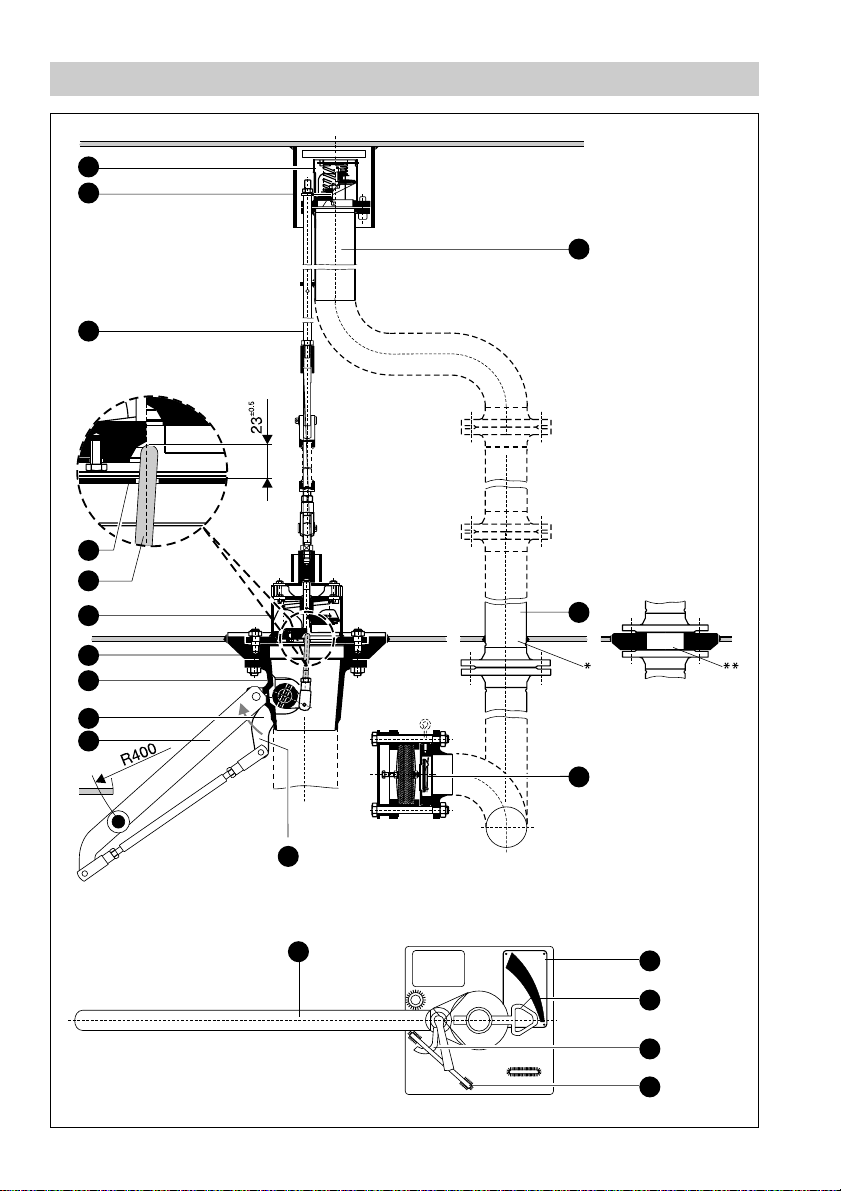
Functional elements
G
F
E
4
B
3
B
D
C
B
1
B
A
H
I
* welded directly into
tank shell
** boiler port with
valve-mounting flange
J
Fig. 2
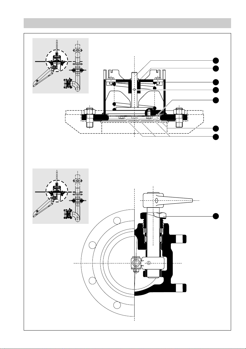
Fig. 3
4
Lever at limit stop
1
B
K
R
L
M
N
1
N
Page 5

Installation
G
F
X
W
V
U
T
S
R
Q
P
O
Fig. 4
Not part of the
GESTRA consignment
5
Page 6

Installation
2
A
Pipe 42.4 x 5.6 to DIN 2448,
carbon steel
L
L
L1
L
4
A
A
Pipe 42.4 x 5.6 to DIN 2448,
carbon steel
7
A1A5L
R1
R
L
B
1
B
Fig. 5
6
M
N1N K
6
A
1
A
2
A
Page 7
Maintenance
Fig. 6
1
D
1
R
O
Y
Z
3
D
2
D
Fig. 7
2
B
7
Page 8
Maintenance
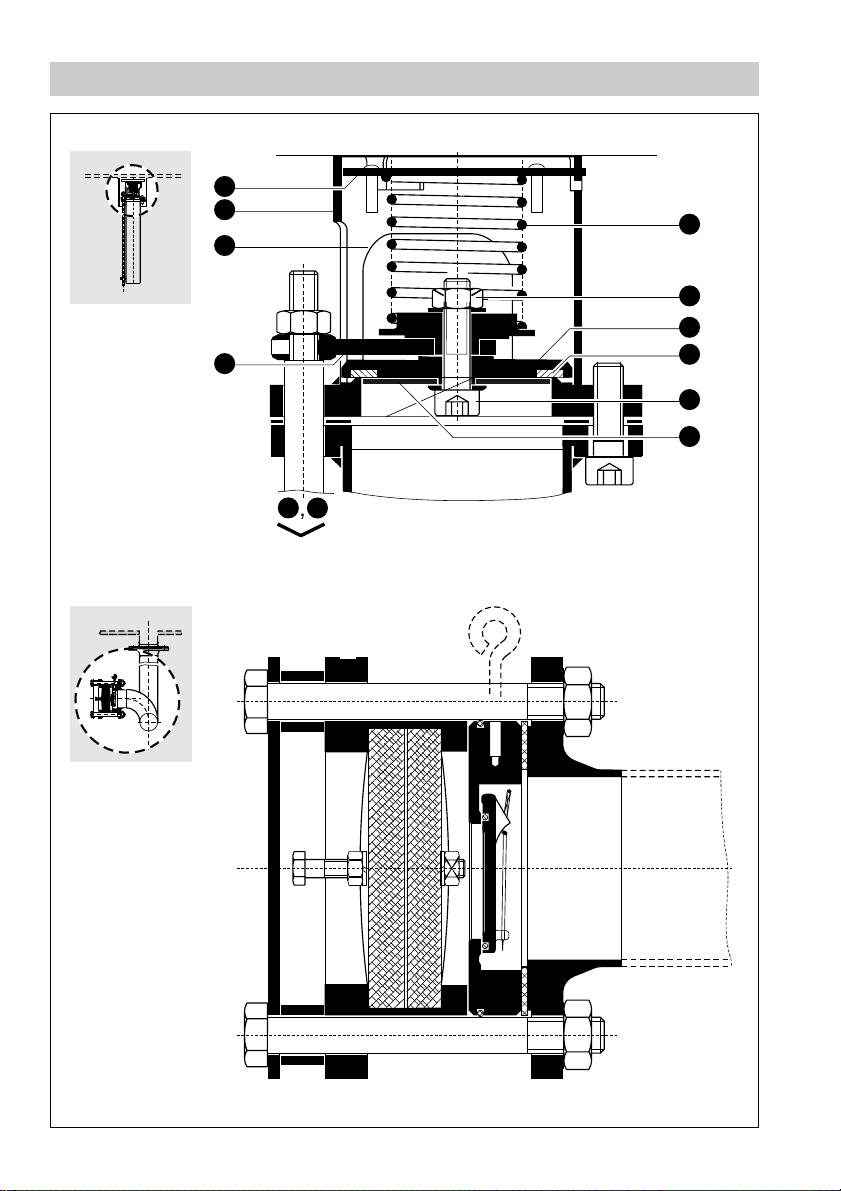
Fig. 8
3
G
4
G
5
G
G
6
G
10
G
9
2
G
T
U
G
7
G
8
G
Fig. 9
8
Page 9

Key
A
Manual operating mechanism EV 30
B
Operating mechanism BV 50, DN 150 mm
C
Valve mounting flange, DN 125/150 mm
D
Bottom valve UV 70, DN 125 mm
E
Actuating rod assembly with threaded bush for adjustment
F
Support for gas balance pipe (not included in the GESTRA consignment)
G
Vent valve LV 50, DN 80 mm
H
Connecting pipe LV 50 with rod assembly guide
I
Standpipe for gas balance pipe (not included in the GESTRA consignment),
– optional valve mounting flange not represented –
Vacuum breaker FV 10
J
K
Hand lever EV 30
Base plate EV 30
L
Indicator EV 30
M
Locking lever with hook for positions
N
1
Guide for hand lever
N
OPEN and CLOSED
All other items will be explained in the following pages and are therefore not listed here.
9
Page 10

Contents
Page
Important Notes
Safety note .................................................................................................................... 11
Danger ..........................................................................................................................11
Explanatory Notes
System description .......................................................................................................12
Function ........................................................................................................................12
Design ...........................................................................................................................12
General technical data ..................................................................................................13
Technical data of bottom valve UV 70 ..........................................................................13
Technical data of vent valve LV 50 DN 80 mm.............................................................1 3
Technical data of swing check valve fitted in FV 10.................................................... 1 3
Technical data of hand lever ....................................................................................... 1 3
Installation
Tools.............................................................................................................................. 15
Installation materials ..................................................................................................... 15
Bottom valve with operating mechanism ......................................................................1 5
Vent valve and standpipe (internal gas balance pipe)..................................................17
Maintenance
Tools.............................................................................................................................. 19
Bottom valve: Exchanging gasket .................................................................................19
Operating mechanism: Re-tightening stuffing box .......................................................20
Vent valve: Exchanging gasket.....................................................................................20
Operation
Open loading and unloading system EV 30 .................................................................22
Close loading and unloading system EV 30.................................................................22
10
Page 11

Important Notes
Safety Note
Use bottom loading system EV 30 only for loading and unloading tanks designed
for transporting products which are liquid at normal outside temperatures
(cf. temperature ratings on page 13). The system may only be installed by
qualified staff.
Qualified staff are those persons who have achieved a recognised level of
competence appropriate to the installation and commissioning of this equipment.
Danger
Do not undertake any installation or maintenance work unless the mobile
tank is completely empty and free of gas. Escaping vapours or gases
can endanger the life and health of the person entrusted with the
installation or maintenance and cause damage to property.
11
Page 12

Explanatory Notes
Scope of Supply
EV 30 DN 125 mm type F for liquid phase consisting of:
1 Valve mounting flange DN 125/150 mm (on request)
1 Bottom valve UV 70 DN 125 mm
1 Operating mechanism BV 50 DN 150 mm
1 Manual operating mechanism for EV 30
EV 30 DN 80 mm type G for gas phase consisting of:
1 Valve mounting flange LV 50 DN 80 mm (on request)
1 Vent valve LV 50 DN 80 mm with operating rod
1 Vacuum breaker FV 10
EV 30 DN 125 mm type F and EV 30 DN 80 mm type G can also be used singly.
System Description
The bottom loading system EV 30 consists of EV 30 DN 125 mm type F for liquid
phase and EV 30 DN 80 mm type G for gas phase (gas balance pipe) and is used in
mobile tanks, e.g. rail tank cars.
The system meets the requirements of the following rules:
■
GGVE/RID Appendix XI
■
TRT 024, TRT 006, TRT 30
Function
The bottom valve UV 70 DN 125 mm serves as first internal shut-off according to
GGVE/RID. The opening mechanism for the bottom valve UV 70 is incorporated in
the operating mechanism BV 50 on to which the corresponding manifold for loading/
unloading tank cars can be welded.
The valves for liquid and gas phases can be operated independently of each other
with the aid of hand levers. When the valve is in the open position the hand lever is
automatically locked. Visual position indication is provided by indicators on both sides
of the tank car.
The vent valve and the bottom valve are interlinked by means of a connecting rod,
which means that the vent valve is opened when the bottom valve is being opened.
The connecting rod also prevents the vent valve from opening when the fluid is
sloshing about in the tank.
The vacuum breaker FV 10 fitted in the gas balance pipe of the tank car opens if
negative pressure builds up when the gas balance pipe is not connected to the
tank car.
12
Page 13

Design
EV 30 DN 125 mm type F
■
Bottom valve UV 70 for DN 125 and 150 mm
■
Valve mounting flange EV 30 for DN 150 mm
■
Operating mechanism BV 50 DN 125/150 mm
EV 30 DN 80 mm type G
■
Vent valve LV 50 DN 80 mm
■
Flanged pipe socket for mounting LV 50
■
Vacuum breaker fitted with swing check valve and flame arrestor
Materials
■
Carbon steel or austenitic steel for corrosive fluids
General Technical Data
Type approval no.
EV 30 type F TÜ.AGG.276.97
LV 50 TÜ.AGG.277.97
Temperature/pressure ratings
Max. service pressure: 3 barg (43.5 psig)
Max. service temperature: + 150 °C (302 °F)
Min. service temperature: –10 °C (14°F) as defined by the German Technical
Directives for Tanks TRT 024
Technical Data of Bottom Valve UV 70
Spring forces
Position OPEN 1150 N
Position
CLOSED 700 N
Valve lift
Completely open: 37 mm, limited by stop
Safety distance between tappet and valve
2 mm
Technical Data of Vent Valve LV 50 DN 80 mm
Closing force: 140 N
Technical Data of Swing Check Valve Fitted in FV 10
Opens at a negative pressure of 0.07 barg (2.17 psig)
Technical Data of Hand Lever
Manual force required for opening
Without pressure: 56 N
At test pressure 4.5 barg (65 psig): 180 N
13
Page 14

Materials
EV 30 DN 125 mm type F
Standard design Austenitic design
Valve mounting flange 1.0425 H II 1.4571 X6CrNiMoTi 17 12 2
UV 70, DN 125 mm
Valve disc 1.0460 C22.8 1.4571 X6CrNiMoTi 17122
Seat ring 1.4301 X5CrNi 1810 1.4301 X5CrNi 1810
Bayonet socket pipe 1.0038 RSt 37-2 1.4541 X6CrNiTi 1810
Bayonet base cap 1.0308 St 35 1.4301 X5CrNi 1810
Spring 1.1200 Carbon spring 1.4310 X12CrNi 177
BV 50, DN 150 mm
Body 1.0619 GS-C 25 1.4308 G-X6CrNi 1 89
Shaft 1.4021 X20Cr 13 1.4301 X50CrNi 1 815
Screwed union 1.4301 X5CrNi 1810 1.4301 X5CrNi 1810
Other parts 1.0305 + St 35.8 + 1.4571 + X6CrNiMoTi 17122
0.7040 GGG-40 1.4308 A2 G-X6CrNi 1 89
Manual operating mechanism
Base plate 1.0038 RSt 37-2 Valves made of austenitic
Hand lever 0.7040 GGG-40 materials have the operating
Operating shaft 1.4104 X12CrMoS 17 mechanisms also made of
Lever 0.7040 GGG-40 carbon steel (= standard
Supporting arm 1.0110 St 37 design)
steel wire
EV 30 DN 80 mm type G
Standard design Austenitic design
Valve mounting flange 1.0425 H II 1.4571 X6CrNiMoTi 17 12 2
LV 50, DN 80 mm
Internals 1.4301 X5CrNi 1810 1.4301 X5CrNi 1810
Flanges 1.4301 X5CrNi 1 81 0 1.4571 X6CrNiMoTi 1 7122
Bayonet socket pipe 1.0038 RSt 37-2 1.4541 X6CrNiTi 18 10
Bayonet base cap 1.0308 St 35 1.4301 X5CrNi 1810
Spring 1.4310 X12CrNi 1 77 1.4310 X12CrNi 1 77
Connecting pipe L V 50
Flange 1.0038 RSt 37 -2 1.4301 X5CrNi 18 10
Pipe 1.0305 St 35.8 1.4301 X5CrNi 18 10
Bayonet base cap UV 70 (welded part)
Bayonet base cap 1.0308 St 35 1.4301 X5CrNi 1810
Pipe 1.0305 St 35.8 1.4571 X6CrNiTi 18 10
T appet 1.4301 X5CrNi 1810 1.4301 X5CrNi 1810
Parts for assembly LV 50
Socket-head cap screw A2 A2
Operating rod 1.0711.07 9 S 20 1.4301 X5CrNi 18 10
FV 10, DN 80 mm
Adaptor 1.0254... ST 37.0 – –
CB 26
Body 1.0460... C 22.8 – –
Flap 1.4581... G-X7CrNiMoNb 1810 – –
O-ring FKM – – –
Bow spring 1.4571K X10CrNiMoTi 1 81 0 – –
Backfire grid assembly
Body Ms 64 – – –
Backfire grid 1.4541... X10CrNiTi 189
14
Page 15

Installation
Dimensions and component parts see Fig. 1 – 4
Tools
For installation and maintenance work use tools commonly used by fitters and
mechanics.
Installation Materials
The following items are to be provided on site:
■
Standpipe for gas balance pipe
■
Support for gas balance pipe
■
Guide for gas phase valve
■
Connecting rod between gas and liquid phase valve
■
Valve mounting flange (unless supplied by GESTRA)
Bottom Valve with Operating Mechanism
see Fig. 2, 3 and 5
1. Weld valve mounting flange on to tank bottom.
2. Weld manifold to operating mechanism .
3. Screw fixing studs for operating mechanism from below into the valve mounting
C
flange . Put gasket onto the sealing face of the operating mechanism. Attach
gasket and operating mechanism to valve mounting flange by fastening the nuts of
the fixing studs, torque required for tightening 90 Nm.
4. Place tappet guide onto valve mounting flange and pass tappet through
B
guide.
5. Check correct position of tappet (specified setting 23 ± 0.5 mm) from inside of
tank. When checking, make sure that the lever of the operating mechanism is
at the limit stop.
Limit stop: With the tappet guide inser ted it should not be possible to turn the
lever any further in direction of arrow.
If required re-adjust position of tappet by pushing in or pulling out the tappet
until the specified setting is attained.
C
B
B
4
3
B
C B
3
B
Attention
After adjusting the tappet fix it firmly to the clevis by fastening the nut on
the tappet (see Fig. 3)
6. Screw fixing studs for the bottom valve inside the tank into the valve mounting
C
flange . Put gasket and guide onto the seating for the bottom valve and then fit
bottom valve . When putting bottom valve in place make sure that the tappet
D
D
extends into the central recess in the valve disc. Tighten nuts in steps to a torque
of 90 Nm.
15
Page 16

Bottom Valve with Operating Mechanism – continued –
See Fig. 5
6
7. Attach suppor t to operating mechanism by using a pin.
8. Position base plates and with shaft and as specified on page 6
(for dimensions refer to Fig. 5 B) to the tank car.
Size connecting sleeves and (not included in GESTRA consignment)
A
L
L
R
L
4
A
5
A
according to the formulae for length X =
ends with holes as specified in Fig. 5 (∅ 10
1
9. Put lever onto shaft . The linear size of the connecting rod should be
420 – 450 mm (cf. Fig. 5 B) for basic adjustment. Attach connecting rod to
levers and . Put connecting sleeves and between base plates
and and shaft .
A
1
A
R
L
1
B
7
A
7
A
B
L1
L
L
– 168 and Y =
2
H11
mm).
4
A
R1
L
L
– 230 and provide their
2
2
A
5
A
2
A
Attention
1
Make sure that lever is at the limit stop.
B
L
L
7
Mark position of hole on shaft for pin of lever . Withdraw connecting sleeves
4
A
and . Remove shaft from support and connecting rod from
lever . Drill a hole ∅ 10
5
A
1
A
A
7
A
H11
mm at the marking in the shaft using a
1
A
6
A
7
A
2
A
pillar drilling machine.
7
10.Mount shaft in support . Put lever onto shaft and secure with a pin.
Place connecting sleeves and between shafts and . Attach
connecting rod to levers and . If the connecting rod does not fit
A
2
A
properly turn the setting screws to adjust the correct linear size.
6
A
4
A
A
1
A
3
A
1
A
5
1
B
7
A
L1
L
R1
L
2
A
Attention
2
After the adjustment re-tighten firmly all nuts of the connecting rod .
Note that one of the two threaded rods fitted in the connecting rod
A
2
A
features a left-hand thread.
11.The two indicators must point to the position CLOSED (see Fig. 5 A). Attach
connecting sleeves and to shafts and using a pin and a split pin.
Drill a hole ∅ 10
5
A
and by means of a pin and split pin.
12.Turn the locking hook clockwise. Pull the hand lever towards the indicator
and connect the hand lever with the indicator. Press down the hand lever to
open the bottom valve. When the valve is open the locking hook engages
into the locking guide , keeping the bottom valve in the open position.
When the valve is open the lift of the valve disc must be 37
N
hook does not engage at the rear of the locking guide grind off the bottom
M
4
A
H11
mm in shaft . Attach shaft to connecting sleeves
N K M
N
5
A
7
A
1
L1
L
R1
L
Y
N
-2
mm. If the locking
1
N
4
A
K
edge of the locking guide until the locking hook engages.
16
Page 17

Vent valve and standpipe (internal gas balance pipe)
see Fig. 4
1. Weld support from inside into the tank top, taking spacing specifications
F
(59 ± 2) into account. The support is not par t of the GESTRA consignment. We
recommend using a pipe (168.3x4.5 mm) as suppor t.
Attention
The grooves (145x18 mm – cf. Fig. 4) of the support have to be crosswise
to the longitudinal axis of the tank.
2. Weld valve mounting flange or socket for standpipe according to Fig. 4 a and
I
4b into the tank bottom.
3. Weld pipe end with flange for mounting the vent valve to the internal standpipe.
Attention
X
Guide has to be in alignment with the centre line of the bottom valve.
4. Mount vent valve with operating rod onto the flange before fitting the
G W
standpipe in the tank. To do that, put the gasket onto the seating surface of the
flange and then tighten the four cheese-head screws to fix the vent valve firmly in
place. Tightening torque 50 Nm
5. Attach the standpipe with the vent valve to support . Put a gasket onto the valve
F
mounting flange or tank socket and secure the standpipe with the vent valve by
using bolts.
6. Screw operating rod to vent valve using washers and nuts (see Fig. 4).
Screw lock nut onto operating rod up to the end of thread.
Screw connecting sleeve onto operating rod , taking specified setting
GW
WV
WU
(30 ± 1 mm) into account.
7. Put bayonet base cap onto bayonet socket pipe and insert square connecting
piece into bayonet base cap .
RS
OR
8. The length of the connecting rod (not part of the GESTRA consignment) is found
by adding the linear size Z (distance between connecting sleeve and square
connecting piece ) to the depth of insertion (2x15 mm). From this it follows that
S
U
the length of the connecting rod = linear size Z + 30 mm.
(Rule of thumb for determining the size of the connecting rod: Inside diameter of
tank minus 650 mm; the exact sizing should be effected when fitting the
connecting rod.)
9. Remove connecting sleeve and square piece .
SU
Cut the connecting rod (∅ 22 mm, made of carbon steel or, in case of austenitic
design, of DIN material 1.4305 or equivalent) to the respective length and weld it
to the connecting sleeve and square piece .
Connecting sleeve and square piece (at weld area) are made of:
SU
SU
Standard design: Forged steel C22.8 (DIN no. 1.0460)
Austenitic design: S. S. type X6CrNiTi 1810 (DIN no. 1.4541)
17
Page 18

Vent valve and standpipe (internal gas balance pipe) – continued –
10.Use operating rod to open the vent valve . Fix it in place by inserting a
suitable fixing pin (∅ 4 mm) into the hole above the guide .
Pass connecting rod into the guide pipe of the bayonet base cap and
screw it into the connecting sleeve by turning it to the r ight until the
T R
U
adjustment setting 30±1 mm is attained. Tighten lock nut , remove fixing
pin and close the vent valve .
G
GW
X
V
Checking the adjustment
The square piece has to protrude 15 +2 mm from the guide pipe.
S
It must be easily possible to push the complete operating rod assembly
(connecting rod and operating rod weigh approx. 8 kg) smoothly approx.
6 mm upwards (vent valve does not open yet, i.e. idle lift).
If this is not possible modify the adjustment setting in such a way that the
specified setting (15
(6±0.5 mm) is also taken into account. Secure the bayonet base cap by
using hexagon-head bolts M8x40 and nuts M8 .
T W
G
+2
mm) is maintained and the idle lift of the valve
PQ
R
18
Page 19

Maintenance
Attention
Before carrying out any maintenance work inside the tank make sure that
the latter is accessible and sufficiently aearated.
After servicing check the adjustments as specified in the section
“Installation”.
We recommend to replace the gaskets of the bottom valve and the vent valve after
every tank inspection.
Tools
For installation and maintenance work use tools commonly used by fitters and
mechanics.
Bottom Valve: Replacing Gasket
See Fig. 2, 4, 6
1. Loosen connecting rod (linked with and ) from bottom valve.
2. Unscrew fixing bolts of bayonet base cap . Pull bayonet base cap out of the
bayonet socket pipe .
3. Use manual operating mechanism to open the bottom valve.
1
4. Fix valve disc by inserting a pin ∅ 5 mm into the hole .
D
5. Use manual operating mechanism to close the bottom valve. The valve disc is
kept in the open position by virtue of the fixing pin.
6. Remove valve disc with guide and spring from bayonet socket pipe.
7. Check adjustment setting 23±0.5 mm at tappet of the operating mechanism
(see Fig. 2) and, if necessary, adjust the tappet as described in the section
“Installation”.
8. Undo the three hexagon-head screws fastening the mounting base to the
valve disc . Remove the mounting base and gasket .
1
D
9. Put new gasket into the valve disc, place mounting base onto the valve disc
and fasten the three hexagon-head screws; torque required for tightening:
18 Nm.
10.Put valve disc with guide and spring into the bayonet socket pipe and guide
into the bayonet base cap.
11.Push hand lever in the opening position.
T S U
O
1
D
1
R
R
Y
3
B
2
D
3
D
Z
3
D
3
D
R
Attention
3
Make sure that the tappet extends into the recess in the valve disc.
B
19
Page 20

Bottom Valve: Replacing Gasket – continued –
12.Remove fixing pin from the hole and close the bottom valve.
13.Put bayonet base cap into bayonet socket pipe and secure with bolts.
R O
Y
14.Attach connecting rod to bottom valve.
Required spare parts:
Designation Material Ref. no.
Gasket FPM 049230
Gasket PTFE 048571
Please state the reference number when ordering these parts at GESTRA.
Operating Mechanism: Retightening Stuffing Box
See Fig. 7
Normally it is not necessary to re-tighten the stuffing box between tank car
inspections.The stuffing box is, to a certain degree, self-tightening.
Inserting additional packing ring:
2
1. Undo screwed union , six-point socket of spanner: 55 A. F
B
2. Take disk springs and pressure pad off the stuffing box.
3. Insert additional packing ring.
4. Put gland and disk springs onto the stuffing box.
2
5. Fasten screwed union to stuffing box and preload disk springs.
B
Required spare parts:
Designation Material Ref. no.
Packing PTFE 048648
Please state the reference number when ordering these parts at GESTRA.
Vent Valve: Exchanging Gasket
See Fig. 4, 8
1. Loosen connecting rod (linked with and ) from the bottom valve.
T S U
2. Detach internal gas balance pipe from valve mounting flange or pipe socket.
3. Undo the four fixing screws of the vent valve.
2
4. Detach the connecting rod from the driving pin of the vent valve.
3
5. Remove bayonet base cap by pulling it down and turning it anticlockwise out
of the bayonet socket pipe .
G
4
G
G
20
Page 21

Vent Valve: Exchanging Gasket – continued –
Attention
3
Note that the bayonet base cap is spring loaded.
– Spring force when spring is mounted: 140 N
– Length of unloaded spring : 157 mm
6
6. Unscrew nut , using a hexagon socket spanner for holding the cheese head
G
bolt .
7. Remove retaining plate and gasket from valve disc .
8. Insert new gasket in valve disc . Attach retaining plate and spring disk
G
7
8
G
G
to valve disc using cheese head bolts and nuts. Torque required for
G
5
G
9
G
10
7
G
10
G
8
G
tightening: 30 Nm.
5
9. Put spring onto spring disk and press bayonet base cap against the spring
until the pins engage in the corresponding J-shaped slots of the bayonet socket
pipe . Then rotate the bayonet base cap clockwise until its pins are seated
G
4
G
3
G
firmly in the slots.
2
10.Attach operating rod and driving pin to the vent valve.
G
11.Put a new gasket on the vent valve and fix it to the gas balance pipe with four
socket-head cap screws, torque required for tightening: 50 Nm.
12.Mount gas balance pipe with vent valve to the valve mounting flange or pipe
socket of the tank.
13.Attach connecting rod to bottom valve.
Required spare parts:
Designation Material Ref. no.
Gasket FPM 008372
Gasket PTFE 008860
Gasket Centellen 048597
Please state the reference number when ordering these parts at GESTRA.
21
Page 22

Operation
Opening the loading and unloading system EV 30
See Fig. 1, 3, 5
1. Turn locking hook clockwise upwards to unlock the hand lever .
2. After unlocking the hand lever pull the latter with both hands towards the
indicator until they are firmly interlocked.
M
3. Release the locking hook and open the bottom valve with the interlocking vent
valve by pulling down the hand lever. In this position the locking hook will
automatically engage at the rear of the locking guide , thereby keeping the
valves open.
4. The indicator visually indicates on both sides of the tank car that the valves
are open.
Closing the loading and unloading system EV 30
See Fig. 1, 3, 5
Attention
N K
K
N
N
M
1
N
Note that hand lever is spring-loaded. In case of improper handling the
K
lever may spring upwards.
1. Push hand lever in the opening position. Turn the locking hook clockwise
upwards until the hook disengages from the locking guide .
2. Move the hand lever slowly upwards to close the valve system.
3. Push back hand lever with both hands (disengaging indicator ) until the
locking hook engages.
4. The indicator visually indicates on both sides of the tank car that the valves
K N
K
K M
N
M
1
N
are closed.
22
Page 23

23
Page 24

GESTRA Gesellschaften · GESTRA Companies · Sociétés GESTRA · Sociedades Gestra · Società GESTRA
GESTRA Gesellschaften · GESTRA Companies · Sociétés GESTRA · Sociedades Gestra · Società GESTRA
Vertretungen weltweit · Agencies all over the world · Représentations dans le monde entier · Representaciones en todo el mundo · Agenzie in tutto il mondo
Vertretungen weltweit · Agencies all over the world · Représentations dans le monde entier · Representaciones en todo el mundo · Agenzie in tutto il mondo
España
España
GESTRA ESPAÑOLA S.A.
GESTRA ESPAÑOLA S.A.
Luis Cabrera, 86-88
Luis Cabrera, 86-88
E-28002 Madrid
E-28002 Madrid
Tel. 003491/5 152032
Tel. (091) 5 152032
Fax0 03491/413 6747; 515 2036
Fax (091) 4 136 747; (091) 5152036
E-mail: gestra@gestra.es
France
France Portugal
GESTRA S.A.R.L.
10 Avenue du Centaure, BP 8263
Flowserve Flow Control S.A.S.
F-95801 CERGY PONTOISE
10 Avenue du Centaure, BP 8263
Tél. (01) 34.43.26.60
F-95801 CERGY PONTOISE CEDEX
Fax (01) 34.43.26.87
Tél. 0 0331/34432660
Fax 00331/34432687
Italia
E-mail: gnation@flowserve.com
Polska
Polska
GESTRA POLONIA Spolka zo.o.
GESTRA POLONIA Spolka z o. o.
Ul. Schuberta 104, P.O. Box 71
Ul. Schuberta 104
PL-80-172 Gdansk
PL-80-172 Gdansk
Tel. 004858/ 30610 02 oder 30610 10
Tel. (058) 306 10 02
Fax 00 4858 /3061003 oder 3063300
Fax (058) 306 10 03
E-mail: gestra@gestra.pl
Portugal
GESTRA PORTUGUESA VALVULAS LDA.
Av. Dr. Antunes Guimarães, 1159
GESTRA PORTUGUESA VALVULAS LDA.
P-4100 Porto
Av. Dr. Antunes Guimarães, 1159
Tel. (02) 6 10 75 51
Porto 4100-082
Fax (02) 6 10 75 75
Tel. 0035122/ 619 87 70
Fax 0035122/6107575
E-mail: gestra@gestra.pt
ITALGESTRA S.r.l.
Via Carducci 125
Italia
l-20099 S.S. Giovanni (MI)
Tel. (02) 2 62 97-0
Italgestra S.r.l.
Fax (02) 26 2974 60
Via Carducci 125
l-20099 Sesto San Giovanni (MI)
Tel. 003902/ 241012.1
Fax 00 3902 /241012.460
E-mail: info@italgestra.it
®
®
GESTRA GmbH
GESTRA GmbH
Postfach 10 5 460
Postfach 10 54 60
D-28054 Bremen
D-28054 Bremen
Hemmstraße 130
Münchener Str. 77
D-28215 Bremen
D-28215 Bremen
Tel. + 49 (0) 421 35 03- 0
Tel. +49 (0) 421 3503-0
Fax +49 (0) 421 35 03-393
Fax+49 (0) 421 35 03-393
Internet www.gestra.de
E-mail
gestra.gmbh@gestra.de
E-mail
gestra.gmbh@gestra.de
Internet www.gestra.de
A Unit of Flowserve Corporation
An Invensys company
810496-00/1299c · ©1997 GESTRA GmbH · Bremen · Printed in Germany
24
 Loading...