

Page 1
USER INSTRUCTIONS
ESP3 Vertical Immersion Sump Pump
Mark 3 Standard, Lo-Flo and Recessed Impeller Hydraulics
PCN=26999943 – 08-11 (E)
Original Instructions
Installation
Operation
Maintenance
Page 2

ESP3 USER INSTRUCTIONS ENGLISH 26999943 08-11
of 64
CONTENTS
Page
1 INTRODUCTION AND SAFETY ...........................3
1.1 General ...........................................................3
1.2 CE marking and approvals..............................3
1.3 Disclaimer .......................................................3
1.4 Copyright.........................................................3
1.5 Duty conditions................................................3
1.6 Safety..............................................................4
1.7 Name plate and safety labels..........................7
1.8 Specific machine performance........................7
1.9 Noise level.......................................................7
2 TRANSPORT AND STORAGE.............................9
2.1 Consignment receipt and unpacking...............9
2.2 Handling..........................................................9
2.3 Lifting...............................................................9
2.4 Storage............................................................9
2.5 Recycling and end of product life..................10
3 DESCRIPTION ....................................................10
3.1 Configurations...............................................10
3.2 Nomenclature................................................10
3.3 Design of major parts.................................... 11
3.4 Performance and operation limits.................. 11
4 INSTALLATION ................................................... 17
4.1 Location.........................................................18
4.2 Part assemblies.............................................18
4.3 Foundation .................................................... 18
4.4 Pump Mounting.............................................18
4.5 Mechanical seals and packing......................18
4.6 Driver Mounting.............................................19
4.7 Piping ............................................................ 19
4.8 Final free rotation check................................23
4.9 Auxiliary piping..............................................23
4.10 Electrical connections .................................23
4.11 Level controls ..............................................23
4.12 Protection systems......................................31
6 MAINTENANCE ...................................................37
6.1 Maintenance schedule...................................37
6.2 Spare parts.....................................................38
6.3 Recommended spares and consumable items
7 FAULTS; CAUSES AND REMEDIES..................51
8 PARTS LIST AND DRAWINGS...........................53
9 CERTIFICATION..................................................62
10 OTHER RELEVANT DOCUMENTATION AND
.......................................................................38
6.4 Tools required................................................38
6.5 Fastener torques............................................39
6.6 Setting impeller clearance and impeller
replacement ...................................................40
6.7 Disassembly ..................................................41
6.8 Examination of parts......................................43
6.9 Assembly of pump and seal...........................46
8.1 General arrangement drawing.......................62
MANUALS...........................................................62
10.1 Supplementary User Instructions ................62
10.2 Change notes ..............................................62
10.3 Additional sources of information ................62
Page
5 COMMISSIONING, STARTUP, OPERATION AND
SHUTDOWN ......................................................31
5.1 Pre-commissioning procedure......................31
5.2 Bearing Lubrication ....................................... 31
5.3 Impeller clearance.........................................34
5.4 Direction of rotation.......................................34
5.5 Guarding .......................................................34
5.6 Priming and auxiliary supplies ......................34
5.7 Starting the pump..........................................34
5.8 Running or operation ....................................35
5.9 Stopping and shutdown.................................36
5.10 Hydraulic, mechanical and electrical duty...36
Page 2
Page 3
ESP3 USER INSTRUCTIONS ENGLISH 26999943 08-11
of 64
1 INTRODUCTION AND SAFETY
1.1 General
These instructions must always be kept
close to the product's operating location or
directly with the product.
Flowserve products are designed, developed and
manufactured with state-of-the-art technologies in
modern facilities. The unit is produced with great
care and commitment to continuous quality control,
utilizing sophisticated quality techniques, and safety
requirements.
Flowserve is committed to continuous quality
improvement and being at your service for any further
information about the product in its installation and
operation or about its support products, repair and
diagnostic services.
These instructions are intended to facilitate
familiarization with the product and its permitted use.
Operating the product in compliance with these
instructions is important to help ensure reliability in
service and avoid risks. The instructions may not
take into account local regulations; ensure such
regulations are observed by all, including those
installing the product. Always coordinate repair
activity with operations personnel, and follow all plant
safety requirements and applicable safety and health
laws/regulations.
These instructions must be read prior to
installing, operating, using and maintaining the
equipment in any region worldwide. The
equipment must not be put into service until all
the conditions relating to safety noted in the
instructions, have been met. Failure to follow and
apply the present user instructions is considered
to be misuse. Personal injury, damage, delay or
failure caused by misuse is not covered by the
Flowserve warranty.
1.2 CE marking and approvals
It is a legal requirement that machinery and equipment
put into service within certain regions of the world shall
conform with the applicable CE Marking Directives
covering Machinery and, where applicable, Low Voltage
Equipment, Electromagnetic Compatibility (EMC),
Pressure Equipment Directive (PED) and Equipment for
Potentially Explosive Atmospheres (ATEX).
Where applicable, the Directives and any additional
Approvals, cover important safety aspects relating to
machinery and equipment and the satisfactory provision
of technical documents and safety instructions. Where
applicable this document incorporates information
relevant to these Directives and Approvals.
To confirm the Approvals applying and if the product is
CE marked, check the serial number plate markings
and the Certification. (See section 9, Certification.)
1.3 Disclaimer
Information in these User Instructions is believed
to be complete and reliable. However, in spite of
all of the efforts of Flowserve Corporation to
provide comprehensive instructions, good
engineering and safety practice should always be
used.
Flowserve manufactures products to exacting
International Quality Management System Standards
as certified and audited by external Quality
Assurance organizations. Genuine parts and
accessories have been designed, tested and
incorporated into the products to help ensure their
continued product quality and performance in use.
As Flowserve cannot test parts and accessories
sourced from other vendors the incorrect
incorporation of such parts and accessories may
adversely affect the performance and safety features
of the products. The failure to properly select, install
or use authorized Flowserve parts and accessories is
considered to be misuse. Damage or failure caused
by misuse is not covered by the Flowserve warranty.
In addition, any modification of Flowserve products or
removal of original components may impair the safety
of these products in their use.
1.4 Copyright
All rights reserved. No part of these instructions may
be reproduced, stored in a retrieval system or
transmitted in any form or by any means without prior
permission of Flowserve.
1.5 Duty conditions
This product has been selected to meet the
specifications of your purchaser order. The
acknowledgement of these conditions has been sent
separately to the Purchaser. A copy should be kept
with these instructions.
The product must not be operated beyond
the parameters specified for the application. If
there is any doubt as to the suitability of the
product for the application intended, contact
Flowserve for advice, quoting the serial number.
If the conditions of service on your purchase order are
going to be changed (for example liquid pumped,
Page 3
Page 4
ESP3 USER INSTRUCTIONS ENGLISH 26999943 08-11
of 64
temperature or duty) it is requested that the user seeks
the written agreement of Flowserve before start up.
1.6 Safety
1.6.1 Summary of safety markings
These User Instructions contain specific safety
markings where non-observance of an instruction would
cause hazards. The specific safety markings are:
This symbol indicates electrical safety
instructions where non-compliance will involve a high
risk to personal safety or the loss of life.
This symbol indicates safety instructions where
non-compliance would affect personal safety and
could result in loss of life.
This symbol indicates “hazardous and toxic fluid”
safety instructions where non-compliance would affect
personal safety and could result in loss of life.
This symbol indicates safety
instructions where non-compliance will involve some
risk to safe operation and personal safety and would
damage the equipment or property.
This symbol indicates explosive atmosphere
zone marking according to ATEX. It is used in safety
instructions where non-compliance in the hazardous
area would cause the risk of an explosion.
1.6.3 Safety action
This is a summary of conditions and actions to
help prevent injury to personnel and damage to
the environment and to equipment. For products
used in potentially explosive atmospheres
section 1.6.4 also applies.
NEVER DO MAINTENANCE WORK
WHEN THE UNIT IS CONNECTED TO POWER
(Lock out.)
DRAIN THE PUMP AND ISOLATE PIPEWORK
BEFORE DISMANTLING THE PUMP
The appropriate safety precautions should be taken
where the pumped liquids are hazardous.
FLUOROELASTOMERS (When fitted.)
When a pump has experienced temperatures over
250 ºC (482 ºF), partial decomposition of
fluoroelastomers (example: Viton) will occur. In this
condition these are extremely dangerous and skin
contact must be avoided.
HANDLING COMPONENTS
Many precision parts have sharp corners and the
wearing of appropriate safety gloves and equipment
is required when handling these components. To lift
heavy pieces above 25 kg (55 lb) use a crane
appropriate for the mass and in accordance with
current local regulations.
This symbol is used in safety instructions to
remind not to rub non-metallic surfaces with a dry
cloth; ensure the cloth is damp. It is used in safety
instructions where non-compliance in the hazardous
area would cause the risk of an explosion.
This sign is not a safety symbol but indicates
an important instruction in the assembly process.
1.6.2 Personnel qualification and training
All personnel involved in the operation, installation,
inspection and maintenance of the unit must be
qualified to carry out the work involved. If the
personnel in question do not already possess the
necessary knowledge and skill, appropriate training
and instruction must be provided. If required the
operator may commission the manufacturer/supplier
to provide applicable training.
Always coordinate repair activity with operations and
health and safety personnel, and follow all plant
safety requirements and applicable safety and health
laws and regulations.
NEVER OPERATE THE PUMP WITHOUT THE
COUPLING GUARD AND ALL OTHER SAFETY
DEVICES CORRECTLY INSTALLED
GUARDS MUST NOT BE REMOVED WHILE
THE PUMP IS OPERATIONAL
THERMAL SHOCK
Rapid changes in the temperature of the liquid within
the pump can cause thermal shock, which can result
in damage or breakage of components and should be
avoided.
NEVER APPLY HEAT TO REMOVE IMPELLER
Trapped lubricant or vapor could cause an explosion.
HOT (and cold) PARTS
If hot or freezing components or auxiliary heating
equipment can present a danger to operators and
persons entering the immediate area, action must be
taken to avoid accidental contact (such as shielding). If
complete protection is not possible, the machine access
must be limited to maintenance staff only with clear
visual warnings and indicators to those entering the
Page 4
Page 5
ESP3 USER INSTRUCTIONS ENGLISH 26999943 08-11
of 64
immediate area. Note: bearing housings must not be
insulated and drive motors and bearings may be hot.
If the temperature is greater than 80 °C (176°F) or
below -5 °C (23 °F) in a restricted zone, or
exceeds local regulations, action as above shall
be taken.
HAZARDOUS LIQUIDS
When the pump is handling hazardous liquids care
must be taken to avoid exposure to the liquid by
appropriate pump placement, limiting personnel
access and by operator training. If the liquid is
flammable and/or explosive, strict safety procedures
must be applied.
Gland packing must not be used when pumping
hazardous liquids.
PREVENT EXCESSIVE EXTERNAL
PIPE LOAD
Do not use pump as a support for piping. Do not
mount expansion joints, unless allowed by Flowserve
in writing, so that their force, due to internal pressure,
acts on the pump flange.
ENSURE CORRECT LUBRICATION
(See section 5, Commissioning, startup, operation
and shutdown.)
NEVER EXCEED THE MAXIMUM
DESIGN PRESSURE (MDP) AT THE
TEMPERATURE SHOWN ON THE PUMP
NAMEPLATE
See section 3 for pressure versus temperature
ratings based on the material of construction.
NEVER OPERATE THE PUMP WITH
THE DISCHARGE VALVE CLOSED
(Unless otherwise instructed at a specific point in the
User Instructions)
(See section 5, Commissioning start-up, operation
and shutdown.)
NEVER RUN THE PUMP DRY OR
WITHOUT PROPER PRIME (Casing flooded)
NEVER OPERATE THE PUMP WITH
THE SUCTION VALVE CLOSED
It should be fully opened when the pump is running.
NEVER OPERATE THE PUMP AT
ZERO FLOW OR FOR EXTENDED PERIODS
BELOW THE MINIMUM CONTINUOUS FLOW
THE PUMP SHAFT MUST TURN
CLOCKWISE WHEN VIEWED FROM THE MOTOR
END
It is absolutely essential that the rotation of the motor
be checked before installation of the coupling drive
element and starting the pump. Incorrect rotation of
the pump for even a short period can unscrew the
impeller, which can cause significant damage.
1.6.4 Products used in potentially explosive
atmospheres
Measures are required to:
• Avoid excess temperature
• Prevent buildup of explosive mixtures
• Prevent the generation of sparks
• Prevent leakages
• Maintain the pump to avoid hazard
The following instructions for pumps and pump units
when installed in potentially explosive atmospheres
must be followed to help ensure explosion protection.
Both electrical and non-electrical equipment must meet
the requirements of European Directive 94/9/EC.
1.6.4.1 Scope of compliance
Use equipment only in the zone for which it is
appropriate. Always check that the driver, drive
coupling assembly, seal and pump equipment are
suitably rated and/or certified for the classification of
the specific atmosphere in which they are to be
installed.
Where Flowserve has supplied only the bare shaft
pump, the Ex rating applies only to the pump. The
party responsible for assembling the pump set shall
select the coupling, driver, seal and any additional
equipment, with the necessary CE Certificate/
Declaration of Conformity establishing it is suitable for
the area in which it is to be installed.
The output from a variable frequency drive (VFD) can
cause additional heating affects in the motor. On
pump installations controlled by a VFD, the ATEX
Certification for the motor must state that it covers the
situation where electrical supply is from the VFD.
This particular requirement still applies even if the
VFD is in a safe area.
Page 5
Page 6
ESP3 USER INSTRUCTIONS ENGLISH 26999943 08-11
of 64
Temperature
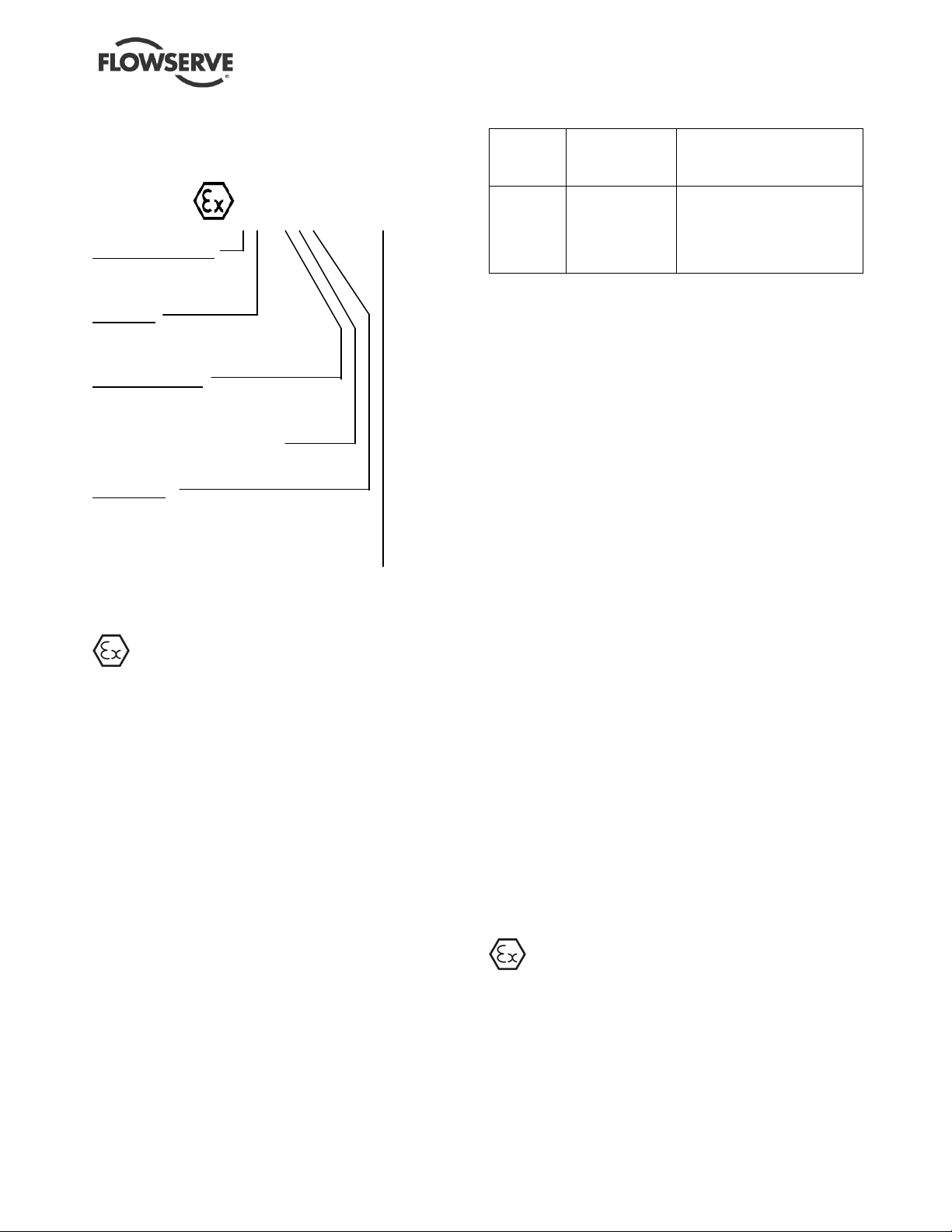
1.6.4.2 Marking
An example of ATEX equipment marking is shown
below. The actual classification of the pump will be
engraved on the nameplate.
II 2 GD c IIC 135ºC (T4)
Equipment Group
I = Mining
II = Non-mining
Category
2 or M2 = High level protection
3 = normal level of protection
Gas and/or dust
G = Gas
D = Dust
c = Constructional safety
(in accordance with En13463-5)
Gas Group
IIA – Propane (Typical)
IIB – Ethylene (Typical)
IIC – Hydrogen (Typical)
Maximum surface temperature (Temperature Class)
(see section 1.6.4.3)
1.6.4.3 Avoiding excessive surface temperatures
ENSURE THE EQUIPMENT TEMPERATURE
CLASS IS SUITABLE FOR THE HAZARD ZONE
Pump liquid temperature
Pumps have a temperature class as stated in the ATEX
Ex rating on the nameplate. These are based on a
maximum ambient temperature of 40 ºC (104 ºF); refer
to Flowserve for higher ambient temperatures.
The surface temperature on the pump is influenced by
the temperature of the liquid handled. The maximum
permissible liquid temperature depends on the
temperature class and must not exceed the values in the
table applicable below.
Maximum permitted liquid temperature for pumps
Maximum
class to
EN 13463-1
T6
T5
T4
T3
T2
T1
* The table only takes the ATEX temperature class into consideration.
Pump design or material, as well as component design or material,
may further limit the maximum working temperature of the liquid.
surface
temperature
permitted
85 °C (185 °F)
100 °C (212 °F)
135 °C (275 °F)
200 °C (392 °F)
300 °C (572 °F)
450 °C (842 °F)
Temperature limit of liquid
handled (* depending on
material and construction
variant – check which is lower)
Consult Flowserve
Consult Flowserve
115 °C (239 °F) *
180 °C (356 °F) *
275 °C (527 °F) *
400 °C (752 °F) *
The temperature rise at the seals and bearings and due
to the minimum permitted flow rate is taken into account
in the temperatures stated.
The responsibility for compliance with the specified
maximum liquid temperature is with the plant
operator.
Temperature classification “Tx” is used when the
liquid temperature varies and the pump could be
installed in different hazardous atmospheres. In this
case the user is responsible for ensuring that the
pump surface temperature does not exceed that
permitted in the particular hazardous atmosphere.
Do not attempt to check the direction of rotation with the
coupling element/pins fitted due to the risk of severe
contact between rotating and stationary components.
Where there is any risk of the pump being run against a
closed valve generating high liquid, casing and
discharge pipe external surface temperatures, fit an
external surface temperature protection device.
Avoid mechanical, hydraulic or electrical overload by
using motor overload trips, temperature monitor or a
power monitor and perform routine vibration monitoring.
In dirty or dusty environments, make regular checks
and remove dirt from areas around close clearances,
bearing housings and motors.
1.6.4.4 Preventing the buildup of explosive
mixtures
Page 6
ENSURE PUMP IS PROPERLY FILLED AND
VENTED AND DOES NOT RUN DRY
Ensure that the pump and relevant suction and discharge
piping is totally filled with liquid at all times during the
pumps operation so that an explosive atmosphere is
prevented. In addition, it is essential to make sure that
seal chambers, auxiliary shaft seal systems and any
heating and cooling systems are properly filled.
Page 7
ESP3 USER INSTRUCTIONS ENGLISH 26999943 08-11
of 64
If the operation of the system cannot avoid this
condition, fit an appropriate dry run protection device
(for example liquid detection or a power monitor).
To avoid potential hazards from fugitive emissions of
vapor or gas to atmosphere, the surrounding area
must be well ventilated.
1.6.4.5 Preventing sparks
To prevent a potential hazard from mechanical
contact, the coupling guard must be non-sparking for
Category 2.
To avoid the potential hazard from random induced
current generating a spark, the baseplate must be
properly grounded.
Avoid electrostatic charge. Do not rub nonmetallic surfaces with a dry cloth; ensure the cloth is
damp.
The coupling must be selected to comply with
94/9/EC and correct alignment must be maintained.
Additional requirements for pumps on nonmetallic baseplates
When metallic components are fitted on a nonmetallic baseplate they must be individually earthed.
1.6.4.6 Preventing leakage
Pumps with mechanical seal: The pump must
only be used to handle liquids for which it has been
approved to have the correct corrosion resistance.
Avoid entrapment of liquid in the pump and associated
piping due to closing of suction and discharge valves,
which could cause dangerous excessive pressures to
occur if there is heat input to the liquid. This can occur if
the pump is stationary or running.
Bursting of liquid containing parts due to freezing
must be avoided by draining or protecting the pump
and auxiliary systems.
Where there is the potential hazard of a loss of a seal
barrier fluid or external flush, the fluid must be monitored.
If leakage of liquid to atmosphere can result in a
hazard, install a liquid detection device.
1.6.4.7 Maintenance of the centrifugal pump to
avoid a hazard
CORRECT MAINTENANCE IS REQUIRED TO
AVOID POTENTIAL HAZARDS WHICH GIVE A
RISK OF EXPLOSION
The responsibility for compliance with maintenance
instructions is with the plant operator.
To avoid potential explosion hazards during maintenance,
the tools, cleaning and painting materials used must not
give rise to sparking or adversely affect the ambient
conditions. Where there is a risk from such tools or
materials, maintenance must be conducted in a safe area.
It is recommended that a maintenance plan and schedule
is adopted. (See section 6, Maintenance.)
1.7 Name plate and safety labels
1.7.1 Nameplate
For details of nameplate, see the Declaration of
Conformity and section 3.
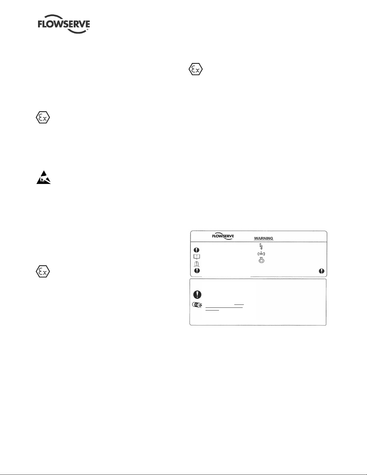
1.7.2 Safety labels
J218JZ250
ESSENTIAL PROCEEDURES BEFORE STARTING:
INSTALL AND OPERATE EQUIPMENT IN
ACCORDAND WITH THE INSTRUCTION
MANUAL SUPPLIED SEPARATELY.
ENSURE GUARDS ARE SECURELY IN
PLACE.
ENSURE CORRECT DIRECTION OF
ROTATION.
ENSURE CORRECT DRIVER DIRECTION
OR ROTATION WITH COUPLING
ELEMENT / PINS REMOVED: OTHERWISE
SERIOUS DAMAGE MAY RESULT.
VERIFIER LE SENS CORRECT DE
ROTATION DU MOTEUR. POMPE
DESACCOUPLEE / ENTRETOISE
DEMONTEE. NE PAS SUIVRE CETTE
RECOMMANDATION PEUT CONDUIRE A
DE GRAVES DOMMAGES POUR LA POMPE
CDC: 603 604 610 612 621 623 624
ENSURE ALL EXTERNAL CONNECTIONS TO
THE PUMP / SHAFT SEALING AND DRIVER
ARE CONNECTED AND OPERATIONAL
FULLY PRIME UNIT AND SYSTEM.
DO NOT RUN UNIT DRY
FAILURE TO FOLLOW THESE PR OCEEDURES
MAY RESULT IN PERSONAL INJURY
AND/ OR EQUIPMENT DAMAGE
J218JZ250
KONTROLLE VORGESCHRIEBENER
DREHRICHTUNG ! HIERZU
KUPPLUNGSZWISCHENSTÜCK /
KUPPLUNGSBOLZEN ENTFERNEN.
ANDERENFALLS ERNSTHAFTE SC HÄDEN !
ZORG VOOR JUISTE ROTATIERICHTING
VAN DRIJFAS WAARBIJ DE
KOPPELELELMENTEN / PENNEN
VERWIJDERD ZIJN: VERZUM KAN
ERNSTIGE SCHADE TOT GEVOLG HABBEN.
1.8 Specific machine performance
For performance parameters see section 1.5, Duty
conditions. Where performance data has been
supplied separately to the purchaser these should be
obtained and retained with these User Instructions if
required
.
Page 7
Page 8

ESP3 USER INSTRUCTIONS ENGLISH 26999943 08-11
of 64
1.9 Noise level
Attention must be given to the exposure of personnel
to the noise, and local legislation will define when
guidance to personnel on noise limitation is required,
and when noise exposure reduction is mandatory.
This is typically 80 to 85 dBA.
The usual approach is to control the exposure time to
the noise or to enclose the machine to reduce emitted
sound. You may have already specified a limiting
noise level when the equipment was ordered,
however if no noise requirements were defined, then
attention is drawn to the following table to give an
indication of equipment noise level so that you can
take the appropriate action in your plant.
Pump noise level is dependent on a number of
operational factors, flow rate, pipe work design and
acoustic characteristics of the building, and so the
values given are subject to a 3 dBA tolerance and
cannot be guaranteed.
Similarly the motor noise assumed in the “pump and
and high efficiency motors when on load directly
driving the pump. Note that a motor driven by an
inverter may show an increased noise at some
speeds.
If a pump unit only has been purchased for fitting with
your own driver then the “pump only” noise levels in
the table should be combined with the level for the
driver obtained from the supplier. Consult Flowserve
or a noise specialist if assistance is required in
combining the values.
It is recommended that where exposure approaches
the prescribed limit, then site noise measurements
should be made.
The values are in sound pressure level LpA at 1 m
(3.3 ft) from the machine, for “free field conditions
over a reflecting plane”. The values are
representative of a non-submerged wet end.
For estimating sound power level LWA (re 1 pW) then
add 14 dBA to the sound pressure value.
motor” noise is that typically expected from standard
Motor size
and speed
kW (hp)
<0.55(<0.75) 72 72 64 65 62 64 62 64
0.75 (1) 72 72 64 66 62 64 62 64
1.1 (1.5) 74 74 66 67 64 64 62 63
1.5 (2) 74 74 66 71 64 64 62 63
2.2 (3) 75 76 68 72 65 66 63 64
3 (4) 75 76 70 73 65 66 63 64
4 (5) 75 76 71 73 65 66 63 64
5.5 (7.5) 76 77 72 75 66 67 64 65
7.5 (10) 76 77 72 75 66 67 64 65
11(15) 80 81 76 78 70 71 68 69
15 (20) 80 81 76 78 70 71 68 69
18.5 (25) 81 81 77 78 71 71 69 71
22 (30) 81 81 77 79 71 71 69 71
30 (40) 83 83 79 81 73 73 71 73
37 (50) 83 83 79 81 73 73 71 73
45 (60) 86 86 82 84 76 76 74 76
55 (75) 86 86 82 84 76 76 74 76
75 (100) 87 87 83 85 77 77 75 77
90 (120) 87 88 83 85 77 78 75 78
110 (150) 89 90 85 87 79 80 77 80
150 (200) 89 90 85 87 79 80 77 80
200 (270)
300 (400) 87 90 85 86
`1 The noise level of machines in this range will most likely be of values which require noise exposure control, but typical values are
inappropriate.
Note: for 1 180 and 960 r/min reduce 1 450 r/min values by 2 dBA. For 880 and 720 r/min reduce 1 450 r/min values by 3 dBA.
Pump
only
1 1 1 1
Typical sound pressure level LpA at 1 m reference 20 µPa, dBA
3 550 r/min 2 900 r/min 1 750 r/min 1 450 r/min
Pump and
motor
Pump
only
Pump and
motor
Pump
only
85 87 83 85
Pump and
motor
Pump
only
Pump and
motor
Page 8
Page 9
ESP3 USER INSTRUCTIONS ENGLISH 26999943 08-11
of 64
2 TRANSPORT AND STORAGE
2.1 Consignment receipt and unpacking
Immediately after receipt of the equipment it must be
checked against the delivery/shipping documents for
its completeness and that there has been no damage
in transportation. Any shortage and/or damage must
be reported immediately to Flowserve Pump Division
and must be received within ten days of receipt of the
equipment. Later claims cannot be accepted.
Check any crate, boxes or wrappings for any
accessories or spare parts that may be packed
separately with the equipment or attached to
sidewalls of the box or equipment.
Each product has a unique serial number. Check
that this number corresponds with that advised and
always quote this number in correspondence as well
as when ordering spare parts or further accessories.
2.2 Handling
Boxes, crates, pallets or cartons may be unloaded
using forklift vehicles or slings dependent on their
size and construction.
2.3 Lifting
Pumps and motors often have integral
lifting lugs or eye bolts. These are intended for use in
only lifting the individual piece of equipment.
Do not use or cast-in lifting lugs to lift
pump, motor and mounting plate assemblies.
Care must be taken to lift components
or assemblies above the center of gravity to prevent
the unit from flipping.
Carefully sling ESP pumps so that
bearing lubrication lines [3840.1] will not be bent or
damaged when lifting.
It is advisable to raise the pump into the vertical
position before uncrating. If this isn't possible, pumps
over eight feet long must be supported at more than
one place when raising to the vertical position. Use a
support strap around the bottom column [1341.2] and
on the motor support [3160]. Or lift use optionally
supplied lifting eyes [6820] installed on mounting
plate [6130].
2.4 Storage
Store the pump in a clean, dry location
away from vibration. Leave flange covers in place to
keep dirt and other foreign material out of pump
casing. Turn the pump shaft at regular intervals to
prevent brinelling of the bearings and the seal faces,
if fitted, from sticking.
The pump may be stored as above for up to 6
months. Consult Flowserve for preservative actions
when a longer storage period is needed.
2.4.1 Short term storage and packaging
Normal packaging is designed to protect the pump
and parts during shipment and for dry, indoor storage
for up to six months or less. The following is an
overview of our normal packaging:
• All loose un-mounted items are packaged in a
water proof plastic bag and secured to the pallet.
• Inner surfaces of the bearing housing, shaft (area
through bearing housing) and bearings are coated
with Cortec VCI-329 rust inhibitor, or equal.
Bearing housings are not filled with oil
prior to shipment
• Regreasable bearings are packed with grease
• The internal surfaces of ferrous casings, covers,
flange faces, and the impeller surface are
sprayed with Cortec VCI-389, or equal
• Exposed shafts are taped with Polywrap
• Flange covers are secured to both the suction
and discharge flanges
• In some cases with assemblies ordered with
external piping, components may be
disassembled for shipment
• The pump must be stored in a covered, dry
location
2.4.2 Long term storage and packaging
Long term storage is defined as more than six
months, but less than 12 months. The procedure
Flowserve follows for long term storage of pumps is
given below. These procedures are in addition to the
short term procedure.
• Each assembly is hermetically (heat) sealed from
the atmosphere by means of tack wrap sheeting
and rubber bushings (mounting holes)
• Desiccant bags are placed inside the tack
wrapped packaging
• A solid wood box is used to cover the assembly
This packaging will provide protection for up to twelve
months from humidity, salt laden air, dust etc.
Page 9
Page 10
ESP3 USER INSTRUCTIONS ENGLISH 26999943 08-11
of 64
After unpacking, protection will be the responsibility of
the user. If units are to be idle for extended periods
after addition of lubricants, inhibitor oils and greases
should be used. Every three months, the pump shaft
should be rotated approximately 10 revolutions.
2.5 Recycling and end of product life
At the end of the service life of the product or its
parts, the relevant materials and parts should be
recycled or disposed of using an environmentally
acceptable method and in accordance with local
regulations. If the product contains substances that
are harmful to the environment, these should be
removed and disposed of in accordance with current
local regulations. This also includes the liquids
and/or gases that may be used in the "seal system"
or other utilities.
Make sure that hazardous substances are
disposed of safely and that the correct personal
protective equipment is used. The safety
specifications must be in accordance with the current
local regulations at all times.
3 DESCRIPTION
3.1 Configurations
The ESP3 vertical immersion sump pumps are
separately coupled metallic construction single stage
centrifugal pumps for wet pit applications. The ESP3
wetted parts are available in a wide range of
materials to handle most fluids. Vapor-tight, vaporproof, and pressurized construction options are
available. The hydraulics utilized are from Mark 3
chemical process pumps.
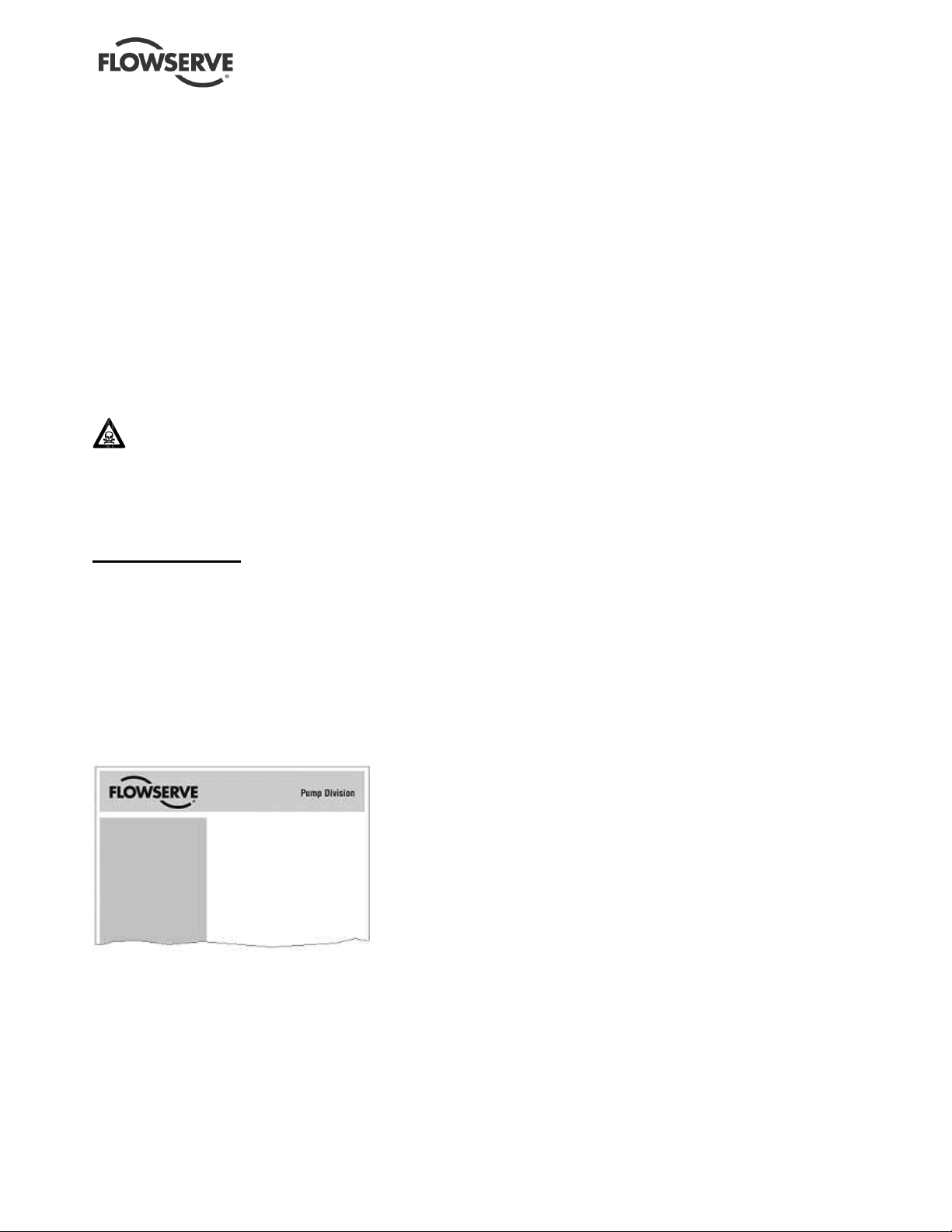
Figure 3-1: Nameplate mounted to housing
3.2 Nomenclature
The pump size will be engraved on the nameplate
typically as below:
2 E 6 X 4 SP - 13 A /12.5 RV
• Frame size
“2" indicates a medium size pump frame (in this
example, a Group 2)
1 = Group 1 (small frame)
2 = Group 2 (medium frame)
3 = Group 3 (large frame)
• Power end
E = ESP3 Pump
• “6” = nominal suction port size (in.)
• “4” = Nominal discharge port size (in.)
• Modifier for “specialty pumps”
SP = standard sump pump
RSP = recessed impeller pump
LFSP = Lo-Flo pump
• Nominal maximum impeller diameter. “13” = 13 in.
• Pump design variation
A = This pump has been redesigned from an earlier
version. The impeller and casing are no longer
interchangeable with the earlier version.
H = This pump is designed for a higher flow capacity
than another pump with the same basic
designation. (Examples: 4X3-10 and 4X3-10H;
6X4-10 and 6X4-10H; 10X8-16 and 10X8-16H.
HH = This pump is designed for a higher head than
another pump with the same basic designation.
(Example: 4X3-13 and 4X3-13HH.)
• Actual impeller size
“12.5” = 12 ½ in. diameter; 8.13 = 8 ⅛ in.;
10.75 = 10 ¾ in.
(Previous annotation: 124 = 12 4/8 or 12 ½ in.
diameter; 83 = 8 ⅜ in.)
• Impeller style
RV = reverse vane impeller; OP = Open impeller
Serial No.
Equipment No.
Purchase Order
Material
Date DD/MMM/YY
Page 10
Model
Size
MDP
2E6X4 SP-13A/12.5 RV
Page 11

ESP3 USER INSTRUCTIONS ENGLISH 26999943 08-11
of 64
3.3 Design of major parts
3.3.1 Pump casing
As used by the Mark 3 Product Line. Depending upon
the installation, the casing feet may have been
removed. Axial bolting retains the casing to the cover
and compresses the sealing gasket.
3.3.2 Impeller
Depending on the product, the impeller is either reverse
vane or open. The impeller is threaded to the end of the
shaft
3.3.3 Shaft/sleeve
Solid and sleeved shafts are available. The shaft is
threaded on the impeller end and keyed on the drive
end.
3.3.4 Pump bearings and lubrication
The external thrust bearing is a grease-lubricated
duplex angular contact ball bearing. The radial load
line bearings are sleeve plain bearings lubricated by
product, external flush or grease.
3.3.5 Bearing housing
The external housing contains grease ports and is
sealed with lip seals.
3.3.6 Cover plate
The cover plate has a spigot (rabbet) fit between the
pump casing and adapter for optimum concentricity.
The cover plate holds the throttle bushing at the back
of the impeller.
3.3.7 Shaft seal
There is no shaft seal required near the impeller
since the pump is submerged. Only a small amount
of pressurized fluid escapes through controlled leak
paths from the backside of the impeller. Packing or a
mechanical seal can be fitted above the sump level to
provide vapor proof or pressurized options for the
application.
3.3.8 Driver
The standard driver is a NEMA C-Face vertical electric
motor. The motor must be equipped with a drip-cap
when installed outdoors.
3.3.9 Accessories
Accessories may be fitted when specified by the
customer.
3.4 Performance and operation limits
This product has been selected to meet the
specification of your purchase order. See section 1.5.
The following data is included as additional information
to help with your installation. It is typical, and factors
such as liquid being pumped, temperature, material of
construction, and seal type may influence this data. If
required, a definitive statement for your application can
be obtained from Flowserve.
3.4.1 Alloy cross reference chart
Figure 3-3 is the Alloy cross-reference chart. The
chart is used to material group number which can be
used to establish the pressure-temperature rating as
discussed below. Not all materials may be available
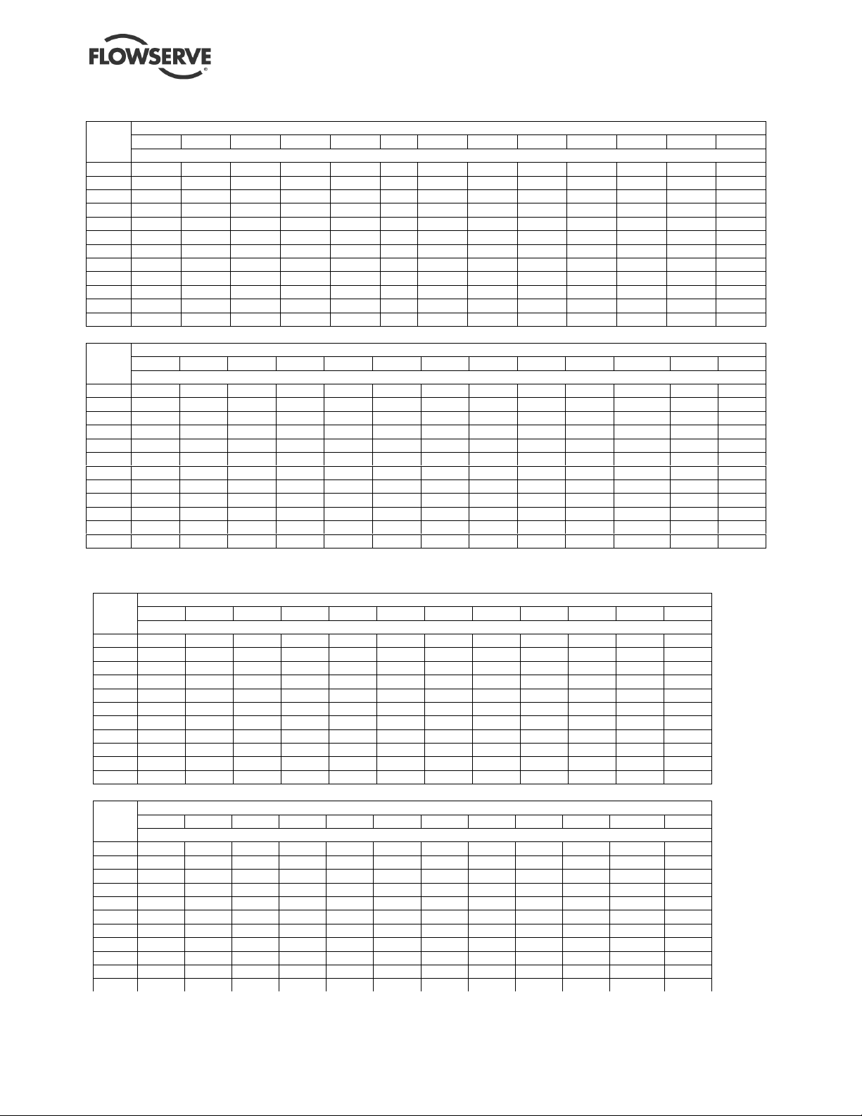
3.4.2 Pressure-temperature ratings
The pressure–temperature (P-T) ratings for ESP3
pumps are shown in figures 3-4 and 3-5. Determine
the appropriate casing “Material Group No.” in Figure
3-3. Interpolation may be used to find the pressure
rating for a specific temperature.
Example:
The pressure temperature rating for a standard GP210” pump with Class 150 flanges and CF8M
construction at an operating temperature of 149˚C is
found as follows:
a) The correct pressure-temperature chart is Figure
3-4.
b) From Figure 3-3, the correct material group for
CF8M is 2.2
c) From Figure 3-4, the pressure-temperature rating
is 14.8 bar.
The maximum discharge pressure must be less
than or equal to the P-T rating. Discharge pressure
may be approximated by adding the suction pressure
and the differential head developed by the pump.
3.4.3 Suction pressure limits
Pump suction pressure is limited by the maximum pump
length and the maximum sump pressure of 3.45 bar (50
psi).
3.4.4 Minimum continuous flow
The minimum continuous flow (MCF) is based on a
percentage of the best efficiency point (BEP).
Figure 3-2 identifies the MCF for all ESP3 pump
models with the exception of the Lo-Flo pump line;
there is no MCF associated with this product line.
Page 11
Page 12

ESP3 USER INSTRUCTIONS ENGLISH 26999943 08-11
of 64
Figure 3-2: Minimum continuous flow
Pump size
1E3x2SP-62 20% 10% 10%
2E3x2SP-82 20% 10% 10%
2E4x3SP-82 20% 10% 10%
2E3x2SP-10A 30% 10% 10%
2E4x3SP-10 30% 10% 10%
2E6x4SP-10 40% 10% 10%
2E6x4SP-10H n.a. 20% 10%
2E3x1.5SP-13 30% 10% 10%
2E3x2SP-13 40% 10% 10%
2E4x3SP-13 40% 20% 10%
2E4x3SP-13HH n.a. 50% 30%
2E6x4SP-13A 60% 40% 10%
3E8x6SP-14A n.a. 40% 15%
3E10x8SP-14 n.a. 40% 10%
3E6x4SP-16 n.a. 50% 10%
3E8x6SP-16 n.a. 50% 10%
3E10x8SP-16 n.a. 50% 10%
All other sizes 10% 10% 10%
3500/2900
r/min
MCF % of BEP
1750/1450
r/min
1180/960
r/min
Figure 3-3: Alloy cross-reference chart
Flowserve
Material Code
E3020 Ductile iron DCI A395, Gr. 60-40-18 1.0
C3009 Carbon steel DS A216 Gr. WCB 1.1
C3062 304 D2 A744, Gr. CF8 2.1
C3069 304L D2L A744, Gr. CF3 2.1
C3063 316 D4 A744, Gr. CF8M 2.2
C3067 316L D4L A744, Gr. CF3M 2.2
C4029 Durcomet 5 DV None 2.2
C3107 Duplex Stainless CD4M A995, Gr. CD4MCuN 2.8
C4028 Alloy 20 D20 A744, Gr. CN7M 3.17
K3008 Nickel DNI A494, Gr. CZ100 3.2
K3007
K3005
K4007
K4008
D4036 Durco DC8 DC8 None H3004 Titanium Ti B367, Gr. C3 Ti
H3005 Titanium-Pd TiP B367, Gr. C8A Ti
H3007 Zirconium Zr B752, Gr. 702C Ti
E3033 High chrome iron CR28 A532 class 3 Cr
E4027 High chrome iron CR29 None Cr
E4028 High chrome iron CR35 None Cr
Duriron, Durichlor 51 and Superchlor are registered trademarks of Flowserve Corporation.
Hastelloy is a registered trademark of Haynes International, Inc.
Inconel and Monel are registered trademarks of International Nickel Co. Inc.
Generic
Designation
Monel400
Inconel600
HastelloyB
HastelloyC
Durco Legacy
DMM A494, Gr. M35-1 3.4
DINC A494, Gr. CY40 3.5
DC2 A494, Gr. N7M 3.7
DC3 A494, Gr. CW6M 3.8
Codes
ASTM
Specifications
Material
Group No.
Page 12
Page 13
ESP3 USER INSTRUCTIONS ENGLISH 26999943 08-11
of 64
700 325 266 269
277 313 342 342 144
Figure 3-4 Class 150 Flanges
Material Group No.
˚C
-73 19.0 19.0 19.7 15.9 9.7 15.9 15.2 20.0 20.0 20.0
-29 17.2 19.7 19.0 19.0 19.7 15.9 9.7 15.9 15.2 20.0 20.0 20.0
-18 17.2 19.7 19.0 19.0 19.7 15.9 9.7 15.9 15.2 20.0 20.0 20.0 12.6
38 17.2 19.7 19.0 19.0 19.7 15.9 9.7 15.9 15.2 20.0 20.0 20.0 12.6
93 16.2 17.9 15.9 16.2 17.9 13.8 9.7 13.8 13.8 17.9 17.9 17.9 12.6
149 14.8 15.9 14.1 14.8 15.9 12.4 9.7 13.1 12.4 15.9 15.9 15.9 12.6
171 14.4 15.0 13.7 14.3 15.0 11.9 9.7 13.0 12.1 15.0 15.0 15.0 12.6
204 13.8 13.8 13.1 13.4 13.8 11.0 9.7 12.8 11.7 13.8 13.8 13.8
260 11.7 11.7 11.7 11.7 11.7 10.3 9.7 11.7 11.0 11.7 11.7 11.7
316 9.7 9.7 9.7 9.7 9.7 9.7 9.7 9.7 9.7 9.7 9.7 9.7
343 8.6 8.6 8.6 8.6 8.6 8.6 8.6 8.6 8.6
371 7.6 7.6 7.6 7.6 7.6 7.6 7.6 7.6
1.0 1.1 2.1 2.2 2.8 3.17 3.2 3.4 3.5 3.7 3.8 Ti Cr Temp
bar
Material Group No.
˚F
-100 275 275 285 230 140 230 220 290 290 290
-20 250 285 275 275 285 230 140 230 220 290 290 290
100 250 285 275 275 285 230 140 230 220 290 290 290 183
200 235 260 230 235 260 200 140 200 200 260 260 260 183
300 215 230 205 215 230 180 140 190 180 230 230 230 183
340 209 218 199 207 218 172 140 188 176 218 218 218 183
400 200 200 190 195 200 160 140 185 170 200 200 200
500 170 170 170 170 170 150 140 170 160 170 170 170
600 140 140 140 140 140 140 140 140 140 140 140 140
650 125 125 125 125 125 125 125 125 125
700 110 110 110 110 110 110 110 110
1.0 1.1 2.1 2.2 2.8 3.17 3.2 3.4 3.5 3.7 3.8 Ti Cr Temp
psi
0 250 285 275 275 285 230 140 230 220 290 290 290 183
Figure 3-5 Group2-13” Lo-Flo Pumps with Class 300 Flanges
Material Group No.
˚C
-73 31.0 31.0 31.0 24.1 17.4 24.1 27.6 31.0 31.0 31.0
-29 31.0 31.0 31.0 31.0 31.0 24.1 17.4 24.1 27.6 31.0 31.0 31.0
-18 31.0 31.0 31.0 31.0 31.0 24.1 17.4 24.1 27.6 31.0 31.0 31.0
38 31.0 31.0 31.0 31.0 31.0 24.1 17.4 24.1 27.6 31.0 31.0 31.0
93 29.1 28.3 25.9 26.7 29.8 20.9 17.4 21.3 26.1 31.0 31.0 27.5
149 27.4 27.5 23.3 24.1 27.5 18.7 17.4 19.9 24.4 30.2 30.2 24.0
204 25.5 26.6 21.3 22.2 25.4 16.9 17.4 19.3 22.7 29.2 29.2 20.5
260 24.0 25.2 19.7 20.7 23.8 15.7 17.4 19.1 22.1 27.5 27.5 17.0
316 22.5 23.1 18.7 19.4 23.0 14.5 17.4 19.1 21.9 25.0 25.0 13.4
343 21.8 22.4 18.5 19.2 19.1 21.8 24.4 24.4 11.7
371 22.4 18.3 18.5 19.1 21.6 23.6 23.6 9.9
1.0 1.1 2.1 2.2 2.8 3.17 3.2 3.4 3.5 3.7 3.8 Ti Temp
bar
Material Group No.
˚F
-100 450 450 450 350 252 350 400 450 450 450
-20 450 450 450 450 450 350 252 350 400 450 450 450
100 450 450 450 450 450 350 252 350 400 450 450 450
200 422 410 375 388 432 303 252 309 379 450 450 399
300 397 398 338 350 399 271 252 289 354 438 438 348
400 369 386 309 322 369 245 252 280 330 423 423 297
500 348 365 285 300 345 228 252 277 320 399 399 246
600 327 334 272 281 333 210 252 277 318 363 363 195
650 316 325 269 278 277 316 354 354 170
1.0 1.1 2.1 2.2 2.8 3.17 3.2 3.4 3.5 3.7 3.8 Ti Temp
psi
0 450 450 450 450 450 350 252 350 400 450 450 450
Page 13
Page 14

ESP3 USER INSTRUCTIONS ENGLISH 26999943 08-11
of 64
3.4.5 Minimum suction pipe submergence
The minimum submergence is shown in Figure 3-6.
Figure 3-6
Minimum submergence (meters)
Flow (m3/hr.) Suct.
Size
1.5 0.30 0.55 1.07 2.65
2 0.30 0.58 1.40 2.74
3 0.30 0.79 1.52 2.38
4 0.30 0.55 1.07 2.13
6 0.43 .076 1.19 1.83
8 0.55 0.94 1.19 1.65
10 0.64 0.85 1.22 1.52
Minimum submergence (feet)
Size
1.5 1.0 1.8 3.5 8.7
2 1.0 1.9 4.6 9.0
3 1.0 2.6 5.0 7.8
4 1.0 1.8 3.5 7.0
6 1.4 2.5 3.9 6.0
8 1.8 3.1 3.9 5.4
10 2.1 2.8 4.0 5.0
6.8 11.4 20.5 45.5 79.5 136 273 341 500 568 727 1023 1250
Flow (USgpm) Suct.
30 50 90 200 350 600 1200 1500 2200 2500 3200 4500 5500
Page 14
Page 15

ESP3 USER INSTRUCTIONS ENGLISH 26999943 08-11
of 64
3.4.6 ESP3 Bearing Materials
• CARBON - Carbon graphite, especially developed
for sump pump applications, is chemically inert. The
self-lubricating properties of graphite present in
the carbon bearings enhance its dry running
capabilities.
• BRONZE - SAE 660 Bronze (grooved when
grease lubricated).
• CAST IRON - ASTM A48 Class 30 iron (grooved
when grease lubricated).
• RUBBER - Resilient compounded rubber, fluted to
allow abrasives to wash away.
• TEFLON - Fiberglass & molybdenum disulphide
filled, with low cold flow, high tensile and
elongation characteristics.
• ARHT - Chemical and wear resistant bearing
material developed by Greene, Tween & Co.
(grooved when grease lubricated).
All bearing materials are enclosed in an AISI-316
shell (ex. Bronze, Cast Iron & ARHT). Higher
alloys are available (grooved when grease
lubricated).
• VITON - Resilient Viton, fluted to allow handling of
dirty corrosive liquids not able to be handled by
carbon or rubber.
Figure 3-7: ESP3 Bearing selection
Bearing Material Max Temp Liquid Pumped Lubricant Shaft Material
Most clean acids,
Carbon
Bronze
Cast Iron
Rubber
Teflon
Teflon
Viton
ARHT
ARHT
177˚C
350˚F
82˚C
180˚F
82˚C
180˚F
71˚C
160˚F
177˚C
350˚F
Liquid Lube
82˚C
180˚F
Grease Lube
149˚C
300˚F
121˚C
250˚F
Liquid Lube
82˚C
180˚F
Grease Lube
general chemicals,
water, cleaning fluids,
gasoline, kerosene, jet
Water and compatible
Water and compatible
liquids including alkaline
General abrasive liquids
compatible with rubber
compatible with carbon
compatible with carbon
compatible with carbon
Dirty acids, hot water
compatible with PEEK
chemicals compatible
fuels
liquids
caustics
Clean acids not
Clean acids not
Dirty acids not
or rubber
and chemicals
Dirty acids and
with PEEK
External flush
Product Lube
External flush
Product Lube
Grease Lube
External flush
Product Lube
Grease Lube
External flush
Product Lube
External flush
Product Lube
Grease SS only
External flush
Product Lube
External flush
Product Lube
Grease SS only
Steel or SS
Steel or SS
Steel only
Steel only
Steel only
Steel
Steel
Steel
SS only
SS only
SS only
SS only
SS only
SS only
SS only
SS only
Page 15
Page 16

ESP3 USER INSTRUCTIONS ENGLISH 26999943 08-11
of 64
Figure 3-8: Engineering information
Pump Group Size GP1 – 1E GP2 – 2E GP3 – 3E
Ball Bearing Size
1st Critical Speed @ 3550 span
1st Critical Speed @ 1750 span
1st Critical Speed @ 1180 span
Std. Bearing Span @ 3550 rpm
Std, Bearing Span @ 1750 rpm
Standard Bearing Span @
1180 rpm
Shaft Diameter @ Sleeve
Bearing
Shaft Diameter @ Stuffing Box
Shaft Diameter @ Coupling
Keyway Size mm (in)
Nominal Impeller Clearance
Corrosion Allowance
Minimum Pit Depth
Maximum Pit Depth
28.58 mm (1.125 in.) 38.10 mm (1.500 in.) 53.98 mm (2.125 in.)
28.58 mm (1.125 in.) 38.10 mm (1.500 in.) 47.63 mm (1.875 in.)
25.4 mm (1.000 in.) 34.93 mm (1.375 in.) 41.28 mm (1.625 in.)
6.4 x 3.2 (1/4 x 1/8) 7.9 x 4.0 (5/16 x 5/32) 15.9 x 7.9 (5/8 x 5/16)
7308 7310 7313
6000 5555 n.a.
2344 2469 2833
2344 2469 2833
760 mm (30 in.) 915 mm (36 in.) n.a.
1220 mm (48 in.) 1220 mm (48 in.) 1520 mm (60 in.)
1220 mm (48 in.) 1220 mm (48 in.) 1520 mm (60 in.)
.46 mm (0.018 in.) .46 mm (0.018 in.) .64 mm (0.025 in.)
3.2 mm (0.125 in.) 3.2 mm (0.125 in.) 3.2 mm (0.125 in.)
.61 m (2.0 ft) .61 m (2.0 ft) .91 m (3.0 ft)
6.10m (20.0 ft) 6.10 m (20.0 ft) 6.10 m (20.0 ft)
Page 16
Page 17

ESP3 USER INSTRUCTIONS ENGLISH 26999943 08-11
of 64
4 INSTALLATION
INSTALLATION AND START-UP CHECKLIST
1. Check that the sump design will keep the
liquid level within the proper range.
2. Check that the pump location is accessible and
has adequate ventilation.
3. Verify that the pump and motor are suitable for
the pump environment.
4. Check the sump design to be sure it is adequate
to support the complete pumping assembly.
5. Verify the discharge piping meets Hydraulic
Institute Standards for design and is properly
supported.
6. Install the suction strainer
7. Install the liquid level controls.
8. If pump was ordered for vapor proof or
pressurized design, install sealing device.
9. Lift the pump into place and tighten the mounting
plate bolts.
10. Install the motor on the pump, but do not connect
the coupling or electric power.
11. Connect the wiring to the liquid level
indicators and pump controls, as required.
12. Connect the discharge piping,
13. Check that all auxiliary piping is connected
14. Verify the pump is free of pipe strain by
turning the shaft by hand.
15. Verify the impeller setting.
16. Lubricate the driver and pump as required
using approved lubricants.
1 _________ __________
2 _________ __________
3 _________ __________
4 _________ __________
5 _________ __________
6 _________ __________
7 _________ __________
8 _________ __________
9 _________ __________
10 _________ __________
11 _________ __________
12 _________ __________
13 _________ __________
14 _________ __________
15 _________ __________
16 _________ __________
17 _________ __________
17. Connect the wiring for the motor.
18. Turn power ON and jog the driver to verify proper
rotation; clockwise looking down.
19. Turn power OFF and install the coupling element
and coupling guard. Then turn power ON, but do
not start the driver.
Page 17
18 _________ __________
19_________ __________
Page 18

ESP3 USER INSTRUCTIONS ENGLISH 26999943 08-11
of 64
4.1 Location
The pump should be located to allow room for
installation, access, ventilation, maintenance, and
inspection with ample headroom for lifting. Refer to
the general arrangement drawing for the pump set.
If pump is furnished with external flush-lubricated
bearings, the fluid lines must be accessible from
the pump location.
Also important, especially in the larger flow units, is
proper sump design. Liquid velocity approaching
the pump should be one foot per second or less.
When more than one pump is installed and used at
the same time in the same sump, the location and
spacing of the pumps are important. The
guidelines for sump design and pump placement as
outlined in the "Hydraulic Institute Standards" are
recommended.
4.2 Part assemblies
• Pumps are shipped completely assembled
except for driver, strainer [6531], float controls
(if furnished), pit cover, and the mechanical
seal [4200] or packing [4130] for the stuffing
box on a vapor proof or pressurized design
pump.
• When mechanical seals are furnished, they
should be installed before the motor is put in
place. Refer to seal installation instructions in
section 6.9.5.
• Vapor Proof and Pressurized design pumps
are furnished with an upper stuffing box
[4110]. If the stuffing box doesn't already have
the packing [4130] or seal [4200] installed,
then they should be installed before the motor
is mounted. See section 6.
• The driver will be mounted after the pump is
installed.
• When the pump is shipped, all threads and all
openings are covered. This protection should
not be removed until installation. If the pump
is removed from service, this protection should
be reinstalled.
4.3 Foundation
There should be adequate space for workers to
install, operate, and maintain the pump. The
foundation should be sufficient to absorb any
vibration and should provide a rigid support for the
pump and motor. Recommended mass of a
concrete foundation should be three times that of
the pump, motor and mounting plate. Supporting
members must be sufficiently strong to prevent
spring action and/or lateral movement.
4.4 Pump Mounting
The pump may be mounted directly on the pit
using the pump mounting plate [6130] or in
conjunction with a pit cover.
a) The pump was checked during assembly at
the factory to make sure the pump shaft [2100]
rotated freely by hand. Handling during
shipment, storage, or preparation for
installation could have caused distortions
resulting in pump shaft binding. Check the
shaft to make sure that it will rotate freely by
hand.
b) Check all bolts and nuts for tightness, then
carefully lower the assembled pump into the
pit, taking care not to damage lube lines or float
control equipment. Make sure that any
equipment used to lift the pump or any of
its components is capable of supporting the
weights encountered. Make sure that all parts
are properly rigged before attempting to lift.
c) Pump mounting plate and/or pit cover must
maintain level within 1/8in/ft. from one side of
the plate to the other, and be supported evenly
at all points before being bolted down.
d) If the sump doesn't provide a level mounting
surface for the pump, drive wedges under
the mounting plate/pit cover until pump levels
out. The wedges must be able to support the
weight of the entire pumping assembly and
hold the assembly steady enough that no
excess vibration occurs.
e) Do not bolt the discharge flange of the pump
to the piping until the baseplate foundation is
completely installed.
f) Run piping to the discharge of the pump.
There should be no piping loads transmitted to
the pump after connection is made.
4.5 Mechanical seals and packing
Pumps supplied with vapor proof construction or
pressurized designs are furnished with an upper
stuffing box [4110] equipped to take mechanical
seals or packing (see vapor proof and pressurized
design cross-sections in section 8). Gas seals are
typically of a canister design, thus the stuffing box
is omitted. The canister seals are mounted directly
to the upper column [1341.1]. Installation
instructions can be found in section 6.9.5
4.5.1 Mechanical seal
Mechanical seals [4200] are typically installed prior
to shipment. Specific order requirements may
specify that the seal be shipped separately, or none
be supplied. It is the pump installer’s responsibility
to determine if a seal was installed. Installation
instruction can be found in section 6
Page 18
Page 19
of 64
Failure to ensure that a seal is installed may
result in serious leakage of vapor and of the pumped
fluid.
Seal and seal support system must be installed and
operational as specified by the seal manufacturer.
The stuffing box/seal chamber/gland may have
ports that have been temporarily plugged at the
factory to keep out foreign matter. It is the
installer’s responsibility to determine if these plugs
should be removed and external piping connected.
Refer to the seal drawings and or the local
Flowserve representative for the proper
connections.
4.5.2 Packing
When the pump is intended to be equipped with
shaft packing, it is NOT Flowserve standard
practice to install the packing in the stuffing box
prior to shipment. The packing is shipped with the
pump. It is the pump installer’s responsibility to
install the packing in the stuffing box. Installation
instructions can be found in section 6.
Failure to ensure that the packing is installed
may result in serious leakage of vapor and of the
pumped fluid.
4.6 Driver Mounting
a) Before the motor is installed, be sure to
connect the motor half coupling hub and the
pump half coupling hub onto their respective
shafts.
b) Carefully lift the motor and place it on the
support head [3160] of the pump.
c) Turn the motor frame to one of the four
positions where the motor bolt holes line up to
the support head [3160]. Select the position of
the motor to suit the desired conduit box
location. Install the motor hold down bolts
[6570.1]. In some instances a motor adapter
[1340.3] may be furnished. In this case the
adapter must be installed before the motor can
be mounted.
d) Motor to pump alignment is controlled by fits
within the adapter and cannot be adjusted.
e) Locate the coupling and source of electrical
power but DO NOT INSTALL THE COUPLING
DRIVE ELEMENT AT THIS TIME.
f) Connect the motor terminals to the leads from
the starter panel. Make sure the motor shaft
and/or coupling is not touching any part of the
pump shaft or pump half coupling. Rotate the
ESP3 USER INSTRUCTIONS ENGLISH 26999943 08-11
motor shaft by hand to make sure it is free to
rotate when energized.
Never check driver rotation unless the
pump and driver shafts are disconnected and
physically separated. Failure to follow this
instruction can result in serious damage to the
pump and driver if rotation is in the wrong
direction.
g) Jog the motor and check for proper rotation
which should be clockwise when looking
down on top of the motor. If rotation is wrong,
interchange any two motor connections on
three-phase motors. On single-phase motors,
follow the motor manufacturer’s instructions. After
changing the connections, again check the rotation
to ensure that the direction is correct.
h) Disconnect and lockout the power supply to the
driver.
i) The coupling can now be fully installed and
join the driver and pump shafts together (see
section 5.4.2).
j) Install the coupling guarding [7450.1-.2] (see
section 5.5).
4.7 Piping
Protective covers are fitted to both the
suction and discharge flanges of the casing and must
be removed prior to connecting the pump to any
pipes.
4.7.1 General piping
If the pump flange(s) have tapped holes, select flange
fasteners with thread engagement at least equal to
the fastener diameter but that do not bottom out in the
tapped holes before the joint is tight.
4.7.2 Suction piping
ESP pumps typically only have strainers attached to
the suction flange of the pump casing. An option for
an extension from the suction flange is available and
is called a tailpipe (see section 8 for cross-sectional
drawing). A tailpipe is useful for applications where
there is adequate NPSH at the lowest sump level but
the discharge pressure is critical and must be
maintained at a maximum value compared to using a
longer column and shaft. Pumps may air-bind if air is
allowed to leak into the piping
Page 19
Page 20
ESP3 USER INSTRUCTIONS ENGLISH 26999943 08-11
of 64
4.7.3 Discharge piping
Install a valve in the discharge line. This valve is
required for regulating flow and/or to isolate the
pump for inspection and maintenance.
When fluid velocity in the pipe is
high, for example, 3 m/s (10 ft/sec) or higher, a
rapidly closing discharge valve can cause a
damaging pressure surge. A dampening
arrangement should be provided in the piping.
All piping must be independently supported,
accurately aligned and preferably connected to the
pump by a short length of flexible piping. The pump
should not have to support the weight of the pipe. It
should be possible to install discharge bolts through
mating flanges without pulling or prying either of the
flanges. All piping must be tight.
a) Use discharge piping one size larger than the
pump discharge.
b) Discharge piping should be well supported
and connected to the pump such that no strain
or weight of the piping is carried by the pump.
c) Check pump shaft for freedom of rotation by
hand to make sure any discharge piping strain
is not causing binding.
d) After the pump discharge, the increaser
should be the first item in the discharge line,
followed by the check valve and gate valve,
respectively. See Figure 4-1.
e) It is recommended that pressure indicating
devices be installed before and after the
valves in the discharge line to verify the pump
is not being run dry and that the discharge
valves are not closed.
Figure 4-1
GATE
VALVE
CHECK
VALVE
CONCENTRIC
INCREASER
PUMP.
DISCHARGE
MOUNTING,
PLATE
The check valve is required to
prevent back-flow through the pump on shut-down.
This flow can reverse rotation of the pump,
potentially damaging the pump, motor and
associated equipment.
Page 20
Page 21

ESP3 USER INSTRUCTIONS ENGLISH 26999943 08-11
of 64
4.7.4 Allowable Nozzle Loads
Discharge piping should be constructed to fit to the
ESP3 discharge piping flange. The ESP3 design
can accommodate large piping loads without
installation should not impose unnecessary loads to
the discharge flange. The allowable piping loads
are shown in Figure 4.2.
affecting the operation of the pump, but the
Figure 4-2 ESP3 Nozzle Loading
Mz
Mz
1
≤+++++
maxmaxmaxmaxmaxmax
Fx
Fx
Fy
Fy
Fz
Fz
Mx
Mx
My
My
Force N Moments Nm
Group Size Fx Fy Fz Mx My Mz
1E 1.5x1LFSP-4 760 1270 760
1E 1.5x1SP-62 760 1270 760
1E 3x1.5SP-62 930 1560 930
1E 3x2SP-62 1110 1870 1110
1E 1.5x1SP-8 760 1270 760
1E 1.5x1LFSP-8 760 1270 760
1E 3x1.5SP-82 930 1560 930
1E 3x2SP-82 1110 1870 1110
2E 3x1.5SP-82 930 1560 930 515 542 515
2E 3x2SP-82 1110 1870 1110
2E 4x3SP-82 1380 2310 1380
2E 2x1SP-10A 760 1270 760
2E 2x1LFSP-10 760 1270 760
2E 3x1.5SP-10 930 1560 930
2E 2x2RSP-10 1110 1870 1110
2E 3x2SP-10 1110 1870 1110
2E 3x3RSP-10 1380 2310 1380
2E 4x3SP-10 1380 2310 1380
2E 4x3SP-10H 1380 2310 1380
2E 6x4SP-10\H 1780 2980 1780
2E 3x1.5SP-13 930 1560 930
2E 3x1.5LFSP-13 930 1560 930
2E 3x2SP-13 1110 1870 1110
2E 4x3SP-13\HH 1380 2310 1380
2E 4x3RSP-13 1380 2310 1380
3E 6x4SP-13A 1780 2980 1780 976 1030 976
3E 6x4RSP-13 1780 2980 1780
3E 8x6SP-14A 2340 3890 2340
3E 10x8SP-14 2800 4670 2800
3E 6x4SP-16\A 1780 2980 1780
3E 8x6SP-16 2340 3890 2340
3E 10x8SP-16\H 2800 4670 2800
414 441 414
414 441 414
515 542 515
610 644 610
414 441 414
414 441 414
515 542 515
610 644 610
610 644 610
759 800 759
414 441 414
414 441 414
515 542 515
610 644 610
610 644 610
759 800 759
759 800 759
759 800 759
976 1030 976
515 542 515
515 542 515
610 644 610
759 800 759
759 800 759
976 1030 976
1281 1356 1281
1539 1620 1539
976 1030 976
1281 1356 1281
1539 1620 1539
Page 21
Page 22

ESP3 USER INSTRUCTIONS ENGLISH 26999943 08-11
of 64
Fx
Fx
Force lbf Moments lbf▪ft
Group Size Fx Fy Fz Mx My Mz
1E 1.5x1LFSP-4 170 285 170 305 325 305
1E 1.5x1SP-62 170 285 170 305 325 305
1E 3x1.5SP-62 210 350 210 380 400 380
1E 3x2SP-62 250 420 250 450 475 450
1E 1.5x1SP-8 170 285 170 305 325 305
1E 1.5x1LFSP-8 170 285 170 305 325 305
1E 3x1.5SP-82 210 350 210 380 400 380
1E 3x2SP-82 250 420 250 450 475 450
2E 3x1.5SP-82 210 350 210 380 400 380
2E 3x2SP-82 250 420 250 450 475 450
2E 4x3SP-82 310 520 310 560 590 560
2E 2x1SP-10A 170 285 170 305 325 305
2E 2x1LFSP-10 170 285 170 305 325 305
2E 3x1.5SP-10 210 350 210 380 400 380
2E 2x2RSP-10 250 420 250 450 475 450
2E 3x2SP-10 250 420 250 450 475 450
2E 3x3RSP-10 310 520 310 560 590 560
2E 4x3SP-10 310 520 310 560 590 560
2E 4x3SP-10H 310 520 310 560 590 560
2E 6x4SP-10\H 400 670 400 720 760 720
2E 3x1.5SP-13 210 350 210 380 400 380
2E 3x1.5LFSP-13 210 350 210 380 400 380
2E 3x2SP-13 250 420 250 450 475 450
2E 4x3SP-13\HH 310 520 310 560 590 560
2E 4x3RSP-13 310 520 310 560 590 560
3E 6x4SP-13A 400 670 400 720 760 720
3E 6x4RSP-13 400 670 400 720 760 720
3E 8x6SP-14A 525 875 525 945 1000 945
3E 10x8SP-14 630 1050 630 1135 1195 1135
3E 6x4SP-16\A 400 670 400 720 760 720
3E 8x6SP-16 525 875 525 945 1000 945
3E 10x8SP-16\H 630 1050 630 1135 1195 1135
Fy
Fy
Fz
Fz
Mx
Mx
My
My
Mz
Mz
1
≤+++++
maxmaxmaxmaxmaxmax
Page 22
Page 23

ESP3 USER INSTRUCTIONS ENGLISH 26999943 08-11
of 64
4.8 Final free rotation check
After connecting the piping, rotate the pump drive
shaft clockwise (viewed from motor end) by hand
several complete revolutions to be sure there is no
binding and that all parts are free. If piping caused
unit to be in a bind, correct piping to relieve strain
on the pump.
4.9 Auxiliary piping
Check to see if any other connections need to be
made to pump, such as fluid injection to stuffing
box for seal or packing lubrication (when furnished)
and make the required connections.
Check to see that connections are made to the
lubrication fittings at pump manifold [3869] on
mounting plate [6130]
4.10 Electrical connections
Electrical connections must be made
by a qualified Electrician in accordance with
relevant local national and international regulations.
It is important to be aware of the EUROPEAN
DIRECTIVE on potentially explosive areas where
compliance with IEC60079-14 is an additional
requirement for making electrical connections.
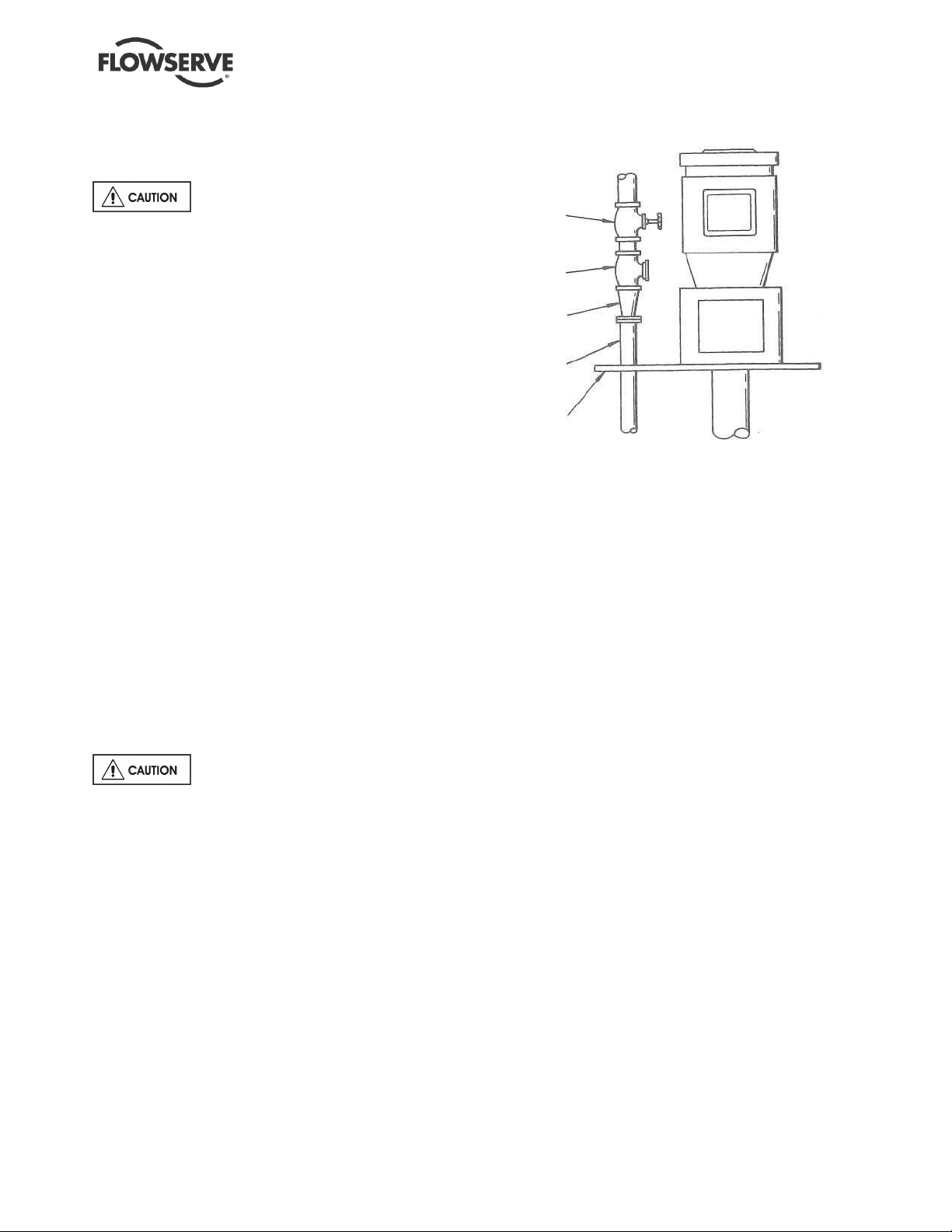
4.11 Level controls
Assemble float control equipment per Figure 4-3
below. Wire the float controls following the
diagrams on the next several pages. The stops
should be set in accordance with maximum and
minimum liquid levels desired and required. Float
rods are furnished in kits of a standard length. The
rod might have to be cut off to fit the particular
installation.
Figure 4-3
It is important to be aware of the EUROPEAN
DIRECTIVE on electromagnetic compatibility when
wiring up and installing equipment on site.
Attention must be paid to ensure that the techniques
used during wiring/installation do not increase
electromagnetic emissions or decrease the
electromagnetic immunity of the equipment, wiring or
any connected devices. If in any doubt contact
Flowserve for advice.
The motor must be wired up in
accordance with the motor manufacturer's
instructions (normally supplied within the terminal
box) including any temperature, earth leakage,
current and other protective devices as appropriate.
The identification nameplate should be checked to
ensure the power supply is appropriate.
See section 5.4, Direction of rotation
before connecting the motor to the electrical supply.
Some of the wiring diagrams are included on the
following pages. If the wiring diagram needed is not
included, contact control manufacturer for wiring
instructions.
Page 23
Page 24
ESP3 USER INSTRUCTIONS ENGLISH 26999943 08-11
of 64
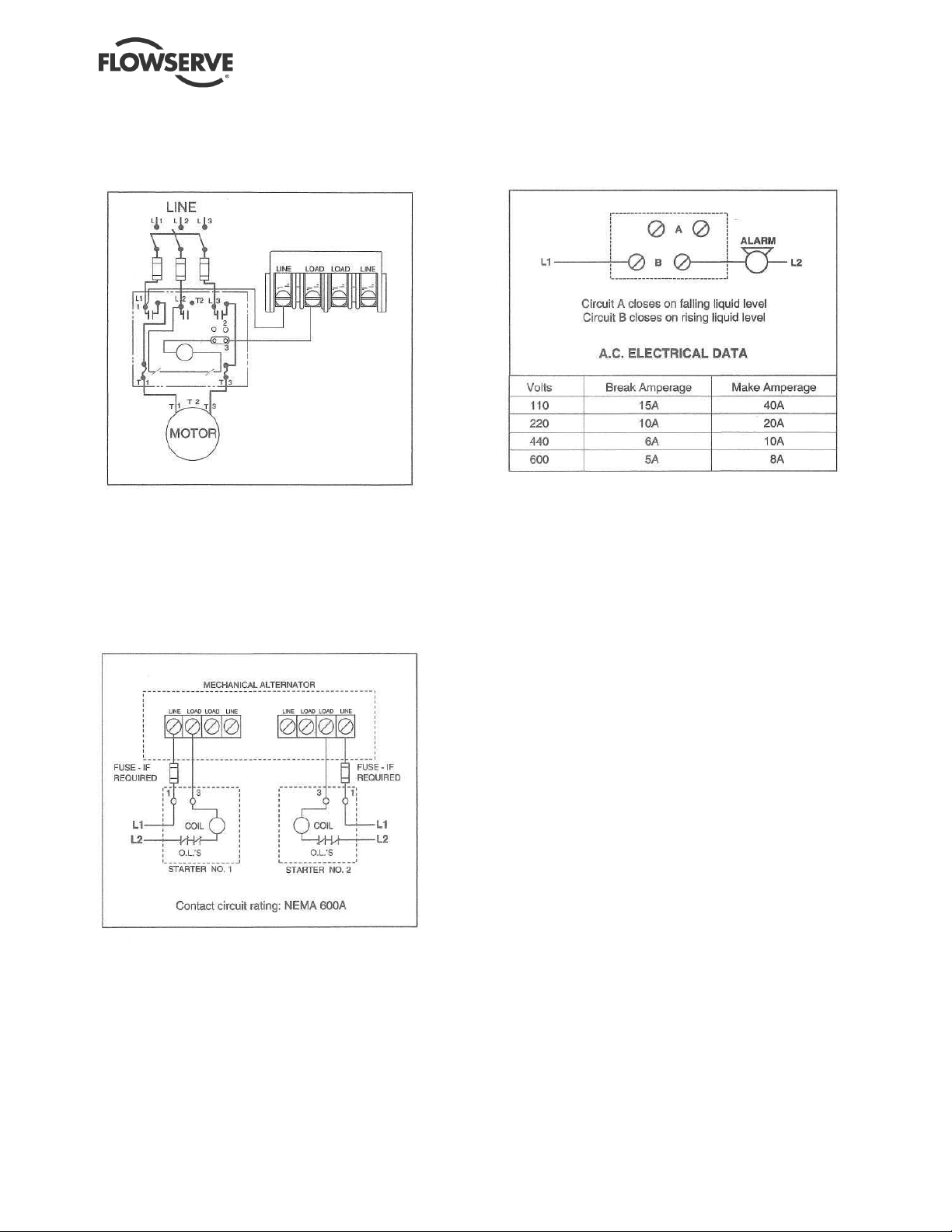
SQUARE "D" CLASS 9036
TYPE GG, DR, DW, GR AND GW - FLOAT SWITCH
(Typical Only)
SQUARE "D" CLASS 9038
TYPE AG, AW, AR - MECHANICAL
ALTERNATOR (Typical Only)
OPTIONAL SQUARE "D" FORM N5
HIGH LEVEL ALARM FOR USE WITH CLASS
9038 MECHANICAL ALTERNATOR (Typical Only)
Page 24
Page 25

ESP3 USER INSTRUCTIONS ENGLISH 26999943 08-11
of 64
MAGNATROL®
FOR SINGLE FUNCTION (A10) SWITCHES
(Typical Only)
MAGNATROL®
FOR DOUBLE FUNCTION (B10) SWITCHES
(Typical Only)
Page 25
Page 26

ESP3 USER INSTRUCTIONS ENGLISH 26999943 08-11
of 64
MAGNATROL®
FOR DOUBLE FUNCTION (B10) SWITCHES
(Typical Only)
Page 26
Page 27

ESP3 USER INSTRUCTIONS ENGLISH 26999943 08-11
of 64
MAGNATROL®
FOR DOUBLE FUNCTION (B10) SWITCHES
(Typical Only)
Page 27
Page 28

ESP3 USER INSTRUCTIONS ENGLISH 26999943 08-11
of 64
MAGNATROL®
FOR TRIPLE FUNCTION (C10) SWITCHES
(Typical Only)
Page 28
Page 29

ESP3 USER INSTRUCTIONS ENGLISH 26999943 08-11
of 64
MAGNATROL®
FOR TRIPLE FUNCTION (C10) SWITCHES
(Typical Only)
Page 29
Page 30

ESP3 USER INSTRUCTIONS ENGLISH 26999943 08-11
of 64
APEX SWITCH
(Typical Only)
Page 30
Page 31

ESP3 USER INSTRUCTIONS ENGLISH 26999943 08-11
of 64
4.12 Protection systems
The following protection systems are
recommended particularly if the pump is installed in a
potentially explosive area or is handling a hazardous
liquid. If in doubt consult Flowserve.
If there is any possibility of the system allowing the
pump to run against a closed valve or below
minimum continuous safe flow a protection device
should be installed to ensure the temperature of the
liquid does not rise to an unsafe level.
If there are any circumstances in which the system
can allow the pump to run dry, or start up empty, a
power monitor should be fitted to stop the pump or
prevent it from being started. This is particularly
relevant if the pump is handling a flammable liquid.
If leakage of product from the pump or its associated
sealing system can cause a hazard it is
recommended that an appropriate leakage detection
system is installed.
To prevent excessive surface temperatures at
bearings it is recommended that temperature or
vibration monitoring is carried out.
5 COMMISSIONING, STARTUP,
OPERATION AND SHUTDOWN
These operations must be carried
out by fully qualified personnel.
5.1 Pre-commissioning procedure
5.1.1 Pre start-up checks
Prior to starting the pump it is essential that the
following checks be made. These checks are all
described in detail in the Maintenance section of this
manual.
• Motor properly secured to the support head
• All fasteners tightened to the correct torque
• Coupling guard in place and not rubbing
• Rotation check, see section 5.4.
This is absolutely essential
• Impeller clearance setting
• Shaft seal properly installed
• Seal support system operational
• Bearing lubrication
• Pump instrumentation is operational
• Rotation of shaft by hand
As a final step in preparation for operation, it is
important to rotate the shaft by hand to be certain that
all rotating parts move freely, and that there are no
foreign objects in the pump casing.
5.2 Bearing Lubrication
Two types of bearings are used in the ESP3. Line
shaft bearings are used to support pump shaft within
the column. These plain bearings are lubricated by
external flush, product lubrication or grease. Duplex
angular contact bearings are used to support the
coupling end of the shaft. These ball bearings
support coupling loads and pump thrust. They are
lubricated by bearing grease. See (5.2.3)
Operation of the unit without proper
lubrication can result in bearing failures, pump
seizures and pump failure.
5.2.1 Line Shaft Bearings
Check to see that no damage has occurred to any
lubrication lines above the mounting plate [6130]
during shipment or installation. For number of
bearings, refer to Figure 5-6. Check to see that
connections are made to lubrication fittings at pump
manifold [3869] on mounting plate [6130].
5.2.1.1 External Flush Lubrication
a) Clean liquid from an external source must be
used when pumps are furnished with external
flush lubrication connections. Liquid is typically
supplied continuously during operation. Some
bearings (such as carbon) can run without
lubrication for short periods but lubrication is
needed to dissipate heat and abrasives.
b) Check to see that connections are made to
lubrication fittings on pump manifold [3869] on
mounting plate [6130] and that 1.9 LPM (0.5
gpm) of flushing fluid per bearing, 3.0 LPM (0.8
gpm) for Group 3, (See Figure 5-6) at 1.4 kg/cm2
to 5.6 kg/cm2 (20 PSIG to 80 PSIG) above sump
pressure.
It is absolutely necessary that rubber
bearings be wet at all times during operation.
5.2.1.2 Product Lubrication
When conditions warrant, the pump can be furnished
with provisions for pumped product bearing
lubrication. This is accomplished by means of a
lubrication line from the discharge flange of the pump
casing [1100] to the adapter bearing [3020.2], while
the rest of the lines are run from the manifold [3869]
on the pump mounting plate [6130]. In the case of a
pumped-product lubricated pump with separators
furnished, all lube lines will be run from the pump
manifold [3869].
Page 31
Page 32

ESP3 USER INSTRUCTIONS ENGLISH 26999943 08-11
of 64
a) Check to see that connections are made to
lubrication fittings at pump manifold [3869] on
mounting plate [6130] and for the adapter
[1340.1] bearing [3020.2].
b) Check that 1.9 LPM (0.5 gpm), 3.0 LPM (0.8
gpm) for Group 3, of pumped liquid per bearing
(See Figure 5-5) at 1.4 kg/cm2 (20 PSIG) for
standard product lubricated pumps or 1.8 kg/cm2
(25 PSIG) for product lubricated pumps with
separators is available.
c) Changes in noise and vibration may indicate
insufficient lubrication.
5.2.1.3 Grease Lubrication
Pumps furnished with grease-lubricated shaft
bearings [3020.1-.2] will leave the factory with lube
lines [3840.1] and bearings [3020.1-.2] already
packed with grease. The grease used will be of a
water-resistant nature. Each bearing should be regreased prior to start-up through the grease fittings
located in the manifold [3869] on the pump mounting
plate [6130]. Grease must be insoluble in the liquid
being pumped. The recommended grease to be used
is Mobil Polyrex EP 2 or an equivalent. Bearing
lubrication lines are filled with Polyrex EP 2 before
the pump leaves the factory. Consult local lubricant
suppliers for the type of grease most compatible with
the liquid being pumped. The grease lubrication
system is the same as the external flush system with
the exception of the manifold [3869]. For grease
lubrication the manifold contains grease fittings while
the external flush manifold contains fluid line taps.
Grease lubricated line bearings require frequent
lubrication. Grease lubricating systems may be
utilized. Follow the manufacturer’s instruction for
proper use. Lubrication intervals and amounts can
be found in Figures 5-2 and 5-3.
Flowserve offers two lubrication systems that
significantly extend the line shaft bearing lubrication
intervals. Individual 2 oz. grease cups per line shaft
bearing and a fully automated progressive lubrication
system. Consult your Flowserve representative for
additional information.
5.2.2 Thrust Bearing
The external duplex angular contact thrust bearing
[3031] may be lubricated through the grease fitting
[3853.2]. Lubrication type, intervals and amount may
be found in Figures 5-1, 5-4 and 5-5. The bearing will
leave the factory with grease already packed.
A greased for-life option may be selected. In this
case, NYLOS® rings will be added to control grease
movement and the grease port will be plugged. A
shielded bearing will not need to be re-greased, but
will need to be replaced when it becomes excessively
worn.
Grease for life bearings
The replacement interval for these bearings is greatly
affected by their operating temperature and speed.
5.2.3 Driver Bearings
Driver Bearings should be re-greased before starting
the pump. Consult the manufacturer's directions for
lubricating instructions.
Figure 5-1: Recommended Grease
Line Shaft
Bearings
Thrust
Bearing
Motor
Mobil Polyrex EP 2, ConocoPhilips Polytac® EP
or equivalent
Mobil Polyrex EP 2, ConocoPhilips Polytac® EP
(or compatible Polyurea with mineral oil)
Mobil Polyrex EM 2, ConocoPhilips Polytac® or
equivalent
Figure 5-2: Line bearing lubrication intervals*
Service Clean Contains abrasives
Interval
*Interval depends upon process conditions
8 Hours 4-6 hours
Figure 5-3: Line bearing lubrication amounts
Location Amount
Intermediate Bearings [3020.1]
Bottom Bearing [3020.2]
18 grams (0.625 oz.)
3
21 cm
(1.3 in.3)
11 grams (0.375 oz.)
3
47 cm
(2.9 in.3)
Figure 5-4: Ball bearing lubrication intervals*
Bearing
Temperature
Interval 6 months 3 months 1.5 months
*Assuming good maintenance and operation practices, and no
contamination.
* Bearing Temperatures up to 16°C (30 °F) higher th an housing
Under 71 °C
(160 °F)
71-80 °C
(160-175 °F)
80-94 °C
(175-200 °F)
Figure 5-5: Ball bearing lubrication amounts
Group Size Initial lube Re-lubrication
Group 1 50 g (1.8 oz.) 20 g (0.7 oz.)
Group 2 75 g (2.7 oz.) 30 g (1.1 oz.)
Group 3 115 g (4.1 oz.) 45 g (1.6 oz.)
*If new bearings are not lubricated, they should be packed prior to
installation and the housing lubricated as described above.
Do not overfill the motor or pump
thrust bearings with grease. If too much grease is
pumped into the bearings, they can overheat. The
maximum temperature that a rolling element bearing
should be exposed to is 105 °C (220 °F).
Page 32
Page 33

ESP3 USER INSTRUCTIONS ENGLISH 26999943 08-11
of 64
2'-6" 1 1 1 1
3'-0" 1 1 1 1 1 1
3'-6" 1 1 1 1 1 1 1 1
4'-0" 2 1 1 1 1 1 1 1
4'-6" 2 1 2 1 1 1 1 1
5’-0” 2 1 2 1 1 1 1 1
5'-6" 2 2 2 2 1 1 1 1
6’-0” 2 2 2 2 1 1 1 1
6'-6" 3 2 2 2 1 1 1 1
7’-0” 3 2 2 2 1 1 2 2
7'-6" 3 2 3 2 2 2 2 2
8'-0" 3 2 3 2 2 2 2 2
8'-6" 3 2 3 2 2 2 2 2
9'-0" 4 2 3 2 2 2 2 2
9'-6" 4 3 3 3 2 2 2 2
10'-0" 4 3 3 3 2 2 2 2
10'-6" 4 3 4 3 2 2 2 2
11'-0" 4 3 4 3 2 2 2 2
11'-6" 5 3 4 3 2 2 2 2
12’-0” 5 3 4 3 2 2 3 3
12'-6" 5 3 4 3 3 3 3 3
13'-0" 5 3 4 3 3 3 3 3
13'-6" 5 4 5 4 3 3 3 3
14'-0" 6 4 .5 4 3 3 3 3
14'-6" 6 4 5 4 3 3 3 3
15'-6" 6 4 5 4 3 3 3 3
16'-0" 6 4 5 4 3 3 3 3
16'-6" 7 4 6 4 3 3 3 3
17'-0" 7 4 6 4 3 3 4 4
17'-6" 7 5 6 5 4 4 4 4
18’-0” 7 5 6 5 4 4 4 4
18'-6" 7 5 6 5 4 4 4 4
19'-0" 8 5 6 5 4 4 4 4
19'-6" 8 5 7 5 4 4 4 4
20'-0" 8 5
7
5 4 4 4 4
Figure 5-6: Number of line shaft bearings for standard span
GROUP 1 GROUP 2 GROUP 3 GROUP 3
PIT EXCEPT 6X4X13 6X4X13
DEPTH
2’-0" 1 1 1 1
3600 RPM 1800 RPM 3600 RPM 1800 RPM 1800 RPM 1200 RPM 1800 RPM 1200 RPM
15'-0"
6 4 5 4 3 3 3 3
MAX. BRG.
SPAN
The above numbers include the bottom adapter bearing. For determining the required number of line
shaft bearing lubrication points, use the total quantity of line shaft bearings on this sheet.
These spans meet the requirements of ANSI/API STANDARD 610, 11th Edition, Figure 37.
30"
48"
36"
48"
60"
60"
60"
60"
Page 33
Page 34

ESP3 USER INSTRUCTIONS ENGLISH 26999943 08-11
of 64
5.3 Impeller clearance
The impeller clearance was set at the factory. For
reverse-vane and recessed impellers, the clearance
is set to the cover while the open impeller clearance
is set to the casing
The impeller setting may be checked or change due
to wear. See Section 6.6.
5.4 Direction of rotation
5.4.1 Rotation check
It is absolutely essential that the rotation of the
motor be checked before installing the coupling drive
element. Incorrect rotation of the pump, for even a
short time, can dislodge and damage the impeller,
casing, shaft and shaft seal. All ESP3 3 pumps turn
clockwise as viewed from the motor end (top). A
direction arrow is cast on the support head [3160].
5.4.2 Coupling installation
Turn off the driver power and lock it
out so that the driver cannot be started during the
coupling assembly. Non-spacer couplings are used.
Mount coupling hubs/sheaves on pump and motor
shafts prior to attaching motor to the support head.
The coupling should be installed as
advised by the coupling manufacturer. Pumps are
shipped without the sleeve installed. If the sleeve
has been installed then it must be removed prior to
checking rotation. Remove all protective material
from the coupling and shaft before installing the
coupling.
5.5 Guarding
Power must never be applied to the driver when
the coupling guard is not installed.
In member countries of the EU and EFTA, it
is a legal requirement that fasteners for guards must
remain captive in the guard to comply with the
Machinery Directive 2006/42/EC. When releasing
such guards, the fasteners must be unscrewed in an
appropriate way to ensure that the fasteners remain
captive.
Flowserve coupling guards are safety devices intended
to protect workers from inherent dangers of the rotating
pump shaft, motor shaft and coupling. It is intended to
prevent entry of hands, fingers or other body parts into a
point of hazard by reaching through, over, under or
around the guard. No standard coupling guard provides
complete protection from a disintegrating coupling.
Flowserve cannot guarantee their guards will
completely contain an exploding coupling.
5.6 Priming and auxiliary supplies
A pump is said to be “primed” when the casing is
submerged and completely filled with liquid. Open
discharge valves a slight amount. This will allow any
entrapped air to escape and will normally allow the
pump to prime, if the liquid level is above the pump
casing. When a condition exists where the suction
pressure may drop below the pump’s capability, it is
advisable to add a low-pressure control device to shut
the pump down when the pressure drops below a
predetermined minimum.
Depending upon the bearing lubrication and shaft
seal option, some auxiliary supply lines may need to
be brought to the pump. Check to see if any other
connections need to be made to pump, such as fluid
injection to stuffing box for seal or packing lubrication
(when furnished) and make the required connections.
Check to see that connections are made to the
lubrication fittings at pump manifold [3869] on
mounting plate [6130]
Seals must never be run without
lubrication. Abrasive lubrication will greatly reduce
seal life.
5.7 Starting the pump
To avoid pump damage or injury to operating
personnel during start-up and operation:
• DO NOT operate the pump outside of design
parameters.
• DO NOT run with a closed discharge for more than
one minute.
• DO NOT operate with safety devices (i.e. coupling
guard) removed.
• DO NOT run the pump dry.
a) Ensure the pump is primed. (See section 5.6.)
The sump liquid level must cover the casing and
adapter. Minimum submergence number can be
found in Figure 3-6.
b) All flush lines must be started and regulated.
c) Start the driver (typically, the electric motor).
d) Slowly open the discharge valve until the desired
flow is reached, keeping in mind the minimum
continuous flow listed in Figure 3-2.
e) Check all joints and mechanical seal (if
furnished) for leakage.
f) If packing is furnished, adjust the packing gland
and flush flow.
g) Check for excessive vibration.
h) Monitor bearing temperature until it stabilizes.
Page 34
Page 35

ESP3 USER INSTRUCTIONS ENGLISH 26999943 08-11
of 64
It is important that the discharge valve be opened
within a short interval after starting the driver. Failure to
do this could cause a dangerous buildup of heat, and
possibly an explosion.
5.8 Running or operation
5.8.1 Minimum continuous flow
Minimum continuous stable flow is the lowest flow at
which the pump can operate and still meet the bearing
life, shaft deflection and bearing housing vibration limits
documented in the latest version of ASME B73.1M.
Pumps may be operated at lower flows, but it must be
recognized that the pump may exceed one or more of
these limits. For example, vibration may exceed the
limit set by the ASME standard. The size of the pump,
the energy absorbed, and the liquid pumped are some
of the considerations in determining the minimum
continuous flow (MCF).
The minimum continuous flow (capacity) is established
as a percentage of the best efficiency point (BEP). (See
section 3.4.4.)
5.8.2 Minimum thermal flow
All ESP3 pumps also have a minimum thermal flow.
This is defined as the minimum flow that will not
cause an excessive temperature rise. Minimum
thermal flow is application dependent.
Do not operate the pump below
minimum thermal flow, as this could cause an excessive
temperature rise. Contact a Flowserve sales engineer
for determination of minimum thermal flow.
Avoid running a centrifugal pump at drastically reduced
capacities or with discharge valve closed for extended
periods of time. This can cause severe temperature
rise and the liquid in the pump may reach its boiling
point. If this occurs, the bearings and any equipment
flushed with process fluid will be exposed to vapor, with
no lubrication, and may score or seize to the stationary
parts.
Thermostats may be used to safeguard against
overheating by shutting down the pump at a
predetermined temperature.
Safeguards should also be taken against possible
operation with a closed discharge valve, such as
installing a bypass back to the suction source. The size
of the bypass line and the required bypass flow rate is a
function of the input horsepower and the allowable
temperature rise.
5.8.3 Reduced head
Note that when discharge head drops, the pump’s
flow rate usually increases rapidly. Check motor for
temperature rise as this may cause overload. If
overloading occurs, throttle the discharge.
5.8.4 Surging condition
A rapidly closing discharge valve can cause a
damaging pressure surge. A dampening
arrangement should be provided in the piping.
5.8.5 Operation in sub-freezing conditions
When using the pump in sub-freezing conditions
where the pump is periodically idle, the sump should
be properly drained or protected with thermal devices
which will keep the liquid in the sump from freezing.
External bearing and seal lubrication lines must be
protected with thermal devices. High chrome iron
pumps are not recommended for applications below 18 °C (0 °F).
5.8.6 Operating Checks
Costly shutdowns will be avoided by making routine
checks on pump operation.
a) Check to see if liquid is being discharged. A
discharge pressure gauge is an easy way to
check whether or not the liquid is being pumped.
If, at any time, the gauge should drop near or to
zero, or register an abnormally high pressure,
shut down the pump immediately.
b) Observe pump for any abnormal noise or
vibration. Especially check for any CHANGE in
pump noise or vibration.
c) Bearing lubricating liquid, and sealing and
cooling liquid flows, should be checked
frequently.
5.8.7 Normal vibration levels, alarm and trip
Alarm and trip values for installed pumps should be
based on the actual measurements (N) taken on site
on the motors of vertical pumps in fully commissioned
as new condition. The example (N) value is given for
the preferred operating flow region (typically this may
extend to 70 to 120% of the pump best efficiency
point); outside the preferred flow region the actual
vibration experienced may be multiplied by up to two.
These standard values can vary with the rotational
speed and the power absorbed by the pump. For
any special case, contact your nearest Flowserve
office.
Page 35
Page 36

ESP3 USER INSTRUCTIONS ENGLISH 26999943 08-11
of 64
Measuring vibration at regular intervals will show any
deterioration in pump or system operating conditions.
Vibration velocity –
unfiltered
Normal N
Alarm N x 1.25
Shutdown N x 2.0
mm/s (in./s)
r.m.s.
5.6 (0.22) 8.0 (0.31)
7.0 (0.28) 9.9 (0.39)
11.3 (0.45) 16.0 (0.63)
mm/s (in./s)
Peak value
5.9 Stopping and shutdown
5.9.1 Shutdown considerations
When the pump is being shutdown, the procedure
should be the reverse of the start-up procedure.
First, slowly close the discharge valve and shut down
the driver.
The pump should be brought to zero
speed rapidly, especially on pumps equipped with
product-lubricated bearings.
Pumps driven by electric motors do not require any
special shutdown procedure. If turbine drive is used,
the operator must manually trip the over speed trip to
obtain rapid shutdown
5.10 Hydraulic, mechanical and electrical
duty
5.10.1 Net positive suction head (NPSH)
Net positive suction head - available (NPSHA) is the
measure of the energy in a liquid above the vapor
pressure. It is used to determine the likelihood that a
fluid will vaporize in the pump. It is critical because a
centrifugal pump is designed to pump a liquid, not a
vapor. Vaporization in a pump will result in damage to
the pump, deterioration of the Total differential head
(TDH), and possibly a complete stopping of pumping.
Net positive suction head - required (NPSHR) is the
decrease of fluid energy between the inlet of the
pump, and the point of lowest pressure in the pump.
This decrease occurs because of friction losses and
fluid accelerations in the inlet region of the pump and
particularly accelerations as the fluid enters the
impeller vanes. The value for NPSHR for the specific
pump purchased is given in the pump data sheet,
and on the pump performance curve.
For a pump to operate properly the NPSHA must be
greater than the NPSHR. Good practice dictates that
this margin should be at least 1.5 m (5 ft) or 20%,
whichever is greater.
Ensuring that NPSHA is larger than
NPSHR by the suggested margin will greatly enhance
pump performance and reliability. It will also reduce
the likelihood of cavitation, which can severely
damage the pump.
5.10.2 Specific gravity (SG)
Pump capacity and total head in meters (feet) of
liquid do not change with SG; however pressure
displayed on a pressure gauge is directly proportional
to SG. Power absorbed is also directly proportional
to SG. It is therefore important to check that any
change in SG will not overload the pump driver or
over pressurize the pump.
5.10.3 Viscosity
For a given flow rate the total head reduces with
increased viscosity and increases with reduced
viscosity. Also for a given flow rate the power
absorbed increases with the increased viscosity, and
reduces with reduced viscosity. Product lubricated
bearings require a minimum of viscosity of 0.4 cP;
>0.6 cP is recommended for extended bearing life.
Failure to maintain sufficient viscosity will result in a
damaged shaft and bearings, and possibly a complete
stopping of pumping. It is important that checks are
made with your nearest Flowserve office if changes
in viscosity are planned.
5.10.4 Pump speed
Changing the pump speed affects flow, total head,
power absorbed, NPSHR, noise and vibration levels.
Flow varies in direct proportion to pump speed. Head
varies as speed ratio squared. Power varies as speed
ratio cubed. If increasing speed it is important to ensure
the maximum pump working pressure is not exceeded,
the driver is not overloaded, NPSHA > NPSHR and that
noise and vibration are within local requirements and
regulations.
The number of line shaft bearings (bearing spans) has
been selected based upon the motor speed. These
spans impact the stability of the shaft and determine it
natural frequencies. The number of line shaft bearings
can be found in Figure 5-6. The bearing spans and
critical speeds can be found in Figure 3-8. The pump
should not be operated above it designed operating
speed as this may result in severe and damaging
vibration.
The minimum speed for pump with product lube
bearings is dictated by the ability of the discharge
pressure to deliver lube to the bearings. Pumps with
product lube line shaft bearings should not be operated
at speeds that deliver less than 20 PSIG at the
mounting plate or 25 PSIG if equipped with
separator(s).
Page 36
Page 37

ESP3 USER INSTRUCTIONS ENGLISH 26999943 08-11
of 64
5.10.5 Minimum submergence
Each ESP3 pump has a minimum submergence
depending on the design conditions of that pump.
See Figure 3-6 to determine the minimum
submergence based upon pump flow and suction
size. All minimum submergence values are taken
from the bottom of the strainer.
If a tailpipe [1428] is used, the sump
(pit) liquid level must engulf the casing and adapter
completely during start-up.
6 MAINTENANCE
It is the plant operator's responsibility to ensure
that all maintenance, inspection and assembly work
is carried out by authorized and qualified personnel
who have adequately familiarized themselves with
the subject matter by studying this manual in detail.
(See also section 1.6.)
Any work on the machine must be performed when it
is at a standstill. It is imperative that the procedure
for shutting down the machine is followed, as
described in section 5.9.
On completion of work all guards and safety devices
must be re-installed and made operative again.
Before restarting the machine, the relevant
instructions listed in section 5, Commissioning, start
up, operation and shut down must be observed.
Oil and grease leaks may make the ground
slippery. Machine maintenance must always
begin and finish by cleaning the ground and the
exterior of the machine.
If platforms, stairs and guardrails are required for
maintenance, they must be placed for easy access to
areas where maintenance and inspection are to be
carried out. The positioning of these accessories
must not limit access or hinder the lifting of the part to
be serviced.
When air or compressed inert gas is used in the
maintenance process, the operator and anyone in the
vicinity must be careful and have the appropriate
protection.
Do not spray air or compressed inert gas on skin.
Do not direct an air or gas jet towards other people.
Never use air or compressed inert gas to clean
clothes.
Before working on the pump, take measures to
prevent the pump from being accidentally started.
Place a warning sign on the starting device:
"Machine under repair: do not start."
With electric drive equipment, lock the main switch
open and withdraw any fuses. Put a warning sign on
the fuse box or main switch:
"Machine under repair: do not connect."
Never clean equipment with flammable solvents or
carbon tetrachloride. Protect yourself against toxic
fumes when using cleaning agents.
Refer to the parts list shown in section 8 for item
number references used throughout this section.
6.1 Maintenance schedule
It is recommended that a maintenance plan and
schedule be implemented, in accordance with these
User Instructions, to include the following:
a) Any auxiliary systems installed must be monitored,
if necessary, to ensure they function correctly.
b) Gland packing must be adjusted correctly to give
visible leakage and concentric alignment of the
gland follower to prevent excessive temperature
of the packing or follower.
c) Check for any leaks from gaskets and seals. The
correct functioning of the shaft seal must be
checked regularly.
d) Check bearing lubricant level, and the remaining
hours before a lubricant change is required.
e) Check that the duty condition is in the safe
operating range for the pump.
f) Check vibration, noise level and surface
temperature at the bearings to confirm
satisfactory operation.
g) Check dirt and dust is removed from areas
around close clearances, bearing housings and
motors.
6.1.1 Preventive maintenance
The following sections of this manual give
instructions on how to perform a complete
maintenance overhaul. However, it is also important
to periodically repeat the Pre start-up checks listed in
section 5.1. These checks will help extend pump life
as well as the length of time between major
overhauls.
6.1.2 Need for maintenance records
A procedure for keeping accurate maintenance
records is a critical part of any program to improve
pump reliability. There are many variables that can
contribute to pump failures. Often long term and
repetitive problems can only be solved by analyzing
these variables through pump maintenance records.
Page 37
Page 38

ESP3 USER INSTRUCTIONS ENGLISH 26999943 08-11
of 64
6.1.3 Cleanliness
One of the major causes of pump failure is the
presence of contaminants in the bearing housing.
This contamination can be in the form of moisture,
dust, dirt and other solid particles such as metal
chips. Contamination can also be harmful to the
mechanical seal (especially the seal faces) as well as
other parts of the pump. For example, dirt in the
impeller threads could cause the impeller to not be
seated properly against the shaft. This, in turn, could
cause a series of other problems. For these reasons,
it is very important that proper cleanliness be
maintained. Some guidelines are listed below.
• After draining the oil from the bearing housing,
periodically send it out for analysis. If it is
contaminated, determine the cause and correct.
• The work area should be clean and free from
dust, dirt, oil, grease etc.
• Hands and gloves should be clean.
• Only clean towels, rags and tools should be
used.
6.2 Spare parts
The decision on what spare parts to stock varies greatly
depending on many factors such as the criticality of the
application, the time required to buy and receive new
spares, the erosive/corrosive nature of the application,
and the cost of the spare part. Section 8 identifies all of
the components that make up each pump addressed in
this manual.
Prior to resizing impellers in high
chrome iron and nickel, please consult your local
Flowserve sales representative.
6.2.1 Ordering of spare parts
Flowserve keeps records of all pumps that have been
supplied. Spare parts can be ordered from your local
Flowserve sales engineer or from a Flowserve
distributor or representative. When ordering spare
parts the following information should be supplied:
1) Pump serial number
2) Pump size and type
3) Part name – see section 8
4) Part item number – see section 8
5) Material of construction (alloy)
6) Number of parts required
The pump size and serial number can be found on
the nameplate located on the support head. See
figure 3-1.
6.3 Recommended spares and
consumable items
Figure 6-2 shows the parts which are included in
each of the following three classes of recommended
spares:
CLASS 1 - MINIMUM - Suggested for Domestic
Service when pump is handling clean non-corrosive
liquids and where interruptions in continuity of service
are not objectionable.
CLASS 2 - AVERAGE - Suggested for Domestic
Service when pump is handling abrasive or corrosive
liquids and where some interruptions in continuity of
service are not objectionable.
CLASS 3 - MAXIMUM - Suggested for Export Marine
or Domestic Service where interruptions in service
are objectionable.
Our Sales Representative in your area will gladly
review the class of spares best suited to meet your
requirements. When ordering recommended spares,
please provide information specified in section in
6.2.1.
6.4 Tools required
A typical range of tools that will be required to
maintain these pumps is listed below.
Standard hand tools SAE
• Hand wrenches
• Socket wrenches
• Allen wrenches
• Soft mallet
• Screwdrivers
Specialized equipment
• Bearing pullers
• Bearing induction heaters
• Dial indicators
• Snap ring pliers
• Spanner wrench
• Flowserve specialty tools (see below)
To simplify maintenance, it is recommended that
specialty tools be purchased from Flowserve. Nose
cones are available to ease assembly. These cones
help guide assembly, protect threads and protect line
shaft bearings. These tools can be ordered from
your local Flowserve sales engineer or from a
Flowserve distributor or representative.
Page 38
Page 39

ESP3 USER INSTRUCTIONS ENGLISH 26999943 08-11
of 64
Figure 6-1: Recommended spare parts
(Reference Figure 8-11)
Part Number Description
Spare Parts Class
1 2 3
2100 Pump shaft (see note 2) 1
2200 Impeller 1
2500 Throttle Bushing for cover 1 1
3020.1 Bearing -- intermediate Note1 Note1
3020.2 Bearing -- adapter (bottom) 1 1
3031 Thrust bearing 1 1
3110 Bearing body -- thrust bearing 1 1
3250 Bearing holder Note1 Note1
3400 Adjusting sleeve 1
4120.1 Gland 1 1
4130 Packing (optional) Note1 Note1 Note1
4134 Seal cage -- packed box 1 1
4200 Mechanical seal (optional) 1 1 1
4310.1 Klozure lip seal -- bearing body 1 1 1
4310.2 Klozure lip seal -- upper column 1 1 1
4590.1 Gasket -- casing 1 1 1
4590.2 Gasket -- Impeller 1 1 1
4590.3 Gasket -- discharge pipe to casing flange 1 1 1
4590.4 Gasket -- stuffing box to upper column 1 1 1
4590.5 Gasket -- mechanical seal (optional) 1 1 1
4590.6 Gasket -- column to mounting plate 1 1 1
4590.7 Gasket -- manifold to mounting plate 1 1
6531 Strainer 1
6700.2 Pump key 1
7200 Coupling 1
8000 Motor complete (see note 3) 1
Note 1: Check record card for quantity required.
Note 2: Check record card for length required.
Note 3: When ordering motor parts, give motor serial number and model number as read from the motor
nameplate. Also furnish pump serial number.
6.5 Fastener torques
Figure 6-2: Recommended bolt torques for lubricated or PTFE-coated fasteners
Item Description Group 1 Group 2 Group 3
[6570.2-.3] Column/column/adaptor cap screws and nuts ⅝ in. – 122 Nm (90 ft-lb) ⅝ in. – 122 Nm (90 ft-lb) ¾ in. – 210 Nm (155 ft-lb)
[6570.5] Discharge elbow/casing ½ in. – 61 Nm (45 ft-lb) ½ in. – 61 Nm (45 ft-lb) ⅝ in. – 122 Nm (90 ft-lb)
⅝ in. – 122 Nm (90 ft-lb) ⅝ in. – 122 Nm (90 ft-lb) ¾ in. – 210 Nm (155 ft-lb)
[6570.7] Manifold/mounting plate cap screws ½ in. – 61 Nm (45 ft-lb) ½ in. – 61 Nm (45 ft-lb) ½ in. – 61 Nm (45 ft-lb)
[6580.9] Bearing Body/column cap screws ⅜ in. – 24 Nm (18 ft-lb) ½ in. – 50 Nm (37 ft-lb) ½ in. – 50 Nm (37 ft-lb)
[6570.16] Cap screw cover/adapter (token bolts) ⅜ in. – 27 Nm (20 ft-lb) ⅜ in. – 27 Nm (20 ft-lb) ⅜ in. – 27 Nm (20 ft-lb)
½ in. – 54 Nm (40 ft-lb)
[6572.2] Gland packed box studs and nuts ⅜ in. – As required ½ in. – As required ½ in. – As required
[6572.3] Gland seal chamber studs and nuts ⅜ in. – 19 Nm (14 ft-lb) ½ in. – 41 Nm (30 ft-lb) ½ in. – 41 Nm (30 ft-lb)
[6579.*] Socket Head Cap screws – All locations ½ in. – 54 Nm (40 ft-lb) ½ in. – 54 Nm (40 ft-lb) ½ in. – 54 Nm (40 ft-lb)
Notes:
1. For non-lubricated/coated threads, add 25% to the values given above.
2. Gasket joint torque values are for unfilled PTFE gaskets. Other gasket materials may require additional torque to seal. Exceeding metal joint
torque values is not recommended.
Page 39
Page 40

ESP3 USER INSTRUCTIONS ENGLISH 26999943 08-11
of 64
6.6 Setting impeller clearance and
impeller replacement
A new impeller gasket [4590.2] must be installed
whenever the impeller has been removed from the
shaft. Impeller balancing instruction may be found in
section 6.8.
Do not adjust the impeller clearance with the seal set.
Doing so may result in seal leakage and/or damage.
The impeller could have sharp edges,
which could cause an injury. It is very important to
wear heavy gloves when handling the impeller.
It is recommended that two people
install a Group 3 impeller. The weight of a Group 3
impeller greatly increases the chance of thread
damage and subsequent lock-up concerns.
Do not attempt to tighten or loosen the
impeller on the shaft by hitting the impeller with a
hammer or any other object or by inserting a pry bar
between the impeller vanes. Serious damage to the
impeller may result from such actions.
Care should be taken in the handling
of high chrome iron impellers.
6.6.1 Impeller installation
The impeller is threaded to the shaft in a clockwise
direction (right hand threads). Apply a coat of grease
or anti-seize to the threads to allow for ease of
disassembly in the future. Install a new impeller
gasket [4590.2].
Using a strap wrench to hold the drive coupling,
screw impeller [2200] onto the end of the pump shaft
[2100] clockwise until snugly fit. A second strap
wrench may be utilized to fully tighten the impeller
and compress the impeller gasket [4590.2]. The
gasket must be fully compressed to ensure an
accurate and stable impeller setting.
If available, an impeller wrench may be utilized to
tighten the impeller. Using the shaft key [6700.2],
mount the impeller wrench to the end of the shaft.
The impeller wrench is placed on the shaft at the
coupling end with a key. With the impeller wrench in
place, grasp the impeller in both hands (wear heavy
gloves] and, with the impeller wrench handle to the
left (viewed from the impeller end of the shaft) spin
the impeller forcefully in a clockwise direction to
impact the impeller wrench handle on the work
surface to the right.
6.6.2 Impeller Removal
Remove the impeller [2200] by unscrewing it counterclockwise (looking in at the vanes).
Do not apply heat to the impeller. If liquid is
entrapped in the hub, an explosion could occur.
While holding the drive coupling with a strap wrench,
unscrew the impeller. Do not attempt to use a
crowbar as a lever to unscrew the impeller as
damage to the vanes may result. Use a strap wrench
or a piece of wood as a mallet. Discard the impeller
gasket [4590.2]
If available, an impeller wrench may be utilized to
loosen the impeller. Using the shaft key [6700.2],
mount the impeller wrench to the end of the shaft.
With the wrench handle pointing to the left when
viewed from the impeller end, grasp the impeller
[2200] firmly with both hands (wear heavy gloves).
By turning the impeller in the clockwise direction
move the wrench handle to the 11 o’clock position
and then spin the impeller quickly in a counterclockwise direction so that the wrench makes a
sudden impact with a hard surface on the bench.
After several sharp raps, the impeller should be free.
Unscrew the impeller and remove from the shaft.
Discard the impeller gasket [4590.2].
6.6.3 Impeller Setting
Several types of impellers are available for the ESP3
product. Reverse vane and Recessed impellers are
set off the rear cover. Open impellers and Lo-Flo
impellers are set off the casing. Impeller setting is
performed by adjusting the impeller to the correct
surface as described above and then adjusting it to
the correct gap. For services above 82 °C (180 °F)
add another two combinations of shaft keyway/sleeve
slots to the values listed.
6.6.3.1 Reverse vane and Recessed impeller
setting
a) Rotate the shaft [2100] so that the impeller
adjustment key [6700.3] is toward you.
b) Remove the retaining ring [2530.2] and key
[6700.3] from the adjusting sleeve [3400].
c) Holding the shaft [2100] steady, turn the
adjusting sleeve [3400] clockwise until the
impeller [2200] is resting against the running
face of the cover [1220].
Page 40
Page 41

ESP3 USER INSTRUCTIONS ENGLISH 26999943 08-11
of 64
d) Back the impeller [2200] off the cover [1220] by
rotating the adjusting sleeve [3400]
counterclockwise so that the next slot lines up
with one of the shaft keyways:
e) For GP1 and 2 Pumps, continue to rotate the
sleeve [3400] in the same direction for an
additional four or five combinations of shaft
keyway/sleeve slots (22.5 degrees each - the
keyway that lines up will alternate as the sleeve
[3400] is turned).
For GP3 Pumps continue to rotate the sleeve
[3400] in the same direction for another five or
six combinations of shaft keyway/sleeve slots
(22.5 degrees each - the keyway that lines up
will alternate as the sleeve [3400] is turned)
f) Install the impeller adjustment key [6700.3) and
retaining ring [2530.2] back into position.
g) Check for freedom of shaft [2100] rotation by
turning by hand.
As the reverse vane and Recessed Impellers
are set from the read cover, these settings can be made
in the shop. If setting is being performed in the shop,
less casing, it is advisable to leave out the impeller
gasket [4590.2] during impeller setting. This will ensure
that the impeller is fully seated and will not tighten
further in operation. The impeller gasket must be
installed before the casing is installed.
6.6.3.2 Open and Lo-Flo impeller setting
a) Rotate the shaft [2100] so that the impeller
adjustment key [6700.3] is toward you.
b) Remove the retaining ring [2530.2] and key
[6700.3] from the adjusting sleeve [3400].
c) Holding the shaft [2100] steady, turn the
adjusting sleeve [3400] counterclockwise until
the impeller [2200] is resting against the running
face of the casing [1100].
d) Back the impeller [2200] off the casing [1100] by
rotating the adjusting sleeve [3400] clockwise so
that the next slot lines up with one of the shaft
keyways:
e) For GP1 and 2 Pumps, continue to rotate the
sleeve [3400] in the same direction for an
additional four or five combinations of shaft
keyway/sleeve slots (22.5 degrees each - the
keyway that lines up will alternate as the sleeve
[3400] is turned).
For GP3 Pumps continue to rotate the sleeve
[3400] in the same direction for another five or
six combinations of shaft keyway/sleeve slots
(22.5 degrees each - the keyway that lines up
will alternate as the sleeve [3400] is turned)
f) Install the impeller adjustment key [6700.3] and
retaining ring [2530.2] back into position.
g) Check for freedom of shaft [2100] rotation by
turning by hand.
6.7 Disassembly
Use extreme care in removing and dismantling pump.
Refer to pump assembly drawings for part
nomenclature (see Section 8).
Lock out power to driver to prevent personal
injury.
If Flowserve ESP3 pumps contain dangerous
chemicals, it is important to follow plant safety
guidelines to avoid personal injury or death.
6.7.1 Removing pump from pit
a) Close control valve in discharge line.
b) Lock out power supply to driver.
c) Disconnect all electrical connections.
d) Close all valves on auxiliary equipment and
piping then disconnect all auxiliary piping.
e) Disconnect discharge piping from pump.
f) Remove coupling guard [7450.1-.2] and coupling
halves [7200].
g) Disconnect driver [8000] and remove.
h) Unbolt pump mounting plate [6130] and lift pump
(see Sections 2.3 and 4.4) from pit. Let the
pump drain thoroughly before removing pump
completely. Remove casing drain [6515.1], if
supplied.
i) Remove liquid level controls (if any).
j) Lift the pump (see Sections 2.3 and 4.4) out of
the pit and lay pump horizontally on supports.
For units that are welded, the welded
sections should not be disassembled unless the parts
need to be replaced.
6.7.2 Pump disassembly
a) Pump discharge pipe removal
• Discharge pipes four inches and less:
Unscrew the flange [1245.2], locknut [3400], and
loosen the lower locknut. Then the upper
discharge pipe [1360] can be unscrewed.
Discharge pipes greater than four inches:
Unscrew the flange [1245.2]. These pumps are
furnished with the discharge pipe bolted to the
mounting plate [6130] by a flange [1245.3] and
four screws [6570.11]. Remove the screws
holding the flange to the mounting plate [6130].
• The discharge pipe [1360] can then be removed
by unbolting the elbow [1371] from the discharge
of the casing [1100) and pulling the discharge
pipe out from the underside of the mounting plate
[6130].
Page 41
Page 42

ESP3 USER INSTRUCTIONS ENGLISH 26999943 08-11
of 64
b) Remove bearing lubrication lines [3840.1].
c) Unbolt and remove the pump casing [1100].
The cove plate [1220] may only
be held in place by the casing and could fall
when the casing is removed.
If applicable, remove the two cap screws
[6570.16] which attach the rear cover [1220] to
the adapter. Carefully remove this part. The
strainer [6531] does not need to be removed
from the casing unless it is to be cleaned or
replaced.
d) Remove the impeller [2200] by unscrewing it
counterclockwise. See section 6.6.2 for
instructions.
Do not apply heat to the impeller. If liquid is
entrapped in the hub, an explosion could occur.
e) Remove the shaft sleeve [2400]
f) Remove the support head [3160].
Pumps without Vapor Proof or Pressurized
Construction
For groups 1 and 2 the support head will be
disconnected from the mounting plate [6130].
For group 3 the support head will be
disconnected from the upper column [1341.1].
For Group 3 pumps, any columns
still attached to the pump at this time must be
firmly supported. The upper column will
disconnect from the mounting plate at the same
time that the support head is disconnected.
Pumps with Vapor Proof or Pressurized
Construction:
remove the support head [3160] from the
bearing bracket [4310.2]
g) Remove coupling hub.
h) Pumps with Vapor Proof or Pressurized
Construction:
If a cartridge type mechanical seal [4200] is
used, the spacing clips or tabs should be
installed prior to loosening the setscrews which
attaches the seal to the shaft. This will ensure
that the proper seal compression is maintained.
It will also help prevent damage to the seal in
the following steps.
i) Unbolt and remove the bearing body [3110]
j) Remove the retaining ring [2530.2] and key
[6700.3] from the adjusting sleeve [3400].
k) Holding the shaft [2100] steady, turn the
adjusting sleeve [3400] counterclockwise to
remove the assembly from the shaft
l) Remove the bearing bracket [4310.2] for pump
with Vapor Proof or Pressurized Construction
only.
For groups 1 and 2 the bearing bracket will be
disconnected from the mounting plate [6130]
For group 3 the bearing bracket will be
disconnected from the upper column [1341.1].
For Group 3 pumps, any columns still
attached to the pump at this time must be firmly
supported. The upper column will disconnect from
the mounting plate at the same time that the bearing
bracket is disconnected.
Before the next procedure, be sure to
cover the shaft threads with a Teflon tape for
protection when sliding parts off the shaft to prevent
the shaft threads from being damaged or causing
damage to other parts.
m) Pumps with Vapor Proof or Pressurized
Construction only.
Unbolt the gland [4120.1 or 4120.3] and
carefully slide it off the end of the shaft. If the
pump contains a seal, VERY CAREFULLY, slide
the seal off of the shaft. Remove all seal
components and discard all O-rings and
gaskets. If the pump contains packing remove
the packing at this time.
n) Now the stuffing box [4110] can be unbolted and
removed gently from the shaft.
o) A shaft-nose cone (See Figure 6-3) is
recommended, but not required, for the next
step. If a shaft nose cone is to be used, attach
the cone in place of the impeller [2200]. Remove
the shaft [2100] from the remainder of the pump.
Figure 6-3 Shaft Nose Cones
Description Dwg # PCN
GP1 Shaft BY60723A 75658104
GP2 Shaft BY60724A 75658112
GP3-13" (2 piece) BY60901A 75658120
GP3 BY60725A 75658138
Page 42
Page 43

ESP3 USER INSTRUCTIONS ENGLISH 26999943 08-11
of 64
Always remove the shaft by pulling it
out through the mounting plate end as shaft threads
may cause damage to the line shaft bearings if pulled
through the casing end.
p) Unbolt and remove the adapter [1340.1].
q) Unbolt and remove the intermediate columns
[1341.2] and the bearing holders [3250] until the
upper column is reached [1341.1].
r) The shaft bearings should not be removed from
their housings unless they are to be replaced.
Figure 6.6 shows a listing of allowable bearing
tolerances. If these tolerances are exceeded,
either the bearings [3020.1-.2], shaft [2100], or
bearing holder [3250] should be replaced.
s) Intermediate shaft bearings [3020.1] can be
pressed or driven out of their bearing holder
[3250] when replacing.
t) The adapter bearing [3020.2] may be removed
by pressing or driving the bearing sleeve from
the upper flange (column side) out through the
lower end (casing side) of the adapter [1340.1].
u) Removal of bearings [3031] from adjusting
sleeve [3400]. Remove snap ring [2530.2]. An
arbor or hydraulic press may be used to remove
the bearings from the adjusting sleeve. It is
extremely important to apply even pressure to
the inner bearing race only. Never apply
pressure to the outer race as this exerts excess
load on the balls and causes damage.
Applying pressure to the outer
race could permanently damage the bearings.
x) If lip seals [4310.1] and [4310.2] (see figure 6-4)
are used, they should be removed and discarded.
Figure 6-4
6.8 Examination of parts
6.8.1 Cleaning/inspection
All parts should now be thoroughly cleaned and
inspected. New bearings, O-rings, gaskets, and lip
seals must be used. Any parts that show wear or
corrosion should be replaced with new genuine
Flowserve parts.
It is important that only non-flammable,
non-contaminated cleaning fluids are used. These
fluids must comply with plant safety and environmental
guidelines.
a) Inspect impeller [2200] for excessive wear and
etching due to corrosion. Large nicks and deep
pits will unbalance the impeller, cause vibration,
and wear in other parts of the pump. Be sure the
O-ring [4590.2] sealing surface and impeller
threads are clean.
b) Check pump shaft [2100] for straightness.
c) Inspect the surface of the shaft in the bearing
[3020.1-.2] areas to make sure it is smooth. It
must be free of grooves, scratches, corrosion or
wear.
d) Check ends of shaft for burrs. Make sure that
shaft threads are clean.
e) Inspect the casing [1100] thoroughly, removing
all burrs and foreign matter. Check hydraulic
passages for cleanliness.
f) Check all other parts for burrs, wear, damage or
corrosion.
g) Use a dial indicator to check the straightness of
the shaft extension of the driver and check
indicator readings against the values given in
Figure 6-6. Should any of these limits be
exceeded, check with the driver manufacturer
for recommended repair or replacement parts.
Page 43
Figure 6-5 Motor tolerances
A B C
T.I.R. Dimensions -- mm (in.)
Frame Size
143-256TCV 0.10 (0.004) 0.10 (0.004) 0.05 (0.002)
284-286TSCV 0.10 (0.004) 0.10 (0.004) 0.08 (0.003)
324-445TSCV 0.18 (0.007) 0.18 (0.007) 0.08 (0.003)
A B C
Page 44

ESP3 USER INSTRUCTIONS ENGLISH 26999943 08-11
of 64
h) Inspect inside of bearings [3020.1-.2] in the
adapter [1340.1] and intermediate bearing
holder(s) [3250]. Check for cracks, uneven or
excessive wear, scoring or heat discoloration,
and corrosion. Bearings should be replaced as
described in Section 6.7.2.
6.8.2 Critical measurements and tolerances
To maximize reliability of pumps, it is important that
certain parameters and dimensions are measured
and maintained within specified tolerances. It is
important that all parts be checked. Any parts that do
not conform to the specifications should be replaced
with new Flowserve parts.
6.8.3 Parameters that should be checked by
users
Flowserve recommends that the user check the
measurements and tolerances in Figure 6-6
whenever pump maintenance is performed. Each of
these measurements is described in more detail on
the following pages.
6.8.3.1 Shaft
Replace if grooved, pitted or worn, especially where
the shaft rides in the sleeve bearings.
6.8.3.2 Bearings
It is recommended that rolling element bearings not
be used after removal from the shaft.
6.8.3.3 Impeller balancing
To minimize shaft whip it is imperative that the
impeller is balanced. All impellers manufactured by
Flowserve are balanced after they are trimmed. If for
any reason, a customer trims an impeller, it must be
re-balanced.
The maximum values of acceptable unbalance are:
• Up to 1800 rpm: 40 g·mm/kg (0.021 oz-in/lb)
• Above1800 rpm: 20 g·mm/kg (0.011 oz-in/lb)
Flowserve performs a single plane spin balance on
most impellers. The following impellers are
exceptions: 10X8-14, 10X8-16 and 10x8-16H. On
these Flowserve performs a two plane dynamic
balance, as required by the ASME B73.1M standard.
All balancing, whether single or two plane, is
performed to the ISO 1940 Grade 6.3 tolerance
criteria.
6.8.3.4 Vibration analysis
Vibration analysis is a type of condition monitoring
where a pump’s vibration “signature” is monitored on
a regular, periodic basis. The primary goal of
vibration analysis is extension on MTBPM. By using
this tool Flowserve can often determine not only the
existence of a problem before it becomes serious, but
also the root cause and possible solution.
Modern vibration analysis equipment not only detects
if a vibration problem exists, but can also suggest the
cause of the problem. On a centrifugal pump, these
causes can include the following: unbalance,
misalignment, defective bearings, resonance,
hydraulic forces, cavitation and recirculation. Once
identified, the problem can be corrected, leading to
increased MTBPM for the pump.
Flowserve strongly urges customers to work with an
equipment supplier or consultant to establish an ongoing vibration analysis program.
Page 44
Page 45

ESP3 USER INSTRUCTIONS ENGLISH 26999943 08-11
of 64
Figure 6-6 Line shaft bearing and bearing holder wear limits
Ref. Number Description
2100
3020.1/3020.2
3250/1340.1
Group 1 Shaft
Group 2 Shaft
Group 3 Shaft
Group 1 Line Shaft Bearings
Group 2 Line Shaft Bearings
Group 3 Line Shaft Bearings
Group 1 Bearing Holder/Adapter
Group 2 Bearing Holder/Adapter
Group 3 Bearing Holder/Adapter
Carbon
ARHT
Bronze
Rubber
Teflon
Iron
Carbon
ARHT
Bronze
Rubber
Teflon
Iron
Carbon
ARHT
Bronze
Rubber
Teflon
Iron
Max. Inside Diameter
28.994 mm (1.1415 in.)
29.096 mm (1.1455 in.)
28.766 mm (1.1325 in.)
28.766 mm (1.1325 in.)
28.956 mm (1.1400 in.)
28.766 mm (1.1325 in.)
38.583 mm (1.5190 in.)
38.545 mm (1.5175 in.)
38.329 mm (1.5090 in.)
38.329 mm (1.5090 in.)
38.481 mm (1.5150 in.)
38.329 mm (1.5090 in.)
54.458 mm (2.1450 in.)
54.445 mm (2.1455 in.)
54.204 mm (2.1350 in.)
54.242 mm (2.1365 in.)
54.356 mm (2.1410 in.)
54.204 mm (2.1350 in.)
41.288 mm (1.6255 in.)
50.787 mm (1.9995 in.)
73.114 mm (2.8785 in.)
Min. Outside Diameter*
28.42 mm (1.119 in.)
37.95 mm (1.494 in.)
53.82 mm (2.119 in.)
*Shaft must not have grooves, nicks, scratches or other discontinuities at the bearing journal
locations.
Figure 6-7 Additional tolerances
Ref. Number Description
3400
3110
Adjusting Sleeve O.D. (under ball bearing)
Bearing Body I.D. (over ball bearing)
Group 1 40.013 mm (1.5753 in.) 40.002 mm (1.5749 in.)
Group 2
Group 3
Group 1
Group 2
Group 3
Max. Diameter
50.013 mm (1.9690 in.) 50.002 mm (1.9686 in.)
65.016 mm (2.5597 in.) 65.004 mm (2.5592 in.)
90.04 mm (3.545 in.) 90.02 mm (3.544 in.)
110.03 mm (4.332 in.) 110.01 mm (4.331 in.)
140.03 mm (5.513 in.) 140.00 mm (5.512 in.)
Min. Diameter
Page 45
Page 46

ESP3 USER INSTRUCTIONS ENGLISH 26999943 08-11
of 64
6.9 Assembly of pump and seal
It is important that all pipe threads be
sealed properly. PTFE tape provides a very reliable
seal over a wide range of fluids, but it has a serious
shortcoming if not installed properly. If, during
application to the threads, the tape is wrapped over the
end of the male thread, strings of the tape will be
formed when threaded into the female fitting. These
strings can then tear away and lodge in the piping
system.
If this occurs in the seal flush system, small orifices can
become blocked effectively shutting off flow. For this
reason, Flowserve does not recommend the use of
PTFE tape as a thread sealant.
Flowserve has investigated and tested alternate
sealants and has identified two that provide an
effective seal, have the same chemical resistance as
the tape, and will not plug flush systems. These are
La-co Slic-Tite and Bakerseal. Both products contain
finely ground PTFE particles in an oil-based carrier.
They are supplied in a paste form which is brushed
onto the male pipe threads. Flowserve recommends
using one of these paste sealants.
Full thread length engagement is required for all
fasteners.
SHAFT
Shaft Diameter A
28.58 mm (1.125 in.) 3.2 mm (.125 in.)
38.10 mm (1.500 in.) 3.2 mm (.125 in.)
53.98 mm (2.125 in.) 3.2 mm (.125 in.)
Holder
Bearing
Refer to figure 6-2 for recommended bolt
torques.
6.9.1 Replacing shaft sleeve bearings
a) After removing the old intermediate bearings
[3020.1] (see section 6.7.2) clean and deburr
bearing holder bore and lubrication port. Apply a
light coating of grease or oil to bearing holder
bore and out-side diameter of new bearing.
Carefully press new bearing into holder to "A"
dimension in
Figure 6-8.
b) After removing the adapter bearing [3020.2] (see
section 6.7.2) clean and deburr adapter bore and
lubrication port. Apply a light coating of grease or
oil to bearing holder bore and outside diameters
of new bearings. Carefully press the new bearing
into the adapter flush with the counter bore as shown
in Figure 6-9.
c) Be sure that all bearings [3020.1-.2] are now
within their bearing holders [3250, 1340.1].
Figure 6-8 Intermediate bearing
Page 46
Page 47

ESP3 USER INSTRUCTIONS ENGLISH 26999943 08-11
of 64
Figure 6-9 Adapter bearing
6.9.2 Assembling mounting plate, column(s),
adapter and shaft
If a shaft nose cone is available, the mounting plate,
column(s), intermediate bearing(s) and adapter may
be assembled prior to shaft insertion. If a nose cone
is not available, the pump must be built in section
over the shaft. Use of a shaft nose cone is
recommended.
a) Standard and vapor tight construction:
connect the upper column [1341.1] to the
mounting plate [6130]. For Group 3, the upper
column and support head [3160] must be bolted
to the mounting plate at the same time.
In this configuration, the upper column
contains a lip seal [4310.2] which is installed with
the energizing spring down. Although installation
is more difficult, it is beneficial to install the lip seal
after shaft installation to prevent damage. Wrap
the shaft thread with Teflon tape to protect lip seal
from damage.
Vapor proof or pressurized construction:
replace the upper column gasket [4590.5] and
reconnect the upper column [1341.1] to the
mounting plate [6130]. For Group 3, the bearing
bracket [4310.2] must be bolted to the mounting
plate at the same time.
Assembly with nose cone
b) If intermediate bearings are used, install the
bearing holder [3250] and intermediate column
[1341.2] and bolt them together. Repeat for
each section.
c) Bolt the adapter [1340.1] back onto the last
column in the pump.
d) Screw the shaft bullet onto the end of the shaft
[2100] at the impeller end.
Always insert the shaft from the
mounting plate side of the pump. Never insert it from
the adapter side because shaft threads may cause
damage to the internal bearings.
e) The pump shaft [2100] should now be inserted
into the pump from the mounting plate side.
Standard and vapor tight construction require a
lip seal [4310.2] in the upper column. If the lip
seal is installed prior to the shaft, than ensure
the lip seal and shaft are lubricated to prevent
damage to the lip seal. The lip seal may be
installed after the shaft is slid into place, but
installation is more difficult (see section a) for
details). Fill the cavity between the lips ½ to
⅔full
Assembly without nose cone
It is important that the shaft and columns
are well supported after the shaft is partially inserted as
bending in the shaft may occur.
b) Insert the shaft from the motor side of the pump
through the starter column [1341.1] until the
shaft threads [for the thrust bearing - 3031] are
about 3 inches from the starter column
Standard and vapor tight construction require a
lip seal [4310.2] in the upper column. If the lip
seal is installed prior to the shaft, than ensure
the lip seal and shaft are lubricated to prevent
damage to the lip seal. The lip seal may be
installed at the end of this sequence, but
installation is more difficult (see section a) for
details).
c) If intermediate bearing(s) are used, slide the
bearing holder [3250] onto the end of the shaft
[2100], followed by the column [1341.2] and bolt
together. Repeat for each section.
d) Slide the adapter [1340.1] onto the shaft [2100]
and bolt to the column [1341.1] or [1341.2].
6.9.3 Cover, Impeller and Casing Installation
a) Install the cover [1220] to the adapter [1340.1].
If applicable, hold the cover in place with cap
screws [6570.16].
b) Install the impeller. Section 6.6 covers all
aspects of impeller installation. Install a new
gasket [4590.2], sleeve O-ring [4590.1] and
lubricate threads.
c) Place a new gasket [4590.1] on the gasket face
of the cover [1220] and bolt the casing [1100] to
the adapter [1340.1]
6.9.4 Ball bearing/Adjusting Sleeve Assembly
Mounting of bearings must be done in a clean
environment. Thrust bearing life can be drastically
reduced if even very small foreign particles work their
way into the bearings. Wear clean gloves.
Bearings should be removed from their protective
packaging only immediately before assembly to limit
exposure to possible contamination. After removing
Page 47
Page 48

ESP3 USER INSTRUCTIONS ENGLISH 26999943 08-11
of 64
the packaging they should only come in contact with
clean hands, fixtures, tools and work surfaces.
Pump Group
Size
Ball Bearing
Size
GP1 – 1E GP2 – 2E GP3 – 3E
7308 7310 7313
Bearings have a slight interference fit
which requires that they be pressed on the adjuster with
an arbor or hydraulic press. Even force should be
applied to only the inner race. Never press on the outer
race, as the force will damage the balls and races.
An alternate method of installing bearings is to heat
the bearings to 93 °C (200 °F) by means of an oven
or induction heater. With this approach the bearing
must be quickly positioned on the adjuster.
Never heat the bearings above 110 °C (230 °F). To
do so will likely cause the bearing fits to permanently
change, leading to early failure.
Duplex angular contact bearings must be mounted
face-to-face with the wider thrust sides of the outer
races away from each other as shown in figure 6-10.
Only bearings designed for universal mounting
should be used. The SKF designation is “BEGAM”.
NTN’s designation is “BL1G”.
Figure 6-10
6.9.5 Seal and packing installation (if equipped)
Cover the shaft threads with a Teflon
tape to prevent them from causing internal damage to
other components.
a) Attach the stuffing box [4110] to the upper
column [1341.1]. NOTE: Some cartridge
(canister) seals are designed to bolt directly to
the upper column and will not have a separate
stuffing box.
b) Seal component installation
Component Seal that require setting:
Most component seals required setting. The
impeller must be set and the shaft marked at
box face before seal assembly can take place.
The following steps will build the pump to the
point the impeller can be set and the shaft
marked. The pump must then be disassembled
to the point that the seal can be installed and set
according to the instruction included with the
seal.
Figure 6-11 Typical Inside Component Seal
a) Press the bearings [3031) onto the adjusting
sleeve [3400) as shown in Figure 6-10. If the
bearings have been heated for installation, the
bearing should be pressed against the shoulder
after the bearing has cooled below 38 °C (100
°F).
b) Install snap ring [2530.2].
c) Pack the bearing with grease. See Figure 5-5.
Page 48
Figure 6-12 Typical Outside Component Seal
Page 49

ESP3 USER INSTRUCTIONS ENGLISH 26999943 08-11
of 64
Component Seals that do not require setting:
Most double component seals do not required
any settings. The seal may be installed at this
point according to the instructions provided with
the seal. Care must be taken that the seal rotor
is lubricated properly so that it will be able to
move on the shaft as the impeller is set in the
following steps.
Figure 6-13 Typical Double Component Seal
Cartridge and Gas Canister seal:
CAREFULLY slip the seal [4200] onto the shaft
[2100] and slide it down until it sets into the
stuffing box [4110] or upper column [1341.1] on
with Gas Canister type seals. DO NOT SET
THE SEAL AT THIS TIME. Leave the gland
nuts slightly loose.
Figure 6-14 Typical Cartridge Seal
Packing:
Install one ring at a time, pushing it well into
place. Two rings of packing must be installed,
the seal cage, then succeeding rings of packing
until the box is filled.
NOTE: The joints of succeeding rings must be
staggered. The taped hole in the stuffing box for
packing lubrication must line up with the seal
cage when the packing is compressed.
After the last ring of packing is in place, draw up
the nuts [6580.8] on the gland [4120.1] evenly
finger tight. Save additional packing rings as
they may become necessary as the packing is
tightened during operation.
Figure 6-15
Packing Information
Group 1 Group 2 Group 3
Packing size, square
Packing arrangement
Seal Cage width
Max.
Shaft Diameter
Min,
7.9 mm
(0.31 in.)
2-C-3 2-C-3 2-C-3
12.7 mm
(0.50 in.)
28.58 mm
(1.125 in.)
28.52 mm
(1.123 in.)
c) GP1 and 2 Pumps:
The lower lip seal [4310.2] should be installed
with the spring down into the bearing bracket
[3130]. Fill the cavity between the lips ½ to ⅔
full with bearing grease. Install the bearing
bracket [3130] to the mounting plate [6130]
GP3 Pumps:
The bearing bracket [3130] has already been
installed. The lower lip seal [4310.2] should be
installed with the spring down into the bearing
adapter plate [1340.4]. Fill the cavity between
the lips ½ to ⅔ full with bearing grease. Install
the bearing adapter plate [1340.4] onto the top
of the bearing bracket [3130]. Temporarily hold
the adapter bracket in place with cap screws.
d) Install bearing/adjusting sleeve assembly.
Screw the adjusting sleeve [3400] to the shaft
e) Install O-ring [4590.2] and the bearing body
[3110]. Secure with cap screws [6570.9].
The bearing body contains lip seal [4310.1].
The seal is installed with the spring down.
Lubricate the lip seal with grease prior to placing
over the shaft. Fill the cavity between the lips ½
to ⅔full.
f) Set the impeller as described in section 6.6.3
g) Set the seal.
Cartridge and Gas Canister seal:
Follow the instructions provided with the seal.
Tighten the gland nuts [6580.8]. Tighten the
seal sets screws to the shaft. Remove the seal
setting clips.
Packing:
Ensure the gland nuts [6580.8] are evenly finger
tight and then tighten and additional ¼ turn.
Final tightness is set via leakage. A slight
amount of leakage through the gland [4120.1] is
necessary for proper lubrication. Packing
glands must never be tightened to the point
7.9 mm (0.31
in.)
19.0 mm
(0.75 in.)
38.10 mm
(1.500 in.)
38.05 mm
(1.498 in.)
9.5 mm
(0.38 in.)
12.7 mm
(0.50 in.)
47.63 mm
(1.875 in.)
47.57 mm
(1.873 in.)
Page 49
Page 50

ESP3 USER INSTRUCTIONS ENGLISH 26999943 08-11
of 64
where leakage from the packing is stopped.
Component seals that do not required
setting:
Tighten the gland nuts [6580.8]
h) Components seals that required setting:
The following steps are only necessary for these
types of seals.
• Put bluing on the shaft and mark the shaft at
the face of the gland [4120.3]. This mark is
used as a reference for setting the seal.
• Remove the bearing body installed in step e).
• Remove the adjusting sleeve installed [3400]
in step d).
• Remove the bearing bracket [3130] or
adapter bracket installed in step c).
• Install and set the seal according the
instruction provided with the seal. Inside
component seal may prove difficult to set. If
necessary, remove the casing and impeller
so that the shaft may be moved to allow
access for setting the seal.
• Repeat steps c), d) and e).
Seals must never be run without
lubrication. Abrasive lubrication will greatly
reduce seal life.
A variety of seal piping plans designed to suit certain
pumping conditions and liquids are available.
6.9.6 Installation of ball bearings and housing
The following steps have previously been performed
for pumps with seals.
a) Install bearing/adjusting sleeve assembly.
Screw the adjusting sleeve [3400] to the shaft
b) Install O-ring [4610.2] and the bearing body
[3110]. Secure with cap screws [6570.9].
The bearing body contains lip seal [4310.1].
The lip seal is installed with the spring down.
Lubricate the lip seal with grease prior to placing
over the shaft. Fill the cavity between the lips ½
to ⅔full.
c) Set the impeller as described in section 6.6.3
6.9.7 Installation of motor support head
GP1 and 2 Pumps:
For pumps without seals, attach the support head
[3160] to the upper column [1341.1] with cap screws
[6579.2].
For pumps with seals, attach the support head [3160]
to the bearing bracket [4310.2] with cap screws
[6579.4]
GP3 Pumps:
For pumps without seals, the support head has
already been installed.
For pumps with seals, remove the cap screws
temporarily holding the bearing adapter plate [1340.4]
in place. Attach the support head to the adapter
bracket with cap screws.
6.9.8 Discharge piping
a) If the strainer [6531] had been removed for
cleaning or replacement purposes, reattach
strainer to suction flange of the casing.
b) Reconnect all bearing lubrication lines [3840.1].
c) For Groups 1, 2, and 6x4-13: At this point the
lower locknut [3400] should be screwed all the
way down the threads on the upper end of the
discharge pipe [1360]. The discharge elbow
[1371] should be screwed onto the lower end of
the discharge pipe (if not already). Check to see
if the companion flange [1245.1] is still
connected to the discharge elbow. Next, the
discharge pipe should be slid up through the
mounting plate [6130] until the companion flange
lines up with the discharge flange of the casing
[1100].
To ensure a proper seal at the casing
discharge flange, it is important that the companion
flange is connected to the casing before the upper
locknuts are tightened to against the mounting plate.
d) Replace the gasket [4590.2] between the
companion flange and the discharge flange of
the casing and bolt back together.
e) The upper locknut [6580.8] can now be screwed
onto the threads at the upper end of the
discharge pipe and both locknuts can be
tightened against the mounting plate.
f) For Group 3 (excluding 6x4x13): The
discharge pipe is attached the same way to the
casing discharge flange (see step “f” above).
The only difference in the assembly is that the
Group 3 pipes have a flange [1245.3] welded to
the discharge pipe [1360] that bolts to the
underside of the mounting plate [6130].
6.9.9 Final Assembly
• Ensure ball bearing, line shaft bearings, and seal
lubrication lines are installed
• Grease the thrust bearing [3031] with initial lube
quantity found in figure 5-5.
• Follow the installation instruction in section 4.
• Follow the instruction found in section 5.
• Ensure all guards are in place.
Page 50
Page 51

ESP3 USER INSTRUCTIONS ENGLISH 26999943 08-11
of 64
Insufficient NPSH. (Noise may not be
7 FAULTS; CAUSES AND REMEDIES
The following is a guide to troubleshooting problems for the Flowserve ESP pumps. Common problems are
analyzed and solutions offered. Obviously, it is impossible to cover every possible scenario. If a problem
exists which is not covered by one of the examples, than refer to one of the books listed in section 10
Additional sources of information or contact a Flowserve sales engineer or distributor/representative for
assistance.
FAULT SYMPTOM
Pump not reaching design flow rate
Pump not reaching design head (TDH)
⇓⇓⇓⇓
⇓⇓⇓⇓
No discharge or flow with pump running
⇓⇓⇓⇓
⇓⇓⇓⇓
Pump operates for short period, then loses prime
⇓⇓⇓⇓
⇓⇓⇓⇓
Excessive noise from wet end
⇓⇓⇓⇓
⇓⇓⇓⇓
Excessive noise from thrust bearing end
⇓⇓⇓⇓
⇓⇓⇓⇓
Pump uses too much power
⇓⇓⇓⇓
⇓⇓⇓⇓
⇓⇓⇓⇓
⇓⇓⇓⇓
⇓⇓⇓⇓
⇓⇓⇓⇓
⇓⇓⇓⇓
⇓⇓⇓⇓
PROBABLE CAUSES POSSIBLE REMEDIES
⇓⇓⇓⇓
⇓⇓⇓⇓
present.)
System head greater than anticipated.
Entrained air. Air leak from
atmosphere on suction side.
Entrained gas from process. Process generated gases may require larger pumps.
Speed too low. Check motor speed against design speed.
Direction of rotation wrong.
Impeller too small.
Impeller clearance too large. Reset impeller clearance.
Plugged impeller, strainer or casing
which may be due to a product or
large solids.
Wet end parts (casing or impeller)
worn, corroded or missing.
Liquid level in sump too low.
Impeller rubbing.
Damaged pump shaft, impeller. Replace damaged parts.
Liquid vortexing in sump.
Bearing contamination appearing on
the raceways as scoring, pitting,
scratching or rusting caused by
adverse environment and entrance of
abrasive contaminants from
atmosphere.
Speed too high.
Recalculate NPSH available. It must be greater than the NPSH
required by pump at desired flow. Increase low liquid level in the
sump, lengthen pump or lower fluid temperature to increase the
NPSHa.
Reduce system head by increasing pipe size and/or reducing
number of fittings. Increase impeller diameter. (Note: Increasing
impeller diameter may require use of a larger motor.)
1. Check for air entrainment sources in the sump.
2. If vortex formation is observed in suction tank, install a vortex
breaker.
3. Check for minimum submergence.
After confirming wrong rotation, reverse any two of three leads on
a three phase motor. The pump should be disassembled and
inspected before it is restarted.
Replace with proper diameter impeller. (NOTE: Increasing
impeller diameter may require use of a larger motor.)
1. Reduce length of fiber when possible.
2. Reduce solids in the process fluid when possible.
3. Consider larger pump.
4. Clean strainer.
Replace part or parts.
If pump and bearing system has run dry for a long period,
disassemble and inspect the pump before operation.
1. Check and reset impeller clearance.
2. Check outboard bearing assembly for axial endplay.
2. Rapid temperature changes; increase impeller clearance.
Add sump vortex breakers to avoid adverse fluid rotation as it
approaches the impeller. Consult ANSI/HI 2.3.5
1. Work with clean tools in clean surroundings.
2. Remove all outside dirt from housing before exposing bearings.
3. Use clean solvent and flushing oil.
4. Protect disassembled bearing from dirt and moisture.
5. Clean inside of bearing body before replacing bearing.
6. Check lip seals and replace as required.
7. Check all plugs and tapped openings for tightness.
Adjust VFD or install proper speed motor.
Page 51
Page 52

of 64
Pump not reaching design flow rate
again by either axial or circumferential
Pump not reaching design head (TDH)
⇓⇓⇓⇓
⇓⇓⇓⇓
No discharge or flow with pump running
⇓⇓⇓⇓
⇓⇓⇓⇓
Pump operates for short period, then loses prime
⇓⇓⇓⇓
⇓⇓⇓⇓
Excessive noise from wet end
⇓⇓⇓⇓
⇓⇓⇓⇓
Excessive noise from thrust bearing end
⇓⇓⇓⇓
⇓⇓⇓⇓
Pump uses too much power
⇓⇓⇓⇓
⇓⇓⇓⇓
⇓⇓⇓⇓
⇓⇓⇓⇓
⇓⇓⇓⇓
⇓⇓⇓⇓
⇓⇓⇓⇓
⇓⇓⇓⇓
⇓⇓⇓⇓
⇓⇓⇓⇓
ESP3 USER INSTRUCTIONS ENGLISH 26999943 08-11
PROBABLE CAUSES POSSIBLE REMEDIES
Too much flow.
Brinelling of bearing identified by
indentation on the ball races, usually
caused by incorrectly applied forces
in assembling the bearing or by shock
loading such as hitting the bearing or
drive shaft with a hammer.
False brinelling of bearing identified
indentations usually caused by
vibration of the balls between the
races in a stationary bearing.
Thrust overload on bearing identified
by flaking ball path on one side of the
outer race or in the case of maximum
capacity bearings, may appear as a
spalling of the races in the vicinity of
the loading slot. These thrust failures
are caused by improper mounting of
the bearing or excessive thrust loads.
Misalignment identified by fracture of
ball retainer or a wide ball path on the
inner race and a narrower cocked ball
path on the outer race. Misalignment
is caused by poor mounting practices
or defective drive shaft. For example,
bearing not square with the centerline
or possibly a bent shaft due to
improper handling.
Bearing damaged by electric arcing
identified as electro- etching of both
inner and outer ring as a pitting or
cratering. Electrical arcing is caused
by a static electrical charge
emanating from belt drives, electrical
leakage or short-circuiting.
Bearing damage due to improper
lubrication, identified by one or more
of the following:
1. Abnormal bearing temperature
rise.
2. A stiff cracked grease appearance.
3. A brown or bluish discoloration of
the bearing races.
Liquid has higher viscosity or specific
gravity than thought.
Binding in the pump or driver. 1. Clean column mating surfaces.
System resistance to flow is too low. Close discharge valve more.
Reduce impeller diameter.
When mounting the bearing on the drive shaft use a proper size
ring and apply the pressure against the inner ring only. Be sure
when mounting a bearing to apply the mounting pressure slowly
and evenly.
1. Correct the source of vibration.
2. In units that may be out of service for extended periods, the
drive shaft should be turned over periodically to relubricate all
bearing surfaces at intervals of one to three months.
Follow correct mounting procedures for bearings.
Handle parts carefully and follow recommended mounting
procedures. Check all parts for proper fit and alignment.
1. Where current shunting through the bearing cannot be
corrected, a shunt in the form of a slip ring assembly should be
incorporated.
2. Check all wiring, insulation and rotor windings to be sure that
they are sound and all connections are properly made.
3. Where pumps are belt driven, consider the elimination of static
charges by proper grounding or consider belt material that is less
generative.
1. Be sure the lubricant is clean.
2. Be sure proper amount of lubricant is used. In the case of
greased lubricated bearings, be sure that there is space adjacent
to the bearing into which it can rid itself of excessive lubricant,
otherwise the bearing may overheat and fail prematurely.
3. Be sure the proper grade of lubricant is used.
Analyze fluid being pumped and adjust it or pump driver.
2. Pump shaft bent and binding in sleeve bearings.
Page 52
Page 53

of 64
8 PARTS LIST AND DRAWINGS
PARTS LIST
Figure 8-1: Group 1&2 sectional
6700.1
6570.1
6700.2
6700.3
3853.1
6850.1
3853.2
6570.7
1245.2
3869
6580.8
1360
INTERMEDIATE BEARING
ASSEMBLY(S) FURNISHED
AS REQUIRED BY PUMP LENGTH
3840.4
6570.14
1232.2
1232.1
6580.9
3830
3840.1
3840.3
6850.3
3840.2
6515.2
6310.5
6310.4
1371
6570.4
1245.1
6580.4
4590.3
ESP3 USER INSTRUCTIONS ENGLISH 26999943 08-11
DESCRIPTIONEUROPUMP_REF_NO
8000
1340.3
3160
7200
2530.1
3400
4310.1
6570.9
3031
3110
2530.2
6579.2
6579.1
6820
6130
4610.2
4310.2
1341.1
6570.2
3250
3853.3
3020.1
6580.2
1341.2
2100
6570.3
1340.1
6580.3
3020.2
6572.1
4610.1
6580.1
6570.16
4590.1
1220
2500
2200
1100
6515.1
2400
4590.2
6580.5
1340.2
6541.2
6570.5
6531
6541.1
6570.6
3840.2
3853.1
6570.14
8000
CASING1100
COVER1220
CLAMP - LUBE PIPING1232.1
COVER PLATE - CLAMP1232.2
FLANGE - COMPANION1245.1
FLANGE - DISCHARGE1245.2
ADAPTOR1340.1
ADAPTOR - STRAINER1340.2
ADAPTOR - MOTOR1340.3
COLUMN - UPPER1341.1
COLUMN - INTERMEDIATE1341.2
PIPE - DISCHARGE1360
ELBOW - DISCHARGE1371
SHAFT2100
IMPELLER2200
SLEEVE240 0
THROTTLE BUSHING2500
SNAP RING2530.1
RETAINING RING2530.2
BEARING - INTERMEDIATE3020.1
BEARING - BOTTOM3020.2
BEARING - THRUST3031
BEARING BODY3110
SUPPORT HEAD3160
HOLDER - BEARING3250
SLEEVE - ADJUSTING3400
BRACKET - LUBE PIPING3830
HOSE KIT - LUBE PIPING3840.1
PIPE NIPPLE - LUBE LINE
ELBOW - LUBE PIPING3840.3
ELBOW - LUBE PIPING3840.4
NIPPLE - PIPE
FITTING GREASE ( THRUST BRG )3853.2
FITTING GREASE (BRG. HOUSING + ADAPTOR)3853.3
MANIFOLD - LUBE PIPING3869
LIP SEAL - UPPER4310.1
LIP SEAL - LOWER431 0.2
GASKET - CASING4590.1
GASKET - IMPELLER4590.2
GASKET - DISCHARGE PIPE4590.3
O-RING - SLEEVE4610.1
O-RING - BEARING BODY4610.2
MOUNTING PLATE6130
NIPPLE - COMPANION6310.4
NIPPLE - DISCHARGE6310.5
PLUG - CASING DRAIN651 5.1
PLUG - CASING DISCHARGE6515.2
STRAINER6531
WASHER - STRAINER TO ADAPTOR6541.1
WASHER - ADAPTER TO CASING6541.2
CAP SCREW - SUPP HD TO MTR6570.1
CAP SCREW - CLAMP
CAP SCREW - TOKEN BOLTS6570.16
CAP SCREW - COUPL.GUARD ( NOT SHOWN )6570.17
CAP SCREW - INTER. BRG6570.2
CAP SCREW - COL. TO ADAPTOR6570.3
CAP SCREW - DISCHARGE6570.4
CAP SCREW - STNR. ADAPT. TO CASING6570.5
CAP SCREW - STNR. TO ADAPTOR6570.6
CAP SCREW - MANIFOLD. TO MTG PLT6570.7
CAP SCREW - BRG BODY TO COL.6570.9
STUD - CASING6572.1
CAP SCREW - COL. TO MTG. PLT.6579.1
CAP SCREW - SUPP HD TO MTG. PLT.6579.2
NUT - HEX CASING STUD6580.1
NUT - COUPLING GUARD ( NOT SHOWN )6580.12
NUT - HEX INTER. BRG6580.2
NUT - COL. TO ADAPT.6580.3
NUT - HEX CASING DISCHARGE6580.4
NUT - HEX ADAPT. TO CASING6580.5
LOCKNUT - PIPE6580.8
NUT - HEX CLAMP6580.9
KEY - DRIVER SHAFT6700.1
KEY - PUMP SHAFT6700.2
GIB KEY6700.3
LIFTING EYE6820
COUPLING - GREASE6850.1
COUPLING - REDUCING6850.3
COUPLING - FLEXIBLE7200
COUPLING GUARD ( NOT SHOWN )7450.1 & 7450.2
DRIVER
Page 53
0696AGR2ESP3A001
Page 54

ESP3 USER INSTRUCTIONS ENGLISH 26999943 08-11
of 64
Figure 8-2: Group 3 sectional
Ref. No. Old P/N DESCRIPTION
1340.1 0014 ADAPTOR
1232.1 0440 CLAMP -- LUBE PIPING
7200 0561 COUPLING -- FLEXIBLE
1232.2 1220 COVER PLATE -- CLAMP
8000 0743 DRIVER
1371 0767 ELBOW -- DISCHARGE
6700.1 11A9A KEY -- DIRVER SHAFT
6700.2 11A9B KEY -- PUMP SHAFT
6541.1 12A5 WASHER -- STRAINER
1245.3 12A8 FLANGE -- DISCHARGE PIPE
4590.2 4590.2 O-RING -- IMPELLER
3031 3031 BEAIRNG -- THRUST
6515.1 30A7A PLUG -- CASING DRAIN
6515.2 30A7B PLUG -- CAISNG DISCHARGE
4590.2 32A11 GASKET -- CASING DISCHARGE
6570.1 35A2A CAP SCREW -- SUPP HD TO MTR
6570.2 35A2B CAP SCREW -- INTER. BRG
6570.3 35A2C CAP SCREW -- COL. TO ADAPTOR
6570.4 35A2D CAP SCREW -- DISCHARGE
6570.6 35A2F CAP SCREW -- STNR. TO ADAPTOR
6570.7 35A2G CAP SCREW -- MFLD. TO MTG PLT
6570.9 35A2J CAP SCREW -- BRG BODY TO COL.
6570.11 35A2H CAP SCREW -- FLG. TO MTG PLT
6570.14 35A2P CAP SCREW -- CLAMP
6580.1 38A4A NUT -- HEX CASING STUD
6580.2 38A4B NUT -- HEX INTER. BRG
6580.3 38A4C NUT -- HEX ADAPTOR
6580.4 38A4D NUT -- HEX CASING DISCHARGE
6580.5 38A4E NUT -- HEX STRAINER
6580.6 38A4J NUT -- HEX CLAMP
1245.2 39A8 FLANGE -- DISCHARGE
6572.1 62A3 STUD -- CASING
3840.3 65A7 ELBOW -- LUBE PIPING
3840.4 106A ELBOW -- LUBE PIPING
6570.12 119A2B CAP SCREW -- SUPP HD - MTG PLT
2530.1 2530.1 SNAP RING
3853.1 18A7B NIPPLE -- PIPE
2530.2 181A13 RETAINING RING
3853.2 78A7 COUPING -- PIPE
3853.3 3853.2 FITTING GREASE (THRUST BRG)
3160 1063 SUPPORT HEAD
3840.1 1104 HOSE KIT -- LUBE PIPING
3250 1109 HOLDER -- BEARING
2200 1129 IMPELLER
3869 3869 MANIFOLD -- LUBE PIPING
3830 1296 BRACKET -- LUBE PIPING
1360 1423A PIPE -- DISCHARGE
3840.2 1423B PIPE NIPPLE -- LUBE LINE
1340.2 1467 ADAPTOR -- STRAINER
2500 1663 SEALING RING -- ADAPTOR
3400 3400 SLEEVE -- ADJUSTING
6130 6130 MOUNTING PLATE
1100 2469 CASING
1341.1 2507A COLUMN -- UPPER
1341.2 2507B COLUMN -- INTERMEDIATE
4590.1 2584A GASKET -- CASING
6700.3 2647 GIB KEY
4310.1 4310.1 LIP SEAL -- UPPER
4310.2 4310.2 LIP SEAL -- LOWER
2100 2807 SHAFT
6531 2845 STRAINER
6541.3 2888 IMPELLER WASHER
3020.1 2945A BEARING -- INTERMEDIATE
3020.2 2945B BEARING -- BOTTOM
3110 3110 BEARING BODY
1220 - COVER (NOT SHOWN)
2400 - SLEEVE (NOT SHOWN)
2500 - THROTTLE BUSH. (NOT SHOWN)
4610.1 - O-RING SLEEVE (NOT SHOWN)
4610.2 - O-RING BRG. BODY (NOT SHOWN)
6570.16 - CAP SCREW – TOKEN BOLT (NOT S)
6570.17 - CAP SCREW – CPL GUARD (NOT SH)
6580.12 - NUT – CPL GUARD (NOT SHOWN)
6820 - LIFTING EYE (NOT SHOWN)
7450.1-.2 - COULING GUARD (NOT SHOWN)
Page 54
Page 55

of 64
Figure 8-3: Group 1&2 tail pipe assembly
ESP3 USER INSTRUCTIONS ENGLISH 26999943 08-11
6515.1
6580.14
4590.9
6570.11
1428
1428
6580.5
1340.2
6541.2
6570.5
6531
6541.1
6570.6
PARTS LIST
DESCRIPTIONEUROPUMP_REF_NO
ADAPTOR1340.1
ADAPTOR - STRAINER1340.2
TAILPIPE
GASKET - TAILPIPE4590.9
PLUG - CASING DRAIN6515.1
STRAINER6531
WASHER - STRAINER TO ADAPTOR6541.1
WASHER - ADAPTER TO CASING6541.2
CAP SCREW - STNR. ADAPT. TO CASING6570.5
CAP SCREW - STNR. TO ADAPTOR6570.6
CAP SCREW - TAILPIPE TO CASING6570.11
NUT - HEX ADAPT. TO CASING6580.5
NUT - HEX TAILPIPE TO CASING6580.14
Page 55
Page 56

ESP3 USER INSTRUCTIONS ENGLISH 26999943 08-11
of 64
Figure 8-4: Group 3 tail pipe assembly
0696AGR2ESP3T001
Page 56
Ref. No. Old P/N DESCRIPTION
6541.1 12A5 WASHER -- STRAINER
6515.1 30A7A PLUG -- CASING DRAIN
4590.6 32A11A GASKET -- CASING SUCTION
6570.6 35A2F CAP SCREW -- STNR. TO ADAPTOR
6570.10 35A2K CAP SCREW -- CASING TO
TAILPIPE
6580.5 38A4E NUT -- HEX STRAINER
6580.7 38A4F NUT -- HEX CASING TO TAILPIPE
1341.3 1428 TAIL PIPE ASSEMBLY
1340.2 1467 ADAPTOR -- STRAINER
1100 2469 CASING
6531 2845 STRAINER
Page 57

of 64
Figure 8-5: Vapor-tight construction
ESP3 USER INSTRUCTIONS ENGLISH 26999943 08-11
1245.2
6570.7
4590.7
3869
6130
4590.6
3110
7450.1 & 7450.2
6700.1
6570.1
1340.3
7200
6700.2
6700.3
3400
3853.1
6850.1
3853.2
PARTS LIST
BEARING BODY3 110
SUPPORT HEAD3160
SLEEVE - ADJUSTING3400
NIPPLE - PIPE3853.1
FITTING GREASE ( THRUST BRG )3853.2
MANIFOLD - LUBE PIPING3869
LIP SEAL - UPPER4310.1
LIP SEAL - LOWER4310.2
GASKET - UPPER COL.TO MTG. PL.4590.6
GASKET - MANIFOLD TO MTG.PL.4590.7
O-RING - BEARING BODY4610.2
MOUNTING PLATE6130
CAP SCREW - SUPP HD TO MTR6570.1
CAP SCREW - COUPL.GUARD ( NOT SHOWN )6570.17
CAP SCREW - MANIFOLD. TO MTG PLT6570.7
CAP SCREW - BRG BODY TO COL.6570.9
CAP SCREW - COL. TO MTG. PLT.6579.1
CAP SCREW - SUPP HD TO MTG. PLT.6579.2
NUT - COUPLING GUARD ( NOT SHOWN )6580.12
KEY - DRIVER SHAFT67 00.1
KEY - PUMP SHAFT6 700.2
GIB KEY6700.3
LIFTING EYE6820
COUPLING - GREASE6850.1
COUPLING - FLEXIBLE7200
COUPLING GUARD ( NOT SHOWN )
DRIVER8000
DESCRIPTIONEUROPUMP_REF_NO
FLANGE - DISCHARGE1245.2
ADAPTOR - MOTOR1340.3
COLUMN - UPPER1341.1
SNAP RING2 530.1
RETAINING RING2530.2
BEARING - THRUST3031
PARTS LIST
8000
3160
2530.1
4310.1
6570.9
2530.2
3031
4310.2
6579.2
6579.1
6820
4610.2
1341.1
DESCRIPTIONEUROPUMP_REF_NO
Page 57
0696AGR2ESP3B001
Page 58

of 64
Figure 8-6: Vapor-proof construction
8000
1340.3
6570.1
6700.2
6700.3
3400
3160
3853.1
6850.1
3853.2
4610.2
6580.8
1245.2
6570.7
3869
4590.7
6572.2
3130
4590.4
ESP3 USER INSTRUCTIONS ENGLISH 26999943 08-11
8000
7200
2530.1
4310.1
6570.9
2530.2
3031
3110
4310.2
6579.4
4120.1
4130
4134
4110
6570.11
6579.2
6579.1
6820
6130
4590.6
1341.1
4310.1
6570.17
6570.18
6580.8
PARTS LIST
LIP SEAL - UPPER
LIP SEAL - LOWER4310.2
GASKET - STUFF BOX TO UPPER COL4590.4
GASKET - UPPER C OL.TO MTG. PL.4590.6
GASKET - MANIFO LD TO MTG.PL.4590.7
O-RING - BEARING BODY4610.2
MOUNTING PLATE6130
CAP SCREW - SUP P HD TO MTR6570.1
CAPSCREW - STUFF BOX TO COL6570.11
CAP SCREW - COU PL.GUARD ( NOT SHOWN )
CAP SCREW - SEA L GUARD ( NOT SHOWN )
CAP SCREW - MAN IFOLD. TO MTG PLT6570.7
CAP SCREW - BRG BODY TO COL.6570.9
STUD - GLAND6572.2
CAP SCREW - COL . TO MTG. PLT.6579.1
CAP SCREW - SUP P HD TO MTG. PLT.6579.2
CAPSCREW - SUPP H D TO BRG BKT6579.4
NUT - COUPLING G UARD ( NOT SHOWN )6580.12
NUT - SEAL GUAR D ( NOT SHOWN )6580.13
NUT - HEX
KEY - DRIVER SHAFT6 700.1
KEY - PUMP SHAFT6700.2
GIB KEY6700.3
LIFTING EYE6820
COUPLING - GREASE6850.1
COUPLING - FLEXIBLE7200
COUPLING GUAR D ( NOT SHOWN )7450 .1 & 7450.2
SEAL GUARD ( NOT SHOWN )7450.3
DRIVER8000
DESCRIPTIONEUR OPUMP_REF_NO DESCRIPTION
EUROPUMP_REF_NO
1245.2
PARTS LIST
FLANGE - DISCHARGE
ADAPTOR - MOTOR1340.3
COLUMN - UPPER134 1.1
SNAP RING2530.1
RETAINING RING2530.2
BEARING - THRUST3031
BEARING BODY3110
BRG BRACKET3130
SUPPORT HEAD3160
SLEEVE - ADJUSTING3400
NIPPLE - PIPE3853.1
FITTING GREASE ( THRUST BRG )3853.2
MANIFOLD - LUBE PIPING3869
STUFFING BOX4110
GLAND4120.1
PACKING4130
SEAL CAGE4134
0696AGR2ESP3C001
Page 58
Page 59

ESP3 USER INSTRUCTIONS ENGLISH 26999943 08-11
of 64
Figure 8-7: Pressurized design
6700.1
6570.1
7200
6700.2
6700.3
3853.1
6850.1
3110
3853.2
4610.2
6580.8
4120.3
6572.2
6570.11
1245.2
6570.7
3869
4590.7
8000
1340.3
3160
2530.1
3400
4310.1
6570.9
3031
2530.2
4310.2
6579.4
4590.5
4200
4110
3130
6579.2
6579.1
6820
6110
1341.1
4590.6
4590.4
PARTS LIST
MOUNTING PLATE6110
CAP SCREW - SUPP HD TO MTR6570.1
CAPSCREW - STUFF BOX TO COL6570.11
6570.18
6580.12
6580.13
6580.8
7450.3
8000
CAP SCREW - COUPL.GUARD ( NOT SHOWN )6570.17
CAP SCREW - SEAL GUARD ( NOT SHOWN )
CAP SCREW - MANIFOLD. TO MTG PLT6570.7
CAP SCREW - BRG BODY TO COL.6570.9
STUD - GLAND6 572.2
CAP SCREW - COL. TO MTG. PLT.6 579.1
CAP SCREW - SUPP HD TO MTG. PLT.6579.2
CAPSCREW - SUPP HD TO BRG BKT6579.4
NUT - COUPLING GUARD ( NOT SHOWN )
NUT - SEAL GUARD ( NOT SHOWN )
NUT - HEX
KEY - DRIVER SHAFT6700.1
KEY - PUMP SHAFT6700.2
GIB KEY6700.3
LIFTING EYE6820
COUPLING - GREASE6850.1
COUPLING - FLEXIBLE7200
COUPLING GUARD ( NOT SHOWN )7450.1 & 7450.2
SEAL GUARD ( NOT SHOWN )
DRIVER
DESCRIPTIONEUROPUMP_REF_NO
3400
3853.2
PARTS LIST
FLANGE - DISCHARGE1245.2
ADAPTOR - MOTOR1340.3
COLUMN - UPPER1 341.1
SNAP RING2530.1
RETAINING RING2530.2
BEARING - THRUST3031
BEARING BODY3110
BRG BRACKET3130
SUPPORT HEAD3160
SLEEVE - ADJUSTING
NIPPLE - PIPE3853.1
FITTING GREASE ( THRUST BRG )
MANIFOLD - LUBE PIPING3869
STUFFING BOX4110
FLUSH GLAND4120.3
MECHANICAL SEAL4200
LIP SEAL - UPPER4310.1
LIP SEAL - LOWER4310.2
GASKET - STUFF BOX TO UPPER COL4590.4
GASKET - MECH. SEAL GUARD4590.5
GASKET - UPPER COL.TO MTG. PL.4590.6
GASKET - MANIFOLD TO MTG.PL.4590.7
O-RING - BEARING BODY4610.2
DESCRIPTIONEUROPUMP_REF_NO
0696AGR2ESP3D001
Page 59
Page 60

of 64
Figure 8-8: Product lubrication
ESP3 USER INSTRUCTIONS ENGLISH 26999943 08-11
Page 60
Page 61

ESP3 USER INSTRUCTIONS ENGLISH 26999943 08-11
of 64
Figure 8-9: Product lubrication separators
Page 61
Page 62

ESP3 USER INSTRUCTIONS ENGLISH 26999943 08-11
of 64
8.1 General arrangement drawing
The typical general arrangement drawing and any
specific drawings required by the contract will be sent
to the Purchaser separately unless the contract
specifically calls for these to be included into the User
Instructions. If required, copies of other drawings
sent separately to the Purchaser should be obtained
from the Purchaser and retained with these User
Instructions.
9 CERTIFICATION
Certificates, determined from the contract
requirements are provided with these instructions
where applicable. Examples are certificates for CE
marking and ATEX marking etc. If required, copies of
other certificates sent separately to the Purchaser
should be obtained from Purchaser for retention with
these User Instructions.
10 OTHER RELEVANT
DOCUMENTATION AND MANUALS
10.1 Supplementary User Instructions
Supplementary instructions such as for a driver,
instrumentation, controller, seals, level controls,
sealant systems etc. are provided as separate
documents in their original format. If further copies of
these are required they should be obtained from the
supplier for retention with these User Instructions.
10.2 Change notes
If any changes, agreed with Flowserve Pump
Division, are made to the product after it is supplied,
a record of the details should be maintained with
these User Instructions.
10.3 Additional sources of information
The following are excellent sources for additional
information on Flowserve Mark 3 pumps, and
centrifugal pumps in general.
Pump Engineering Manual
R.E. Syska, J.R. Birk,
Flowserve Corporation, Dayton, Ohio, 1980.
Specification for Horizontal End Suction Centrifugal
Pumps for Chemical Process, ASME B73.1M
The American Society of Mechanical Engineers,
New York, NY.
Specification for Vertical In-Line Centrifugal Pumps
for Chemical Process, ASME B73.2M
The American Society of Mechanical Engineers,
New York, NY.
American National Standard for Centrifugal Pumps
for Nomenclature, Definitions, Design and Application
(ANSI/HI 1.1-1.3)
Hydraulic Institute, 9 Sylvan Way, Parsippany,
New Jersey 07054-3802.
American National Standard for Vertical Pumps for
Nomenclature, Definitions, Design and Application
(ANSI/HI 2.1-2.3)
Hydraulic Institute, 9 Sylvan Way, Parsippany,
New Jersey 07054-3802.
American National Standard for Centrifugal Pumps for
Installation, Operation, and Maintenance (ANSI/HI 1.4)
Hydraulic Institute, 9 Sylvan Way, Parsippany,
New Jersey 07054-3802.
Durco ESP3 Sales Bulletin (PS-10-24d)
Durco ESP3 Maintenance Checklist (FPD-1430)
Durco ESP3 PRM (FPD-1433)
RESP73H Application of ASME B73.1M-1991,
Specification for Horizontal End Suction Centrifugal
Pumps for Chemical Process, Process Industries
Practices
Construction Industry Institute, The University of
Texas at Austin, 3208 Red River Street, Suite 300,
Austin, Texas 78705.
Pump Handbook
3nd edition, Igor J. Karassik et al, McGraw-Hill, Inc.,
New York, NY, 2000.
Centrifugal Pump Sourcebook
2nd edition, John W. Dufour and William E. Nelson,
McGraw-Hill Professional, Inc., New York, NY, 1992.
Pumping Manual, 9th edition
T.C. Dickenson, Elsevier Advanced Technology,
Kidlington, United Kingdom, 1995.
Page 62
Page 63

of 64
NOTES:
ESP3 USER INSTRUCTIONS ENGLISH 26999943 08-11
Page 63
Page 64

ESP3 USER INSTRUCTIONS ENGLISH 26999943 08-11
Your Flowserve factory contacts:
Flowserve Pump Division
3900 Cook Boulevard
Chesapeake, VA 23323-1626 USA
Telephone +1 757 485 8000
Fax +1 757 485 8149
Flowserve Pumps Limited
PO Box 17, Newark, Notts NG 24 3BU
United Kingdom
Telephone (24 hours) +44 (0)1636 494 600
Sales & Admin Fax +44 (0)1636 705 991
Repair & Service Fax +44 (0)1636 494 833
E-mail inewark@flowserve.com
Your local Flowserve representative:
To find your local Flowserve representative please
use the Sales Support Locator System found at
www.flowserve.com
FLOWSERVE REGIONAL
SALES OFFICES:
USA and Canada
Flowserve Corporation
5215 North O’Connor Blvd.,
Suite 2300
Irving, Texas 75039-5421 USA
Telephone +1 972 443 6500
Fax +1 972 443 6800
Europe, Middle East,
Africa
Flowserve FSG – Italy
Worthing S.r.l.
Via Rossini 90/92
20033 Desio (Milan), Italy
Telephone +39 0362 6121
Fax +39 0362 628 882
Latin America and
Caribbean
Flowserve Corporation
6840 Wynnwood Lane
Houston, Texas 77008 USA
Telephone +1 713 803 4434
Fax +1 713 803 4497
Asia Pacific
Flowserve Pte. Ltd
10 Tuas Loop
Singapore 637345
Telephone +65 6771 0600
Telefax +65 6862 2329
 Loading...