

Page 1
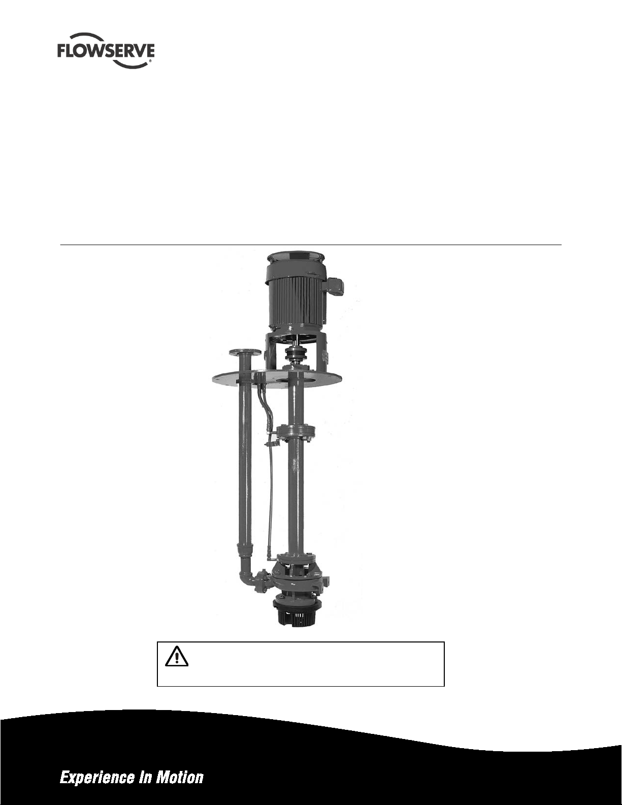
ESP2 Vertical Immersion Sump Pump
Installation
USER INSTRUCTIONS
Operation
HOC3 Hydraulics
PCN=71569292 – 4-12 (E)
Original Instructions
Maintenance
These instructions must be read prior to installing,
operating, using and maintaining this equipment.
Page 2

ESP2 USER INSTRUCTIONS ENGLISH PCN-(71569292) 4-12
CONTENTS
Page
1 INTRODUCTION AND SAFETY ........................... 3
1.1 General ........................................................... 3
1.2 CE marking and approvals .............................. 3
1.3 Disclaimer ....................................................... 3
1.4 Copyright ......................................................... 3
1.5 Duty conditions................................................ 3
1.6 Safety .............................................................. 4
1.7 Name plate and safety labels .......................... 7
1.8 Noise level ....................................................... 8
2 TRANSPORT AND STORAGE ............................. 9
2.1 Consignment receipt and unpacking............... 9
2.2 Handling .......................................................... 9
2.3 Lifting ............................................................... 9
2.4 Storage .......................................................... 10
2.5 Recycling and end of product life .................. 10
3 DESCRIPTION .................................................... 10
3.1 Configurations ............................................... 10
3.2 Nomenclature ................................................ 11
3.3 Design of major parts .................................... 11
3.4 Performance and operation limits ................. 11
4 INSTALLATION ................................................... 15
INSTALLA TION AND START-UP CHECKLIST .... 15
4.1 Location ......................................................... 16
4.2 Part assemblies............................................. 16
4.3 Foundation .................................................... 16
4.4 Pump Mounting ............................................. 16
4.5 Driver Mounting ............................................. 16
4.6 Piping ............................................................ 17
4.7 Electrical connections ................................... 19
4.8 Level controls ................................................ 19
APEX SWITCH .................................................... 26
4.9 Protection systems ........................................ 27
6.6 Setting impeller clearance and impeller
replacement .................................................. 38
6.7 Disassembly ................................................. 38
6.8 Examination of parts ..................................... 40
6.9 Assembly of pump and seal .......................... 42
7 FAULTS; CAUSES AND REMEDI ES ................. 45
8 PARTS LIST AND DRAWINGS .......................... 47
General arrangement drawing ............................. 59
9 CERTIFICATION ................................................. 59
10 OTHER RELEVANT DOCUMENTATION AND
MANUALS .......................................................... 59
10.1 Supplementary User Instructions ............... 59
10.2 Change notes ............................................. 59
10.3 Additional sources of information................ 59
5 COMMISSIONING, STARTUP, OPERATION AND
SHUTDOWN ...................................................... 27
5.1 Pre-commissioning procedure ...................... 27
5.2 Bearing Lubrication ....................................... 29
5.3 Setting the Impeller Clearance ...................... 31
5.4 Direction of rotation ....................................... 32
5.5 Guarding ....................................................... 32
5.6 Priming and auxiliary supplies ....................... 32
5.7 Starting the pump .......................................... 32
5.8 Running or operation .................................... 33
5.9 Stopping and shutdown ................................. 34
5.10 Hydraulic, mechanical and electrical duty ... 34
6 MAINTENANCE ................................................... 35
6.1 Maintenance schedule .................................. 35
6.2 Spare parts .................................................... 36
6.3 Recommended spares and consumable items
....................................................................... 36
6.4 Tools required ................................................ 37
6.5 Fastener torques ........................................... 38
Page 2 of 64
Page 3

ESP2 USER INSTRUCTIONS ENGLISH PCN-(71569292) 4-12
1 INTRODUCTION AND SAFETY
1.1 General
These instructions must always be kept
close to the product's operating location o r
directly with the product.
Flowserve products are designed, developed and
manufactured with state-of-the-art technologies in
modern facilities. The unit is produced with great
care and commitment to continuous quality control,
utilizing sophisticated quality techniques, and safety
requirements.
Flowserve is committed to continuous quality
improvement and being at your service for any further
information about the product in its installation and
operation or about its support products, repair and
diagnostic services.
These instructions are intended to facilitate
familiarization with the product and its permitted use.
Operating the product in compliance with these
instructions is important to help ensure reliability in
service and avoid risks. The instructions may not
take into account local regulations; ensure such
regulations are observed by all, including those
installing the product. Always coordinate repair
activity with operations personnel, and follow all plant
safety requirements and applicable safety and health
laws/regulations.
These instructions must be read prior to
installing, operating, using and maintaining the
equipment in any region worldwide. The
equipment must not be put into service u n til all
the conditions relating to safety noted in the
instructions, have been met.
1.2 CE marking and approvals
It is a legal requirement that machinery and equipment
put into service withi n certai n regi ons of the worl d shall
conform with the applicable CE Marking Directives
covering Machinery and, w he re a ppli c able , Low V ol ta ge
Equipment, Electromagnetic Compatibility (EMC),
Pressure Equipment Directive (PED) and Equipment for
Potentially Explosive Atmospheres (ATEX).
Where applicable, the Directiv es and any additi onal
Approvals, cover important safety aspects relating to
machinery and equipment and the satisfactory provision
of technical documents and safety instructions. Where
applicable this document incorporates information
relevant to t he se Di re ctive s a nd App rov al s.
To confirm the Approval s a pply ing an d i f th e p rodu c t i s
CE marked, check the serial number plate markings
and the Certification. (See section 9, Certification.)
1.3 Disclaimer
Information in these User Instructions is believed
to be reliable. In spite of all the efforts of
Flowserve Pump Division to provide sound and all
necessary information the content of this manual
may appear insufficient and is not guaranteed by
Flowserve as to its completeness or accuracy.
Flowserve manufactures products to exacting
International Quality Management System Standards
as certified and audited by external Quality
Assurance organizations. Genuine parts and
accessories have been designed, tested and
incorporated into the products to help ensure their
continued product quality and performance in use.
As Flowserve cannot test parts and accessories
sourced from other vendors the incorrect
incorporation of such parts and accessories may
adversely affect the performance and safety features
of the products. The failure to properly select, inst a ll
or use authorized Flowserve parts and accessories is
considered to be misuse. Damage or failure caused
by misuse is not covered by the Flowserve warranty.
In addition, any modification of Flowserve products or
removal of original components may impair the safety
of these products in their use.
1.4 Copyright
All rights reserved. No part of these instructions may
be reproduced, stored in a retrieval system or
transmitted in any form or by any means without prior
permission of Flowserve Pump Division.
1.5 Duty conditions
This product has been selected to meet the
specifications of your purchaser order. The
acknowledgement of these conditions has been sent
separately to the Purchaser. A copy should be kept
with these instructions.
The product must not be operated beyond
the parameters specified for the application. If
there is any doubt as to the suitability of the
product for the application intende d , contact
Flowserve for advice, quoting the serial number.
If the conditions of service on your purchase order are
going to be changed (for ex ample liquid pu mped,
temperature or duty) it is requested that the user seeks
the written agreement of Flowserve before start up.
Page 3 of 64
Page 4

ESP2 USER INSTRUCTIONS ENGLISH PCN-(71569292) 4-12
1.6 Safety
1.6.1 Summary of safety markings
These User Instructions contain specific safety
markings where non-observance of an instruction would
cause hazards. The specific safety markings are:
This symbol indicates electrical safety
instructions where non-compliance will invo lve a high
risk to personal safety or the loss of life.
This symbol indicates safety instructio ns where
non-compliance would affect persona l saf et y and
could result in loss of life.
This symbol indicates “hazardous and toxic fluid”
safety instructions where non-compliance would affect
personal safety and could result in loss of life.
This symbol indicates safety
instructions where non-compliance will involve some
risk to safe operation and personal safety and would
damage the equipment or property.
This symbol indicates explosive atmosphere
zone marking according to ATEX. It is used in safety
instructions where non-compliance in the hazardo us
area would cause the risk of an explosion.
This symbol is used in safety instructions to
remind not to rub non-metallic surfaces with a dry
cloth; ensure the cloth is damp. It is used in safety
instructions where non-compliance in the hazardo us
area would cause the risk of an explosion.
This sign is not a safety symbol but indicates
an important instruction in the assembly process.
1.6.2 Personnel qualification and training
All personnel involved in the operation, installation,
inspection and maintenance of the unit must be
qualified to carry out the work involved. If the
personnel in question do not already possess the
necessary knowledge and skill, appropriate training
and instruction must be provided. If required the
operator may commission the manufacturer/supplier
to provide applicable training.
Always coordinate repair activity with operatio ns and
health and safety personnel, and follow all plant
safety requirements and applicable safety and health
laws and regulations.
1.6.3 Safety action
This is a summary of conditions and actions to
help prevent injury to personnel an d d amage to
the environment and to equipment. For products
used in potentially explosive atmospheres
section 1.6.4 also applies.
NEVER DO MAINTENANCE WORK
WHEN THE UNIT IS CONNECTED TO POWER
(Lock out.)
DRAIN THE PUMP AND ISOLATE PIPEWORK
BEFORE DISMANTLING THE PUMP
The appropriate safety precautions should be taken
where the pumped liquids are hazardous.
FLUOROELASTOMERS (When fitted.)
When a pump has experienced temperatures over
250 ºC (482 ºF), partial decomposition of
fluoroelastomers (example: Viton) will occur. In this
condition these are extremely dangerous and skin
contact must be avoided.
HANDLING COMPONENTS
Many precision parts have sharp corners and the
wearing of appropriate safety gloves and equipment
is required when handling these components. To lift
heavy pieces above 25 kg (55 lb) use a crane
appropriate for the mass and in accordance with
current local regulations.
NEVER OPERATE THE PUMP WITHOUT THE
COUPLING GUARD AND ALL OTHER SAFETY
DEVICES CORRECTLY INSTALLED
GUARDS MUST NOT BE REMOVED WHILE
THE PUMP IS OPERATIONAL
THERMAL SHOCK
Rapid changes in the temperature of the liquid within
the pump can cause thermal shock, which can result
in damage or breakage of components and should be
avoided.
NEVER APPLY HEAT TO REMOVE IMPEL L E R
Trapped lubricant or vapor could cause an explosion.
HOT (and cold) PARTS
If hot or freezing co mponents o r auxilia ry heating
equipment can present a danger to operators and
persons entering the immediate area, action must be
taken to avoid acciden tal conta ct (such a s shieldi ng).
Page 4 of 64
Page 5

ESP2 USER INSTRUCTIONS ENGLISH PCN-(71569292) 4-12
If complete prote ction is not possibl e, the machi ne
access must be limited to maintenance staff only with
clear visual w arni ng s a nd indi cato r s t o tho se e nte ring
the immediate area. Note: bearing housings must not
be insulated and drive motors and bearings may be hot.
If the temperature is greater than 68 °C (175 °F) or
below 5 °C (20 °F) in a restricted zone, or exceeds
local regulations, action as above shall be taken.
HAZARDOUS LIQUIDS
When the pump is handling hazardous liquids care
must be taken to avoid exposure to the liquid by
appropriate pump placement, limiting personnel
access and by operator training. If the liqu id is
flammable and/or explosive, strict safety procedures
must be applied.
Gland packing must not be used when pu mping
hazardous liquids.
PREVENT EXCESSIVE EXTERNAL
PIPE LOAD
Do not use pump as a support for piping. Do not
mount expansion joints, unless allowed by Flowserve
in writing, so that their force, due to internal pressure,
acts on the pump flange.
THE PUMP SHAFT MUST TURN
CLOCKWISE WHEN VIEWED FROM THE MOTOR
END
It is absolutely essential that the rotation of the motor
be checked before installation of the coupling spacer
and starting the pump. Incorrect rotation of the pump
for even a short period can unscrew the impell er,
which can cause significant damage.
1.6.4 Products used in potentially explosive atmospheres
Measures are required to:
• Avoid excess temperature
• Prevent buildup of explosive mixtures
• Prevent the generation of spark s
• Prevent leakages
• Maintain the pump to avoid hazard
The following instructions for pumps and pump units
when installed in potentially explosive atmospheres
must be followed to help ensure explosion protection.
Both electrical and non-electrical equipment must meet
the requirement s o f E ur ope an Dir e ctiv e 9 4/9/E C.
1.6.4.1 Scope of compliance
ENSURE CORRECT LUBRICA TION
(See section 5, Commissioning, startup, operation
and shutdown.)
NEVER EXCEED THE MAXIMUM
DESIGN PRESSURE (MDP) AT THE
TEMPERATURE SHOWN ON THE PUMP
NAMEPLATE
See section 3 for pressure versus temperature
ratings based on the material of construction.
NEVER OPERATE THE PUMP WITH
THE DISCHARGE VALVE CLOSED
(Unless otherwise instructed at a specific point in the
User Instructions.)
(See section 5, Commissioning start-up, operation
and shutdown.)
NEVER RUN THE PUMP DRY OR
WITHOUT PROPER PRIME (Casing flooded)
NEVER OPERATE THE PUMP AT
ZERO FLOW OR FOR EXTENDED PERIODS
BELOW THE MINIMUM CONTINUOUS FLOW
Use equipment only in the zone for which it is
appropriate. Always check that the driver, drive
coupling assembly, seal and pump equipment are
suitably rated and/or certified for the classification of
the specific atmosphere in which they are to be
installed.
Where Flowserve has supplied only the bare shaft
pump, the Ex rating applies only to the pump. The
party responsible for assembling the pump set shall
select the coupling, driver, seal and any additional
equipment, with the necessary CE Certificate/
Declaration of Conformity establishing it is suitable for
the area in which it is to be installed.
The output from a variable frequency drive (VFD) can
cause additional heating affects in the motor. On
pump installations controlled by a VFD, the ATEX
Certification for the motor must state that it covers the
situation where electrical supply is from the VFD.
This particular requirement still applies even if the
VFD is in a safe area.
Page 5 of 64
Page 6

Temperature
Maximum
permitted
Temperature limit of liquid
variant – check which is lower)
Temperature
T1
450 °C (842 °F)
350 °C (662 °F) *
ESP2 USER INSTRUCTIONS ENGLISH PCN-(71569292) 4-12
1.6.4.2 Marking
An example of ATEX equipment marking is shown
below. The actual classification of the pump will be
engraved on the nameplate.
II 2 GD c IIC 135ºC (T4)
Equipment Group
I = Mining
II = Non-mining
Category
2 or M2 = High level protection
3 = normal level of protection
Gas and/or dust
G = Gas
D= Dust
c = Constructional safety
(in accordance with En13463-5)
Gas Group (Equipment Category 2 only)
IIA – Propane (Typical)
IIB – Ethylene ( T y pi cal)
IIC – Hydrog en (Typical)
Maximum surface temperature (Temperature Class)
(see section 1.6.4.3)
1.6.4.3 Avoiding excessive surface temperatures
ENSURE THE EQUIPMENT TEMPERATURE
CLASS IS SUITABLE FOR THE HAZARD ZONE
Pump liquid temperature
Pumps have a temperature class as stated in the ATEX
Ex rating on the nameplate . These are ba sed on a
maximum ambient temperature of 40 ºC (104 ºF); refer
to Flowserve for higher ambient temperatures.
The surface temperature on the pump is influenced by
the temperature of the liquid handled. The maximum
permissible liquid te mperature depends on the
temperature class and must not exceed the values in the
table applicable below. The temperature rise a t the seal s
and bearings and due to th e minimum pe rmitted flow rate
is taken into account in the temperatures stated.
Maximum permitted liquid temperature for pumps
class to
EN 13463-1
T6
T5
T4
T3
T2
T1
surface
temperature
85 °C (185 °F)
100 °C (212 °F)
135 °C (275 °F)
200 °C (392 °F)
300 °C (572 °F)
450 °C (842 °F)
handled (* depending on
material and construction
Consult Flowserve
Consult Flowserve
115 °C (239 °F) *
180 °C (356 °F) *
275 °C (527 °F) *
400 °C (752 °F) *
Maximum permitted liquid temperature fo r pumps
with self-priming casing
Temperature limit of liquid
handled (* depending on
material and construction
variant - check which is lower)
Consult Flowserve
Consult Flowserve
110 °C (230 °F) *
175 °C (347 °F) *
270 °C (518 °F) *
class to
EN 13463-1
T6
T5
T4
T3
T2
Maximum
surface
temperature
permitted
85 °C (185 °F)
100 °C (212 °F)
135 °C (275 °F)
200 °C (392 °F)
300 °C (572 °F)
The responsibility for compliance with the specified
maximum liquid temperature is with the plant
operator.
Temperature classification “Tx” is used when the
liquid temperature varies and the pump could be
installed in different hazardous atmospheres. In this
case the user is responsible for ensuring that the
pump surface temperature does not exceed that
permitted in the particular hazardous atmosphere.
Do not attempt to check the dir ection of rotat ion with the
coupling element/pins fitted due to the risk of severe
contact between rot ating and stationa ry compon ents.
Where there is any risk of the pump being run against a
closed valve generatin g high liqu id and ca sing exte rnal
surface temperature, it is recommended that users fit an
external surface temperature protection device.
Avoid mechan i cal , hy d raul ic o r electrical overload by
using motor overload trips, temperature monitor or a
power monitor and perform routine vibration monitoring.
In dirty or dusty environments, regular checks must
be made and dirt removed from areas around close
clearances, bearing housings and motors.
1.6.4.4 Preventing the buildup of explosive mixtures
ENSURE PUMP IS PROPERLY FILLED AND
VENTED AND DOES NOT RUN DRY
Ensure that the pump and relevant suction and discharge
piping is totally filled with li quid at all ti mes du ring the
pumps operation so tha t an expl osive at mosphere is
prevented. In addition, i t is essential to make sure that
seal chambers, auxiliary shaft seal systems and any
heating and cooling systems are properly filled.
Page 6 of 64
Page 7
ESP2 USER INSTRUCTIONS ENGLISH PCN-(71569292) 4-12
If the operation of the system can not avoid this
condition it is recommended that you fit an
appropriate dry run protection device (for example
liquid detection or a power monitor).
To avoid potential hazards from fugitive emissions of
vapor or gas to atmosphere, the surrounding area
must be well ventilated.
1.6.4.5 Preventing sparks
To prevent a potential hazard from mechanical
contact, the coupling guard must be non-sparking for
Category 2.
To avoid the potential hazard from random induced
current generating a spark, the baseplate must be
properly grounded.
Avoid electrostatic charge. Do not rub nonmetallic surfaces with a dry cloth; ensure the cloth is
damp.
The coupling must be selected to comply with
94/9/EC and correct alignment must be maintained.
Additional requirements for pumps on nonmetallic baseplates
When metallic components are fitted on a nonmetallic baseplate they must be individually earthed.
1.6.4.6 Preventing leakage
Avoid entrapment o f l iqui d in the pump and
associated piping due to closing of suction and
discharge valves, which could cause dangerous
excessive pressures to occur if there is heat input to the
liquid. This can occur if the pump is stationary or
running.
Bursting of liquid containing parts due to freezing
must be avoided by draining or protecting the pump
and auxiliary systems.
Where there is the potenti al hazard of a lo ss of a seal
barrier fluid or external flush, the fluid must be monitored.
If leakage of liquid to atmosphere can result in a
hazard, the installation of a liquid detection device is
recommended.
1.6.4.7 Maintenance of the centrifugal pump to avoid a hazard
CORRECT MAINTENANCE IS REQUIRED TO
AVOID POTENTIAL HAZARDS WHICH GIVE A
RISK OF EXPLOSION
The responsibility for compliance with maintenance
instructions is with the plant operator.
To avoid potential explosion hazards during maintenance,
the tools, cleaning and painting materials used must not
give rise to sparking o r adversely affect the ambient
conditions. Where there is a risk from such tools or
materials, maintenance must be conducted in a safe area.
It is recommended that a maintenance plan and schedule
is adopted. (See section 6, Maintenance.)
1.7 Name plate and safety labels
1.7.1 Nameplate
For details of nameplate, see the Declaration of
Conformity and section 3.
1.7.2 Safety labels
J218JZ250
ESSENTIAL PROCEEDURES BEFORE STARTING:
INSTALL AND OPERATE EQUIPM ENT IN
ACCORDAND WITH THE INSTRUCTION
MANUAL SUPPLIED SEPARATELY.
ENSURE GUARDS ARE SECURELY IN
PLACE.
ENSURE CORRECT DIRECTION OF
ROTATION.
ENSURE CORRECT DRIVER DIRECTION
OR ROTATION WIT H COUPLING
ELEMENT / PINS REMOVED: OTHERWISE
SERIOUS DAMAGE MAY RESULT .
VERIFIER LE SENS CORRECT DE
ROTATION DU MOTEUR. POMPE
DESACCOUPLEE / ENTRETOISE
DEMONTEE. NE PAS SUIVRE CETTE
RECOMMANDATION PEUT CONDUIRE A
DE GRAVES DOMMAGES POUR LA POMPE
CDC: 603 604 610 612 62 1 62 3 624
ENSURE ALL EXTERNAL CONNECTIONS TO
THE PUMP / SHAFT SEALING AND DRIVER
ARE CONNECTED AND OPERATIONAL
FULLY PRIME UNIT AND SYSTEM.
DO NOT RUN UNIT DRY
FAILURE TO FOLLOW THESE PROCEEDURES
MAY RESULT IN PERSONAL INJURY
AND/ OR EQUIPMENT DAMAGE
J218JZ250
KONTROLLE VORGESCHRIEBENER
DREHRICHTUNG ! HIERZU
KUPPLUNGSZWISCHENSTÜCK /
KUPPLUNGSBOLZEN ENTFERNEN.
ANDERENFALLS ERNSTHAFTE SCHÄDEN !
ZORG VOOR JUISTE ROT ATIER ICHTING
VAN DRIJFAS WAARBIJ DE
KOPPELELELMENTEN / PENNEN
VERWIJDERD ZIJN: VERZUM KAN
ERNSTIGE SCHADE TOT GEVOLG HABBEN.
Page 7 of 64
Page 8

ESP2 USER INSTRUCTIONS ENGLISH PCN-(71569292) 4-12
1.8 Noise level
When pump noise level exceeds 85 dB(A) attention
must be given to prevailing Health and Safety
Legislation, to limit the exposure of pla nt operat in g
personnel to the noise. The usual approach is to
control exposure time to the noise or to enclose the
machine to reduce emitted sound. You may have
already specified a limiting noise le ve l when the
equipment was ordered, however if no noise
requirements were defined then m ac hines abo ve a
certain power level will exceed 85 dB(A). In such
situations consideration must be given to the fitting of
an acoustic enclosure to meet local regulations.
Pump noise level is dependen t on a numbe r of factors -
The values are based on the noisiest non-geared
electric motors that are likely to be encountered.
They represent sound pressure levels at 1 m (3.3 ft)
from the directly driven pump, for "free field over a
reflecting plane". For estimating L
sound power
wA
level (re 1 pW) add 14dBA to the sound pressure
value.
If a pump unit only has been purchased, for fitting
with your own driver, then the "pump only" noise
levels from the table should be combined with the
level for the driver obtained from the supplier.
If the motor is driven by an inverter it may show an
increase in noise level at some speeds. Consult a
Noise Specialist for the combined calculation.
the type of motor fitted, the ope rating capa city, pipework
design and acoustic characteristics of the building.
Typical sound pressure levels measured in dB, and
A-weighted are shown in the table below. The figures
are indicative only, they are subject to a +3 dB
For units driven by equipment other than
electric motors or units contained within enclosures,
see the accompanying information sheets and
manuals.
tolerance, and cannot be guaranteed.
Ty pical sound pressure level, dBA, L
Motor size
and speed
kW (hp)
<0.55 (<0.75)
0.75 (1)
1.1 (1.5)
1.5 (2)
2.2 (3)
3 (4)
4 (5)
5.5 (7.5)
7.5 (10)
11 (15)
15 (20)
18.5 (25)
22 (30)
30 (40)
37 (50)
45 (60)
55 (75)
75 (100)
90 (120)
110 (150)
150 (200)
200 (270) (1) (1) (1) (1) (1) 83 (1) 80
300 (400) - - - - (1) 84 (1) 81
(1) Motors in this range are generally job specific and noise levels should be calculated based on actual equipment installed.
For 960 r/min reduce 1450 r/min values by 5 dBA.
3550 r/min 2900 r/min 1750 r/min 1450 r/min
Pump and
motor
dBA
71 66 64 62 64 62 63 62
74 66 67 62 67 62 63 62
74 68 67 64 67 64 65 64
77 70 70 66 70 66 66 66
78 72 71 68 71 68 68 68
81 74 74 70 74 70 70 70
82 75 75 71 75 71 71 71
90 77 83 73 76 73 72 71
90 78 83 74 77 74 73 72
91 80 84 76 78 76 74 73
92 83 85 79 80 79 76 75
92 83 85 79 80 79 76 75
92 83 85 79 81 79 77 75
100 85 93 81 84 80 80 76
100 86 93 82 84 80 80 76
100 87 93 83 84 80 80 76
100 88 95 84 86 81 82 77
100 90 95 86 88 81 83 78
100 90 95 86 90 81 85 78
100 91 95 87 91 83 86 79
101 92 96 88 91 83 86 79
Pump
only
dBA
at 1 m reference 20 μPa
pA
Pump and
motor
dBA
Pump
only
dBA
Pump and
motor
dBA
Pump
only
dBA
Pump and
motor
dBA
Pump
only
dBA
Page 8 of 64
Page 9

ESP2 USER INSTRUCTIONS ENGLISH PCN-(71569292) 4-12
ESP2
Base Pump
Kg (lb) per 0.15m
Pump Size
Wt. Kg (lb)
Extra Length
Group 1
1.5x1x6
136 (300)
3.6 (8)
3x1.5x6
139 (305)
3.6 (8)
3x2x6K
145 (320)
4.1 (9)
1.5x1x8
148 (325)
3.6 (8)
3x1.5x8
150 (330)
3.6 (8)
Group 2
3x2x8
184 (405)
7.3 (16)
4x3x8
223 (490)
7.7 (17)
4x3x8L
223 (490)
7.7 (17)
2x1x10
182 (400)
6.8 (15)
3x1.5x10
223 (490)
6.8 (15)
3x2x10
232 (510)
7.3 (16)
4x3x10L
309 (680)
7.7 (17)
6x4x10
323 (710)
8.6 (19)
3x1.5x13
3x2x13
264 (580)
7.3 (16)
4x3x13
302 (665)
7.7 (17)
Group 3
6x4x13
407 (895)
11.4 (25)
8x6x13
545 (1200)
15 (33)
8x6x15
561 (1235)
15 (33)
10x8x15
645 (1420)
2 TRANSPORT AND STORAGE
2.1 Consignment receipt and unpacking
Immediately after receipt of the equipment it must be
checked against the delivery/s hipping documents for
its completeness and that there has been no
damage in transportation. Any shortage and/or
damage must be reported immediately to Flowserve
Pump Division and must be received in writing within
ten days of receipt of the equipment. Later claims
cannot be accepted.
Check any crate, boxes or wrappings for any
accessories or spare parts that may be packed
separately with the equipment or attached to pallet,
box, or equipment.
Each product has a unique serial number. Check
that this number corresponds with the order. Always
quote this number in correspondence as well as
when ordering spare parts or further accessories.
2.2 Handling
Boxes, crates, pallets or cartons may be unloaded
using fork lift vehicles or slings dependent on their
size and construction. The unit should be stored in a
level position with no strains applied.
2.3 Lifting
Pump Weights
3x2x8
3x1.5x8
4x3x10
152 (335)
182 (400)
286 (630)
259 (570)
(6 in.)
4.1 (9)
6.8 (15)
7.7 (17)
6.8 (15)
Pumps and motors often have
integral lifting lugs or eye bolts. These are intended
for use in only lifting the individual piece of
equipment.
Do not use eye bolts or cast-in lifting
lugs to lift pump, motor and baseplate assemblies.
Care must be taken to lift components
or assemblies above the center of gravity to prevent
the unit from flipping. This is especially true with
In-Line pumps.
Carefully sling ESP pumps so that
bearing lubrication lines (3840.1) will not be bent or
damaged when lifting.
It is advisable to raise the pump into the vertical
position before uncrating. If this isn't possible, pumps
over eight feet long must be supported at more than
one place when raising to the vertical position. Use a
support strap around the bottom column (1341.2)
and on the motor support (3160).
10x8x13 616 (1355)
16.4 (36)
16.4 (36)
Base pump lengths are 0.61m (2 ft.) for
Group 1 & Group 2 pumps and 0.91m (3 ft.) for Group
3 pumps.
On pumps equipped with grease lubricated
shaft bearings, (3020.1 and 3020.2) take care not to
flush the grease from the bearings.
Page 9 of 64
Page 10
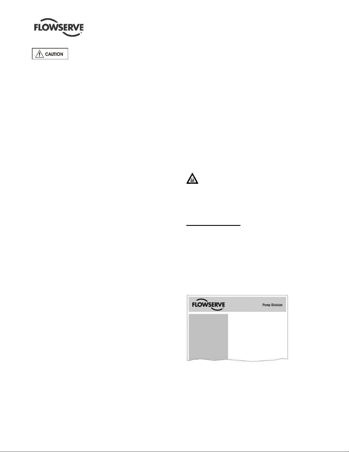
Figure 3-1: Nameplate mounted to housing
Serial No.
2.4 Storage
Store the pump in a clean, dry
location away from vibration. Leave flange covers in
place to keep dirt and other foreign material out of
pump casing.
The pump may be stored as above for up to 6
months. Consult Flowserve for preservative actions
when a longer storage period is needed.
2.4.1 Short term storage and packaging
Normal packaging is designed to protect the pump
and parts during shipment and for dry, indoor
storage for up to six months or less. The following is
an overview of our normal packaging:
• All loose unmounted items are pack aged in a
water proof plastic bag or box.
• Inner surfaces of the bearing housing, shaft (area
through bearing ho u sing) and be a rings a re coat ed
with Cortec VCI-329 rust inhibitor, or equal.
• Regreaseable bearings in the pump are packed
with Keystone 81-EP-2 lithium-based grease for
the thrust bearing (and the line shaft bearings
when grease lubrication is used).
• The internal surfaces of ferrous casings, covers,
flange faces, and the impeller surface are
sprayed with Cortec VCI-389, or equal
• Exposed shafts are taped with Polywrap
• Flange covers are secured to both the suction
and discharge flanges
• In some cases with assemblies ordered with
external piping, components may be
disassembled for shipment
• The pump must be stored in a covered, dry
location
• Every three months the pump shaft should be
rotated several revolutions to prevent brinelling
of the thrust bearing and sticking of the seal
faces (if fit t ed).
2.4.2 Long term storage and packagin g
Long term storage is defined as more than six
months, but less than 12 months. The procedure
Flowserve follows for long term storage of pumps is
given below. These procedures are in addition to
the short term procedure.
• Each assembly is hermetically (heat) sealed
from the atmosphere by means of tack wrap
sheeting and rubber bushings (mounting holes)
• Desiccant bags are placed inside the tack
wrapped packaging
• A solid wood box is used to cover the assembly
ESP2 USER INSTRUCTIONS ENGLISH PCN-(71569292) 4-12
This packaging will provide protection for up to
twelve months from humidity, salt laden air, dust etc.
After unpacking, protection will be the responsibility of
the user. Addition of oil to the bearing housing will
remove the inhi bit or . If uni t s a re to be idle for extended
periods after addition of lubricants, inhibitor oils and
greases should be used.
2.5 Recycling and end of product life
At the end of the service life of the product or its
parts, the relevant materials and parts should be
recycled or disposed of using an environmentally
acceptable method and in accor danc e with loca l
regulations. If the product contains substances that
are harmful to the environment, these should be
removed and disposed of in accordance with current
local regulations. This also includes the liquids
and/or gases that may be used in the "seal system"
or other utilities.
Make sure that hazardous substances are
disposed of safely and that the correct personal
protective equipment is used. The safety
specifications must be in accordance with the current
local regulations at all times.
3 DESCRIPTION
3.1 Configurations
The ESP2 vertical imm ersion sump pumps are
separately coupled, metallic construction, single
stage, centrifugal pumps for wet pit applications.
The ESP2 wetted parts are available in a wide rang e
of materials to handle most fluids. Vapor tight, vapor
proof, and pressurized options are available.
Equipment No.
Purchase Order
Model
Size
MDP
Material
Date DD/MMM/YY
ESP2
6X4X10
Page 10 of 64
Page 11

ESP2 USER INSTRUCTIONS ENGLISH PCN-(71569292) 4-12
MCF % of BEP
r/min
r/min
r/min
Group 1
1.5x1x6
10
10
10
3x1.5x6
10
10
10
3x2x6K
10
10
10
1.5x1x8
10
10
10
3x1.5x8
n.a.
10
10
3x2x8
n.a.
10
10
Group 2
3x1.5x8
10
10
10
3x2x8
10
10
10
4x3x8
25
10
10
4x3x8L
n.a.
25
10
2x1x10
n.a.
25
10
3x1.5x10
n.a.
25
10
3x2x10
n.a.
25
10
4x3x10
n.a.
25
10
4x3x10L
n.a.
25
10
6x4x10
n.a.
25
10
3x1.5x13
n.a.
25
10
3x2x13
n.a.
25
10
4x3x13
n.a.
25
10
Group 3
6x4x13
n.a.
25
10
8x6x13
n.a.
25
10
10x8x13
n.a.
25
10
8x6x15
n.a.
n.a.
25
10x8x15
n.a.
n.a.
25
3.2 Nomenclature
The pump size will be engraved on the nameplate
typically as below:
6 X 4 X 10
• “6” = nominal suction port size (in.)
• “4” = Nominal discharge port size (in.)
• Nominal maximum impelle r diamete r. “10” = 10 in.
• Actual impeller size
“9.5” = 9 ½ in. diameter; “8.13” = 8 ⅛ in;
”7.75” = 7 ¾ in
3.3 Design of major parts
3.3.1 Pump casing
Casings are either a single or double volute design with
a centerline discharge.
3.3.2 Impeller
The impeller is an open design and is threaded to the
end of the shaft.
3.3.3 Shaft
Solid shafting is supported on plain bear ings with a
thrust bearing located above the sump level.
3.3.4 Pump bearings and lubrication
Grease lubricated double row angular contact ball
bearings are fitted as standard for the external thrust
bearings. The plain bearings that support the shaft
against radial loads can be lubricated either by
external flush, product, or grease (see Fig. 3-4).
3.3.5 Bearing housing
The external bearing housing holds the thrust
bearing and has lip seals to prevent ingress of
contaminates to the bearing grease.
3.3.6 Shaft seal
There is no shaft seal required near the impeller
since the pump is submerged. Only a small amount
of pressurized fluid escapes through controlled leak
paths from the backside of the impeller. Packing or
a mechanical seal can be fitted above the sump level
to provide vapor proof or pressurized options for the
application.
3.3.7 Driver
The driver is normally a vertical electric motor.
3.3.8 Accessories
Accessories may be fitted when specified by the
customer.
3.4 Performance and operation limits
This product has been selected to meet the
specification of your purchase order. See se cti on 1. 5.
The following data is included as additional information
to help with y our in stal l ati on . I t i s ty pi cal, a nd facto r s
such as liquid being pumped, temperature, material of
construction, an d se al ty pe may i n fluen ce this data. If
required, a definitive statement for your application can
be obtained from Flowse rve.
3.4.1 Minimum continuous flow
The minimum continuous flow (MCF) is based on a
percentage of the best efficiency point (BEP). Figure
3-2 identifies the MCF for all ESP pump models.
FIGURE 3-2: Minimum continuous flow
Pump size
3500/2900
1750/1450
1180/960
Page 11 of 64
Page 12

ESP2 USER INSTRUCTIONS ENGLISH PCN-(71569292) 4-12
Suct.
Flow
(m3/hr.)
Size
6.8
11.4
20.5
45.5
79.5
136
273
341
500
568
727
1023
1250
1.5 in
0.30
0.55
1.07
2.65 2 in
0.30
0.58
1.40
2.74
3 in
0.30
0.79
1.52
2.38 4 in 0.30
0.55
1.07
2.13
6 in 0.43
0.76
1.19
1.83
8 in 0.55
0.94
1.19
1.65
10 in 0.64
0.85
1.22
1.52
Suct.
Flow
(GPM) Size
30
50
90
200
350
600
1200
1500
2200
2500
3200
4500
5500
1.5 in
1.0
1.8
3.5
8.7 2 in
1.0
1.9
4.6
9.0
3 in
1.0
2.6
5.0
7.8 4 in 1.0
1.8
3.5
7.0
6 in 1.4
2.5
3.9
6.0
8 in 1.8
3.1
3.9
5.4
10 in 2.1
2.8
4.0
5.0
3.4.2 Minimum suction pipe submergence
The minimum submergence is shown in Figures 33A and 3-3B below.
FIGURE 3-3A
Minimum submergence (meters)
FIGURE 3-3B
Minimum submergence (feet)
Page 12 of 64
Page 13

Bearing
Material
Max. Product
Pumped Liquid
Lubricant
Shaft
Material
Most clean acids,
External Flush
Steel or SS
BRONZE
82°C
Water and other
External Flush
Steel only
CAST IRON
82°C
Water and other
External Flush
Steel
RUBBER
71°C
General abrasive liquids
External Flush
SS only
TEFLON
177°C
Clean acids not
External Flush
SS only
Grease Lube
Clean acids not
Grease
SS only
VITON
149°C
Dirty acids not
External Flush
SS only
3.4.3 ESP2 Bearing Materials
CARBON - Carbon graphite, especially developed
for sump p ump appl ications , is chem icall y inert.
The self lubricating properties of graphite
present in the carbon bearings enhances its
dry running capabilities.
BRONZE - SAE 660 Bron ze (grooved when
grease lubricated).
CAST IRON - ASTM A48 Class 30 iron (grooved
when grease lubricated).
RUBBER - Resilient compounded rubber, fluted to
allow abrasive s t o wa sh away.
FIGURE 3-4: ESP2 Bearing selection
Temp.
CARBON
177°C
(350°F)
genera! chemical, cold
or hot water, cl eani ng
fluids, gasol ine,
kerosene, jet fuels
ESP2 USER INSTRUCTIONS ENGLISH PCN-(71569292) 4-12
VITON - Resilient Viton, fluted to allow handling of
dirty corrosive liquids not able to be handled by
carbon or rubber.
TEFLON - Fiberglass & moly-disulphide-filled, with
low cold flow, high tensile and elongation characteristics.
All bearing materials are enclosed in an AISI-316
shell (ex. Bronze & Cast Iron). Higher alloys ar e
available (grooved when grease lubricated).
Product Lube
Steel or SS
Liquid Lube
TEFLON 82°C
180°F
(180°F)
(160°F)
(350°F)
(180°F)
(300° F)
compatible liquids
compatible liquids
including alkaline
caustics
compatible w ith rubber
compatible with carbon
compatible with carbon
compatible with carbon
or rubber
Product Lube
Grease
Product Lube
Grease
Product Lube
Product Lube
Product Lube
Steel only
Steel only
Steel
Steel
SS only
SS only
SS only
Page 13 of 64
Page 14

FIGURE 3-5: Engineering information
ESP2 USER INSTRUCTIONS ENGLISH PCN-(71569292) 4-12
Page 14 of 64
Page 15

ESP2 USER INSTRUCTIONS ENGLISH PCN-(71569292) 4-12
4 INSTALLATION INSTAL LAT ION AND S TART-UP
CHECKLIST
1. Check that the sump design will keep the
liquid level within the proper range.
2. Check that the pump location is accessible and
has adequate ventilation.
3. Verify that the pump and motor are suitable for
the pump environment.
4. Check the sump design to be sure it is adequate
to support the complete pumping assembly,
5. Verify the discharge piping meets Hydraulic
Institute Standards for design and is properly
supported.
6. Install the suction strainer
7. Install the liquid level controls.
8. If pump was ordered for vapor proof or
pressurized design, install sealing device.
9. Lift the pump into place, level and tighten the
mounting plate bolts.
10. Install the motor on the pump , but do not connect
the coupling or electric power.
1 _________ __________
2 _________ __________
3 _________ __________
4 _________ __________
5 _________ __________
6 _________ __________
7 _________ __________
8 _________ __________
9 _________ __________
10 _________ __________
11. Connect the wiring to the liquid level
indicators and pump controls, as required.
12. Connect t he di sch arge pip ing ,
13. Check that all auxiliary piping is connected
14. Verify the pump is free of pipe strain by turning
the shaft by hand.
15. Verify the impeller setting.
16. Lubricate the driver, pump thrust and lineshaft
bearings as required using approved lubricants.
17. Connect the wiring for the motor.
18. Turn power ON and jog the driver to verify proper
rotation; clockwise looking down.
19. Turn power OFF and assemble coupling and
install coupling guard. Then turn power ON, but
do not start the driver.
11 _________ __________
12 _________ __________
13 _________ __________
14 _________ __________
15 _________ __________
16 _________ __________
17 _________ __________
18 _________ __________
19 _________ __________
Page 15 of 64
Page 16

ESP2 USER INSTRUCTIONS ENGLISH PCN-(71569292) 4-12
4.1 Location
The pump should be located to allow room for
installation, access, ventilation, maintenance, and
inspection with ample headroom for lifting. Refer to
the general arrangement drawing for the pump set.
If pump is furnished with external flush-lubricated
bearings, the fluid lines must be accessible from
the pump location.
Also important, especially in the larger flow units, is
proper sump design. Liquid velocity approaching
the pump should be one foot per second or less.
When more than one pump is installed and used at
the same time in the same sump, the location and
spacing of the pumps are important. The
guidelines for sump design and pump placement as
outlined in the "Hydraulic Institute Standards" are
recommended.
4.2 Part assemblies
• Pumps are shipped completely assembled
except for driver, strainer (6531), float controls
(if furnished), pit cover, and the mechanical
seal (4200) or packing (4130) for the stuffing
box on a vapor proof or pressurized design
pump.
• When mechanical seals are furnished, they
should be installed before the motor is put in
place. Refer to seal installation instructions in
section 5.1.
• Vapor Proof and Pressurized design pumps
are furnished with an upper stuffing box
(4100). If the stuffing box does not already
have the packing (4130) or seal (4200)
installed, then they should be installed before
the motor is mounted. See section 5.1.
• The driver will be mounted after the pump is
installed.
• When the pump is shipped, all threads and all
openings are covered. This protection should
not be removed until installation. If the pump
is removed from service, this protection should
be reinstalled.
4.3 Foundation
There should be adequate space for workers to
install, operate, and maintain the pump. The
foundation should be sufficient to absorb any
vibration and should provide a rigid support for the
pump and motor. Recommended mass of a
concrete foundation should be three times that of
the pump, motor and mounting plate. Supporting
members must be sufficiently strong to prevent
spring action and/or lateral movement.
4.4 Pump Mounting
The pump may be mounted directly on the pit
using the pum p mountin g plate ( 6110) or in
conjunction with a pit cover.
a) The pump was checked during assembly at
the factory to make sure the pump shaft
(2100) rotated freely by hand. Handling during
shipment, storage, or preparation for
installation could have caused distortions
resulting in pump shaft binding. Check the
shaft to make sure that it will rotate freely by
hand.
b) Check all bolts and nuts for tightness, then
carefully lower the assembled pump into the
pit, taking care not to damage lube lines or float
control equipment. Make sure that any
equipment used to lift the pum p or any of
its components is capable of supporting the
weights encountered. Make su re that all parts
are properly rigged before attempting to lift.
c) Pump mounting plate and/or pit cover mus t
maintain a tolerance of 2.5mm/m (0.03in/ft)
level from one side of the plate to the other,
and be supported evenly at all points before
being bolted down.
d) If the sump doesn't provide a level mounting
surface for the pump, driv e wedges under
the mounting plate/pit cover until pump levels
out. The wedges m ust be able to support the
weight of th e entir e pum ping assembly and
hold the assembly steady enough that no
excess vibration occurs.
e) Do not bolt the discharge flange of the pump
to the piping until the baseplate foundation is
completely installed.
f) Run piping to the discharge of the pump.
There should be no piping loads transmitted to
the pump after connection is made.
4.5 Driver Mounting
a) Before the motor is installed, be sure to
connect the motor half coupling and the pump
half coupling onto their respective shafts.
b) Carefully lift the motor and place it on the
support head (3160) of the pump.
c) Turn the motor frame to one of the four
positions where the motor bolt hol e s li ne up to
the support head (3160). Select the position of
the motor to suit the desired conduit box
location. Install the motor hold down bolts
(6570.1). In some instances a motor adapter may
be furnished. In this case the adapter must be
installed before the motor can be mounted.
Page 16 of 64
Page 17
PLATE
ESP2 USER INSTRUCTIONS ENGLISH PCN-(71569292) 4-12
d) L ocate the coupli ng and source of electri cal
power but DO N OT ASSEMBLE THE
COUPLING AT THIS TIME.
e) Connect the motor terminals to the leads from
the starter panel. Make sure the motor shaft
and/or coupling is not touching any part of the
pump shaft or pump half coupling. Rotate the
motor shaft by hand to make sure it is free to
rotate when energized.
Never check driver rotation unless the
pump and driver are disconnected and
physically separated. Failure to follow this
instruction can result in serio u s damage to the
pump and driver if rotation is in the wrong
direction.
f) Jog the motor and check for proper rotation
which should be clockwise when looking
down on top of the motor. If rotation is wrong,
interchange any two moto r connections on
three-phase motors. On single-phase motors,
follow the motor manufacturer’s instructions. After
changing the connections, again check the rotation
to ensure that the direction is correct.
g) Disconnect and loc kout the power supply to the
driver.
h) The coupling can now be fully installed and
join the driver and pump shafts t ogether (see
section 5.4.2).
i) Install the coupling guarding ( see s ec tion
5.5).
4.6 Piping
4.6.1 Discharge piping
All piping must be ind epe nde ntly supported,
accurately aligned and pre ferably connecte d to the
pump by a short length of flex ible pipi ng. The pu mp
should not hav e to supp o rt th e w eig ht o f the pi pe. It
should be possible to install dis cha rge b ol ts t hrou gh
mating flanges without pulling or prying either of the
flanges. All piping must be tight .
Protective cov er s are fitted to both the
suction and discharge flanges of the casing and must
be removed prior to connecting the pump to any
pipes.
a) Use discharge piping one size larger than the
pump discharge.
b) Discharge piping should be well supported
and connected to the pump such that no strain
or weight of the piping is carried by the pump.
c) Check pump shaft for freedom of rotation by
hand to make sure any discharge piping strain
is not causing binding.
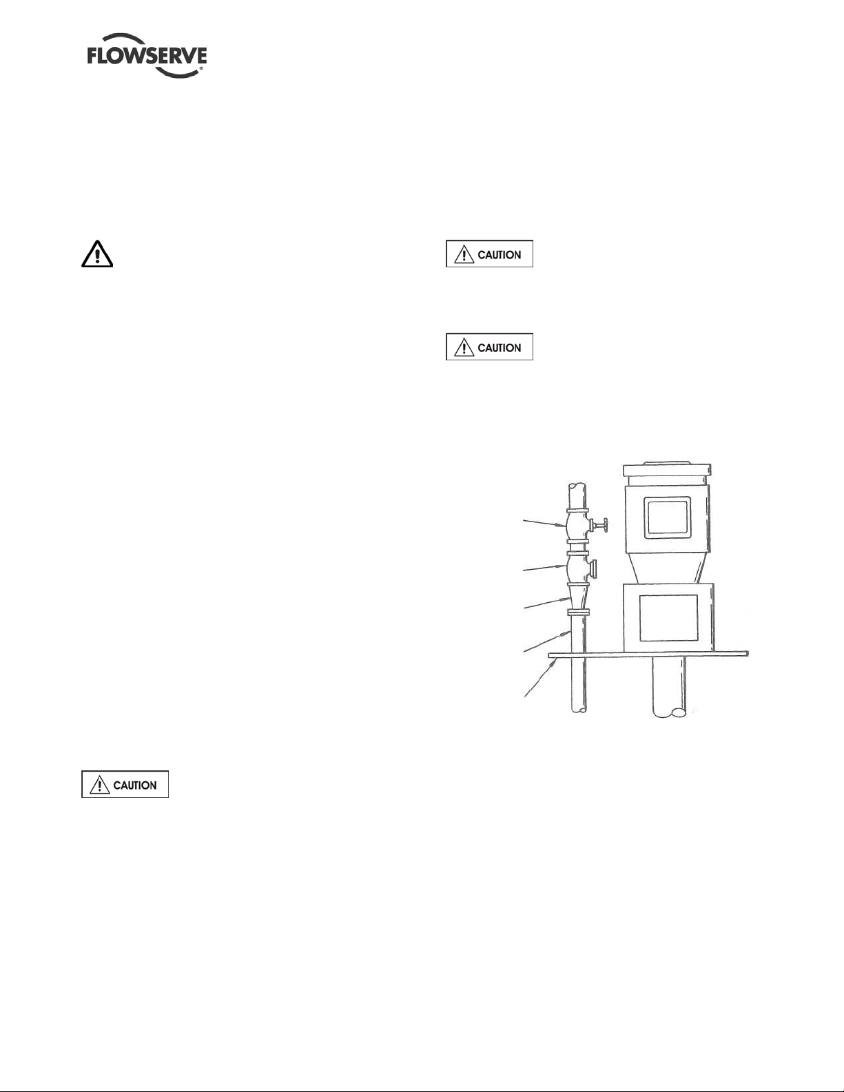
d) After the pump discharge, the increaser
should be the first item in the discharge line,
followed by the check valve and gate valve,
respectively. See Figure 4-1.
e) It is recommended that pressure indicating
devices be installed before and after the
valves in the discharge line to verify the pump
is not being run dry and that the discharge
valves are not closed.
The check valve is required to
prevent back-flow through the pump on shut-down.
This flow could cause the impeller to unscrew from
the shaft and should be avoided.
When fluid velocity in the pipe is
high, for example, 3 m/s (10 ft/sec) or higher, a
rapidly closing discharge valve can cause a
damaging pressure surge. A dampening
arrangement should be provided in the pi pin g.
FIGURE 4-1
GATE
VALVE
CHECK
VALVE
CONCENTRIC
INCREASER
PUMP.
DISCHARGE
MOUNTING,
4.6.2 Suction piping
ESP pumps typic ally only have strainers attached to
the suction flange of the pump casing. An option for
an extension from the suc tion flang e is availab le and
is called a tailpipe ( see sectio n 8 for cross-sectional
drawing). A tailpipe is useful for applications where
there is adequa te NPS H at th e l ow est s ump l ev el but
the discharge pressure is critical and must be
maintained at a maximum value compared to using a
longer column and shaft.
Page 17 of 64
Page 18
ESP2 USER INSTRUCTIONS ENGLISH PCN-(71569292) 4-12
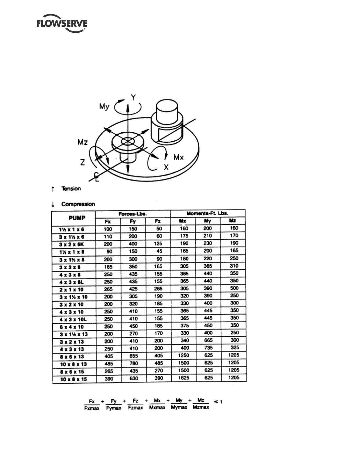
4.6.3 Allowable piping loads
Discharge piping should be constructed to fit to the
ESP discharge piping flange. The ESP design can
accommodate large piping loads without affecting
the operation of the pump, but the installation
FIGURE 4-2 ESP2 nozzle loading
should not impose unnecessary loads to the
discharge flange. The allowable piping loads are
shown in Figure 4.2.
Page 18 of 64
Page 19
ESP2 USER INSTRUCTIONS ENGLISH PCN-(71569292) 4-12
4.6.4 Final pump rotation check
After connecting the piping, rotate the pump drive
shaft clockwise (viewed from motor end) by hand
several complete revolutions to be sure there is no
binding and that all parts are free. If piping caused
unit to be in a bind, correct piping to relieve strain
on the pump.
4.6.5 Auxiliary piping
Check to see if any other connections need to be
made to pump, such as injection water to stuffing
box for seal or packing lubrication (when furnished)
and make the required connections.
4.6.6 Mechanical seal and packing
Pumps supplied with vapor proof construction or
pressurized design are furnished with an upper
stuffing box (4100) equipped to take mechanical
seals or packing (see vapor proof and pressurized
design cross-sections in section 8). Installation
instructions are in section 5.1.
4.7 Electrical connections
See section 5.4, Direction of rotation
before connecting the motor to the electrical supply.
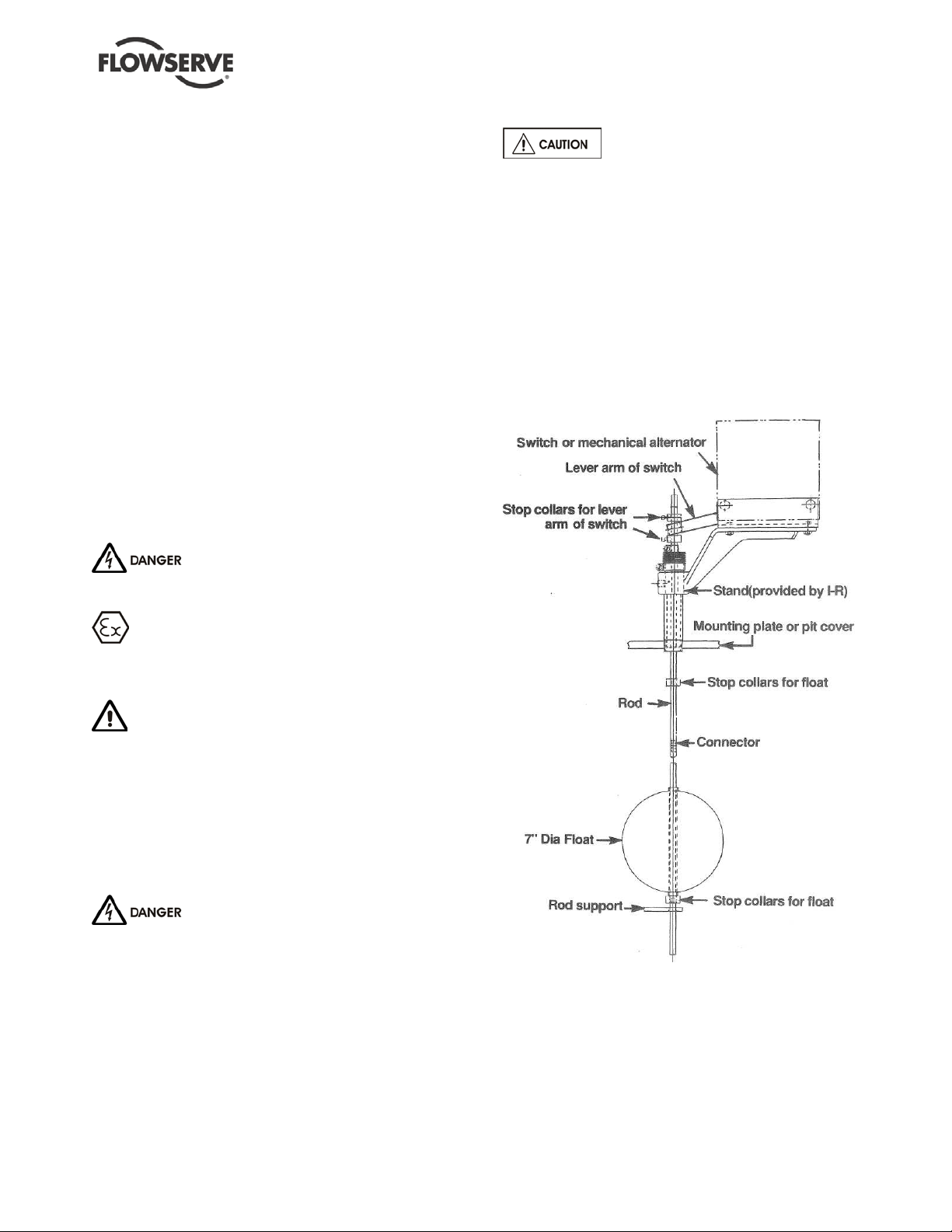
4.8 Level controls
Assemble float control equipment per Figure 4-3
below. Wire the float controls following the
diagrams on the next several pages. The stops
should be set in accordance with maximum and
minimum liquid levels desired and required. Float
rods are furnished in kits of a standard length. The
rod might have to be cut off to fit the particular
installation.
FIGURE 4-3
Electrical connections must be made
by a qualified Electrician in accor dance w ith
relevant local national and internat io na l regula tio ns .
It is important to be aware of the EUROPEAN
DIRECTIVE on potentially explosive areas wher e
compliance with IEC60079-14 is an additional
requirement for making electrical connections.
It is import ant to be aw are of the EUR OPEAN
DIRECTIVE on ele ct ro magne ti c c o mpat i bili ty w hen
wiring up and installing equipment on site.
Attention mus t be pai d to ensure tha t the te chniques
used during wiring/installation do not increase
electromagnetic emissions or decrease the
electromagnetic immunity of the equipment, wiring or
any connected d evi ce s. I f i n any do ubt contact
Flowserve for advice.
The motor must be wired up in
accordance with the motor m anuf ac tur er' s
instructions (normally supplied within the terminal
box) including any temperature, earth leakage,
current and other protective devices as appropriate.
The identification nameplate should be checked to
ensure the power supply is appropriate.
Some of the wiring diagrams are included on the
following pages. If the wiring diagram needed is not
included, contact control manufacturer for wiring
instructions.
Page 19 of 64
Page 20

ESP2 USER INSTRUCTIONS ENGLISH PCN-(71569292) 4-12
SQUARE "D" CLASS 9036
TYPE GG, DR, DW, GR AND GW - FLOAT SWITCH
(Typical Only)
SQUARE "D" CLASS 9038
TYPE AG, AW, AR - MECHANICAL
ALTERNATOR (Typical Only)
OPTIONAL SQUARE "D" FORM N5
HIGH LEVEL ALARM FOR USE WITH CLASS
9038 MECHANICAL ALTERNATOR (Typical Only)
Page 20 of 64
Page 21

ESP2 USER INSTRUCTIONS ENGLISH PCN-(71569292) 4-12
MAGNATROL®
FOR SINGLE FUNCTION (A10) SWITCHES
(Typical Only)
Page 21 of 64
Page 22

ESP2 USER INSTRUCTIONS ENGLISH PCN-(71569292) 4-12
MAGNATROL®
FOR DOUBLE FUNCTION (B10) SWITCHES
(Typical Only)
Page 22 of 64
Page 23

ESP2 USER INSTRUCTIONS ENGLISH PCN-(71569292) 4-12
MAGNATROL®
FOR DOUBLE FUNCTION (B10) SWITCHES
(Typical Only)
Page 23 of 64
Page 24

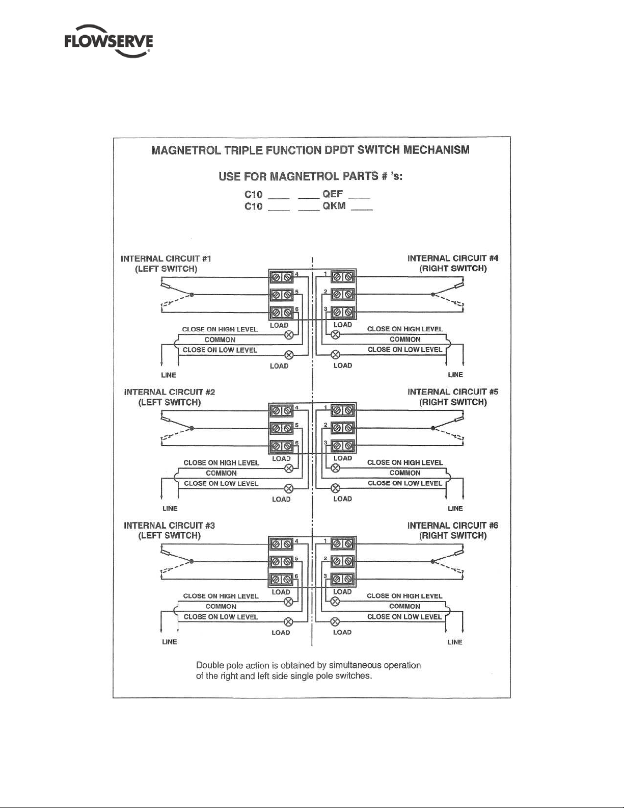
ESP2 USER INSTRUCTIONS ENGLISH PCN-(71569292) 4-12
MAGNATROL®
FOR TRIPLE FUNCTION (C10) SWITCHES
(Typical Only)
Page 24 of 64
Page 25
ESP2 USER INSTRUCTIONS ENGLISH PCN-(71569292) 4-12
MAGNATROL®
FOR TRIPLE FUNCTION (C10) SWITCHES
(Typical Only)
Page 25 of 64
Page 26

ESP2 USER INSTRUCTIONS ENGLISH PCN-(71569292) 4-12
APEX SWITCH
(Typical Only)
Page 26 of 64
Page 27

ESP2 USER INSTRUCTIONS ENGLISH PCN-(71569292) 4-12
4.9 Protection systems
The following protection systems are
recommended particularly if the pump is installed in a
potentially explosive area or is handling a hazardous
liquid. If in doubt consult Flowserve.
If there is any possibility of the system allowing the
pump to run against a closed valve or below
minimum continuous safe flow a protection device
should be installed to ensure the temperature of the
liquid does not rise to an unsafe level.
If there are any circumstances in which the system
can allow the pump to run dry, or start up empty, a
power monitor should be fitted to stop the pump or
prevent it from being started. This is particularly
relevant if the pump is handling a flammable liquid.
If leakage of product from the pump or its associated
sealing system can cause a hazard it is
recommended that an appropriate leakage detection
system is installed.
To prevent excessive surface temperatures at
bearings it is recommended that temperature or
vibration monitoring is carried out.
5 COMMISSIONING, STARTUP, OPERATION AND SHUTDOWN
These operations must be carried
out by fully qualified personnel .
5.1 Pre-commissioning procedure
5.1.1 Pre start-up checks
Prior to starting the pump it is essential that the
following checks be made. These checks are all
described in detail in the Maintenance section of this
manual.
• Pump and motor properly secured to the
baseplate
• All fasteners tightened to the correct torque (see
section 6.5)
• Coupling guard in place and not rubbing
• Rotation check (see sections 4.5 and 5.4).
This is absolutely essential
• Impeller clearance setting
• Shaft seal (if supplied) proper l y instal led
• Seal support system (if supplied) operational
• Bearing lubrication
• Pump instrumentation is operational
As a final step in preparation for operation, it is
important to rotate the shaft by hand to be certain that
all rotating parts move freely, and that there are no
foreign objects in the pump casing.
5.1.2 Packing and mechanical seals
Pumps supplied with vapor proof construction or
pressurized design are furnished with an upper
stuffing box (4100) equipped to take mechanical
seals or packing (See Vapor Proof and Pressurized
Design cross-sections in section 8).
5.1.2.1 Installing mechanical seals
Mechanical seals (4200) are usually shipped
separately to prevent damage during shipment. To
install the seal some disassembly will be required
(Split seals require no disassembly and only steps e.
and f. should be followed).
a) Unbolt the support head (3160) from the bearing
bracket (3130).
b) Unbolt the thrust bearing holder (3110) and
disconnect the thrust bearing assembly (3712,
3031) (Do not remove the thrust bearing (3031)
from the sleeve (3712)).
c) Remove the bearing bracket (3130).
d) If the pump comes with the gland (4120.2)
already on the stuffing box (4100), then it must
be removed at this time before the seal c an be
set in the stuffing box.
e) Temporarily wrap Teflon tape on the shaft
threads to protect the seal from damage while
being slid on the shaft.
f) CAREFULLY slip the seal (4200) onto the shaft
(2100) and slide it down until it sets into the
stuffing box (4100). DO NOT SET THE SEAL
AT THIS TIME.
g) Slip the gland (4120.2) over top the stuffing box.
Leave the gland and seal (4200) loose on the
shaft for now.
h) Reassemble the bearing bracket (3130), then
the thrust bearing assembly (3712, 3031), thrust
bearing holder (3110) , and f inall y the support
head (3160).
i) The impeller must be set before the seal. Follow
the directions listed in section 5.3.
j) Now the seal can be set. For the proper seal
setting consult Figures 5.1 and 5.2. If the seal
being used is not contained in the seal settings
chart, follow the seal manufacturer's instructions
and drawings furnished with the mechanical
seal.
Seals must never be run without
lubrication. Abrasive lubrication will greatly
reduce seal life.
Page 27 of 64
Page 28

mm mm
REQUIRING
In. In.
NO SETTING
Durametallic:
Durametallic:
John Cran e:
Group 1 RAC
52.3
Group 1 PSS
0.0
T-1 double
Group 2 RAC
52.3
Group 3 PSS
0.0
Cartridge T-1B
2.06
Chesterton:
88
Group 3 RAC
71.4
Group 1 221
1.6
88S
2.81
0.0625 28LD
Group 1 VO
73.2
Group 2 221
1.6
1215
2.88
0.0625 2215
Group 2 VO
76.2
Group 3 221
1.6
Flexibox:
3.00
0.0625 FFET
Group 3 VO
John Cran e:
Sealol:
John Crane:
Group 1 8B2
44.5
611
Group 2 37FS
50 1.750 623
1.968
Group 2 8B2
44.5
Borg-Warner:
Group 3 37FS
50 1.750 Uniseal I
1.968
Group 3 8B2
44.5
Uniseal II
1.750
Durametallic:
X-100 X-200 P-50
CRO double
Chesterton:
123
155
241
Packing Information
Group 1
Group 2
Group 3
Packing size, square (inches)
0.31
0.31
0.38
Packing arrangement
2-C-3
2-C-3
2-C-3
Seal Cage width
0.50
0.75
0.50
Shaft Diameter
1.125
1.500
1375
1873
Shaft
ESP2 USER INSTRUCTIONS ENGLISH PCN-(71569292) 4-12
A variety of seal piping plans designed to suit certain
pumping conditions and liquids are available.
FIGURE 5-1
FIGURE 5-2
SEAL
X1
2.06 Group 2 PSS
SEAL
X2
0.0
SEALS
1100
5.1.2.2 Packing the stuffing box
Inspect the stuffing box to see if it contains packing.
The pump normally leaves the factory with the
stuffing box unpacked, and it must be packed before
the pump is put into service. A complete set of
packing cut to proper lengths is included with other
loose parts in a box attached to the pump skid. The
stuffing box should be packed in the following
manner:
a) Remove (or raise out of the way) the stuffing box
gland.
b) Carefully clean the stuffing box (with a lint free
doth) clear of any scale build up and foreign
matter which may have entered during shipment
or storage.
c) In packing the stuffing box put in one ring at a
time, pushing it well into place. Two rings of
packing must be installed, and then the seal
cage, then succeeding rings of packing until the
box is filled. THE JOINTS OF SUCCEEDING
RINGS MUST BE STAGGERED. See Figure 5.3
for additional packing information.
d) After the last ring of packing is in place, draw up
the nuts on the gland (4120.1) evenly finger
tight, then tighten nuts an extra 1/4 turn to initially
set the packing. A slight amount of leakage
through the gland is necessary for proper
lubrication. Packing glands must never be
tightened to the point where leakage from the
packing is stopped.
e) Preserve any left over packing for future use.
After the packing has been compressed under
operating conditions, there may be enough room
to allow another ring to be inserted.
255
There is a tapped hole leading into
the stuffing box for the purpose of sealing the
packing with liquid or grease. When the packing is
compressed, the seal cage must be in line with this
passage.
Shutting off leakage flow from the
packin g wi ll result in bur ned packing and scored
shafts.
FIGURE 5-3
1.123 1498
Page 28 of 64
Page 29

ESP2 USER INSTRUCTIONS ENGLISH PCN-(71569292) 4-12
5.2 Bearing Lubrication
Operation of the unit without proper
lubrication can result in overheating of the bearings,
bearing failures, pump seizures and actual breakup of
the equipment exposing operation personnel to
personal injury.
Check to see that connections are made to
lubrication fittings at pump manifold (3869) on
mounting plate (6110).
5.2.1 Line Shaft Bearings
Check to see that no damage has occurred to any
lubrication lines above and below the mounting plate
(6110) during shipment or installation. For number of
bearings, refer to Figure 5-5 on next page.
5.2.1.1 External Flush Lubrication
a) Clean cool [<70C (160F)] liquid from an external
source must be used when pumps are furnished
with external flush lubrication connections.
b) Check to see that connections are made to
lubrication fittings on pump manifold (3869) on
mounting plate (6110) and that 1.9 LPM (0.5
gpm) of flushing fluid per bearing (See Figure 5-
5) at 1.4 kg/cm
sump pressure.
bearings be wet at all times during operation.
5.2.1.2 Product Lubrication
When conditions warrant, the pump can be furnished
with provisions for pumped product bearing
lubrication. This is accomplished by means of a
lubrication line from the discharge flange of the pump
casing (1100) to the adapter bearing (3020.2), while
the rest of the lines are run from the manifold (3869)
on the pump mounting plate (2025). In the case of a
pumped-product lubricated pump with separators
furnished, all lube lines will be run from the pump
manifold (3869).
a) Check to see that connections are made to
lubrication fittings at pump manifold (3869) on
mounting plate (6110) and for the adapter
(1340.1) bearing (3020.2).
b) Check that 1.9 LPM (0.5 gpm) of pumped liquid
per bearing (See Figure 5-5) at 1.4 kg/cm
PSIG) for standard pr o duct lubricated pumps or
1.8 kg/cm
separators is available.
2
(20 PSIG) above maximum
It is absolutely necessary that rubber
2
(20
2
(25 PSIG) for product lubr icated with
5.2.1.3 Grease Lubrication
Pumps furnished with grease lubricated shaft
bearings (3020.1&.2) will leave the fac tor y with lube
lines (3840.1) and bearings (3020.1&.2) already
packed with grease. The grease used will be of a
water- resistant nature. Each bearing should be
regreased prior to start-up through the grease fittings
located in the manifold (3869) on the pump mounting
plate (6110). Grease must be insoluble in the liquid
being pumped. The recommended grease to be used
is Keystone 81 EP-2 or an equivalent. Keystone 81
EP-2 is the grease that is packed in the bearing
lubrication lines before the pump leaves the factory.
Consult local lubricant suppliers for the type of grease
most compatible with the liquid being pumped. The
grease lubrication system is the same as the external
flush system with the exception of the manifold
(3869). For grease lubrication the manifold contains
grease fittings while the external flush manifold
contains fluid line taps.
5.2.2 Thrust Bearing
The external thrust bearing will either be a
regreaseable bearing (3031), in which case it will
leave the factory with grease already packed, or it will
be a shielded bearing (greased-for-life). For a
regreaseable thrust bearing, it is suggested that the
bearing be dregreased before starting the unit. A
moisture-resistant, lithium-base grease of Number 2
consistency should be used. A shielded bearing will
not need to be degreased, but will need to be
replaced when it becomes excess ivel y worn.
Any unusual nois e or vibratio n fro m the thrust
bearing may mean the beari ng is rea dy for repla cement
and the pump should be dismantled and bearing
checked, and/or replaced.
5.2.3 Driver Bearings
Driver Bearings should be regreased before starting
the pump. Consult the manufacturer's directions for
lubricating instructions .
FIGURE 5-4: Recommended lubricants
Line Shaft
Bearings
Thrust
Bearing and
motor
External flush, product being pumped, or
Keystone 81 EP-2 grease or equivalent
A moisture-res i st ant, lit hi um-base grease of
Number 2 consistency.
Page 29 of 64
Page 30

ESP2 USER INSTRUCTIONS ENGLISH PCN-(71569292) 4-12
GROUP 1
GROUP 2
GROUP 3
GROUP 3
PIT EXCEP T 6 X4 X13
6X4X13
2’-0" 1 1 1 1
2'-6"
1 1 1 1
3'-0"
1 1 1 1 1
1
3'-6"
1 1 1 1 1 1 1
1
4'-0"
2 1 1 1 1 1 1 1 4'-6"
2 1 2 1 1 1 1 1 5’-0”
2 1 2 1 1 1 1
1
5'-6"
2 2 2 2 1 1 1 1 6’-0”
2 2 2 2 1
1 ' 1 1
6'-6"
3 2 2 2 1 1 1
1
7’-0”
3 2 2 2 1 1 2
2
7'-6"
3 2 3 2 2 2 2
2
8'-0" 3 2 3 2 2 2 2 2
8'-6"
3 2 3 2 2 2 2 2 9'-0"
4 2 3 2 2 2 2
2
9'-6"
4 3 3 3 2 2 2
2
10'-0"
4 3 3 3 2 2 2
2
10'-6"
4 3 4 3 2 2 2 2 11'-0"
4 3 4 3 2 2 2
2
11'-6"
5 3 4 3 2 2 2
2
12’-0” 5 3 4 3 2 2 3
3
12'-6"
5 3 4 3 3 3 3 3 13'-0"
5 3 4 3 3 3 3
3
13'-6"
5 4 5 4 3 3 3
3
14'-0"
6 4 .5 4 3 3 3
3
14'-6"
6 4 5 4 3 3 3
3
15'-0" 6 4 5 4 3 3 3
3
15'-6"
6 4 5 4 3 3 3
3
16'-0"
6 4 5 4 3 3 3
3
16'-6"
7 4 6 4 3 3 3 3 17'-0"
7 4 6 4 3 3 4 4 17'-6"
7 5 6 5 4 4 4
4
18’-0”
7 5 6 5 4 4 4
4
18'-6"
7 5 6 5 4 4 4 4 19'-0"
8 5 6 5 4 4 4 4 19'-6"
8 5 7 5 4 4 4
4
20'-0" 8
5 7 5 4 4 4 4
MAX. BRG.
FIGURE 5-5: Number of lineshaft bearings for standard span
DEPTH
3600 RPM
1800 RPM 3600 RPM 1800 RPM 1800 RPM 1200 RPM 1800 RPM 1200 RPM
SPAN
The above numbers include the bottom adapter bearing. For determining the required number of
lineshaft bearing lubrication points, use the total quantity of lineshaft bearings on this sheet.
These spans meet the requirements of API 610, 7th Edition.
30"
48"
36"
Page 30 of 64
48"
60"
60"
60"
60"
Page 31

ESP2 USER INSTRUCTIONS ENGLISH PCN-(71569292) 4-12
Interval
21 cm
(1.3 in.3)
47 cm
(2.9 in.3)
Group 1
50 g (1.8 oz.)
20 g (0.7 oz.)
Group 2
75 g (2.7 oz.)
30 g (1.1 oz.)
Group 3
115 g (4.1 oz.)
45 g (1.6 oz.)
Do not overfill the motor or pump
thrust bearings with grease. If too much grease is
pumped into the bearings, they can overheat. The
maximum temperature that a rolling element bearing
should be exposed to is 105 °C (220 °F).
FIGURE 5-6: Thrust bearing lubrication intervals*
Lubricant Under 71 °C**
(160 °F)
Grease 6 months 3 months 1.5 months
* Assuming good maintenance and operation practices, and no
contamination.
** Bearing housing skin temperature.
71-80 °C
(160-175 °F)
80-94 °C
(175-200 °F)
FIGURE 5-6a: Line bearing grease lubrication*
Pumpage
* Interval depends upon process conditions.
* Check grease cups daily.
Clean Contains abrasives
8 hours 4-6 hours
Figure 5-6b: Line bearing lubrication amounts
Location Amount
Intermediate Bearings [3020.1]
Bottom Bearing [3020.2]
18 grams (0.63 oz.)
3
11 grams (0.38 oz.)
3
Figure 5-6c: Ball bearing lubrication amounts
Group Size Initial lube Re-lubrication
*If new bearings are not lubricated, they should be packed prior to
installation and the housing lubricated as described above.
Grease lubricated line bearings require frequent
lubrication. Grease lubricating systems may be
utilized. Follow the manufacturer’s instruction for
proper use. Lubrication intervals and amounts can be
in Figures 5-6a and 5-6b.
Flowserve offers two lubrication systems that
significantly extend the line shaft bearing lubrication
intervals. Individual 2 oz. grease cups per line shaft
bearing and a fully automated progressive lubrication
systems. Consult your Flowserve representative for
additional information.
5.3 Setting the Impeller Clearance
a) If not already done, turn off driver power and
lock it out so that the driver cannot be started
during impeller (2200) setting.
b) Rotate the shaft (2100) so that the impeller
adjustment key (6700.3) is toward you.
c) Remove the retaining ring (2530.2) and key
(6700.3) from the adjusting sleeve (1881).
d) Holding the shaft (2100) steady, turn the
adjusting sleeve (3712) counterclockwise until
the impeller (2200) is resting against the running
face of the casing (1100).
e) Back the impeller (2200) off the casing (1100) by
rotating the adjusting sleeve (3712) clockwise so
that the next slot lines up with one of the shaft
keyways:
For Groups 1 and 2, continue to rotate the sleeve
(3712) in the same direction for another four or five
combinations of shaft keyway/sleeve slots (22.5
degrees each - the ke ywa y that lines up will alter nat e
as the sleeve (3712) is turned).
For Group 3, continue to rotate the sleeve (3712) in
the same direction for six or seven more
combinations of shaft keyway/sleeve slots (the
keyway that lines up will alternate as the sleeve
(3712) is turned).
f) Install the impeller adjustment key (6700.3) and
retaining ring (2530.2) back into position.
g) Check for freedom of shaft (2100) rotation by
turning by hand.
Grease for life bearings
Double shielded or double sealed bearings
These bearings are packed with grease by the
bearing manufacturer and should not be relubricated.
The replacement interval for these bearings is greatly
affected by their operating temperature and speed.
Shielded bearings typically operate cooler.
Page 31 of 64
Page 32

ESP2 USER INSTRUCTIONS ENGLISH PCN-(71569292) 4-12
5.4 Direction of rotation
5.4.1 Rotation check
It is absolutely essential that the
rotation of the motor be checked before connecting
the shaft coupling. Incorrect rotation of the pump, for
even a short time, can dislodge and damage the
impeller, casing, shaft and shaft seal. All ESP pumps
turn clockwise as viewed from the motor end. A
direction arrow is cast on the front of the casing and
support head [3160] as shown in Figure 5-7. Make
sure the motor rotates in the same direction.
FIGURE 5-7
5.4.2 Coupling installation
Turn off the driver power and lock it
out so that the driver cannot be started during the
coupling assembly.
The coupling should be installed as
advised by the coupling manufacturer. Pumps are
shipped without the spacer installed. If the spacer
has been installed to facilitate alignment, then it must
be removed prior to checking rotation. Remove all
protective material from the coupling and shaft before
installing the coupling.
5.5 Guarding
Power must never be applied to the
driver when the coupling guard is not installed.
The pump must not be operated
without an approved coupling guard in place. Failure
to observe this warning could result in injury to
operating personnel.
Flowserve coupling guards are safety devices intended
to protect workers from inherent dangers of the rotating
pump shaft, motor shaft and coupling.
It is intended to prevent entry of hands, fingers or other
body parts into a point of hazard by reaching through,
over, under or around the guard. No standa rd coupli ng
guard provides complete protection from a
disintegrating co upling . Flowse rve cannot guarantee
their guards will completely contain an exploding
coupling.
For ESP pumps, install the coupling guard with the
connecting hardware.
5.6 Priming and auxiliary supplies
The fluid moving components (casing, impeller, and
adaptor) of ESP pumps should be submerged during
normal operation, so priming is not an issue.
Depending on the bearing lubrication options and the
shaft sealing options, some auxiliary supply lines may
need to be brought to the ESP pump. Check to see if
any other connections need to be made to pump,
such as injection water to stuffing box for seal or
packing lubrication (when furnished) and make the
required connections.
5.7 Starting the pump
All steps within section 4.0 “INSTALLATION” and
section 5.1 "PRE-COMMISSION PROCEDURE"
must be complete before initiating the pump starting
procedure.
To avoid pump da mage or inju ry to
operating personnel during start-up and operation:
• DO NOT operate the pump outsid e of de sign
parameters.
• DO NOT run with a closed discharge for more than
one minute.
• DO NOT operate with sa fety device s (i.e. coupli ng
guard) removed.
• DO NOT run the pump dry.
After all pre-starting checks have been performed, the
pump is ready to start. Observe the following procedu re
to put the pump into ope ration:
a) Rotate the pump shaft by hand through at lea st one
complete revolution to see that the re is no rub or
bind.
b) Check the discharge piping and destination of the
flow.
c) Check the sump liquid level. Liquid level mus t be
sufficient enough to engul f the casin g and adap ter
d) Close, or leave open very slightly, t he control valve in
the discharge line.
e) If external flush-lubricated bearings are used, turn on
water supply to the bearings.
Page 32 of 64
Page 33

ESP2 USER INSTRUCTIONS ENGLISH PCN-(71569292) 4-12
f) Turn on other au xiliary lines (if r equired) such as
stuffing box injection or mechanical seal flush.
g) Start the driver. If othe r than motor drive, bring the
pump up to speed quickly .
h) As soon as the pump is up to rated spe ed, open the
discharge valve slowly, to desired capacity or
pressure keeping in mind the minimum
continuous flow listed in section 3.4.
i) Check all joints and mechanical seal (if
furnished) for leakage.
j) If packing is furnished, adjust the packing gland
and flush flow.
k) Check for excessive vibration.
l) Monitor bearing temperature until it stabilizes.
It is i mportant that the discharge val ve be
opened within a short inte rval afte r sta rting the drive r.
Failure to do this coul d cause a dang erous build up of
heat, and possibly an explo sion.
5.8 Running or operation
5.8.1 Operating Checks
Costly shut-downs will be avoided by making routine
checks on pump operation.
a) Check to see if liquid is being discharged. A
discharge pressure gauge is an easy way to
check whether or not the liquid is being pumped.
If, at any time, the gauge should drop to zero, or
register an abnormally high pressure, shut down
the pump immediately.
b) Observe pump for any abnormal noise or
vibration. Especially check for any CHANGE in
pump noise or vibration.
c) Bearing lubricating liquid or grease and sealing
and cooling liquid flows, should be checked
frequently.
5.8.2 Minimum continuous flow
Minimum continuou s stable flow is the lowe st flow at
which the pump can operate and still meet the bearing
life, shaft deflection and bearing housing vibration limits
documented in the latest version of ASME B73.1M.
Pumps may be operated at lower flows, but it must be
recognized that the pump may exceed one or more of
these limits. For example, vibration may exceed the
limit set by the ASME standard. The size of the pump,
the energy absorbed, and the liquid pumped are some
of the considerations in determining the minimum
continuous flow (MCF).
The minimum continuous flow (capacity) is established
as a percentage of the best efficiency point (BEP). (See
section 3.4.1.)
5.8.3 Minimum thermal flow
All ESP pumps also have a minimum thermal flow.
This is defined as the minimum flow that will not
cause an excessive temperature rise. Minimum
thermal flow is application dependent.
Do not operate the pump below
minimum thermal flow, as this could cause an excessive
temperature rise. Contact a Flowserve sales engineer
for determination o f mini mum thermal flow .
Avoid running a c en tri fugal pu mp at d ras ti cally reduced
capacities or w it h di schar ge valve closed for extended
periods of time. This can cause severe temperature
rise and the li qui d in t he pu mp may reach i t s boil ing
point. If this occurs, the mechanical seal will be
exposed to vapor, with no lub ricati on , and may score or
seize to the stationa ry parts . Continued ru nning unde r
these conditions when the suctio n valve i s also closed
can create an explosiv e conditio n due to the confined
vapor at high pressure and temperature.
Thermostats may be used to sa fegua rd again st
overheating by shutting down t he pu mp at a
predetermined temperature.
Safeguards should also be taken again st possible
operation with a closed discharge valve, such as
installing a bypass back to the suction source. The size
of the bypass line and the requi red by pass flow rate is a
function of the input horsepower and the allowable
temperature rise. The bypass line must alway s enter the
sump (pit) at a point below the li quid level to prev ent air
entrainment.
5.8.4 Reduced head
Note that when discharge head drops, the pump’s
flow rate usually increases rapidly. Check motor for
temperature rise as this may cause overload. If
overloading occurs, throttle the discharge.
5.8.5 Surging condition
A rapidly closing discharge valve can cause a
damaging pressure surge. A dampeni ng
arrangement should be provided in t he pi ping.
5.8.6 Operation in sub-freezing conditions
When using the pump in sub-freezing conditions
where the pump is periodically idle, the pump should
be properly drained or protected with thermal devices
which will keep the liquid in the pump from freezing.
The pump unit must not be operated
above the nameplate conditions. Such operation
could result in unit failure and injury to personnel.
Page 33 of 64
Page 34

Vibration velocity –
unfiltered
mm/s (in./s)
r.m.s.
mm/s (in./s)
Peak value
Normal N
5.6 (0.22)
8.0 (0.31)
Alarm N x 1.25
9.0 (0.35)
12.7 (0.50)
Shutdown N x 2.0
11.3 (0.45)
16. (0.63)
ESP2 USER INSTRUCTIONS ENGLISH PCN-(71569292) 4-12
5.8.7 Normal vibration levels, alarm and trip
Alarm and trip values for installed pumps should be
based on the actual measurements (N) taken on site
on the motors of vertical pumps in fully commissioned
as new condition. The example (N) value is given for
the preferred operating flow region (typically this may
extend to 70 to 120% of the pump best efficiency
point); outside the preferred flow region the actual
vibration experienced may be multiplied by up to two.
These standard values can vary with the rotational
speed and the power absorbed by the pump. For any
special case, contact your nearest Flowserve office.
Measuring vibration at regular intervals will show any
deterioration in pump or system operating conditions.
5.9 Stopping and shutdown
The pump should be shut down
rapidly, especially on pumps equipped with productlubricated bearings.
Pumps driven by electric motors do not require any
special shut-down procedure. If turbine drive is used,
the operator must manually trip the over speed trip to
obtain rapid shut-down. Close the gate valve in the
discharge line if maintenance work is to be done on
pump.
5.10 Hydraulic, mechanical and electrical duty
5.10.1 Net positive suction head (NPSH)
Net positive suctio n head - available (NPSH
measure of the energy in a liquid above the vapor
pressure. It is used to determine the likelihood that a
fluid will vaporize in the pump. It is critical because a
centrifugal pump is designed to pump a liqui d, not a
vapor. Vaporiz ati on in a pump w ill r e sult i n da mage to
the pump, deterioration of the Total differential head
(TDH), and possibly a complete stopping of pumping.
Net positive suction head - required (NPSH
decrease of fluid energy between the inlet of the
pump, and the point of lowest pressure in the pump.
This decrease occurs because of friction losses and
fluid accelerations in the inlet region of the pump and
particularly accelerations as the fluid enters the
impeller vanes. The value for NPSH
) is the
A
) is the
R
for the specific
R
pump purchased is given in the pump data sheet, and
on the pump performance curve.
For a pump to operate properly the NPSH
greater than the NPSH
. Good practice dictates that
R
must be
A
this margin should be at least 1.5 m (5 ft) or 20%,
whichever is greater.
Ensuring that NPSHA is larger than
NPSH
by the suggested margin will greatly enhance
R
pump performance and reliability. It will also reduce
the likelihood of cavitation, which can severely
damage the pump.
5.10.2 Specific gravity (SG)
Pump capacity and total head in meters (feet) of
liquid do not change with SG, however pressure
displayed on a pressure gauge is directly proportional
to SG. Power absorbed is also directly proportion al
to SG. It is therefore important to check that any
change in SG will not overload the pump driver or
over pressurize the pump.
5.10.3 Viscosity
For a given flow rate the total head reduces with
increased viscosity and increases with reduced
viscosity. Also for a given flow rate the power
absorbed increases with the increased viscosity, and
reduces with reduced viscosity. It is important that
checks are made with your nearest Flowserve office if
changes in viscosity are planned.
5.10.4 Pump speed
Changing the pu mp spee d affe ct s flow , t ota l h ead ,
power absorbed, NPS H
, noise and vib rati on lev el s.
R
Flow varies in direct pr oportio n to pump speed . Head
varies as speed ratio squared. Power varies as speed
ratio cubed. If increasing speed it is important to ensure
the maximum pump working pressure is not exceeded,
the driver is not overloaded, NPSH
> NPSHR and that
A
noise and vibr ati on a re w ithin lo cal requi r e ments and
regulations.
5.10.5 Minimum submergence
Each ESP pump has a minimum submergence
depending on the design conditions of that pump.
See Figure 3-3 in section 3.4 to determine the
minimum submergence based upon pump flow and
suction size. All minimum submergence values are
taken from the bottom of the strainer.
If a tailpipe (1428) is used, the sump
(pit) liquid level must engulf the casing and adapter
wcompletely during start-up.
Page 34 of 64
Page 35

ESP2 USER INSTRUCTIONS ENGLISH PCN-(71569292) 4-12
6 MAINTENANCE
It is the plant operator's responsibility to ensure
that all maintenance, inspection and as s embly work
is carried out by authorize d and qualifie d per sonne l
who have adequately familiarized themselves with
the subject matter by studying this manual in detail.
(See also section 1.6.2.)
Any work on the machine must be performed when it
is at a standstill. It is imperative that the proced ure
for shutting down the machine is followed, as
described in section 5.9 and that the driver power
supply is locked.
On completion of work all guards and safety devices
must be re-installed and made opera ti ve aga in.
Before restarting the machine, the relevant
instructions listed in section 5, Commissioning, start
up, operation and shut down must be observed.
Oil and grease leaks may make the ground
slippery. Machine maintenance must always
begin and finish by cleaning the ground a n d the
exterior of the machine.
If platforms, stairs and guard rails are required for
maintenance, they must be placed for easy access to
areas where maintenance and inspection are to be
carried out. The positioning of these accessories
must not limit access or hinder the lifting of the part to
be serviced.
When air or compressed inert gas is used in the
maintenance process, the operat or and an yone in the
vicinity must be careful and have the appropriate
protection. Do not spray air or compressed inert gas
on skin. Do not direct an air or gas jet towards other
people. Never use air or compressed inert gas to
clean clothes.
Before working on the pump, take measures to
prevent the pump from being accidentally started.
Place a warning sign on the starting device:
"Machine under repair: do not start."
With electric drive equipment, lock the main switch
open and withdraw any fuses. Put a warning sign on
the fuse box or main switch:
"Machine under repair: do not connect."
Never clean equipment with flammable solvents or
carbon tetrachloride. Protect yourself against toxic
fumes when using cleaning agents.
Refer to the parts list shown in section 8 for item
number references used throughout this section.
6.1 Maintenance schedule
It is recommended that a maintenance plan and
schedule be implemented, in accordance with these
User Instructions, to include the following:
a) Any auxiliary systems installed must be monitored,
if necessary, to ensure they function correctly.
b) Gland packing must be adjusted correctly to give
visible leakage and concentric alignment of the
gland follower to prevent excessive temperature
of the packing or follower.
c) Check for any leaks from gaskets and seals. The
correct functioning of the shaft seal must be
checked regularly.
d) Check bearing lubricant level, and the remaining
hours before a lubricant change is required.
e) Check that the duty condition is in the safe
operating range for the pump.
f) Check vibration, noise level and surface
temperature at the bearings to confirm
satisfactory operation.
g) Check dirt and dust is removed from areas
around close clearances, bearing housings and
motors.
6.1.1 Preventive maintenance
The following sections of this manual give instructions
on how to perform a complete maintenance overhaul.
However, it is also important to periodically repeat the
Pre start-up checks listed in section 5.1. These
checks will help extend pump life as well as the
length of time between major overhauls.
6.1.2 Need for maintenance records
A procedure for keeping accurate maintenance
records is a critical part of any program to improve
pump reliability. There are many variables that can
contribute to pump failures. Often long term and
repetitive problems can only be solved by analyzing
these variables through pump maintenance records.
6.1.3 Cleanliness
One of the major causes of pump failure is the
presence of contaminants in the bearing housing.
This contamination can be in the form of moisture,
dust, dirt and other solid particles such as metal
chips. Contamination can also be harmful to the
mechanical seal (especially the seal faces) as well as
other parts of the pump. For example, dirt in the
impeller threads could cause the impeller to not be
seated properly against the shaft. This, in turn, could
cause a series of other problems.
For these reasons, it is very important that proper
cleanliness be maintained. Some guidelines are
listed below.
Page 35 of 64
Page 36

ESP2 USER INSTRUCTIONS ENGLISH PCN-(71569292) 4-12
• The work area should be clean and free from
dust, dirt, oil, grease etc.
• Hands and gloves should be clean.
• Only clean towels, rags and tools should be
used.
6.2 Spare parts
The decision on what spare parts to stock varies greatly
depending on many factors such as the criticality of the
application, t he ti me requi r ed to buy a nd re ceive n ew
spares, the erosive/corrosive nature of the application,
and the cost of the spare part. Section 8 identifies all of
the components that make up each pump addressed in
this manual.
6.2.1 Ordering of spare parts
Flowserve keeps records of all pumps that have been
supplied. Spare parts can be ordered from your local
Flowserve sales engineer or from a Flowserve
distributor or representative. When ordering spare
parts the following information should be supplied:
1) Pump serial number
2) Pump size and type
3) Part name – see section 8
4) Part item number – see section 8
5) Material of construction (alloy)
6) Number of parts required
The pump size and serial number can be found on
the nameplate located on the bearing housing. See
Figure 3-1.
6.3 Recommended spares and consumable items
Figure 6-1 shows the parts which are inclu ded in
each of the following three classes of recommended
spares:
CLASS 1 - MINIMUM - Suggested for Domestic
Service when pump is handling clean non-corrosive
liquids and where interruptions in continuity of service
are not objectionable.
CLASS 2 - AVERAGE - Suggested for Domestic
Service when pump is handling abrasive or corrosive
liquids and where some interruptions in continuity of
service are not objectionable.
CLASS 3 - MAXIMUM - Suggested for Export Marine
or Domestic Service where interruptions in service
are objectionable.
Our Sales Representative in your area will gladly
review the class of spares best suited to meet your
requirements. When ordering recommended spares,
please provide information specified in section in
6.2.1.
Page 36 of 64
Page 37

Class
Part Number
Description
1 2 3
3031
Thrust bearing
1 1
---
Coupling
1
---
Motor complete (see note 3)
1
4120.1
Gland 1 1 3250
Bearing holder
Note1
Note1
6700.2
Pump key
1
2200
Impeller
1
2500
Seal ring for adapter
1
4200
Mechanical seal (optional)
1 1 1
3712
Adjusting sleeve
1
4610
Impeller o-ring
1
4134
Seal cage -- packed box
1 1
4590.1
Gasket -- casing
1 1 1
4590.3
Gasket -- stuffing box to upper column
1 1 1
---
Gasket -- mechanical seal (optional)
1 1 1
4590.5
Gasket -- column to mounting plate
1 1 1
4590.4
Gasket -- manifold to mounting plate
1 1
4130
Packing (optional)
Note1
Note1
Note1
4310.1
Klozure lip seal -- bearing body
1 1 1
4310.2
Klozure lip seal -- upper column
1 1 1
2100
Pump shaft (see note 2)
1
6531
Strainer
1
6541.3
Impeller washer -- Group 3
1 1
3020.1
Bearing -- intermediate
Note1
Note1
3020.2
Bearing -- adapter (bottom)
1 1
3110
Bearing body -- thrust bearing
1 1
4590.2
Gasket -- discharge pipe to casing flange
1 1 1
FIGURE 6-1: Recommended spare parts
(Reference Figure 8-11)
ESP2 USER INSTRUCTIONS ENGLISH PCN-(71569292) 4-12
Note 1: Check record card for quantity required.
Note 2: Check record card for length required.
Note 3: When ordering motor parts, give motor serial number and model number as read from the motor
nameplate. Also furnish pump serial number.
6.4 Tools required
A typical range of tools that will be required to
maintain these pumps is listed below.
Standard hand tools SAE
• Hand wrenches
• Socket wrenches
• Allen wrenches
• Soft mallet
• Screwdrivers
Page 37 of 64
Specialized equipment
• Bearing pullers
• Bearing induction heaters
• Dial indicators
• Spanner wrench
Page 38

ESP2 USER INSTRUCTIONS ENGLISH PCN-(71569292) 4-12
[6580.2]
Mechanical seal gland studs/nuts, with gasket
⅜ in. – 16 Nm (12 lbf•ft)
⅜ in. – 16 Nm (12 lbf•ft)
½ in. – 41 Nm (30 lbf•ft)
6.5 Fastener torques
FIGURE 6-2: Recommended maximum bolt torques
Item Description Group 1
[6580.2] Mechanical seal gland studs/nuts, with O-ring ⅜ in. – 27 Nm (20 lbf•ft) ⅜ in. – 27 Nm (20 lbf•ft) ½ in. – 54 Nm (40 lbf•ft)
[6580.1] Casing studs/nuts and all other bolting ½ in. – 41 Nm (30 lbf•ft)
Notes: 1. For lubricated or PTFE-coated threads, use 75% of the values given.
2. Gasket joint torque values are for unfilled PTFE gaskets. Other gasket materials may require additional torque to seal.
Exceeding metal joint torque values is not recommended.
6.6 Setting impeller clearan ce and impeller replacement
A new impeller o-ring [4610] must be installed
whenever the impeller has been removed from the
shaft. Impeller clearance settings may be found in
section 5.3. Impeller balancing instruction may be
found in section 6.8.
Do not adjust the impeller clearance with the seal set.
Doing so may result in seal leakage and/or damage.
non-lubricated
6.7.1 Removing pump from pit
a) Close control valve in discharge line.
b) Lock out power supply to driver.
c) Disconnect all electrical connections.
d) Disconnect any external auxiliary piping
connections.
e) Disconnect discharge piping from pump.
f) Disconnect coupling guard and coupling halves.
g) Disconnect driver and remove.
h) Unbolt pump mounting plate (6110) and lift
pump (see Sections 2.3 and 4.4) from pit. Let
the pump drain thoroughly before removing
pump completely. Remove casing drain, if
supplied.
The impeller could have sharp edges,
which could cause an injury. It is very important to
wear heavy gloves when handling an impeller.
i) Remove liquid level controls (if any).
j) Lift the pump (see Sections 2.3 and 4.4) out of
the pit and lay pump horizontally on supports.
Group 2
non-lubricated
½ in. – 41 Nm (30 lbf•ft)
⅝ in. – 81 Nm (60 lbf•ft)
Group 3
non-lubricated
¾ in. – 136 Nm (100 lbf•ft)
⅞ in. – 217 Nm (160 lbf•ft)
It is recommended that two people
install a Group 3 impeller. The weight of a Group 3
impeller greatly increases the chance of thread
damage and subsequent lock-up concerns.
Do not attempt to tighten the impeller
on the shaft by hitting the impeller with a hammer or
any other object or by inserting a pry bar between the
impeller vanes. Serious damage to the impeller may
result from such actions.
Install the impeller [2200] by screwing it onto the shaft
(use heavy gloves) until it firmly seats against the
shaft shoulder.
6.7 Disassembly
Use extreme care in removing and dismantling pump.
Refer to pump assembly drawings for part
nomenclature (see Sect ion 8).
Depending on the product being
pumped, the pump should be washed down and
decontaminated before any work is done on it.
For units that are welded, the welded
sections should not be disassembled unless the parts
need to be replaced.
6.7.2 Pump disassembly
a) Pump discharge pipe removal
• For Groups 1 and 2 and 6x4x13: unscrew the
flange (1245.2), locknut (3712), and loosen
the lower locknut. Then the upper discharge
pipe (1360) can be unscrewed.
• For Group 3 pumps (except the 6x4x13):
unscrew the flange (1245.2). These pumps
are furnished with the discharge pipe bolted
to the mounting plate by a flange (1245.3)
and four screws (6570.11). Remove the
screws holding the flange to the mounting
plate (6110).
• Both: the discharge pipe (1360) can then be
removed by unbolting the elbow (1371) from
the discharge of the casing (1100) and
pulling the discharge pipe out from the under
side of the mounting plate (6110).
Page 38 of 64
Page 39

ESP2 USER INSTRUCTIONS ENGLISH PCN-(71569292) 4-12
b) Remove bearing lubrication lines (3840.1).
c) Unbolt and remove the pump casing (1100).
The strainer (6531) does not need to be
removed from the casing unless it is to be
cleaned or replaced.
d) Remove the impeller (2200) by unscrewing it
counter-clockwise (looking in at the vanes) while
holding the drive coupling with a strap wrenc h.
Do not attempt to use a crowbar as a lever to
unscrew the impeller as damage to the vanes
may result. Use a strap wrench or a piece of
wood as a mallet. The impeller threads are
sealed by an O-ring (4610) which should then be
replaced.
e) Removing the thrus t bear ing:
• Pumps without Vapor Proof or Pressurized
Construction: remove the thrust bearing by
first unbolting the support head (3160). For
groups 1 and 2 the support head will be
disconnected from the mounting plate (6110)
and for group 3 the support head will be
disconnected from the upper column
(1341.1).
Before the next procedure, be sure to
cover the shaft threads with a Teflon tape for
protection when sliding parts off the shaft to prevent
the shaft threads from being damaged or causing
damage to other parts.
f) Unbolt the gland and carefully slide it off the end
of the shaft. If the pump contains a seal, VERY
CAREFULLY, slide the seal off of the shaft. If
the pump contains packing remove the packing
at this time.
g) Now the stuffing box can be unbolted and
removed gently from the shaft.
h) A shaft-bullet (See Figure 6-3) is recommended,
but not required, for the next step. If a shaft
bullet is to be used, attach the bullet in place of
the impeller (2200). Remove the shaft (2100)
from the remainder of the pump.
FIGURE 6.3 Shaft
bullets
For Group 3 pumps, any columns still
attached to the pump at this time must be firmly
supported. The upper column will disconnect from
the mounting plate at the same time that the support
head is disconnected.
• Now remove the thrust bearing holder (3110)
and the thrust bearing assembly (3031, 3712)
by unscrewing the sleeve (3712) from the
shaft (2100).
• Pumps with Vapor Proof or Pressurized
Construction: first remove the support head
(3160) from the bearing bracket (3130). Next
remove the bearing body (3110) and the
thrust bearing assembly (3031, 3712) by
unscrewing the sleeve (3712) from the shaft
(2100). For groups 1 and 2 the bearing
bracket will be disconnected from the
mounting plate (6110) and for group 3 the
bearing bracket will be disconnected from the
upper column (1341.1).
For Group 3 pumps, any columns still
attached to the pump at this time must be firmly
supported. The upper column will disconnect from
the mounting plate at the same time that the support
head is disconnected.
Groups 1, 2, and 6x4x13
Always remove the shaft by pulling it
out through the mounting plate end as shaft threads
may cause damage to the lineshaft bearings if pulled
through the casing end.
i) Unbolt and remove the adapter (1340.1).
j) Unbolt and remove the columns (1341.2) and
the bearing holders (3250) until the upper
column is reached (1341.1).
k) The shaft bearings should not be removed from
their housings unless they are to be replaced.
Table 6.1 shows a listing of allowable bearing
tolerances. If these tolerances are exceeded,
either the bearings (3020.1-.2), shaft (2100), or
bearing holder (3250) should be replaced.
l) Intermediate shaft bearings (3020.1) can be
pressed or driven out of their bearing holder
(3250) when replacing.
m) The adapter bearing (3020.2) may be removed
by pressing or driving the bearing sleeve from
the upper flange (column side) out through the
lower end (casing side) of the adapter (1340.1)
taking the seal ring (2500) with it.
Group 3 (Excluding 6 x4x1 3)
Page 39 of 64
Page 40

ESP2 USER INSTRUCTIONS ENGLISH PCN-(71569292) 4-12
Part
Description
Max. Inside Diameter
Min. Outside Diameter
Group 2 Shaft
37.95 mm (1.494 in.)
Group 3 Shaft
47.47 mm (1.869 in.)
3020
Group 1 Line Shaft Bearings
Solid Carbon
28.994 mm (1.1415 in.)
Bronze
28.766 mm (1.1325 in.)
Teflon
28.956 mm (1.1400 in.)
Iron
28.651 mm (1.1280 in.)
Group 2 Line Shaft Bearings
Solid Carbon
38.557 mm (1.5180 in.)
Metal-backed Carbon
38.329 mm (1.5090 in.)
Bronze
38.329 mm (1.5090 in.)
Rubber
38.367 mm (1.5105 in.)
Group 3 Line Shaft Bearings
Solid Carbon
48.082 mm (1.8930 in.)
Metal-backed Carbon
47.854 mm (1.8840 in.)
Bronze
47.854 mm (1.8840 in.)
Rubber
47.892 mm (1.8855 in.)
Teflon
48.006 mm (1.8900 in.)
Group 2 Bearing Holder/Adapter
50.813 mm (2.0005 in.)
Group 3 Bearing Holder/Adap ter
66.688 mm (2.6255 in.)
FIGURE 6.4 Shaft, bearing, and bearing holder tolerances
2100 Group 1 Shaft
28.42 mm (1.119 in.)
3250
1340.1
Metal-backed Carbon
Rubber
Teflon
Iron
Iron
Group 1 Bearing Holder/Adap ter
28.689 mm (1.1295 in.)
28.766 mm (1.1325 in.)
38.481 mm (1.5150 in.)
38.329 mm (1.5090 in.)
47.854 mm (1.8840 in.)
41.288 mm (1.6255 in.)
6.8 Examination of parts
6.8.1 Cleaning/inspection
All parts should now be thoroughly cleaned and
inspected. New bearings, O-rings, gaskets, and lip
seals must be used. Any parts that show wear or
corrosion should be replaced with new genuine
Flowserve parts.
It is i mpo rtant t hat only non-flammable,
non-contaminated cleani ng fluid s are used. The se
fluids must comply with plant safety and environmental
guidelines.
a) Inspect impeller (2200) for excessive wear and
etching due to corrosion. Large nicks and deep
pits will unbalance the impeller and cause
vibration and wear in other parts of the pump.
Be sure the o-ring (4610) sealing surface and
impeller threads are clean.
b) Check pump shaft (2100) for straightness.
c) Inspect the surface of the shaft in the bearing
(3020.1-.2) areas to make sure it is smooth. It
must be free of grooves, scratches, corrosion or
wear.
d) Check ends of shaft for burrs. Make sure that
shaft threads are clean.
e) Inspect the casing (1100) thoroughly, removing
all burrs and foreign matter. Check hydraulic
passages for cleanliness.
f) Check all other parts for burrs, wear, damage or
corrosion.
g) Use a dial indicator to check the straightness of
the shaft extension of the driver and check
indicator readings against the values given in
Figure 6-5. Should any of these limits be
exceeded, check with the driver manufacturer
for recommended repair or replacement parts.
rrrrrrrrrr
Page 40 of 64
Page 41

A B C
284TCV-286TCV
0.10 (0.004)
0.10 (0.004)
0.08 (0.003)
Impeller Balance
Shaft endplay
n/s
0.05 (0.002)
0.05 (0.002)
ESP2 USER INSTRUCTIONS ENGLISH PCN-(71569292) 4-12
FIGURE 6-5 Motor tolerances
T.I.R. Dimensions -- mm (in.)
Frame Si ze
143TCV-256TCV 0.10 (0.004) 0.10 (0.004) 0.05 (0.002)
324TCV-445TCV 0.18 (0.007) 0.18 (0.007) 0.08 (0.003)
A B C
h) Inspect inside of bearings (3020.1-.2) in the
adapter (1340.1) and intermediate bearing
holder(s) (3250). Check for cracks, uneven or
excessive wear, scoring or heat discol oration,
and corrosion. Bearings should be replaced as
described in Section 6.7.2.
6.8.2 Critical measurements and tolerances
To maximize reliability of pumps, it is important that
certain parameters and dimensions are measured
and maintained within specified tolerances. It is
important that all parts be checked. Any parts that do
not conform to the specifications should be replaced
with new Flowserve parts.
6.8.3 Parameters that should be checked by users
Flowserve recommends that the user check the
measurements and tolerances in Figure 6-6
whenever pump maintenance is performed. Each of
these measurements is described in more detail on
the following pages.
6.8.3.1 Shaft
Replace if grooved, pitted or worn, especially where
the shaft rides in the sleeve bearings.
6.8.3.2 Bearings
It is recommended that rolling element bearings not
be used after removal from the shaft.
6.8.3.3 Impeller balancing
Shaft whip is deflection where the centerline of the
impeller is moving around the true axis of the pump.
It is not caused by hydraulic force but rather by an
imbalance with the rotating element. Shaft whip is
very hard on the mechanical seal because the faces
must flex with each revolution in order to maintain
contact.
To minimize shaft whip it is imperative that the
impeller is balanced. All impellers manufactured by
Flowserve are balanced after they are trimmed. If for
any reason, a customer trims an impeller, it must be
re-balanced. See note 1 under Figure 6-19 regarding
acceptance criteria.
6.8.3.4 Vibration analysis
Vibration analysis is a type of condition monitoring
where a pump’s vibration “signature” is monitored on
a regular, periodic basis. The primary goal of
vibration analysis is extension on MTBPM. By using
this tool Flowserve can often determine not only the
existence of a problem before it becomes serious, but
also the root cause and possible solution.
Modern vibration analysis equipment not only detects
if a vibration problem exists, but can also suggest the
cause of the problem. On a centrifugal pump, these
causes can include the following: unbalance,
misalignment, defective bearings, resonance,
hydraulic forces, cavitation and recirculation. Once
identified, the problem can be corrected, leading to
increased MTBPM for the pump.
Flowserve strongly urges customers to work with an
equipment supplier or consultant to establish an ongoing vibration analysis program. See section 5.8.7
for guidance on vibration monitoring.resfdb
FIGURE 6-6
Suggested
and/or
provided by
Flowserve
mm (in.)
0.013 (0.0005)
Topic
Bearing housing
Diameter (ID) tolerance
at bearings
n/s = not specified.
1. The maximum values of acceptable unbalance are:
1500 r/min: 40 g∙mm/kg (1800 r/min: 0.021 oz-in/lb) of mass.
2900 rpm: 20 g∙mm/kg (3600 rpm: 0.011 oz-in/lb) of mass.
Flowserve performs a single plane spin balance on most
impellers. The following impellers are exceptions: 10X8-13,
10X8-15. On t hese Flowserve performs a two plane dynamic
balance, as required by the ASME B73.1M standard. All
balancing, whether single or two plane, is performed to the ISO
1940 Grade 6.3 tolerance criteria.
2. The ASME B73.1M standard does not specify a recommended
level of alignment. Flowserve recommends that the pump and
motor shafts be aligned to within 0.05 mm (0.002 in.) parallel FIM
(full indicator movement) and 0.0005 mm/mm (0.0005 in./in.)
angular FIM. Closer alignment will extend MTBPM.
ASME
B73.1M
standard
mm (in.)
n/s
Suggested
by majo r
seal
vendors
mm (in.)
See note 1
Page 41 of 64
Page 42

Shaft Diameter
A
28.58 mm (1.125 in.)
3.2 mm (.125 in.)
38.10 mm (1.500 in.)
3.2 mm (.125 in.)
47.63 mm (1.875 in.)
3.2 mm (.125 in.)
Shaft Diameter
A
28.58 mm (1.125 in.)
3.2 mm (.125 in.)
38.10 mm (1.500 in.)
9.5 mm (.375 in.)
47.63 mm (1.875 in.)
3.2 mm (.125 in.)
SHAFT
Holder
SHAFT
Bearing
ESP2 USER INSTRUCTIONS ENGLISH PCN-(71569292) 4-12
6.9 Assembly of pump and seal
It is important that all pipe t hr e ad s be
sealed properly. PTFE tape provides a very reliable
seal over a wide range of fluids, but it has a serious
shortcoming i f not in s tall ed pro pe rly . I f, du ring
application to t he thre ad s, the t ape i s w rapped ov er the
end of the male thread, strings of the tape will be
formed when threaded into the female fitting. These
strings can t hen t ea r away and lodge in the pip ing
system.
If this occurs in the seal flush system, small orifices can
become blocked effectively shutting off flow. For this
reason, Flowserve does not recommend the use of
PTFE tape as a thread sealant.
Flowserve has investigated and tested alternate
sealants and has identified two that provide an
effective seal, have the same chemical resistance as
the tape, and will not plug flush systems. These are
La-co Slic-Tite and Bakerseal. Both products contain
finely ground PTFE particles in an oil based carrier.
They are supplied in a paste form which is brushed
onto the male pipe threads. Flowserve recommends
using one of these paste sealants.
Full thread length engagement is required for all
fasteners.
FIGURE 6-7 Intermediate bearing
FIGURE 6-8 Adapter bearing
Bearing
Refer to Figure 6-5 for recommended bolt
torques.
During reassembly be sure to use new gaskets and
o-rings.
6.9.1 Replacing shaft sleeve bearings
a) After removing the old intermediate bearings
(3020.1) (see section 6.7.2) clean and deburr
bearing holder bore. Appl y a light coating of
grease or oil to bearing holder bore and out-side
diameter of new bearing. Carefully press new
bearing into holder to "A" dimension in Figure 6-
7.
b) After removing the adapter bearing (3020.2) (see
section 6.7.2) clean and deburr adapter bore.
Apply a light coating of grease or oil to bearing
holder bore and outside diameters of new
bearings. Carefully press the sealing ring and new
bearing, respectively, into adapter to "A" dimension
in Figure 6-8.
c) Be sure that all bearings (3020.1-.2) are now
within their bearing holders (3250, 1340.1).
Page 42 of 64
Page 43

ESP2 USER INSTRUCTIONS ENGLISH PCN-(71569292) 4-12
6.9.2 Inserting the shaft using a “shaft bullet” (see Figure 6-3)
a) Standard and vapor tight construction:
connect the upper column (1341.1) to the
mounting plate (6110). For Group 3, the upper
column and support head (3160) must be bolted
to the mounting plate at the same time. Vapor
proof or pressurized construction: replace the
upper column gasket (4590.5) and reconnect the
upper column (1341.1) to the mounting plate
(6110). For Group 3, the bearing bracket (3130)
must be bolted to the mounting plate at the
same time.
b) If intermediate bearings are used, reconnect the
columns (1341.2) and intermediate bearing
holders (3250).
c) Bolt the adapter (1340.1) back onto the last
column in the pump.
d) Screw the shaft bullet onto the end of the shaft
(2100) at the impeller end.
Always insert the shaft from the
mounting plate side o f the pump. Neve r insert it from
the adapter side because shaft threads may cause
damage to the internal bearings.
e) All designs (excluding Group 3 vapor proof
and pressurized): the pump shaft (2100)
should now be inserted into the pump from the
mounting plate side. For Group 3 vapor proof
and pressurized designs: if the lip seal
(4310.1) is still in the bearing bracket (3130),
remove it at this time. Slide the shaft (2100)
through the bearing bracket and down through
the columns. Once the shaft has cleared the
bearing bracket, replace or reins ert the lip seal
into the bearing bracket.
6.9.3 Inserting the shaft without “shaft bullet”
a) Standard and vapor tight construction:
connect the upper column (1341.1) to the
mounting plate (6110). For Group 3, the upper
column and support head (3160) must be bolted
to the mounting plate at the same time. Vapor
proof or pressurized construction: replace the
upper column gasket (4590.5) and reconnect the
upper column (1341.1) to the mounting plate
(6110). For Group 3, the bearing bracket (3130)
must be bolted to the mounting plate at the
same time.
b) All designs except Group 3 vapor proof and
pressurized: insert the shaft from the motor
side of the pump through the starter column
(1341.1) until the shaft threads (for the thrust
bearing - 3031) are about 3 inches from the
starter column. For Group 3 vapor proof and
pressurized: if the lip seal (4310.1) is still within
the bearing bracket (3130), remove it at this
time. Insert the shaft from the motor side of the
pump through the bearing bracket (3130) and
starter column (1341.1) until the shaft threads
(for the thrust bearing - 3031) are about 3 inches
from the starter column. Replace or reinsert the
lip seal (4310.1) into the bearing bracket (3130).
c) Slide the first bearing holder (3250), with bearing
in place, onto the end of the shaft (2100).
d) If intermediate bearings are used, then slide the
rest of the columns (1341.2) and bearings
(3020, 3250) onto the pump.
e) If no intermediate bearings are used on pump,
or after they have all been installed, then slide
the adapter (1340.1) onto the shaft (2100) and
bolt to the starter column (1341.1).
6.9.4 Impeller installation
a) Insert a new o-ring (4610) at base of impeller
(2200) threads.
b) Apply a light coat of grease or oil to impeller
threads as to allow for ease of disassembly in
the future.
c) Using a strap wrench to hold the drive coupling,
screw impeller (2200) onto the end of the pump
shaft (2100) clockwise until snugly fit.
Do not attempt to use a crowbar as a
lever as damage to the vanes may result.
6.9.5 Thrust Bearing Reassembly
(Vapor proof and pressurized designs)
Cover the shaft threads with a Teflon
tape to prevent them from causing internal damage to
other components.
• For Group 1 and 2 pumps: Reattach the
stuffing box (4100) to the upper column. See
section 6.9.6 “Packing" or section 6.9.7
"Mechanical Seal" for next steps.
It is important that the shaft and columns
are well supported after the shaft is partially inserted or
bending in the shaft may occur.
Page 43 of 64
Page 44

ESP2 USER INSTRUCTIONS ENGLISH PCN-(71569292) 4-12
• For Group 3 pumps: Push the shaft towards
the mounting plate until the threads are lined
up with the top of the column. Insert the
stuffing box (4100) from the side and bolt to
the column. If a mechanical seal is being
used, push the shaft up from the adapter
(1340.1) side while pushing the seal (4200)
and gland (4120.2) onto the Teflon taped
threaded end of the shaft from within the
bearing bracket. If packing (4130) is being
used, push the shaft up from the adapter
(1340.1) end while pushing the gland
(4120.1) onto the Teflon taped threaded en d
of the shaft. Leave the gland (4120.2) and
mechanical seal, if furnished, loose on the
shaft for now. DO NOT SET SEAL AT THIS
TIME. See section 6.9.6 “Packing" or section
6.9.7 "Mechanical Seal" for the next steps.
6.9.5 Packing
a) If the pump is furnished with packing, put one
ring in at a time.
b) Two rings should be inserted and then the seal
cage (4134) and then the succeeding rings of
packing until the box is filled.
The joints of succeeding packing rings
must be staggered and the seal cage must line up
with the passage leading into the stuffing box for
proper lubrication.
c) Now slide the gland (4120.1) over the shaft and
draw up the nuts finger tight, then tighten nuts
an extra 1/4 turn.
d) Reattach the thrust bearing assembly (3031,
3712).
e) Reattach the thrust bearing holder (3110).
f) Reattach the support head (3160).
6.9.5 Mechanical Seal
Cover the shaft threads with a Teflon
tape to prevent them from causing internal damage to
the seal.
a) See section 5.1.2.1 for seal installation
directions.
b) Connect the thrust bearing assembly (3031,
3712).
c) Reattach the thrust bearing holder (3110).
d) Reattach the support head (3160).
6.9.5 Casing and discharge piping
a) Place a new gasket (4590.1) on the gasket face
of the adapter (1340.1) where the adapter and
casing (1100) will lin e u p.
b) Bolt the pump casing to the adapter
c) If the strainer (6531) had been removed for
cleaning or replacement purposes, reattach
strainer to suction flange of the casing.
d) Reconnect all bearing lubrication lines (3840.1).
e) For Groups 1, 2, and 6x4x13: At this point the
lower locknut (3712) should be screwed all the
way down the threads on the upper end of the
discharge pipe (1360). The discharge elbow
(1371) should be screwed onto the lower end of
the discharge pipe (if not already). Check to see
if the companion flange (1245.1) is still
connected to the discharge elbow. Next, the
discharge pipe should be slid up through the
mounting plate (6110) until the companion
flange lines up with the discharge flange of the
casing (1100).
To ensure a proper seal at the casing
discharge flange, it is important that the companion
flange is connected to the casing before the upper
locknuts are tightened to against the mounting plate.
f) Replace the gasket (4590.2) between the
companion flange and the discharge flange of
the casing and bolt back together.
g) The upper lock-nut can now be screwed onto
the threads at the upper end of the discharge
pipe and both locknuts can be tightened against
the mounting plate.
h) For Group 3 (excluding 6x4x13): The
discharge pipe is attached the same way to the
casing discharge flange (see step “f” above).
The only difference in the assembly is that the
Group 3 pipes have a flange (1245.3) welded to
the discharge pipe (1360) that bolts to the
underside of the mounting plate (6110).
i) Set the impeller clearance per Section 5.3.
j) See Section 4 and Section 5 for installation and
startup instructions.
Page 44 of 64
Page 45

ESP2 USER INSTRUCTIONS ENGLISH PCN-(71569292) 4-12
Pump not reaching design flow rate
⇓
⇓
Pump not reaching design head (TDH)
⇓
⇓
⇓
⇓
⇓
⇓
Excessive noise from wet end
⇓
⇓
⇓
⇓
⇓
⇓
⇓
⇓
⇓
⇓
⇓
⇓
PROBABLE CAUSES
POSSIBLE REMEDIES
avoid adverse flow rotation as it approaches the impeller.
3. Check for minimum submergence
Speed too low.
Check motor speed against design speed.
inspected before it is restarted.
impeller diameter may require use of a larger motor.)
Impeller clearance too large.
Reset impeller clearance.
4. Clean strainer.
worn, corroded or missing.
disassemble and inspect the pump before operation.
2. Check outboard bearing assembly for axial end play.
7. Check all plugs and tapped openings for tightness.
7 FAULTS; CAUSES AND REME DIES
The following is a guide to troubleshooting problems for the Flowserve ESP pumps. Common problems are
analyzed and solutions offered. Obviously, it is impossible to cover every possible scenario. If a problem
exists that is not covered by one of the examples, then refer to one of the books listed in section 10 Additional
sources of information or contact a Flowserve sales engineer or distributor/representative for assistance.
FAULT SYMPTOM
No discharge or flow with pump running
Pump operates for short period, then loses prime
Excessive noise from thrust bearing end
Pump uses too much power
Insufficient NPSH. (Noise may not be
present.)
System head greater than anticipated.
Entrained air. Air leak from
atmosphere on suction side.
Entrained gas from process. Process generated gases may require larger pumps.
Direction of rotation wrong.
Impeller too small.
Plugged impeller, strainer or casing
which may be due to a product or
large solids.
Recalculate NPSH available. It must be greater than the NPSH
required by pump at desired flow. If not, redesign suction piping,
holding number of elbows and number of planes to a minimum to
Reduce system head by increasing pipe size and/or reducing
number of fittings. Increase impeller diameter. (Note: Increasing
impeller diameter may require use of a larger motor.)
1. Check for air entrainment sources in the sump.
2. If vortex formation is observed in suction tank, install a vortex
breaker.
After confirming wrong rotation, reverse any two of three leads on
a three phase motor. The pump should be disassembled and
Replace with proper diameter impeller. (NOTE: Increasing
1. Reduce length of fiber when possible.
2. Reduce solids in the process fluid when possible.
3. Consider larger pump.
Wet end parts (casing or impeller)
Liquid level in sump too low.
Impeller rubbing.
Damaged pump shaft, impeller. Replace damaged parts.
Liquid vortexing in sump.
Bearing contamination appearing on
the raceways as scoring, pitting,
scratching or rusting caused by
adverse environment and entrance of
abrasive contaminants from
atmosphere.
Speed too high.
Too much flow.
Replace part or parts.
If pump and bearing system has run dry for a long period,
1. Check and reset impeller clearance.
Add sump vortex breakers to avoid adverse fluid rotation as it
approaches the impeller.
1. Work with clean tools in clean surroundings.
2. Remove all outside dirt from housing before exposing bearings.
3. Use clean solvent and flushing oil.
4. Protect disassembled bearing from dirt and moisture.
5. Clean inside of bearing body before replacing bearing.
6. Check lip seals and replace as required.
Adjust VFD or install proper speed motor.
System resistance to flow is too low. Close discharge valve more.
Page 45 of 64
Page 46

Pump not reaching design flow rate
⇓
⇓
⇓
⇓
⇓
⇓
⇓
⇓
⇓
⇓
Excessive noise from thrust bearing end
⇓
⇓
⇓
⇓
⇓
⇓
⇓
⇓
⇓
⇓
races in a stationary bearing.
intervals of one to three months.
the bearing or excessive thrust loads.
the bearing races.
2. Pump shaft bent and binding in sleeve bearings.
Pump not reaching design head (TDH)
No discharge or flow with pump running
Pump operates for short period, then loses prime
Excessive noise from wet end
ESP2 USER INSTRUCTIONS ENGLISH PCN-(71569292) 4-12
Pump uses too much power
PROBABLE CAUSES POSSIBLE REMEDIES
Brinelling of bearing identified by
indentation on the ball races, usually
caused by incorrectly applied forces
in assembling the bearing or by shock
loading such as hitting the bearing or
drive shaft with a hammer.
False brinelling of bearing identified
again by either axial or circumferential
indentations usually caused by
vibration of the balls between the
Thrust overload on bearing identified
by flaking ball path on one side of the
outer race or in the case of maximum
capacity bearings, may appear as a
spalling of the races in the vicinity of
the loading slot. These thrust failures
are caused by improper mounting of
Misalignment identified by fracture of
ball retainer or a wide ball path on the
inner race and a narrower cocked ball
path on the outer race. Misalignment
is caused by poor mounting practices
or defective drive shaft. For example,
bearing not square with the centerline
or possibly a bent shaft due to
improper handling.
Bearing damaged by electric arcing
identified as electro- etching of both
inner and outer ring as a pitting or
cratering. Electrical arcing is caused
by a static electrical charge
emanating from belt drives, electrical
leakage or short circuiting.
Bearing damage due to improper
lubrication, identified by one or more
of the following:
1. Abnormal bearing temperature
rise.
2. A stiff cracked grease appearance.
3. A brown or bluish discoloration of
When mounting the bearing on the drive shaft use a proper size
ring and apply the pressure against the inner ring only. Be sure
when mounting a bearing to apply the mounting pressure slowly
and evenly.
1. Correct the source of vibration.
2. Where bearings are oil lubricated and employed in units that
may be out of service for extended periods, the drive shaft should
be turned over periodically to relubricate all bearing surfaces at
Follow correct mounting procedures for bearings.
Handle parts carefully and follow recommended mounting
procedures. Check all parts for proper fit and alignment.
1. Where current shunting through the bearing cannot be
corrected, a shunt in the form of a slip ring assembly should be
incorporated.
2. Check all wiring, insulation and rotor windings to be sure that
they are sound and all connections are properly made.
3. Where pumps are belt driven, consider the elimination of static
charges by proper grounding or consider belt material that is less
generative.
1. Be sure the lubricant is clean.
2. Be sure proper amount of lubricant is used. In the case of
greased lubricated bearings, be sure that there is space adjacent
to the bearing into which it can rid itself of excessive lubricant,
otherwise the bearing may overheat and fail prematurely.
3. Be sure the proper grade of lubricant is used.
WWWWWWWWWWWWWWWWWWWWWWWWWWWWW
Liquid has higher viscosity or specific
gravity than thought.
Binding in the pump or driver. 1. Motor soft foot frame distortion.
Analyze fluid being pumped and adjust it or pump driver.
Page 46 of 64
Page 47

ESP2 USER INSTRUCTIONS ENGLISH PCN-(71569292) 4-12
8 PARTS LIST AND DRAWINGS
FIGURE 8-1: ESP2 major parts interchangeability
Page 47 of 64
Page 48

ESP2 USER INSTRUCTIONS ENGLISH PCN-(71569292) 4-12
rrrrrrrrrrrrrrrrrrrrrrrrrrrrrrrrrrrrrrrrrrrrrrrrrrrrrrrrrrr
rrrrrrrrrrrrrrrrrrrrrrrrrrrrrrrrrrrrrrrrrrrrrrrrrrrrrrrrrrrrrrrrrrrrrrrrrrrrrrrrrrrrrrrrrrrrrrrrrrrrrrrrrrrrrrrrrrrrrrrrrrrrrrrrrrrrrrrrrrrrrrrrrrrr
rrrrrrrrrr
Page 48 of 64
Page 49

Ref. No.
Old P/N
DESCRIPTION
1340.1
0014
ADAPTOR
1232.1
0440
CLAMP -- LUBE PIPIN G
1232.2
0576
COVER PLATE -- CLAMP
DRIVER
0743
DRIVER
1371
0767
ELBOW -- DISCHARGE
6700.1
11A9A
KEY -- DIRVER SHAFT
6700.2
11A9B
KEY -- PUMP SHAFT
6541.1
12A5
WASHER -- STRAINER
6541.2
12A5A
WASHER -- ADAPTER T O C AS ING
4610
20A11
O-RING -- IMPELLER
3031
0127
BEAIRNG -- THRUST
6515.1
30A7A
PLUG -- CASING DRAIN
6515.2
30A7B
PLUG -- CAISNG DISCHARGE
6570.1
35A2A
CAPSCREW -- SUPP HD TO MTR
6570.2
35A2B
CAPSCREW -- INTER. BRG
6570.3
35A2C
CAPSCREW -- COL. TO ADAPTOR
6570.4
35A2D
CAPSCREW -- DISCHARGE
6570.5
35A2E
CAPSCREW -- ADAPT. TO CASING
6570.6
35A2F
CAPSCREW -- STNR. TO ADAPTOR
6570.8
35A2J
CAPSCREW -- BRG BODY TO COL.
6570.9
35A2P
CAPSCREW -- CLAMP
6580.1
38A4A
NUT -- HEX CASING STUD
6580.2
38A4B
NUT -- HEX I NT ER. BRG
6580.3
38A4C
NUT -- HEX ADAPTOR
6580.4
38A4D
NUT -- HEX CASING DISCHARGE
6580.5
38A4E
NUT -- HEX STRAINER
6580.6
38A4J
NUT -- HEX CLAMP
6572.1
62A3
STUD -- CASING
3840.3
65A7
ELBOW -- LUBE PIPIN G
3840.4
106A
ELBOW -- LUBE PIPIN G
6570.11
119A2A
CAPSCREW -- COL. TO MTG PLT
6570.12
119A2B
CAPSCREW -- SUPP HD - MTG PLT
2530.1
162A13
SNAP RING
3853.1
18A7B
NIPPLE -- PIPE
2530.2
181A13
RETAINING RING
3853.2
78A7
COUPING -- PIPE
3160
1063
SUPPORT HEAD
3840.1
1104
HOSE KIT -- LUBE PIPING
2200
1129
IMPELLER
3869
1264
MANIFOLD -- LUBE PIPING
3830
1296
BRACKET -- LUBE PIPING
1360
1423A
PIPE -- DISCHARGE
3840.2
1423B
PIPE NIPPLE -- LUBE LINE
1340.2
1467
ADAPTOR -- STRAINER
2500
1663
SEALING RING -- ADAPTOR
3712
1881
SLEEVE -- ADJUSTING
6110
2025
MOUNTING PLATE
1341.1
2507A
COLUMN -- UPPER
1341.2
2507B
COLUMN -- INTERMEDIATE
4590.1
2584A
GASKET -- CASING
6700.3
2647
GIB KEY
4310.1
2796A
LIP SEAL -- UPPER
4310.2
2796B
LIP SEAL -- LOWER
6531
2845
STRAINER
3020.1
2945A
BEARING -- INTERMEDIATE
3020.2
2945B
BEARING -- BOTTOM
3110
3114
BEARING BODY
FIGURE 8-2: Group 1&2 sectional assembly
ESP2 USER INSTRUCTIONS ENGLISH PCN-(71569292) 4-12
CPL 0561 COUPLING -- FLEXIBLE
1245.1 26A8 FLANGE -- CASING
4590.2 32A11 GASKET -- CASING DISCHARGE
6570.7 35A2G CAPSCREW -- MFLD. TO MTG PLT
3712 36A7 LOCKNUT -- PIPE
1245.2 39A8 FLANGE -- DISCHARGE
3853.3 250A10B FITTING GREASE (THRUST BRG)
3250 1109 HOLDER -- BEARING
1100 2469 CASING
2100 2807 SHAFT
Page 49 of 64
Page 50

Ref. No.
Old P/N
DESCRIPTION
1340.1
0014
ADAPTOR
1232.1
0440
CLAMP -- LUBE PIPIN G
1232.2
0576
COVER PLATE -- CLAMP
DRIVER
0743
DRIVER
1371
0767
ELBOW -- DISCHARGE
6700.1
11A9A
KEY -- DIRVER SHAFT
6700.2
11A9B
KEY -- PUMP SHAFT
6541.1
12A5
WASHER -- STRAINER
1245.3
12A8
FLANGE -- DISCHARGE PI PE
4610
20A11
O-RING -- IMPELLER
3031
0127
BEAIRNG -- THRUST
6515.2
30A7B
PLUG -- CAISNG DISCHARGE
4590.2
32A11
GASKET -- CASING DISCHA RGE
6570.2
35A2B
CAPSCREW -- INTER. BRG
6570.3
35A2C
CAPSCREW -- COL. TO ADAPTOR
6570.4
35A2D
CAPSCREW -- DISCHARGE
6570.6
35A2F
CAPSCREW -- STNR. TO ADAPTOR
6570.7
35A2G
CAPSCREW -- MFLD. TO MTG PLT
6570.8
35A2J
CAPSCREW -- BRG BODY TO COL.
6580.1
38A4A
NUT -- HEX CASING STUD
6580.2
38A4B
NUT -- HEX INTER. BRG
6580.4
38A4D
NUT -- HEX CASING DISCHARGE
6580.5
38A4E
NUT -- HEX STRAINER
6580.6
38A4J
NUT -- HEX CLAMP
1245.2
39A8
FLANGE -- DISCHARGE
6572.1
62A3
STUD -- CASING
3840.3
65A7
ELBOW -- LUBE PIPIN G
6570.12
119A2B
CAPSCREW -- SUPP HD - MTG PLT
2530.1
162A13
SNAP RING
3853.1
18A7B
NIPPLE -- PIPE
2530.2
181A13
RETAINING RING
3853.2
78A7
COUPING -- PIPE
3853.3
250A10B
FITTING GREASE (THRUST BRG)
3160
1063
SUPPORT HEAD
3840.1
1104
HOSE KIT -- LUBE PIPING
3250
1109
HOLDER -- BEARING
3869
1264
MANIFOLD -- LUBE PIPING
3830
1296
BRACKET -- LUBE PIPING
3840.2
1423B
PIPE NIPPLE -- LUBE LINE
1340.2
1467
ADAPTOR -- STRAINER
2500
1663
SEALING RING -- ADAPTOR
3712
1881
SLEEVE -- ADJUSTING
6110
2025
MOUNTING PLATE
1100
2469
CASING
1341.1
2507A
COLUMN -- UPPER
1341.2
2507B
COLUMN -- INTERMEDIATE
4590.1
2584A
GASKET -- CASING
4310.1
2796A
LIP SEAL -- UPPER
4310.2
2796B
LIP SEAL -- LOWER
2100
2807
SHAFT
6531
2845
STRAINER
6541.3
2888
IMPELLER WASHER
3020.1
2945A
BEARING -- INTERMEDIATE
3110
3114
BEARING BODY
ESP2 USER INSTRUCTIONS ENGLISH PCN-(71569292) 4-12
FIGURE 8-3: Group 3 section assembly
CPL 0561 COUPLING -- FLEXIBLE
6515.1 30A7A PLUG -- CASING DRAIN
6570.1 35A2A CAPSCREW -- SUPP HD TO MTR
6570.9 35A2P CAPSCREW -- CLAMP
6580.3 38A4C NUT -- HEX ADAPTOR
3840.4 106A ELBOW -- LUBE PIPING
2200 1129 IMPELLER
1360 1423A PIPE -- DISCHARGE
6700.3 2647 GIB KEY
3020.2 2945B BEARING -- BOTTOM
Page 50 of 64
Page 51

Ref. No.
Old P/N
DESCRIPTION
6541.1
12A5
WASHER -- STRAINER
6541.2
12A5A
WASHER -- ADAPTER T O C AS ING
6515.1
30A7A
PLUG -- CASING DRAIN
4590.6
32A11A
GASKET -- CASING SUCTIO N
6570.5
35A2E
CAPSCREW -- ADAPT. TO CASING
6570.6
35A2F
CAPSCREW -- STNR. TO ADAPTOR
6570.10
35A2K
CAPSCREW -- CASING TO TAILPIPE
6580.5
38A4E
NUT -- HEX STRAINER
1341.3
1428
TAIL PIPE ASSEMBLY
1340.2
1467
ADAPTOR -- STRAINER
6531
2845
STRAINER
FIGURE 8-4: Group 1&2 tail pipe assembly
ESP2 USER INSTRUCTIONS ENGLISH PCN-(71569292) 4-12
6580.7 38A4F NUT -- HEX CASING TO TAIL PIPE
1100 2469 CASING
Page 51 of 64
Page 52

Ref. No.
Old P/N
DESCRIPTION
6541.1
12A5
WASHER -- STRAINER
4590.6
32A11A
GASKET -- CASING SUCTIO N
6570.6
35A2F
CAPSCREW -- STNR. TO ADAPTOR
6570.10
35A2K
CAPSCREW -- CASING TO TAILPIPE
6580.5
38A4E
NUT -- HEX STRAINER
6580.7
38A4F
NUT -- HEX CASING TO TAILPIPE
1341.3
1428
TAIL PIPE ASSEMBLY
1100
2469
CASING
6531
2845
STRAINER
FIGURE 8-5: Group 3 tail pipe assembly
ESP2 USER INSTRUCTIONS ENGLISH PCN-(71569292) 4-12
6515.1 30A7A PLUG -- CASING DRAIN
1340.2 1467 ADAPTOR -- STRAINER
Page 52 of 64
Page 53

Ref. No.
Old P/N
DESCRIPTION
CPL
0561
COUPLING -- FLEXIBLE
DRIVER
0743
DRIVER
6700.1
11A9A
KEY -- DIRVER SHAFT
6700.2
11A9B
KEY -- PUMP SHAFT
3031
0127
BEAIRNG -- THRUST
6570.1
35A2A
CAPSCREW -- SUPP HD TO MTR
6570.7
35A2G
CAPSCREW -- MFLD. TO MTG PLT
6570.8
35A2J
CAPSCREW -- BRG BODY TO COL.
1245.2
39A8
FLANGE -- DISCHARGE
6570.11
119A2A
CAPSCREW -- COL. TO MTG PLT
2530.1
162A13
SNAP RING
3853.1
18A7B
NIPPLE -- PIPE
2530.2
181A13
RETAINING RING
3853.2
78A7
COUPING -- PIPE
3853.3
250A10B
FITTING GREAS E ( THRUST BRG)
3160
1063
SUPPORT HEAD
3712
1881
SLEEVE -- ADJUSTING
6110
2025
MOUNTING PLATE
4590.4
2584C
GASKET -- MANIFOLD TO MTG. PL.
4590.5
2584D
GASKET -- UPPER COL. TO MTG. PL.
6700.3
2647
GIB KEY
4310.1
2796A
LIP SEAL -- UPPER
4310.2
2796B
LIP SEAL -- LOWER
3110
3114
BEARING BODY
FIGURE 8-6: Vapor-tight construction
ESP2 USER INSTRUCTIONS ENGLISH PCN-(71569292) 4-12
1232.2 0576 COVER PLATE -- CLAMP
6570.12 119A2B CAPSCREW -- SUPP HD - MTG PLT
3869 1264 MANIFOLD -- LUBE PIPING
1341.1 2507A COLUMN -- UPPER
1340.3 4101 ADAPTER -- MOTOR (WHEN FURNISHED)
Page 53 of 64
Page 54

Ref. No.
Old P/N
DESCRIPTION
CPL
0561
COUPLING -- FLEXIBLE
4100
0575
STUFFING BOX
DRIVER
0743
DRIVER
6700.1
11A9A
KEY -- DIRVER SHAFT
3031
0127
BEAIRNG -- THRUST
6570.1
35A2A
CAPSCREW -- SUPP HD TO MTR
6570.7
35A2G
CAPSCREW -- MFLD. TO MTG PLT
6570.8
35A2J
CAPSCREW -- BRG BODY TO COL.
6570.13
35A2L
CAPSCREW -- STUFF BOX TO COL.
6580.7
38A4H
NUT -- HEX
1245.2
39A8
FLANGE -- DISCHARGE
6572.2
62A3A
STUD -- GLAND
6570.11
119A2A
CAPSCREW -- COL. TO MTG PLT
6570.14
119A2D
CAPSCREW -- SUP P HD TO BRG BKT
2530.1
162A13
SNAP RING
2530.2
181A13
RETAINING RING
3853.2
78A7
COUPING -- PIPE
3853.3
250A10B
FITTING GREASE (THRUST BRG)
3869
1264
MANIFOLD -- LUBE PIPING
3712
1881
SLEEVE -- ADJUSTING
3130
2423
BRACKET -- BEARING
4134
2462
SEAL CAGE
1341.1
2507A
COLUMN -- UPPER
4590.3
2584B
GASKET -- STUFF BOX TO UPPER COL
4590.4
2584C
GASKET -- MANIFOLD TO MTG. PL.
4590.5
2584D
GASKET -- UPPER CO L . TO MTG. PL.
6700.3
2647
GIB KEY
4130
2704
PACKING
4310.1
2796A
LIP SEAL -- UPPER
3110
3114
BEARING BODY
1340.3
4101
ADAPTER -- MOTOR
FIGURE 8-7: Vapor-proof construction
ESP2 USER INSTRUCTIONS ENGLISH PCN-(71569292) 4-12
4120.1 0975A GLAND
6700.2 11A9B KEY -- PUMP SHAFT
6570.12 119A2B CAPSCREW -- SUPP HD - MTG PLT
3853.1 18A7B NIPPLE -- PIPE
3160 1063 SUPPORT HEAD
6110 2025 MOUNTING PLAT E
4310.2 2796B LIP SEAL -- LOWER
Page 54 of 64
Page 55

Ref. No.
Old P/N
DESCRIPTION
CPL
0561
COUPLING -- FLEXIBLE
4100
0575
STUFFING BOX
4120.2
0975C
FLUSH GLAND
6700.1
11A9A
KEY -- DIRVER SHAFT
6700.2
11A9B
KEY -- PUMP SHAFT
3031
0127
BEAIRNG -- THRUST
6570.1
35A2A
CAPSCREW -- SUPP HD TO MTR
6570.7
35A2G
CAPSCREW -- MFLD. TO MTG PLT
6570.8
35A2J
CAPSCREW -- BRG BODY TO COL.
6580.7
38A4H
NUT -- HEX
1245.2
39A8
FLANGE -- DISCHARGE
6570.11
119A2A
CAPSCREW -- COL. TO MTG PLT
6570.12
119A2B
CAPSCREW -- SUPP HD - MTG PLT
6570.14
119A2D
CAPSCREW -- SUP P HD TO BRG BKT
2530.1
162A13
SNAP RING
3853.1
18A7B
NIPPLE -- PIPE
2530.2
181A13
RETAINING RING
3853.2
78A7
COUPING -- PIPE
3853.3
250A10B
FITTING GREASE (THRUST BRG)
3160
1063
SUPPORT HEAD
4200
1802
MECHANICAL SE AL
3712
1881
SLEEVE -- ADJUSTING
6110
2025
MOUNTING PLATE
3130
2423
BRACKET -- BEARING
1341.1
2507A
COLUMN -- UPPER
4590.3
2584B
GASKET -- STUFF BOX TO UPPER COL
4590.5
2584D
GASKET -- UPPER COL. TO MTG. PL.
6700.3
2647
GIB KEY
4310.2
2796B
LIP SEAL -- LOWER
3110
3114
BEARING BODY
1340.3
4101
ADAPTER -- MOTOR
FIGURE 8-8: Pressurized design
ESP2 USER INSTRUCTIONS ENGLISH PCN-(71569292) 4-12
DRIVER 0743 DRIVER
6570.13 35A2L CAPSCREW -- STUFF BOX TO COL.
6572.2 62A3A STUD -- GLAND
3869 1264 MANIFOLD -- LUBE PIPING
4590.4 2584C GASKET -- MANIFOLD TO MTG. PL.
4310.1 2796A LIP SEAL -- UPPER
Page 55 of 64
Page 56

FIGURE 8-9: Product lubrication
ESP2 USER INSTRUCTIONS ENGLISH PCN-(71569292) 4-12
Page 56 of 64
Page 57

ESP2 USER INSTRUCTIONS ENGLISH PCN-(71569292) 4-12
FIGURE 8-10: Product lubrication separators
Page 57 of 64
Page 58

FIGURE 8-11: Exploded view
ESP2 USER INSTRUCTIONS ENGLISH PCN-(71569292) 4-12
Page 58 of 64
Page 59

ESP2 USER INSTRUCTIONS ENGLISH PCN-(71569292) 4-12
General arrangement drawing
The typical general arrangement drawing and any
specific drawings required by the contract will be sent
to the Purchaser separately unless the contract
specifically calls for these to be included into the User
Instructions. If required, copies of other drawings
sent separately to the Purchaser should be obta ined
from the Purchaser and retained with these User
Instructions.
9 CERTIFICATION
Certificates, determined from the contract
requirements are provided with thes e instr uc t ions
where applicable. Examples are certificates for CE
marking and ATEX marking etc. If required, copies of
other certificates sent separately to the Purchaser
should be obtained from Purchaser for retention with
these User Instructions.
10 OTHER RELEVANT DOCUMENTATION AND MANUALS
10.1 Supplementary User Instructions
Supplementary instructions such as for a driver,
instrumentation, controller, seals, sealant systems etc
are provided as separate documents in their original
format. If further copies of these are required they
should be obtained from the supplier for retention
with these User Instructions .
10.2 Change notes
If any changes, agreed with Flowserve Pump
Division, are made to the product after it is supplied,
a record of the details should be maintained with
these User Instructions.
10.3 Additional sources of information
The following are excellent sources for additional
information on Flowserve Mark 3 pumps, and
centrifugal pumps in general.
Pump Engineering Manual
R.E. Syska, J.R. Birk,
Flowserve Corporation, Dayton, Ohio, 1980.
Specification for Horizontal End Suction Centrifugal
Pumps for Chemical Process, ASME B73.1M
The American Society of Mechanical Engineers,
New York, NY.
Specification for Vertical In-Line Centrifugal Pumps
for Chemical Process, ASME B73.2M
The American Society of Mechanical Engineers,
New York, NY.
American National Standard for Centrifugal Pumps
for Nomenclature, Definitions, Design and Application
(ANSI/HI 1.1-1.3)
Hydraulic Institute, 9 Sylvan Way, Parsippany,
New Jersey 07054-3802.
American National Standard for Vertical Pumps for
Nomenclature, Definitions, Design and Application
(ANSI/HI 2.1-2.3)
Hydraulic Institute, 9 Sylvan Way, Parsippany,
New Jersey 07054-3802.
American National Standard for Centrifugal Pumps for
Installation, Operation, and Maintenance (ANSI/HI 1.4)
Hydraulic Institute, 9 Sylvan Way, Parsippany,
New Jersey 07054-3802.
RESP73H Application of ASME B73.1M-1991,
Specification for Horizontal End Suction Centrifugal
Pumps for Chemical Process, Process Industries
Practices
Construction Industry Institute, The University of
Texas at Austin, 3208 Red River Street, Suite 300,
Austin, Texas 78705.
Pump Handbook
2nd edition, Igor J. Karassik et al, McGraw-Hill, Inc.,
New York, NY, 1986.
Centrifugal Pump Sourcebook
John W. Dufour and William E. Nelson,
McGraw-Hill, Inc., New York, NY, 1993.
Pumping Manual, 9th edition
T.C. Dickenson, Elsevier Advanced Technology,
Kidlington, United Kingdom, 1995.
Page 59 of 64
Page 60

Notes:
ESP2 USER INSTRUCTIONS ENGLISH PCN-(71569292) 4-12
Page 60 of 64
Page 61

Notes:
ESP2 USER INSTRUCTIONS ENGLISH PCN-(71569292) 4-12
Page 61 of 64
Page 62

ESP2 USER INSTRUCTIONS ENGLISH PCN-(71569292) 4-12
Your Flowserve factory contacts:
Your local Flowserve representative:
Flowserve Pump Division
3900 Cook Boulevard
Chesapeake, VA 23323-1626 USA
Telephone +1 757 485 8000
Fax +1 757 485 8149
Flowserve Pumps Limited
PO Box 17, Newark, Notts NG 24 3BU
United Kingdom
Telephone (24 hours) +44 (0)1636 494 600
Sales & Admin Fax +44 (0)1636 705 991
Repair & Service Fax +44 (0)1636 494 833
E-mail inewark@flowserve.com
To find your local Flowserve representative please
use the Sales Support Locator System found at
www.flowserve.com
FLOWSERVE REGIONAL
SALES OFFICES:
USA and Canada
Flowserve Corporation
5215 North O’Connor Blvd.,
Suite 2300
Irving, Texas 75039-5421 USA
Telephone +1 972 443 6500
Fax +1 972 443 6800
Europe, Middle East, Africa
Flowserve FSG – Italy
Worthing S.r.l.
Via Rossini 90/92
20033 Desio (Milan), Italy
Telephone +39 0362 6121
Fax +39 0362 628 882
Latin America and Caribbean
Flowserve Corporation
6840 Wynnwood Lane
Houston, Texas 77008 USA
Telephone +1 713 803 4434
Fax +1 713 803 4497
Asia Pacific
Flowserve Pte. Ltd
10 Tuas Loop
Singapore 637345
Telephone +65 6771 0600
Telefax +65 6862 2329
Page 62 of 64
 Loading...