

Page 1
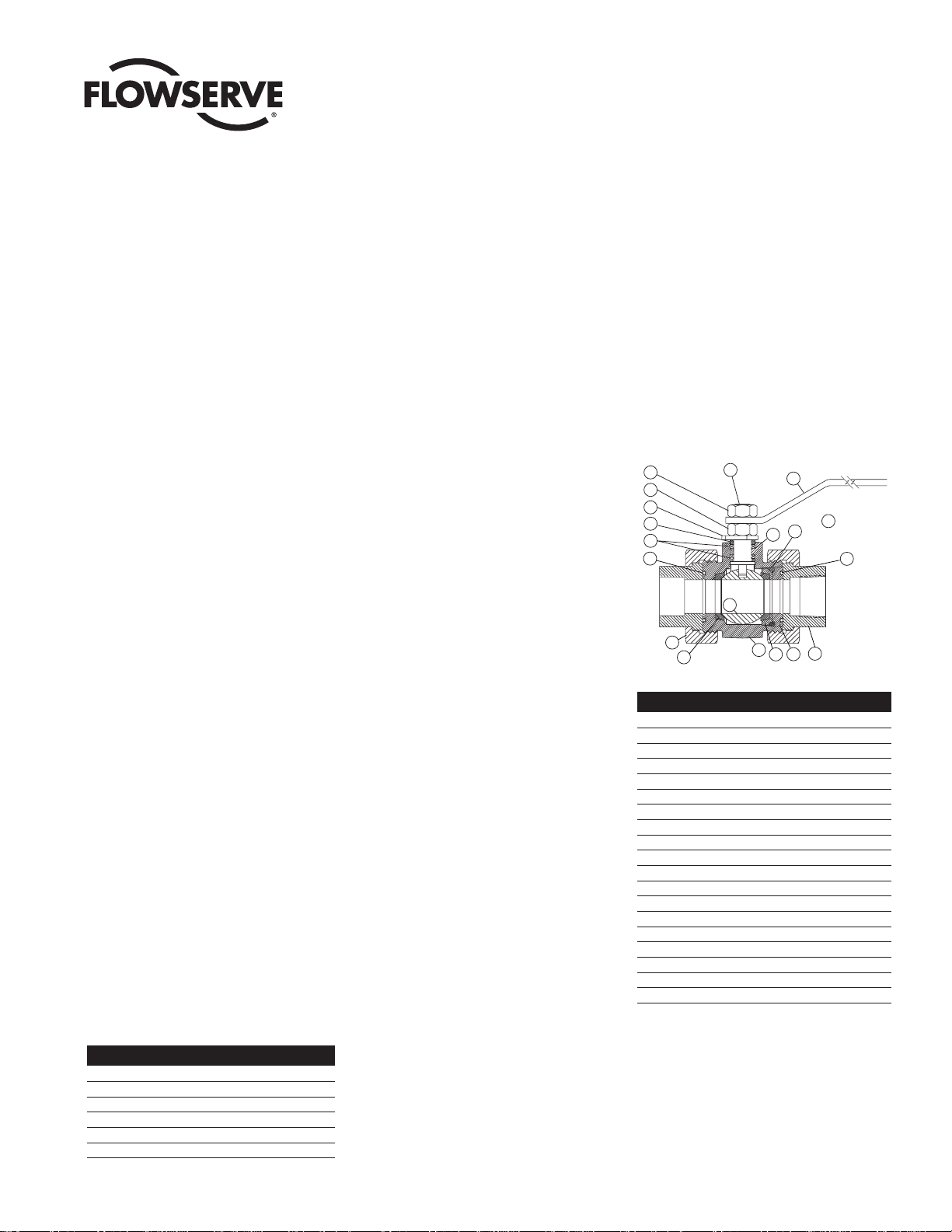
Figure 1
McCANNA/MARPAC Valves
MMAIM2002
(Part IM005)
Petro Double Union End Ball Valve
Model E790: 1/
4" – 2" Size
Installation, Operation and Maintenance Instructions
No. Description
1 Handle
2 Stem
3 Stop Pin (not shown)
4 Handle Retainer Nut
5Travel Stop (1" thru 2" sizes only)
6 Gland Ring
7 Threaded Spacer
8 Seat Socket
9 Ball
10 Seat (2)
11 Body Seal
12 Union Nut (2)
13 Union End (2)
14 Body
15 End Seal
16 Spacer Seal
17 Stem Seal
18 Adjusting Nut
19 Grounding Washer
Valve Size Hex Size (Across Flats)
1
/
4",
3
/
8",
1
/
2"
5
/
8"
3
/
4
"
13
/
16
"
1" 1"
11/
4"1
1
/
4"
11/
2
"1
1
/
2
"
2" 111/
16"
down through the body and out the open
end of the body (14). Remove the upper
and lower stem seals (17) and the
grounding washer (19). Grounding washer (19) is not used with the FIRE-GARD
valves. Save the grounding washer (19)
for reassembly.
Figure 2
1. Installation
These valves may be installed in any position
utilizing standard pipe fitting practices. With
the ends installed, the body can be rotated
before tightening the union nuts.
Welding Ends (Socket Weld)
To keep from destroying soft parts, loosen
and slide away union nuts (12). Remove
valve from line, taking care that the end and
body seals (15 & 16) are not damaged, and
then weld socket ends in position.
NOTE: Prior to removing valve from line,
valve may be tack welded in line for line-up
purposes.
The base material of valve covered by this
procedure conforms to the following:
• Carbon Steel - ASTM A105 (Forged)
• 316 Stainless Steel - ASTM A182
GRF316 (Forged)
Before welding, push pipe snugly into union
ends and then back off approximately
1
/
16
".
The socket and at least one inch of the pipe
(at the joint) must be free of all foreign material which might prove detrimental to the weld.
Use the smallest electrode and minimum
amperage consistent with efficient welding to
minimize warpage. Tacks should be ground
out before completing the root pass in that
area. Weld stringer beads with no weaving
and stagger all starts and stops.
Carbon steel ends should be allowed to cool
slowly. The valve ends may be covered with a
heat resisting blanket to promote slow cooling.
2. Stem Seal Adjustment
If leakage is evident in stem packing area,
tighten the adjusting nut (18)
1
/
8 turn. If leak
still persists, repeat above. Replacement of
the stem seal (17) is indicated if the leak is
still apparent after
1
/
2 turn.
3. Seal Replacement
There must be no line pressure on the valve
at this time and ball should be partially open.
A. Loosen union nuts (12) and slide nuts out
of the way. Now the valve body (14) can
be removed from the line for servicing.
B. Remove end seal (15) and body seal
(11). This may be done with a sharp
instrument, such as a pocket knife. Care
should be taken to avoid damage to the
surfaces of the seal groove.
C. Remove threaded spacer (7) by using
“allen” type wrench or hexagonal bar.
(See Figure 1.)
D. To take out spacer seal (16), seat socket
(8), one seat (10) and the ball (9) –
rotate stem (2) so ball (9) is in fully
closed position and insert wooden dowel
(not metal) in port opposite threaded end
and tap gently on ball (9) thereby forcing
it out of body (14).
NOTE: Extreme caution should be taken
to avoid damage to the ball (9).
E. Take out other seat (10).
F. Remove the handle retainer nut (4), han-
dle (1), adjusting nut (18), travel stop (5)
(part of the handle on sizes
1
/
2" and
3
/
4")
and the gland ring (6). Push the stem (2)
4
18
5
6
17
11
12
10
2
9
1
NOT
SHOWN
3
16
19
15
14
13
7
8
Page 2

Flowserve recommends replacement of
all soft parts whenever the valve is disassembled for reconditioning. Replacement
parts can be ordered in kit form.
4. Reassembly
A. Put one seat (10) in body (14).
NOTE: Seats (10) are to be installed
with concave surfaces positioned
against the ball.
CAUTION: The high-pressure valve
Model E790K is a uni-directional (oneway) valve and it is extremely
important that the unslotted
downstream seat and the slotted
upstream seat be positioned properly.
The unslotted downstream seat is placed
in the solid end of the body and the slotted upstream seat is placed in the spacer
end of the body.
B. Lightly grease the stem seals (17) and
the seal area and threads of the stem (2).
Insert stem seal(s) (17) into the lower
stem seal cavity with the raised outer
edge facing into the counterbore. (The
1
/
4"
thru
1
/
2" size and all sizes of the FIRE-
GARD seals are square cut seals.) Insert
stem (2) through the installed stem seals
(17) and the body (14). Place the travel
stop (5) on the stem (2) so that it rests
on the top surface of the body (14).
Thread the adjusting nut (18) on the
stem (2) and torque to
3
/
4 of the final
torque value for the adjusting nut (18).
Remove the adjusting nut (18) and the
travel stop (5) without moving the stem
(2). Place the grounding washer (19) into
the upper seal cavity with the raised fingers pointing up. Push the upper stem
seal(s) (17) into the counterbore with
raised outer edge pointing into the valve.
Add the gland ring (6), the travel stop (5)
and the adjusting nut (18). Make sure the
travel stop (5) is installed so that the
valve can close in a clockwise direction
and open counterclockwise. If the rotation is not correct, the travel stop (5)
must be inverted. Torque the adjusting
nut (18) to the value shown in Figure 3.
Cycle several times and check the stem
nut torque.
C. Turn the stem (2) to a position with the
stem tang flats inside the body parallel
to the cavity. (Ball will be in the closed
position and stay in this position through
steps D, E, F and G.)
D. Install the ball (9). NOTE: Ball should be
carefully examined for nicks, scratches,
pitting or corrosion and replaced as
necessary.
E. Put other seat (10) into seat socket (8)
and fit up against shoulder in body (14).
(See note in paragraph 4A.)
F. Install spacer seal (16).
G. Install threaded spacer (7) using appro-
priate allen type wrench or hexagonal
bar. (See Figure 1 on page 1).
NOTE: In order to achieve proper seat
preload against ball, threaded spacer (7)
must come to a complete stop when
screwed into body (14).
H. Press body seal (11) and end seal (15)
and threaded spacer (7) into grooves on
face of body and threaded spacer.
I. Place body (14) back into line position
and tighten union nuts (12).
J. Install travel stop (5), if required (see
Figure 2), handle (1) and handle retainer
nut (4).
5. Testing
Prior to placing valve back into line position
test as follows:
A. Place the closed valve in a vise with the
pipe run in the vertical position and connect air pressure to lower port.
Introduce 50 to 100 psig air. Pour water
into upper port to cover the ball and
visually check for bubbles. If bubbles
appear, pour the water out, cycle the
valve several times and recheck. To
check for leakage in the other port,
reverse the valve and introduce air pressure to the port just checked.
B. In the event of stem seal leakage, adjust
as described in Section 2 “Stem Seal
Adjustment.”
Flow Control Division
McCANNA/MARPAC Valves
Flowserve Corporation has established industry leadership in the design and manufacture of its products. When properly selected, this Flowserve product is designed to perform its intended function
safely during its useful life. However, the purchaser or user of Flowserve products should be aware that Flowserve products might be used in numerous applications under a wide variety of industrial
service conditions. Although Flowserve can (and often does) provide general guidelines, it cannot provide specific data and warnings for all possible applications. The purchaser/user must therefore
assume the ultimate responsibility for the proper sizing and selection, installation, operation, and maintenance of Flowserve products. The purchaser/user should read and understand the Installation
Operation Maintenance (IOM) instructions included with the product, and train its employees and contractors in the safe use of Flowserve products in connection with the specific application.
While the information and specifications contained in this literature are believed to be accurate, they are supplied for informative purposes only and should not be considered certified or as a guarantee of
satisfactory results by reliance thereon. Nothing contained herein is to be construed as a warranty or guarantee, express or implied, regarding any matter with respect to this product. Because Flowserve
is continually improving and upgrading its product design, the specifications, dimensions and information contained herein are subject to change without notice. Should any question arise concerning
these provisions, the purchaser/user should contact Flowserve Corporation at any one of its worldwide operations or offices.
For more information about Flowserve Corporation, contact www.flowserve.com or call USA 1-800-225-6989.
FLOWSERVE CORPORATION
FLOW CONTROL DIVISION
1978 Foreman Drive
Cookeville, Tennessee 38501 USA
Phone: 931 432 4021
Facsimile: 931 432 3105
www.flowserve.com
© 2003 Flowserve Corporation, Irving, Texas, USA. Flowserve and Worcester Controls are registered trademarks of Flowserve Corporation. MMAIM2002 (Part IM005)
Stem Nut
Torques (lb-ft) Number of Seals
SIZE TORQUE UPPER LOWER
1
/
2"5 11
3
/
4" to 2" 10 1 2
NOTICE: McCANNA Valves are designed and manufactured using good workmanship and materials, and they meet all applicable industry standards. Flowserve Corporation is anxious to avoid
injuries and property damage which could result from misapplication of the product. Proper valve selection is imperative. Examples of the misapplications or misuse of a valve include but are not
limited to use in a service in which the pressure/temperature rating is exceeded or in a chemical service incompatible with the valve materials; use of undersized valve actuators; use of extremely
fast valve actuation and/or continuous valve cycling on standard valves; making modifications of the product of any kind; failure to use caution in operating valves in high temperature, high pressure, or highly hazardous services; and the failure to maintain valves as recommended. The right is reserved to change or modify product design or construction without prior notice and without
incurring any obligation to make such changes and modification on products previously or subsequently sold.
Figure 3
Printed in USA 11/03
 Loading...