

Page 1

Durametallic® Double CRO
Dual single coil spring friction
drive for applications with
water lubrication properties
Installation
Instructions
Experience In Motion
Page 2
1 Equipment Check
1.1 Follow plant safety regulations:
• lock out motor and valves.
• wear designated personal safety equipment.
• relieve any pressure in system.
• consult plant MSDS les for hazardous material regulations.
1.2 Adjust the bearings, coupling, and impeller so that the shaft is
in its operating axial position. Disassemble equipment to allow
access to seal installation area.
1.3 Remove all burrs and sharp edges from the shaft, sleeve, seal
housing bore and face, keyways, and any other feature that may
contact sealing gaskets. Replace worn components. Clean all
piping plans.
1.4 Check requirements for shaft, sleeve, and seal housing.
See Figure 1.
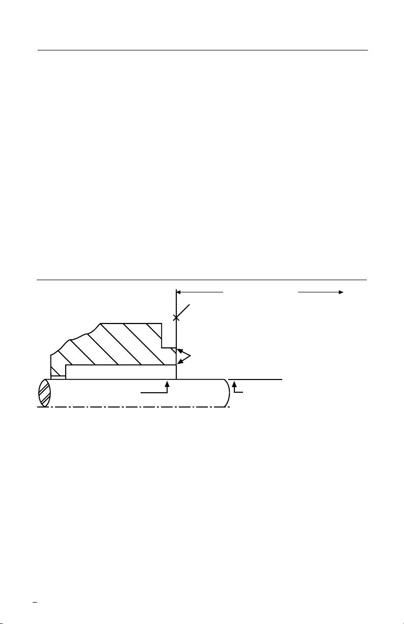
Seal Chamber Requirements Figure 1
To first obstruction
Face of seal housing to be square to the
axis of the shaft to within 0.0005 mm/mm
(0.0005 inch/inch) of seal chamber bore TIR
and have a 1.6 μm (63 μinch) R finish or better
a
Gland pilot can be at either of these
register locations, concentric to within
0.125 mm (0.005 inch) of shaft or
Seal housing bore to have 3.2 μm
(125 μinch) R finish or better
Sleeve or shaft finish to be
0.8 μm (32 μinch) R or better
• Bearings must be in good condition
• Maximum lateral or axial movement of shaft (end play) = 0.25 mm (0.010 inch) TIR
• Maximum shaft runout at face of seal housing = 0.05 mm (0.002 inch) TIR
• Maximum dynamic shaft deflection at seal housing = 0.05 mm (0.002 inch) TIR
a
a
sleeve OD TIR
Shaft or sleeve OD
+0.000 mm (+0.000 inch)
-0.050 mm (-0.002 inch)
+0.000 mm (+0.000 inch) API 610/682
-0.025 mm (-0.001 inch) DIN/ISO
ANSI
1.5 Check assembly drawing included with the Double CRO seal for
specic seal design, materials of construction, dimensions, and
piping connections.
1.6 Check shaft or sleeve OD, box depth, box bore, and distance
to the rst obstruction to ensure that they are dimensionally the
same as shown on the seal assembly drawing.
The images of parts shown in these instructions may differ visually from the actual
parts due to manufacturing processes that do not affect the part function or quality.
2
Page 3

1.7 Check gland pilot and bolt holes to ensure they are adaptable
to the equipment and are the same as shown on the assembly
drawing.
1.8 Handle all seal parts with care, they are manufactured to precise
tolerances. The seal faces; rotating face and stationary face, are
of special importance. These two sealing faces are lapped at to
within three light bands (34.8 millionths of an inch).
Keep the seal faces perfectly clean at all times.
1.9 Do not use oil or silicone lubricant on the shaft or sleeve of this
friction driven seal. Use water or a mild water soluble soap solution
to ease installation.
2 Installation on Single End Suction Vertical Split Case
and Vertical In-Line Pumps (1 seal chamber)
2.1 Lubricate one of the two stationary face seat gasket O-rings
with water or mild water soluble soap solution and nest this O-ring
in the gland cavity. Press the stationary face into the gland
with the sealing face orientated toward the inboard side of the
gland. Use hand pressure only. Position the gland over the shaft
or sleeve with the sealing face orientated toward the seal chamber
(stufng box). Place the gland as close to the bearing bracket as
possible. Do not bump the stationary face against the shaft as it
may chip, crack, or break.
2.2 Lubricate the shaft or sleeve with water or soap solution.
2.3 Install the rotating seal parts on the shaft or sleeve one piece
at a time:
• Outer rotating face with rotating face gasket O-ring.
• Single coil spring.
• Inner rotating face with rotating face gasket O-ring.
The rotating seal parts should be as close to their nal axial position as
possible with the rotating face sealing surfaces facing away from the
spring and toward the stationary face sealing surfaces.
2.4 Lubricate the seal chamber bore with water or soap solution.
The seal chamber is usually the stufng box contained in the
pump back plate.
3
Page 4

2.5 Lubricate the other stationary face seat gasket O-ring with
water or soap solution and place this O-ring on the back shoulder
of the remaining stationary face. Slide the inner stationary face
with the O-ring into position at the bottom of the chamber.
2.6 Wipe the seal faces clean with alcohol. Seal faces should not be
lubricated but should be left clean and dry.
Caution: Consult material safety data sheets for proper handling
of alcohol.
2.7 Install the seal chamber (pump back-plate) and assemble
the pump. Position the gland to the face of the seal housing.
Be sure the gland pilot is properly engaged. Tighten the gland
stud nuts evenly, cross stagger the adjustment of the nuts.
Follow the equipment manufacturer’s recommendation for gland
stud nut torque. In the absence of recommendations, gland stud
nuts should only be torqued to establish a leak tight seal at the
gland gasket. Proper land bolt adjustment is especially important
with clamp style inserts where torque may damage the insert.
In this case, gland stud nuts should be torqued to a maximum
of 13.5 N-m (10 ft-lbs).
2.8 See section 4, Operational Recommendations, before starting
pump.
3 Double Suction and Multistage Horizontal Split Case
Pumps (2 seal chambers)
Note: The parting gasket between the upper and lower sections of
the pump casing must be ush with the seal chamber bore and face
or leakage will occur past the O-rings and gaskets.
3.1 Lubricate the shaft or sleeve and the seal chamber bore with
water or a mild water soluble soap solution.
3.2 Lubricate one stationary face seat gasket O-ring with water
or soap solution and place this O-ring on the back shoulder of the
inner stationary face. Slide the stationary face with the O-ring into
position at the bottom of the chamber. Do not bump the stationary
face against the shaft as it may chip, crack, or break.
4
Page 5

3.3 Install the rotating seal parts on the shaft or sleeve one piece
at a time:
• Inner rotating face with rotating face gasket O-ring.
• Single coil spring.
• Outer rotating face with rotating face gasket O-ring.
3.4 Wipe the seal faces clean with alcohol. Seal faces should not be
lubricated but should be left clean and dry. Position the rotating
seal parts as close to their nal axial position as possible with
the inner rotating face sealing surface in contact with the inner
stationary sealing face.
Caution: Consult material safety data sheets for proper handling
of alcohol.
3.5 Lubricate the remaining stationary face seat gasket O-ring with
water or soap solution and nest this O-ring in the gland cavity.
Press the stationary face into the gland with the stationary
sealing face orientated toward the inboard side of the gland. Use
hand pressure only. Wipe the sealing face clean with alcohol.
3.6 Position the gland over the shaft or sleeve with the stationary
face oriented toward the seal chamber (stufng box). Do not
bump the stationary face against the shaft as it may chip, crack,
or break. With the gland and/or stationary face pilot properly
engaged, tighten the gland stud nuts up evenly, cross staggering
the adjustment of the nuts. The gland nuts should be torqued to a
maximum of 13 N-m (10 ft-lbs). Excessive gland nut pressure can
result in distortion of the stationary face. Adjust the bearings,
coupling, and impeller so that the shaft is in its operating
axial position. The rotating seal parts will automatically position
themselves, subsequent axial adjustment of the shaft does not
require resetting of the seal.
3.7 See section 4, Operational Recommendations, before starting
pump.
5
Page 6

4 Operational Recommendations
4.1 Do not start up the equipment dry. Vent air from the casing of
the pump and the seal chamber before startup.
4.2 If soap was used to ease seal installation, ush the seal chamber
with water before startup to prevent rotating face gasket O-ring
slippage and subsequent loss of seal drive.
4.3 Adjust the barrier water ow rate so there is no more than a
11°C (20°F) temperature rise between inlet and outlet temperature.
The barrier outlet water temperature should never exceed 51°C
(120°F). Consult Flowserve if you have any questions.
4.4 If the seal runs hot, above 51°C (120°F) or squeals, shut down the
pump immediately as not to damage the seal. Check to see if the
barrier water supply is working properly. If barrier water system is
working correctly, check the seal housing dimension to ensure the
seal is not over-compressed due to axial dimensional stack up
problems.
For special problems encountered during installation, contact your
nearest Flowserve Sales and Service Representative or Authorized
Distributor.
Suggested Barrier Water Supply System - Plan 53A Figure 2
outlet
seal
end view
inlet
6
pressure source,
normally open
liquid ll
normally closed
Reservoir
cooling out
pressure indicator (low)
pressure switch (high)
level switch (high)
level indicator
level switch (low)
cooling coils
cooling in
drain, normally closed
Page 7

5 Repairs
This product is a precision sealing device. The design and dimension
tolerances are critical to seal performance. Only parts supplied by
Flowserve should be used to repair the seal. These parts are available
from numerous Flowserve stocking locations. To order replacement
parts, refer to the part code number and B/M number. A spare backup
seal should be stocked to reduce repair time. The following partscan also
be stocked for emergency needs.
Rotating Faces Spring
Rotating Face Gasket O-rings Gland Gaskets
Stationary Faces Stationary Face Seat Gasket O-rings
gland
gasket
gland
seat gasket
O-ring
stationary
face
rotating
face
rotating
face
gasket
O-ring
coil spring
When repairs are not conducted at the customer's location,
decontaminate the seal assembly and return it to Flowserve, with
an order marked "Repair or Replace". A signed certicate of
decontamination must be attached. A Material Safety Data Sheet
(MSDS) must be enclosed for any product that came in contact with
the seal. The seal assembly will be inspected and, if repairable, it will be
rebuilt, tested, and returned in its original condition.
7
Page 8

TO REORDER REFER TO
flowserve.com
B/M #
F.O
.
FIS133eng 10/13 Printed in USA
To find your local Flowserve representative
and find out more about Flowserve Corporation,
visit www.flowserve.com
Flowserve Corporation has established industry leadership in the design and manufacture of its products. When
properly selected, this Flowserve product is designed to perform its intended function safely during its useful life.
However, the purchaser or user of Flowserve products should be aware that Flowserve products might be used
in numerous applications under a wide variety of industrial service conditions. Although Flowserve can provide
general guidelines, it cannot provide specific data and warnings for all possible applications. The purchaser/user
must therefore assume the ultimate responsibility for the proper sizing and selection, installation, operation, and
maintenance of Flowserve products. The purchaser/user should read and understand the Installation Instructions
included with the product, and train its employees and contractors in the safe use of Flowserve products in connection
with the specific application.
While the information and specifications contained in this literature are believed to be accurate, they are supplied for
informative purposes only and should not be considered certified or as a guarantee of satisfactory results by reliance
thereon. Nothing contained herein is to be construed as a warranty or guarantee, express or implied, regarding any
matter with respect to this product. Because Flowserve is continually improving and upgrading its product design,
the specifications, dimensions and information contained herein are subject to change without notice. Should any
question arise concerning these provisions, the purchaser/user should contact Flowserve Corporation at any one of
its worldwide operations or offices.
© 2013 Flowserve Corporation
USA and Canada
Kalamazoo, Michigan USA
Telephone: 1 269 381 2650
Telefax: 1 269 382 8726
Europe, Middle East, Africa
Roosendaal, the Netherlands
Telephone: 31 165 581400
Telefax: 31 165 554590
Asia Pacific
Singapore
Telephone: 65 6544 6800
Telefax: 65 6214 0541
Latin America
Mexico City
Telephone: 52 55 5567 7170
Telefax: 52 55 5567 4224
 Loading...