

Page 1
Dual Gas Barrier Seals
Experience In Motion
GB-200, GF-200, GX-200,
and BufferPac
Installation
Instructions
Page 2
1 Equipment Check
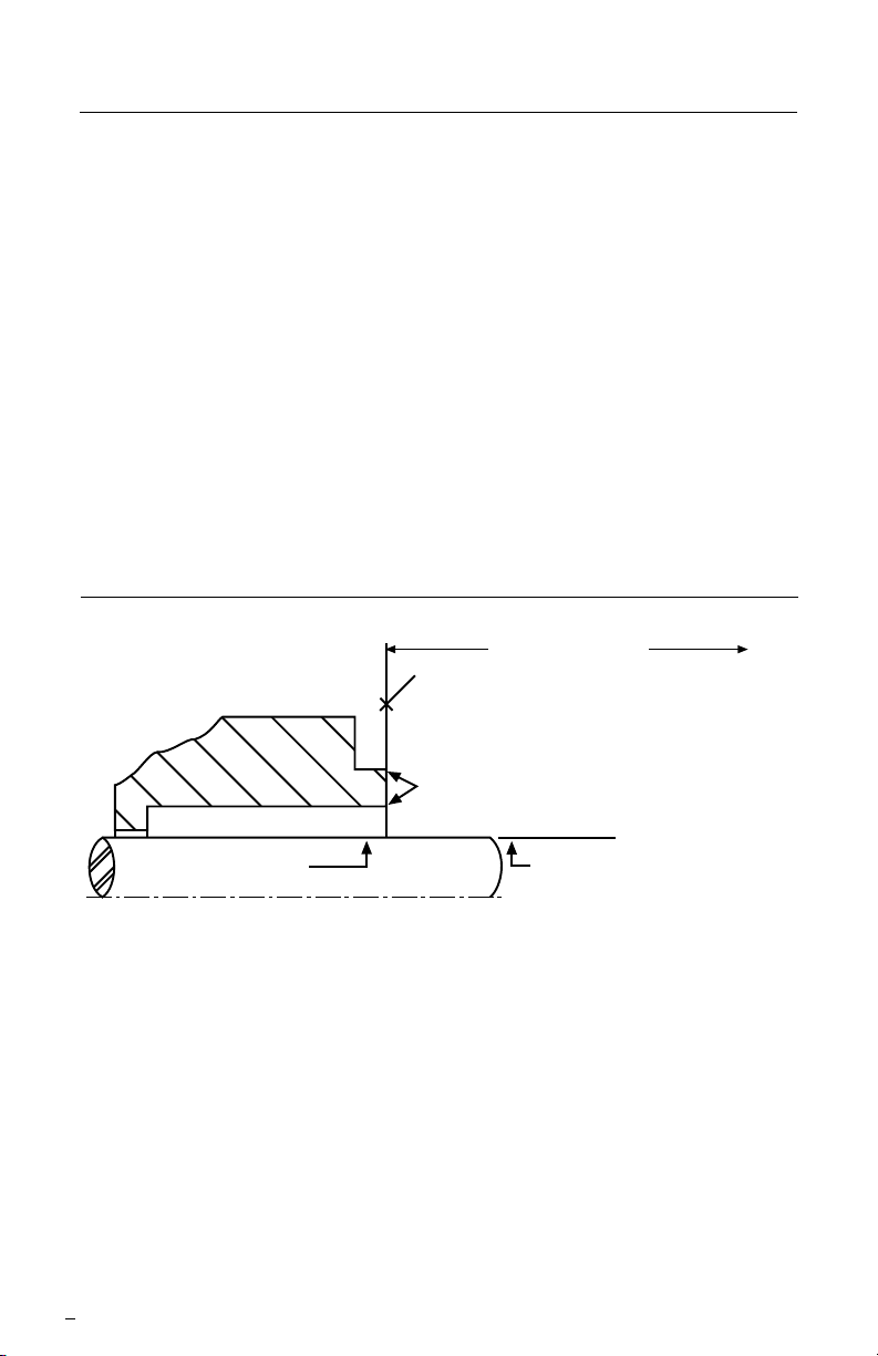
To first obstruction
Face of seal housing to be square to the axis
of the shaft to within 0.013 mm per millimeter
(0.0005 inches) of seal chamber bore FIM and
have a √1.6
μm (63 μinch) R finish or better
a
Gland pilot can be at either of these
register locations, concentric to within
0.13 mm (0.005 inch) FIM of shaft or sleeve OD
Seal housing bore to have √3.2 μm
(125 μinch) R finish or better
Sleeve or shaft finish to be
0.8 μm (32 μinch) R or better
a
a
Shaft or sleeve OD
+0.000 mm (+0.000 inch)
-0.050 mm (-0.002 inch) ANSI
+0.000 mm (+0.000 inch) API 610/682
-0.025 mm (- 0.001 inch) DIN/ISO
• Bearings must be in good condition
• Maximum lateral or axial movement of shaft (end play) = 0.25 mm (0.010 inch) FIM
• Maximum shaft runout at face of seal housing = 0.05 mm (0.002 inch) FIM
• Maximum dynamic shaft deflection at seal housing = 0.05 mm (0.002 inch) FIM
1.1 Follow plant safety regulations prior to equipment disassembly:
• Lock out motor and valves.
• Wear designated personal safety equipment.
• Relieve any pressure in the system.
• Consult plant MSDS les for hazardous material regulations.
1.2 Disassemble equipment in accordance with equipment manufac-
turer's instructions to allow access to seal installation area.
1.3 Remove existing mechanical seal and gland or compression
packing and packing gland (follower ange).
1.4 Check seal chamber to ensure that it is the appropriate design
for the seal you are installing. Dual gas seal congurations are
designed for both standard bore and enlarged bore seal chambers.
Seal Chamber Requirements Figure 1
1.5 Make sure the shaft or sleeve and the seal chamber face
are clean and free of burrs, cuts, dents, or corrosion that might
cause leakage past the sleeve packing or housing O-ring gasket.
Replace worn shaft or sleeve. Remove sharp edges from
keyways and threads.
2
The images of parts shown in these instructions may differ visually from the actual
parts due to manufacturing processes that do not affect the part function or quality.
Page 3
1.6 Check equipment dimensions. They must agree with the
dimensions shown in Figure 1 and the assembly drawing
supplied with the seal. Critical dimensions include shaft or
sleeve OD and the minimum distance to the rst obstruction.
1.7 Check gland bolting to ensure that bolt diameter and bolt
circle conform to the dimensions shown in the assembly drawing.
1.8 Check seal chamber stud length to ensure that they conform
to the dimensions shown in the assembly drawing. Assembly may
require longer studs or use of bolts or cap screws if existing studs
are not long enough.
1.9 Check rotation direction of the equipment. Uni-directional seal
designs must be operated only in the direction shown on the
seal gland.
1.10 Handle the seal with care, it is manufactured to precise
tolerances. The sealing faces of the rotors and stators are
specially nished. Keep the seal faces perfectly clean at all
times. Oil, silicone lubrication, or type of grease should not be
applied to these seal faces.
2 Dual Gas Barrier Seal Installation
Tools needed:
Provided
• Krytox* lubricant for
sleeve O-rings
Not provided
• Open end wrench for
gland nuts
• Allen wrenches for
setting devices and set
screws
• Allen wrenches for
gland cap screws if they
are required in place of
gland nuts or bolts
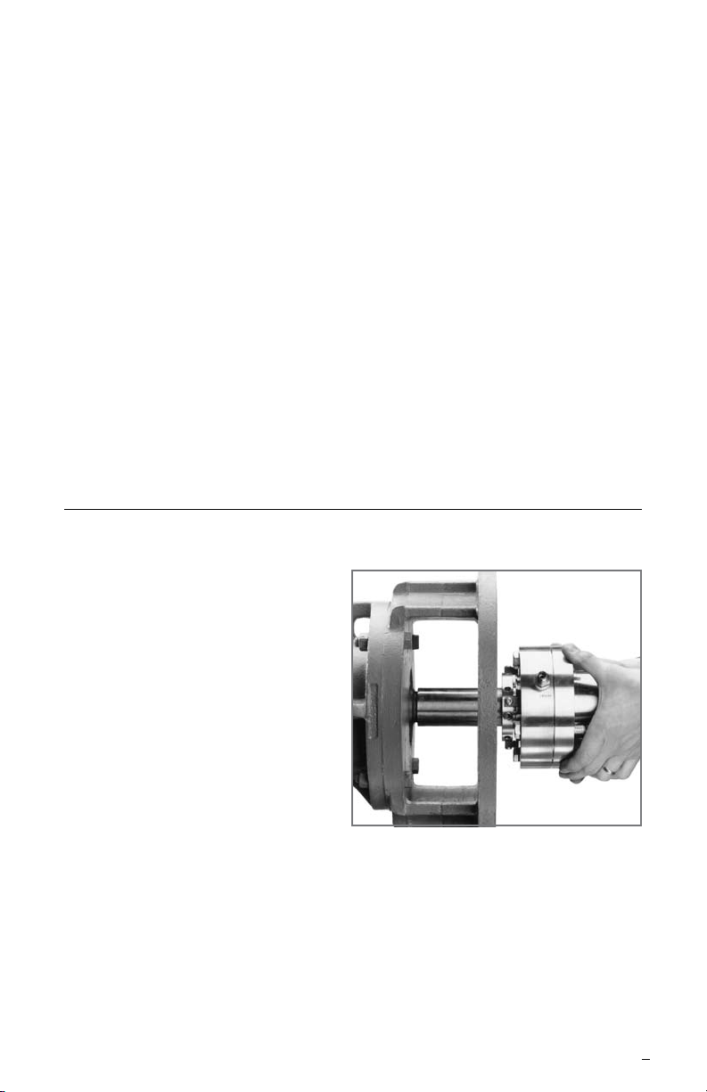
2.1 Lubricate the shaft or sleeve OD lightly with Krytox lubricant
provided. If bolts or cap screws are required in place of the seal
chamber studs, insert them through the gland bolt holes before
sliding the assembly onto the shaft. Slide the complete seal
cartridge onto the shaft, Figure 2, with the end with the setting
devices toward the bearing housing.
Note: Check for rotation direction requirements on the seal gland or
assembly drawing before continuing.
*Krytox a Registered Trademark of E.I.DuPont
Install Seal Cartridge Figure 2
3
Page 4

2.1.1 Optional: TARSEx Bushing
A
B
A
B
Installation
• Slide seal assembly
against the bearing frame.
Install TARSEx Bushing (optional)
Figure 3
gland
• Clean lubrication off pump
shaft.
• Install the friction drive
TARSEx bushing with
O-ring, positioning them
against the retaining
plate with the bushing
grooves oriented toward
the seal. See Figure 3.
retaining plate bushing
O-ring
2.2 Install the pump seal chamber, Figure 4. Postion the seal gland
gas barrier inlet, port A shown in Figure 5, in the 9:00 o’clock
position and the plugged gas barrier outlet, port B in the 6:00
o’clock position for normal installations. Alternate positioning of the
gland may be necessary with
some pumps, where the bearing housing interferes with
Install pump seal chamber
Figure 4
piping. Bolt the seal cham-
ber in place on the bearing
housing.
Note: Either port can be used for
gas barrier inlet or outlet.
2.3 Assemble the pump, adjust
the bearings, set the impeller, connect pump piping.
Allow no pipe strain on the
pump casing. Connect the
coupling so that the shaft is in its operating axial position.
Position gland inlet Figure
Normal Installation Alternate Installation
Gas
Barrier
Inlet
Port
Gas Barrier
Outlet Port
4
Gas Barrier
Outlet Port
Gas
Barrier
Inlet
Port
Page 5

2.4 Position the seal with housing O-ring gasket in place against the
seal chamber face and tighten the gland nuts evenly in a diagonal
sequence. Do not over tighten the gland nuts.
2.5 Using a cross-tightening method tighten the set screws on the
seal cartridge drive collar, Figure 6.
Tighten drive collar set screws
Figure 6
2.6 Remove setting devices by removing the screws with an Allen
wrench, Figure 7. Save the setting devices and screws for future
use in either removing the seal from service or to reset the pump
impeller, see section 5.
2.7 Turn the shaft by hand to ensure free operation.
2.8 Pipe up the gland connections to the seal, see section 3.
2.9 See Operational Recommendations, section 4, before
starting pump.
Remove setting devices
Figure 7
3 Piping
The Dual Gas Barrier Seal is designed to be operated in a normally dry
running mode with a pressurized clean inert gas (nitrogen) or air between
the two seals.
The gland is equipped with a gas barrier inlet and outlet connection.
3.1 Vent out the gas barrier line prior to connecting to the seal gland
to ensure that foreign material has not collected in the piping.
5
Page 6

3.2 Connect gas barrier Plan 74 shown in Figure 8 to the gas
seal
end view
barrier inlet port (refer to Figure 5). The pressure gage and
regulator are required to set the barrier gas pressure 2 to 4 bar
(25 to 50 psig) higher than that of the product being sealed
(seal chamber pressure).
Note: It is important that the pressure gage and the low pressure alarm
be installed close to the gas barrier inlet port for accurate values.
An optional control panel that incorporates all the equipment in a Plan 74
for a Dual Gas Barrier Seal is available from Flowserve.
3.3 Plug the gas barrier outlet port, (refer to Figure 5), or connect to a
block valve.
Plan 74 for Dual Gas Barrier Seal Figure 8
gas
barrier
inlet
gas barrier outlet
1 - gas barrier outlet, normally closed
2 - gas barrier inlet, normally open
3 - filter drain, normally closed
F
G
2
1
3
E
D
A
B
C
A - coalescing filter
B - regulator
C - flow indicator
D - flow switch (high)
E - pressure switch (low)
F - pressure indicator
G - check valve
6
Page 7

4 Operation
To assure reliable, long-life operation of your Dual Gas Barrier Seal,
the following guidelines should be observed.
4.1 Do not exceed corrosion limits. Your Flowserve seal is designed
to resist corrosion by most chemicals. However, do not expose
the seal materials of construction to products outside of their
corrosion limits. The seal assembly drawing lists the materials of
construction. Consult Flowserve for chemical resistance ratings.
4.2 Do not exceed the pressure limits of the seal design. Do not let
the barrier gas pressure fall below 2 bar (25 psi) above the seal
chamber pressure.
4.3 Do not exceed the maximum temperature limits of the seal
design.
4.4 Do not operate at speeds lower than the seal's minimum speed,
if applicable.
4.4.1 On startup and shutdown, the seal's speed should be
transitioned between stationary and the seal's minimum
speed as quickly as possible.
4.5 For uni-directional designs, do not turn the shaft opposite to the
direction arrow indicated on the gland.
4.6 Observe the start-up. The seal barrier cavity must be pressur-
ized before pump start-up and at all times during pump operation.
For best performance, do not cavitate or run the pump dry. Open
valves to ood pump with product uid before start-up. Maintain
the seal barrier gas pressure even when the pump is not running.
5 Reset pump impeller
To reset the pump impeller, follow plant safety procedures, etc., see 1.1.
• Reinstall the setting devices.
• Loosen the cartridge drive collar set screws.
• Adjust the impeller clearance following pump manufacturer’s
instructions.
• Tighten the set screws on the cartridge drive collar.
• Remove the setting devices. Save the setting devices and
screws.
• Perform steps 2.7 to 2.9.
7
Page 8

TO REORDER REFER TO
flowserve.com
USA and Canada
Kalamazoo, Michigan USA
Telephone: 1 269 381 2650
Telefax: 1 269 382 8726
Europe, Middle East, Africa
Roosendaal, the Netherlands
Telephone: 31 165 581400
Telefax: 31 165 554590
Asia Pacific
Singapore
Telephone: 65 6544 6800
Telefax: 65 6214 0541
Latin America
Mexico City
Telephone: 52 55 5567 7170
Telefax: 52 55 5567 4224
B/M #
F.O
.
6 Repair
This product is a precision sealing device. The design and dimension
tolerances are critical to seal performance. Only parts supplied by
Flowserve should be used to repair a seal. To order replacement parts,
refer to the part code and B/M number. A spare backup seal should be
stocked to reduce repair time.
When seals are returned to Flowserve for repair, decontaminate the
seal assembly and include an order marked "Repair or Replace."
A signed certicate of decontamination must be attached.
A Material Safety Data Sheet (MSDS) must be enclosed for any
product that came in contact with the seal. The seal assembly will be
inspected and, if repairable, it will be rebuilt, tested, and returned.
FIS108eng REV 09/12 Printed in USA
To find your local Flowserve representative
and find out more about Flowserve Corporation,
visit www.flowserve.com
Flowserve Corporation has established industry leadership in the design and manufacture of its products. When
properly selected, this Flowserve product is designed to perform its intended function safely during its useful life.
However, the purchaser or user of Flowserve products should be aware that Flowserve products might be used
in numerous applications under a wide variety of industrial service conditions. Although Flowserve can provide
general guidelines, it cannot provide specific data and warnings for all possible applications. The purchaser/user
must therefore assume the ultimate responsibility for the proper sizing and selection, installation, operation, and
maintenance of Flowserve products. The purchaser/user should read and understand the Installation Instructions
included with the product, and train its employees and contractors in the safe use of Flowser ve products in connection
with the specific application.
While the information and specifications contained in this literature are believed to be accurate, they are supplied for
informative purposes only and should not be considered certified or as a guarantee of satisfactory results by reliance
thereon. Nothing contained herein is to be construed as a warranty or guarantee, express or implied, regarding any
matter with respect to this product. Because Flowserve is continually improving and upgrading its product design,
the specifications, dimensions and information contained herein are subject to change without notice. Should any
question arise concerning these provisions, the purchaser/user should contact Flowserve Corporation at any one of
its worldwide operations or offices.
© 2012 Flowserve Corporation
 Loading...