

Page 1

FCD WCAIM2058-01
(Part 60130)
Worcester Actuation Systems
DataFlo Digital Electronic Remote Controller DRC-17
Installation, Operation and Maintenance Instructions
MODELS:
10 – For DataFlo Remote Controller and 10-23 75 Actuators
25 – For DataFlo Remote Controller and 25/30 75 Actuators
Setpoint Inputs:
DRC17-1K 1000 ohm Resistance Setpoint Input
DRC17-13 135 ohm Resistance Setpoint Input
DRC17-1 1 to 5 milliamp Setpoint Input
DRC17-4 4 to 20 milliamp Setpoint Input
DRC17-10 10 to 50 milliamp Setpoint Input
DRC17-5V 0 to 5 VDC Setpoint Input
DRC17-XV 0 to 10 VDC Setpoint Input
Voltages:
120A – 120 VAC Power Circuits
240A – 240 VAC Power Circuits
Page 2

2 DataFlo Digital Electronic Remote Controller DRC17 WCAIM2058
Flow Control
Worcester Actuation Systems
TABLE OF CONTENTS
1.0 GENERAL 3
1.1 Important Items . . . . . . . . . . . . . . . . . . . . . . . . . . . . . . . . . . . . . . . . . . . . . . . . . . . . . . . . . . . . . . . . . . . . . . . . . . . . . . . . . . . . . . . . . . . . . . . . . . . . . .3
1.2 Operating Temperature . . . . . . . . . . . . . . . . . . . . . . . . . . . . . . . . . . . . . . . . . . . . . . . . . . . . . . . . . . . . . . . . . . . . . . . . . . . . . . . . . . . . . . . . . . . . . . . . .4
1.3 Operating Humidity . . . . . . . . . . . . . . . . . . . . . . . . . . . . . . . . . . . . . . . . . . . . . . . . . . . . . . . . . . . . . . . . . . . . . . . . . . . . . . . . . . . . . . . . . . . . . . . . . . . .4
2.0 FIELD INSTALLATION OF MOTOR DRIVER BOARD INTO SERIES 75 ACTUATOR 4
2.1 General . . . . . . . . . . . . . . . . . . . . . . . . . . . . . . . . . . . . . . . . . . . . . . . . . . . . . . . . . . . . . . . . . . . . . . . . . . . . . . . . . . . . . . . . . . . . . . . . . . . . . . . . . . . . . .4
2.2 Mounting Potentiometer . . . . . . . . . . . . . . . . . . . . . . . . . . . . . . . . . . . . . . . . . . . . . . . . . . . . . . . . . . . . . . . . . . . . . . . . . . . . . . . . . . . . . . . . . . . . . . . .4
2.3 Mounting Circuit Board . . . . . . . . . . . . . . . . . . . . . . . . . . . . . . . . . . . . . . . . . . . . . . . . . . . . . . . . . . . . . . . . . . . . . . . . . . . . . . . . . . . . . . . . . . . . . . . . .5
3.0 WIRING OF THE DIGITAL CONTROLLER 7
3.1 Wiring the DRC Motor Driver Board . . . . . . . . . . . . . . . . . . . . . . . . . . . . . . . . . . . . . . . . . . . . . . . . . . . . . . . . . . . . . . . . . . . . . . . . . . . . . . . . . . . . . .11
3.2 Wiring From the DRC to the Actuator . . . . . . . . . . . . . . . . . . . . . . . . . . . . . . . . . . . . . . . . . . . . . . . . . . . . . . . . . . . . . . . . . . . . . . . . . . . . . . . . . . . . .11
3.3 Wiring the DRC Power Supply Board . . . . . . . . . . . . . . . . . . . . . . . . . . . . . . . . . . . . . . . . . . . . . . . . . . . . . . . . . . . . . . . . . . . . . . . . . . . . . . . . . . . . .11
3.3.1 Wiring for a Current Setpoint . . . . . . . . . . . . . . . . . . . . . . . . . . . . . . . . . . . . . . . . . . . . . . . . . . . . . . . . . . . . . . . . . . . . . . . . . . . . . . . . . . . . . . .11
3.3.2 Wiring for a Potentiometer Setpoint . . . . . . . . . . . . . . . . . . . . . . . . . . . . . . . . . . . . . . . . . . . . . . . . . . . . . . . . . . . . . . . . . . . . . . . . . . . . . . . . . .12
3.3.3 Wiring for an Analog Current Process . . . . . . . . . . . . . . . . . . . . . . . . . . . . . . . . . . . . . . . . . . . . . . . . . . . . . . . . . . . . . . . . . . . . . . . . . . . . . . . .12
3.3.4 Wiring for an RTD Process . . . . . . . . . . . . . . . . . . . . . . . . . . . . . . . . . . . . . . . . . . . . . . . . . . . . . . . . . . . . . . . . . . . . . . . . . . . . . . . . . . . . . . . . .12
3.3.5 Wiring for a Thermocouple Process . . . . . . . . . . . . . . . . . . . . . . . . . . . . . . . . . . . . . . . . . . . . . . . . . . . . . . . . . . . . . . . . . . . . . . . . . . . . . . . . . .12
3.3.6 Serial Communications Wiring . . . . . . . . . . . . . . . . . . . . . . . . . . . . . . . . . . . . . . . . . . . . . . . . . . . . . . . . . . . . . . . . . . . . . . . . . . . . . . . . . . . . . .13
3.3.7 Alarm Output Wiring . . . . . . . . . . . . . . . . . . . . . . . . . . . . . . . . . . . . . . . . . . . . . . . . . . . . . . . . . . . . . . . . . . . . . . . . . . . . . . . . . . . . . . . . . . . . . .13
3.3.8 Position/Control Select Wiring . . . . . . . . . . . . . . . . . . . . . . . . . . . . . . . . . . . . . . . . . . . . . . . . . . . . . . . . . . . . . . . . . . . . . . . . . . . . . . . . . . . . . .13
3.3.9 Position Feedback Output Wiring . . . . . . . . . . . . . . . . . . . . . . . . . . . . . . . . . . . . . . . . . . . . . . . . . . . . . . . . . . . . . . . . . . . . . . . . . . . . . . . . . . . .14
3.3.10 Utility Voltage Source . . . . . . . . . . . . . . . . . . . . . . . . . . . . . . . . . . . . . . . . . . . . . . . . . . . . . . . . . . . . . . . . . . . . . . . . . . . . . . . . . . . . . . . . . . .14
3.3.11 Spare Connection Locations . . . . . . . . . . . . . . . . . . . . . . . . . . . . . . . . . . . . . . . . . . . . . . . . . . . . . . . . . . . . . . . . . . . . . . . . . . . . . . . . . . . . . .14
4.0 OPERATION OF THE REMOTE CONTROLLER 14
4.1 General Operation . . . . . . . . . . . . . . . . . . . . . . . . . . . . . . . . . . . . . . . . . . . . . . . . . . . . . . . . . . . . . . . . . . . . . . . . . . . . . . . . . . . . . . . . . . . . . . . . . . . .14
4.2 The DRC Keypad . . . . . . . . . . . . . . . . . . . . . . . . . . . . . . . . . . . . . . . . . . . . . . . . . . . . . . . . . . . . . . . . . . . . . . . . . . . . . . . . . . . . . . . . . . . . . . . . . . . . .14
4.3 Changing Modes . . . . . . . . . . . . . . . . . . . . . . . . . . . . . . . . . . . . . . . . . . . . . . . . . . . . . . . . . . . . . . . . . . . . . . . . . . . . . . . . . . . . . . . . . . . . . . . . . . . . .15
4.4 Tuning the Controller . . . . . . . . . . . . . . . . . . . . . . . . . . . . . . . . . . . . . . . . . . . . . . . . . . . . . . . . . . . . . . . . . . . . . . . . . . . . . . . . . . . . . . . . . . . . . . . . . .15
4.5 The Run Mode . . . . . . . . . . . . . . . . . . . . . . . . . . . . . . . . . . . . . . . . . . . . . . . . . . . . . . . . . . . . . . . . . . . . . . . . . . . . . . . . . . . . . . . . . . . . . . . . . . . . . . .15
4.5.1 The DRC Display . . . . . . . . . . . . . . . . . . . . . . . . . . . . . . . . . . . . . . . . . . . . . . . . . . . . . . . . . . . . . . . . . . . . . . . . . . . . . . . . . . . . . . . . . . . . . . . . .15
4.5.2 Alarms . . . . . . . . . . . . . . . . . . . . . . . . . . . . . . . . . . . . . . . . . . . . . . . . . . . . . . . . . . . . . . . . . . . . . . . . . . . . . . . . . . . . . . . . . . . . . . . . . . . . . . . .15
4.6 Program Mode . . . . . . . . . . . . . . . . . . . . . . . . . . . . . . . . . . . . . . . . . . . . . . . . . . . . . . . . . . . . . . . . . . . . . . . . . . . . . . . . . . . . . . . . . . . . . . . . . . . . . . .16
4.6.1 Entering the Program Mode . . . . . . . . . . . . . . . . . . . . . . . . . . . . . . . . . . . . . . . . . . . . . . . . . . . . . . . . . . . . . . . . . . . . . . . . . . . . . . . . . . . . . . . .16
4.6.2 Examining and Changing Parameter Values . . . . . . . . . . . . . . . . . . . . . . . . . . . . . . . . . . . . . . . . . . . . . . . . . . . . . . . . . . . . . . . . . . . . . . . . . . . .16
4.6.3 Setting Default Factory Parameter Values . . . . . . . . . . . . . . . . . . . . . . . . . . . . . . . . . . . . . . . . . . . . . . . . . . . . . . . . . . . . . . . . . . . . . . . . . . . . . .18
4.6.4 DRC Programmable Parameter Definitions . . . . . . . . . . . . . . . . . . . . . . . . . . . . . . . . . . . . . . . . . . . . . . . . . . . . . . . . . . . . . . . . . . . . . . . . . . .19
4.7 Manual Setpoint Mode . . . . . . . . . . . . . . . . . . . . . . . . . . . . . . . . . . . . . . . . . . . . . . . . . . . . . . . . . . . . . . . . . . . . . . . . . . . . . . . . . . . . . . . . . . . . . . . . .20
4.7.1 Entering the Manual Setpoint Mode . . . . . . . . . . . . . . . . . . . . . . . . . . . . . . . . . . . . . . . . . . . . . . . . . . . . . . . . . . . . . . . . . . . . . . . . . . . . . . . . . .20
4.7.2 Enabling, Disabling, and Changing the Setpoint . . . . . . . . . . . . . . . . . . . . . . . . . . . . . . . . . . . . . . . . . . . . . . . . . . . . . . . . . . . . . . . . . . . . . . . . .20
4.8 Manual Position Mode . . . . . . . . . . . . . . . . . . . . . . . . . . . . . . . . . . . . . . . . . . . . . . . . . . . . . . . . . . . . . . . . . . . . . . . . . . . . . . . . . . . . . . . . . . . . . . . . .21
4.8.1 Entering the Manual Position Mode . . . . . . . . . . . . . . . . . . . . . . . . . . . . . . . . . . . . . . . . . . . . . . . . . . . . . . . . . . . . . . . . . . . . . . . . . . . . . . . . . .21
4.8.2 Changing Valve Position . . . . . . . . . . . . . . . . . . . . . . . . . . . . . . . . . . . . . . . . . . . . . . . . . . . . . . . . . . . . . . . . . . . . . . . . . . . . . . . . . . . . . . . . . . .21
4.8.3 Auto-Tune . . . . . . . . . . . . . . . . . . . . . . . . . . . . . . . . . . . . . . . . . . . . . . . . . . . . . . . . . . . . . . . . . . . . . . . . . . . . . . . . . . . . . . . . . . . . . . . . . . . . . .21
4.8.3.1 Starting Auto-Tune . . . . . . . . . . . . . . . . . . . . . . . . . . . . . . . . . . . . . . . . . . . . . . . . . . . . . . . . . . . . . . . . . . . . . . . . . . . . . . . . . . . . . .21
4.8.3.2 The Automated Auto-Tune Procedure and Results . . . . . . . . . . . . . . . . . . . . . . . . . . . . . . . . . . . . . . . . . . . . . . . . . . . . . . . . . . . . . .21
4.9 Calibration Mode . . . . . . . . . . . . . . . . . . . . . . . . . . . . . . . . . . . . . . . . . . . . . . . . . . . . . . . . . . . . . . . . . . . . . . . . . . . . . . . . . . . . . . . . . . . . . . . . . . . . .22
4.9.1 Entering the Calibration Mode . . . . . . . . . . . . . . . . . . . . . . . . . . . . . . . . . . . . . . . . . . . . . . . . . . . . . . . . . . . . . . . . . . . . . . . . . . . . . . . . . . . . . .22
4.9.2 Calibration of Valve Position . . . . . . . . . . . . . . . . . . . . . . . . . . . . . . . . . . . . . . . . . . . . . . . . . . . . . . . . . . . . . . . . . . . . . . . . . . . . . . . . . . . . . . . .22
4.9.3 Calibration of Cycle Time . . . . . . . . . . . . . . . . . . . . . . . . . . . . . . . . . . . . . . . . . . . . . . . . . . . . . . . . . . . . . . . . . . . . . . . . . . . . . . . . . . . . . . . . . .23
4.9.4 Calibration of 4-20 mA Setpoint Input . . . . . . . . . . . . . . . . . . . . . . . . . . . . . . . . . . . . . . . . . . . . . . . . . . . . . . . . . . . . . . . . . . . . . . . . . . . . . . . .23
4.9.5 Calibration of a Potentiometer Setpoint Input . . . . . . . . . . . . . . . . . . . . . . . . . . . . . . . . . . . . . . . . . . . . . . . . . . . . . . . . . . . . . . . . . . . . . . . . . . .23
4.9.6 Calibration of an Analog (4-20 mA) Process Input . . . . . . . . . . . . . . . . . . . . . . . . . . . . . . . . . . . . . . . . . . . . . . . . . . . . . . . . . . . . . . . . . . . . . . .23
4.9.7 Calibration of an RTD Process Input . . . . . . . . . . . . . . . . . . . . . . . . . . . . . . . . . . . . . . . . . . . . . . . . . . . . . . . . . . . . . . . . . . . . . . . . . . . . . . . . . .24
4.9.8 Calibration of a Thermocouple Process Input . . . . . . . . . . . . . . . . . . . . . . . . . . . . . . . . . . . . . . . . . . . . . . . . . . . . . . . . . . . . . . . . . . . . . . . . . . .24
5.0 TECHNICAL DATA 25
6.0 TROUBLESHOOTING 26
Page 3

1.0 General
The Worcester Actuation Systems Dataflo Remote Controller (DRC17)
was designed for use with the Worcester Series 75 electric actuators.
However, it may also be used with other actuators or electrically
operated rotary devices, provided the specified load parameters given
in Part 5.5 are not exceeded.
1.1 Important Items
PLEASE READ THIS SECTION
1.1.1 Sensitivity to Electrical Noise
The Dataflo Remote Controller (hereafter referred to as
the DRC) is sensitive to electrical noise on signal, process
and power supply lines. The DRC can also be affected by
radiated electrical noise. For maximum controller
sensitivity, the electrical noise level should be as low as
possible. Follow the installation and calibration guidelines
carefully and use shielded cable as noted in the paragraph
below.
Shielded wire should be used for all setpoint and process
signal input circuit wiring regardless of length. The
wiring from the feedback potentiometer and the control
signals between the actuator and the DRC enclosure
should be in a shielded cable as shown in section 3.0. If
multiple cables are used, their individual shields must be
attached together inside the actuator and connected as
shown for the one shield. A shield should never be used
as one of the signal wires. Shields for setpoint and
process signals should be grounded at their source and
not connected at the DRC.
NOTE: ALL WIRING TO TERMINAL STRIPS SHOULD BE
INSERTED ONLY TO MID-POINT OF TERMINAL STRIP.
For 240 VAC DRC only, limit switches do not directly
control the motor(s). Therefore, the actuator will not stop
when the limit switches trip. Use care not to drive the
actuator past its normal limits.
1.1.2 Fuses and Input Currents
The Setpoint input circuit is protected with a fuse (F1)
located on the microcontroller board inside the DRC
enclosure. The fuse is used to protect the input circuit
from excessively high current. The fuse is a ¹⁄₁₆ Amp
(about 62 mA) fast-acting fuse (Littlefuse PICO II or
equivalent). Although this fuse limits excessively high
currents, care should be taken to prevent current values
that are less than 62 mA but above 20 mA. High current
that would not cause the fuse to open might cause
excessive heating of the sense resistor. This fuse is
mounted in a socket holder for easy replacement.
The power supply circuit is protected with a fuse (F1)
located on the DRC Power Supply Board. This fuse is ¹⁄₄
Amp slow-acting fuse used to protect the power supply
from excessive current. If this fuse opens, the DRC
should be returned to Flowserve for service.
If the Analog Process Module is used, it also contains a
fuse for protection. The fuse (F1) is the same as that
described for the Setpoint circuit and is located on the
Analog Process Module. Although this fuse limits
excessively high currents, care should be taken to prevent
current values that are less than 62 mA but above 20 mA.
High current that would not cause the fuse to open might
cause excessive heating of the sense resistor. This fuse is
mounted in a socket holder for easy replacement.
1.1.3 Valve Actuator Configurations
The DRC electronics are designed to control the valve
actuator in 90° quadrants only, however with alternate
feedback potentiometer gearing, 180° of rotation is also
available. The number of quadrants over which the board
will control is determined by the number of teeth on the
feedback potentiometer pinion gear.
Quadrants of Operation
1.1.4 Position Feedback Potentiometer Calibration
Quite often, units received for repair are totally functional
except the feedback potentiometer (pot) is out of
calibration. It is very important that the feedback pot be
properly calibrated for correct operation of the DRC. It is
also very important that the actuator shaft not be rotated
out of the quadrant for which the feedback pot has been
calibrated. Always check the feedback pot calibration first
if calibration problems are encountered. See paragraph
6.5.6 in the troubleshooting section.
WCAIM2058 DataFlo Digital Electronic Remote Controller DRC17 3
Flow Control
Worcester Actuation Systems
Page 4

4 DataFlo Digital Electronic Remote Controller DRC17 WCAIM2058
1.1.5 Storage Conditions
Flowserve recommends that all products that must be
stored prior to installation be stored indoors, in an
environment suitable for human occupancy. Do not store
product in areas where exposure to relative humidity
above 85%, acid or alkali fumes, radiation above normal
background, ultraviolet light, or temperatures above
120°F or below 40°F may occur. Do not store within 50
feet of any source of ozone.
Temperature and humidity are the two most important
factors that determine the usefulness and life of electronic
equipment.
1.2 Operating Temperature
Operating solid state electronic equipment near or beyond its
high-temperature rating is the primary cause for most failures. It
is very important to be aware of and take into consideration
factors that affect the temperature at which the electronic circuits
will operate.
Operating an electronic device at or below its low-temperature
rating generally results in a unit operating poorly or not at all,
but it will usually resume normal operation as soon as rated
operating temperatures are reached. Low-temperature problems
can be easily cured by addition of a thermostatically controlled
heater to the actuator housing.
The DRC is rated for operation between –40°F (with heater and
thermostat) and 160°F. The Worcester Series 75 actuator and the
DRC enclosure both require a maximum ambient temperature of
115°F to insure the circuit boards maximum temperature of
160°F is not exceeded.
Temperature Ranging allows the user to specify the actual
process temperature conditions within the stipulated range of the
measuring element, i.e., RTD or thermocouple. The control range
can be as little as 50°C or 100°C respectively, or to the full range
of the measuring device. For temperatures above 600°C, consult
factory.
1.3 Operating Humidity
Most electronic equipment has a reasonable degree of inherent
humidity protection and additional protection is supplied by the
manufacturer in the form of moisture proofing and fungicidal
coatings.
Such protection, and the 3 to 4 watts of heat generated by the
circuit board assemblies will generally suffice for environments
where the average relative humidity is in the area of 80% or less
and ambient temperatures are in the order of 70°F average.
Where relative humidity is consistently 80% to 90% and the
ambient temperature is subject to large variations, consideration
should be given to installing a heater and thermostat option in
the enclosures. The heater should not increase the enclosure
temperature to the point where a circuit board assembly’s
temperature exceeds 160°F.
In those instances where the internal heater would bring a circuit
board’s operating temperature near or above its maximum rating, the
user might consider purging the enclosures with a cool, dry gas. The
initial costs can usually be paid off quickly in the form of greatly
extended equipment life, low maintenance needs, and much less
process downtime.
2.0 Field Installation of Motor Driver
Board into Series 75 Actuator
2.1 General
If the DRC was purchased with the Motor Driver Board factory
installed, proceed to section 3.0.
2.1.1 Parts Listing
Qty Name
1 Circuit Board Subassembly
1 Insulating Board
4 Washer (Nylon)
4 Grommets (Rubber)
4 Mounting Screws (Circuit Board)
1 Nameplate – Base
1 Wiring Label – Cover
5 Cable Ties
1 Closed End Splice
1 Wire – White
1 Potentiometer Kit Subassembly
1 Bracket – Right (Long) (10-23 sizes only)
1 Bracket – Left (Short) (10-23 sizes only)
2 Spacer (Bracket) (10-2 sizes only)
2 Mounting Screws (Bracket/Spacer)
(10-23 sizes only)
1 Mounting Bracket (25-30 sizes only)
2 Mounting Screw (Bracket) (25-30 sizes only)
2.1.2 Tools Needed
¹⁄₄" Nut Driver, ¹⁄₈" screwdriver, needle nose pliers, ¹⁄₁₆"
Allen wrench (cams and spur gear).
2.1.3 Operation Check of Basic Actuator
Set cams for about 1° to 3° of over travel in each
direction (full-open and full-closed). That is, for 0° to 90°
operation set at minus 3° and plus 93°. Power terminals
1 and 3 for CCW rotation, terminals 1 and 4 for CW
rotation (reference part 6.2).
Flow Control
Worcester Actuation Systems
Page 5

WCAIM2058 DataFlo Digital Electronic Remote Controller DRC17 5
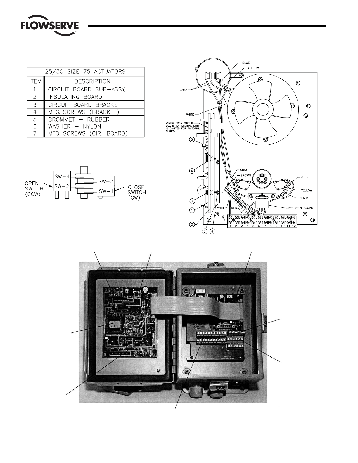
2.2 Mounting Potentiometer:
2.2.1 Mounting Single Potentiometer into Series 75 Actuator
(See Figure 1.)
A. With the potentiometer mounted to the potentiometer
bracket and the spur gear loosely fitted to the
potentiometer shaft, mount the potentiometer bracket
(if not already mounted) as follows:
10-23 75 Actuator: Remove the motor module
mounting screws on the side of the module furthest
away from the actuator shaft. Position potentiometer
assembly bracket holes over screw holes and line up
potentiometer shaft with center of actuator shaft,
replace and tighten screws.
25/30 75 Actuator: Attach potentiometer bracket to
motor support plate between the terminal strip and
actuator shaft with mounting screws as shown in
Figure 1.
2.2.2 Mounting Optional Dual Potentiometer Into Series 75
Electric Actuator
A dual potentiometer is also available when external
resistance indication is also desired. A dual pot consists
of an “A” & “B” pot. The “A” pot is at the front, closest to
the bracket. The “B” pot is at the rear, away from the
bracket. Each pot can serve only one function.
Note: Voltage limit of “B” pot is 30 volts maximum.
Mount potentiometer per paragraph A of 2.2.1.
2.2.3 Potentiometer Wiring
Connect the single or “A” potentiometer leads to the
terminal strip per wiring diagram. For dual pot, “B” pot
must be wired directly to external device.
2.2.4 Adjusting Potentiometer
A. Reference part 6.1 for moving the actuator shaft
electrically.
B. 10-30 75 Actuator
Place the large face gear (12) over the actuator shaft
with the gear teeth down and secure with snap ring
(16) provided.
NOTE: The face gear utilizes a friction fit to the shaft.
For best results, wipe off any lubricant that may be on
the shaft before sliding on the face gear.
CAUTION: Do not overstretch the snap ring; use the
minimum opening to allow it to slip over the gear.
C. Adjust the potentiometer spur gear until there is
approximately ¹⁄₁₆" engagement with the large face
gear. Ensure there is minimum backlash between the
gears. Tighten the spur gear set screw.
D. Rotate the face gear back and forth to ensure smooth
and easy operation of the potentiometer.
E. IMPORTANT: For 90° Valves:
See paragraph 4.9.2 for feedback potentiometer
calibration procedure.
F. The feedback potentiometer is now adjusted for use
in the 75 actuator. Add the potentiometer caution
label to the outside of the actuator cover.
CAUTION: If the actuator shaft is manually rotated a
multiple of 360° from its original position, the
feedback potentiometer will no longer be in
calibration. It must be recalibrated per paragraph
4.9.2, in order for the DRC to operate properly.
2.2.5 IMPORTANT
The feedback potentiometer is calibrated for only one 90
degree quadrant of valve operation.
If the valve and actuator output shaft is repositioned to
another 90 degree quadrant the feedback potentiometer
must be recalibrated as per paragraph 2.2.4.
The Series 75 actuators offer a manual override feature.
Whenever repositioning the valve using this manual
override capability on these actuators, move the valve
only within the 90 degrees for which the feedback
potentiometer has been calibrated.
2.3 Mounting Circuit Board
2.3.1 For 120/240 VAC 10-23 Size Electric Actuators
(See Figure 2.)
A. Mount the brackets to the actuator motors or spacers
as provided. The longer bracket is mounted to the
right side of the actuator (when facing the terminal
strip using the motor mounting screws).
B. Remove and replace motor screws carefully to avoid
stripping the threads of these self-tapping screws.
C. Once these motor screws and brackets are firmly
secured, firmly tap the motor stator to force
realignment of the top motor bearing.
D. Loosen all actuator terminal strip screws necessary to
connect the circuit board’s wiring to the terminal strip.
See manual section 3.0 for proper wiring of circuit
board to the actuator’s terminal strip. Wire routing is
important. Ensure that the wiring is not pinched and is
not near cams or mechanical brake (if installed).
E. Assemble circuit board into actuator. Slide rubber
grommets onto insulating board. Put nylon washer
under heads of self-tapping screws. (Four screws will
be used to install the circuit board onto the brackets).
F. Place circuit board over brackets. See Figure 2.
Loosely fasten board to brackets using mounting
screws.
G. The circuit board is wired to the terminal strip as
shown in section 3.0.
H. Snug down the circuit board and secure mounting
screws such that grommets are about half
compressed.
Flow Control
Worcester Actuation Systems
Page 6

6 DataFlo Digital Electronic Remote Controller DRC17 WCAIM2058
Flow Control
Worcester Actuation Systems
10-23 75
Plan View
25/30 75
Plan View
View A-A
View B-B
Figure 1
Item Description
1 LIMIT SWITCHES
2 MOTOR MODULE
3 MOTOR MODULE MOUNTING SCREWS (2)
4 TERMINAL STRIP
5 ACTUATOR SHAFT
6 POTENTIOMETER
7 POTENTIOMETER BRACKET
8 SPUR GEAR
9 SPUR GEAR SET SCREW
10 POTENTIOMETER LEADS
Item Description
11 POTENTIOMETER SHAFT
12 FACE GEAR
13 POTENTIOMETER BRACKET
14 MOUNTING SCREWS
15 MOTOR SUPPORT PLATE
16 SNAP RING
17 LOCKWASHERS (2)
18 NUT
NOTE: ILLUSTRATIONS SHOW SINGLE POTENTIOMETER ONLY.
Page 7

WCAIM2058 DataFlo Digital Electronic Remote Controller DRC17 7
2.3.2 For 120/240 VAC 25 and 30 Size Electric Actuators:
(See Figure 3.)
A. Assemble circuit board to bracket as shown.
B. Place four rubber grommets onto the insulating
board. Put nylon washers on the self-tapping screws
and place screws through the circuit board and
insulating board. Start screws into the bracket.
C. If no insulating board is used, place a rubber
grommet between the board and the bracket. Tighten
all screws such that the grommets are about half
compressed.
D. Use two screws to fasten circuit board bracket to the
motor mounting plate (component side of the board
is facing out).
E. The circuit board is wired to the terminal strip as
shown in Section 3.0.
NOTE: Standard wiring for switches and capacitor as
shown in Figure 3 is the same for 10-23 75 actuators
and is for 120 VAC DRC only. For 240 VAC DRC, see
part 3.1.
2.3.3 Installation of Optional 4-20 Position Output Module
(if used and not factory installed)
A. The output of the position output option is suited for
a 4-20 mA DC meter with 0-100% scale (such as
General Electric type GE185) which is not part of the
package. If properly calibrated, it indicates actuator
shaft position from closed (0°, 0% to open (90°,
100%).
B. The module plugs into the upper left corner of the
Microcontroller Board located in the DRC enclosure.
Align pin 1 (soldered shut) on the module with the
lower right socket on the Microcontroller Board.
3.0 Wiring of the Digital Controller
The DRC consists of three circuit boards: 1) A motor driver board
inside the actuator housing; 2) A power supply board inside the DRC
enclosure; and 3) A microcontroller board inside the DRC enclosure.
The microcontroller board is prewired and installed to the cover of the
DRC enclosure. This wiring procedure discusses wiring for the motor
driver and power supply boards only.
Figure 4 shows the inside of the DRC enclosure. The following wiring
diagrams refer to connectors located inside the DRC enclosure and
the 75 actuator. The DRC enclosure connectors are located as
indicated in Figure 4.
For factory-installed motor driver board, wiring between board,
terminal strip and switches, and for feedback potentiometer has been
done.
Grounding wires should be connected to green colored grounding
screw (if present) on actuator base or to any baseplate mounting
screw in the actuator.
Minimum Fuse Ratings
See table below for minimum fuse rating when overcurrent protection
is used in motor power circuit.
Minimum Fuse Rating for Overcurrent Protection
Actuator Size Voltage Fuse Rating
10-23 120 VAC 5 A
25/30 120 VAC 10 A
10-23 240 VAC 3 A
25/30 240 VAC 5 A
NOTE: This table shows the minimum rating to prevent inrush current
from blowing the fuse.
Flow Control
Worcester Actuation Systems
Figure 2
Page 8
8 DataFlo Digital Electronic Remote Controller DRC17 WCAIM2058
Flow Control
Worcester Actuation Systems
Limit Switch Locations
(SW-3 and SW-4 are optional.)
Figure 3
Figure 4
Location for
optional position
feedback module
Microcontroller
Board
Power Supply
Board
Process
Module
Alarm
LED
TB1
Top and bottom tiers are
connected together
P1
TB2
Page 9
WCAIM2058 DataFlo Digital Electronic Remote Controller DRC17 9
Flow Control
Worcester Actuation Systems
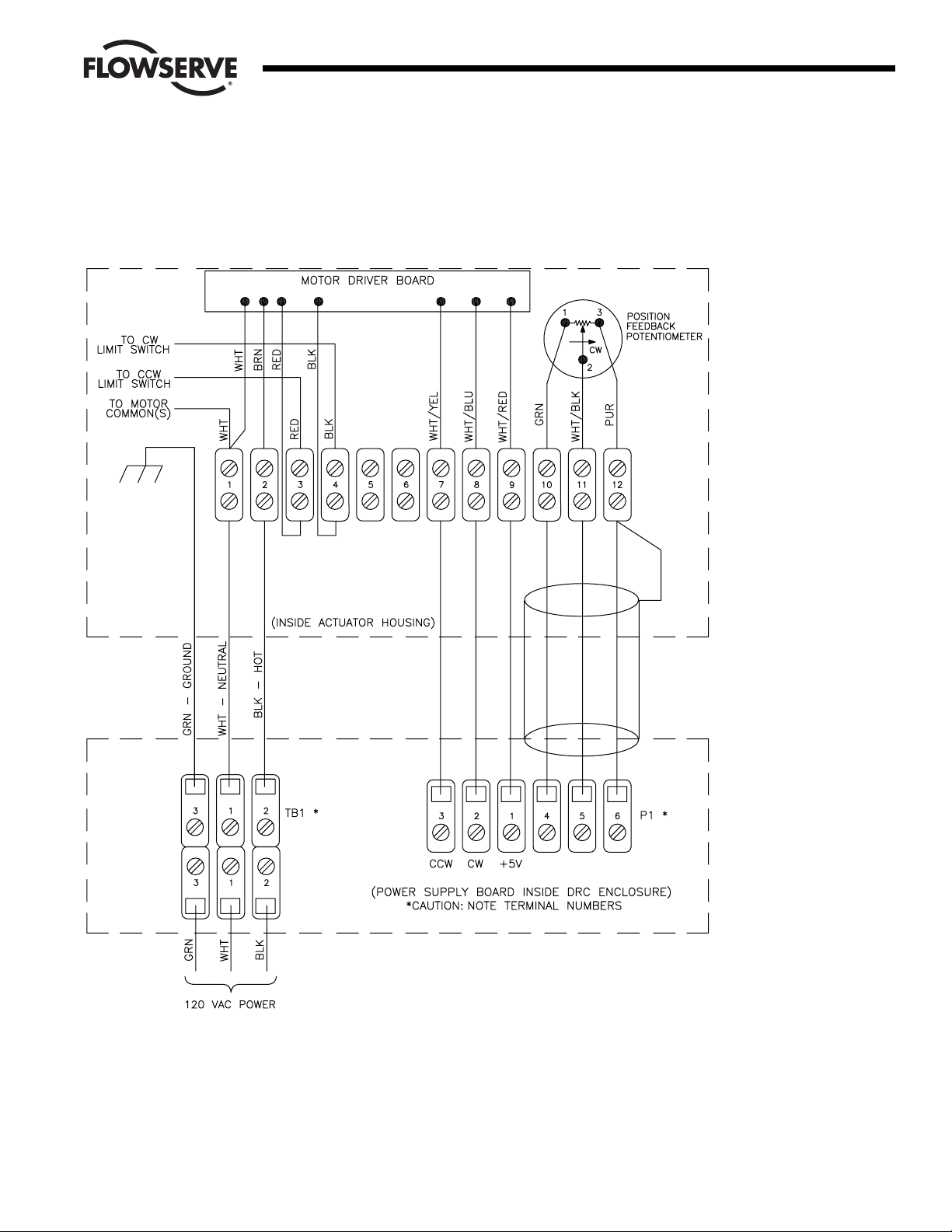
Power and Control Signal Wiring
120 VAC Models
Figure 5
Page 10

10 DataFlo Digital Electronic Remote Controller DRC17 WCAIM2058
Flow Control
Worcester Actuation Systems
Power and Control Signal Wiring
240 VAC Models
Figure 6
Page 11

WCAIM2058 DataFlo Digital Electronic Remote Controller DRC17 11
3.1 Wiring the DRC Motor Driver Board
In the following instructions, the “rear” side of the terminal strip
refers to the side that faces toward the center of the actuator; the
“front” side faces toward the outside of the actuator. Wire color
descriptions show the dominant color first and the stripe last
(e.g., WHT/YEL is a white wire with yellow stripe).
If not factory-installed, locate the motor driver board and mount
the board to the actuator brackets inside the actuator housing
per part 2.3.
Insert the WHITE wire from the board along with the WHITE motor
common wire to the rear side of location 1 on the terminal strip.
NOTE: When there are multiple wires going to terminal location
1, use short white wire provided. Connect it to terminal location
1 and then splice it to the other white wires (common) using the
closed-end splice provided.
Attach the BROWN wire to the rear side of location 2 on the
terminal strip.
Attach the RED wire to the front side of location 3 on the
terminal strip. The RED wire from the rear of this terminal should
go to the counterclockwise limit switch.
Attach the BLACK wire to the front side of location 4 on the
terminal strip. The BLACK wire from the rear of this terminal
should go to the clockwise limit switch.
For 120 VAC only, remove the yellow wire from terminal 5 and
the brown wire from terminal 6, disconnect them from the N.O.
contacts of switches 1 and 2 and discard them.
NOTE: For 240 VAC Controller Wiring:
For this voltage only, the two limit switches do not directly
switch off the motor.
Replace the original gray and blue actuator wires (make a note of
which color wire is on which capacitor terminal and then discard
them) with those provided. Connect them to the capacitor as
originally wired and to terminals 3 and 4 (gray to 3, blue to 4)
(reference 240 VAC wiring diagram).
The two black wires (#20 gauge) from the motor driver board
connect to the common and normally closed contacts of switch
1 (lower right hand switch), and the two red wires (#20 gauge)
from the motor driver board connect to the common and
normally closed contacts of switch 2 (lower left-hand switch).
Route the wires so they will not interfere with switch or feedback
pot operation.
The cams which operate these switches are adjusted as
referenced in paragraph 2.1.3.
Attach the WHT/YEL wire to the rear side of location 7 on the
terminal strip.
Attach the WHT/BLU wire to the rear side of location 8 on the
terminal strip.
Attach the WHT/RED wire to the rear side of location 9 on the
terminal strip.
Attach the feedback pot GREEN wire to the rear side of location
10 on the terminal strip.
Attach the feedback pot WHT/BLK wire to the rear side of
location 11 on the terminal strip.
Attach the feedback pot PURPLE wire to the rear side of location
12 on the terminal strip.
3.2 Wiring From the DRC to the Actuator
A shielded 20 AWG multi-conductor cable should be used to
connect the potentiometer lines between the DRC and the
actuator. The potentiometer lines are those at the actuator
terminal strip in locations 10 through 12. The power supply
cable should be 16 AWG.
Attach a signal wire between DRC P1 location 3 and the Actuator
terminal strip location 7.
Attach a signal wire between DRC P1 location 2 and the Actuator
terminal strip location 8.
Attach a signal wire between DRC P1 location 1 and the Actuator
terminal strip location 9.
Attach a signal wire between DRC P1 location 4 and the Actuator
terminal strip location 10.
Attach a signal wire between DRC P1 location 5 and the Actuator
terminal strip location 11.
Attach a signal wire between DRC P1 location 6 and the Actuator
terminal strip location 12. This location is shared with the drain
wire of the signal cable.
Attach the drain wire (shield) of the signal cable to location 12 of
the actuator terminal strip. This location is shared with a signal
wire. Cut off the drain wire at the other end inside the DRC
enclosure. Be sure the drain wire is cut as close to the insulation
as possible to avoid contact with any other terminals.
Attach a GREEN (ground) power supply wire from DRC TB1
location 3 to a metal ground location on the actuator.
Attach a WHITE (neutral) power supply wire from DRC TB1
location 1 to the front side of location 1 on the actuator terminal
strip.
Attach a BLACK (hot) power supply wire from DRC TB1 location
2 to the front side of location 2 on the actuator terminal strip.
3.3 Wiring the DRC Power Supply Board
Wiring the DRC power supply board involves wiring the setpoint
input signal, the process input, and power. These are necessary
for operation of the unit. Optionally, the DRC can be wired for
serial communications, an alarm output, a positioner control
selector, a position feedback current output, and spare locations.
Each area of wiring is discussed in this section.
3.3.1 Wiring for a Current Setpoint (DRC17 – 4 – x – x – xxx)
Refer to Figure 7 and connect the positive current signal
lead to TB2 location 7 in the DRC enclosure.
Connect the negative current signal lead to TB2 location 6
in the DRC enclosure.
Location 8 has no connection.
Flow Control
Worcester Actuation Systems
Page 12

12 DataFlo Digital Electronic Remote Controller DRC17 WCAIM2058
3.3.2 Wiring for a Potentiometer Setpoint
(DRC17 – K – x – x – xxx)
Refer to Figure 8 and connect one side of a potentiometer
to TB2 location 6 in the DRC enclosure. The side chosen
should be the direction the wiper will move to decrease
the setpoint (generally counterclockwise).
Connect the other side of the potentiometer to TB2
location 7 in the DRC enclosure. This side should be the
direction the wiper will move to increase the setpoint
(generally clockwise).
Connect the wiper of the potentiometer to TB2 location 8
in the DRC enclosure.
3.3.3 Wiring for an Analog Current Process
(DRC17 – x – 4 – x – xxx)
Refer to Figure 9 and connect the process positive current
lead to TB2 location 4 in the DRC enclosure.
Connect the process negative current lead to TB2 location
3 in the DRC enclosure.
Location 5 has no connection.
3.3.4 Wiring for an RTD Process (DRC17 – x – R – x – xxx)
Refer to Figure 10 and connect the BLACK return lead of a
100-ohm platinum RTD to TB2 location 3.
Connect the BLACK sense lead of the RTD to TB2
location 4.
Connect the RED source lead of the RTD to TB2
location 5.
3.3.5 Wiring for a Thermocouple Process
(DRC17 – x – J (K,T, or E) – x – xxx)
The wiring of the thermocouple to the process module
must be done as shown below for the type of
thermocouple selected. The polarity of the wires is critical
for proper operation. The thermocouple module is located
on the component side of the microcontroller board
mounted to the front door of the DRC.
Type Term 1 (+) Term 2 (–)
JFeC
K Ni-Cr Ni-Al
E Ni-Cr C
TCuC
Where: FE = Iron
C = Constantan
Ni-Cr = Nickel-Chromium (Chromel)
Ni-Al = Nickel-Aluminum (Alumel)
Cu = Copper
Using the table and illustrations above, connect the
positive thermocouple lead directly to the thermocouple
process module connector TB3 at location 1. Do not
make copper wire splices or extensions to this wire — it
must be directly attached.
Similarly, connect the negative thermocouple lead directly
to the thermocouple process module connector TB3 at
location 2.
There are no connections to TB2 in locations 3 through 5.
Flow Control
Worcester Actuation Systems
Figure 7
Current Setpoint Connection
Figure 9
Analog Current Process
Connection
Figure 10
RTD Process Connection
Figure 8
Potentiometer Setpoint
Connection
Figure 11
Page 13

WCAIM2058 DataFlo Digital Electronic Remote Controller DRC17 13
3.3.6 Serial Communications Wiring
In these steps, the DRC is shown attached to an RS-485
serial communications bus with another DRC and a host
controller. The last DRC on the communications bus must
have a terminating resistor installed as shown.
Attach the RED positive communications wire to P1 at
location 3. If another DRC is on the bus, its positive
communication wire should also be attached here. If this
is the last DRC on the bus, attach one side of a 120-ohm
resistor at this location as shown below.
Attach the BLACK negative communications wire to P1 at
location 2. If another DRC is on the bus, its negative
communication wire should also be attached here. If this
is the last DRC on the bus, attach the other side of the
120-ohm resistor at this location as shown.
Attach the drain wire shield(s) to P1 at location 5. This
location provides a high resistance and capacitive
reactance to chassis ground.
P1 location 1 provides +12 VDC at 100 mA (maximum)
power supply for a data converter. P1 location 4 is the
common for this power supply. A likely device would be
an RS-232 to RS-485 converter.
3.3.7 Alarm Output Wiring
The alarm output of the DRC consists of an opticallyisolated NPN transistor that can be used to close the
circuit for an light, buzzer, or other alarm. This circuit can
also be used to signal other equipment. The isolated
transistor can handle voltages up to 25 volts and a
maximum continuous current of 100 mA. The output
circuit is shown below connected to a power source and
load.
Connect the negative lead of a power source to TB2
location 9 (transistor emitter).
Connect the positive lead of the power source to one side
of a load.
Connect the other side of the load to TB2 location 10
(transistor collector).
3.3.8 Position/Control Select Wiring
This wiring allows the DRC to become a simple valve
positioner controlled by the setpoint input. Activating this
input will cause the DRC to discontinue controlling and
begin positioning. The input is an optically-isolated
transistor designed to receive a 12 to 24-volt signal to
activate positioning as shown in Figure 14.
Attach the positive lead from a 24-volt signal to TB2
location 12.
Attach the common lead from the signal to TB2
location 11.
Flow Control
Worcester Actuation Systems
Figure 12
INTERNAL DRIVER
REPRESENTATION
LOAD
+V POWER
SUPPLY
(5–24VDC)
TB2
INTERNAL CIRCUIT
REPRESENTATION
+12 TO +24 VOLT
COM (GND)
TB2
Figure 14
Figure 13
Page 14

3.3.9 Position Feedback Output Wiring (applies to optional
module #19226 only)
This output provides a current proportional to the position
of the valve shaft. Depending on the output current
parameter setting, the output will be either 4 mA or 0 mA
at 0% position. The output will be 20 mA at 100%. The
voltage for this current source is provided by the DRC
circuitry. The load resistance should be less than 350
ohms. A typical monitoring circuit is shown in Figure 15.
Attach the positive monitoring lead to TB2 location 13.
Attach the negative monitoring lead to TB2 location 14.
3.3.10 Utility Voltage Source
The DRC provides a 5-volt power source to be used by
external devices. This output is +5 volts and can supply
up to 50 mA. Connect to the supply as shown in
Figure 16.
3.3.11 Spare Connection Locations
The DRC provides 8 uncommitted connection points
labeled in pairs as “LS1” through “LS4”. These locations
provide a convenient way of connecting to actuator
signals. These locations may be defined by the customer
and do not have any connection to DRC electronics.
4.0 Operation of the Digital Controller
4.1 General Operation
When power is applied to the DRC, it enters the Run Mode and
begins controlling the process. The DRC achieves control by
comparing the setpoint to the process. As the setpoint changes,
or as outside factors change the process value, the DRC will
adjust valve position to maintain control. Several parameters can
be set to specify the behavior of the controller — the way it
controls the process. The front-panel display and keypad are
used to enter and view data. Using the keypad, the operator can
also change the mode of operation.
The DRC controls the process according to the setting of various
parameters. Parameters are changed in the Program Mode,
described in this section.
The DRC circuitry is calibrated from the factory for accurate
operation. If it becomes necessary to recalibrate the circuitry it
can be done in the Calibration Mode, described in this section.
The DRC normally receives the setpoint signal from an external
source. However, the DRC can also operate with an operatorentered setpoint by using the Manual Setpoint Mode, described
in this section.
Sometimes it is desirable to suspend controlling and move the
valve to a known position. This can be achieved in the Manual
Position Mode, described in this section. Positioning can also be
achieved by activating a special input that causes the DRC to
become a positioner, using the analog setpoint input to specify
valve position (see External Positioning in this section).
As the DRC controls the process, various alarm conditions can
occur. The DRC contains a circuit that will provide an opticallyisolated alarm output that will activate when any alarm occurs.
This output can be used simply for notification or as a signal to
other processes. Parameters can be programmed to take an
action when certain alarms occur. The alarm state can be viewed
on the DRC display.
An optional current output module can be used to indicate shaft
position. A programmable parameter can be set to specify the
current range (4 to 20 mA or 0 to 20 mA).
4.2 The DRC Keypad
The keypad is used to enter data and move between displays.
The layout of the keypad is shown below.
This key is used to return to the process value
display of the Run Mode from any of the other modes.
While editing a parameter in other modes, this key will
abort editing (and not exit the mode).
14 DataFlo Digital Electronic Remote Controller DRC17 WCAIM2058
Flow Control
Worcester Actuation Systems
SENSING RESISTOR
SHOULD BE LESS
THAN 250 OHMS
221 OHMS 1%
TB2
+5 VDC
COMMON
TB
Figure 15
Figure 16
ENT
Page 15

WCAIM2058 DataFlo Digital Electronic Remote Controller DRC17 15
This is the ENTER key. This key is used to accept an edited
value. While viewing alarms in the Run Mode, pressing this key
will attempt to clear the alarm condition. In the Calibration Mode,
pressing this key while setting viewing a voltage or option will
record the displayed value.
When editing parameters, pressing this key causes the
value to increase. When in either the Run Mode or
Calibration Mode, this key will move to the previous
display item. When a parameter is alternating with its value in
the Program Mode, pressing this key will move to the previous
parameter.
When editing parameters, pressing this key causes the
value to decrease. When in either the Run Mode or
Calibration Mode, this key will move to the next display
item. When a parameter is alternating with its value in the
Program Mode, pressing this key will move to the next
parameter.
4.3 Changing Modes
When the DRC has power first applied, it enters the Run Mode
and will stay in that mode to control the process. To run other
modes, use the keypad as described below:
Press either the key or the key until the mode display
appears.
Press ENT to edit the value. It will start blinking the current
mode.
Press either or until the new mode is visible.
With the correct new mode blinking, press the ENT key to
change to the new mode.
To return back to the Run Mode, press the key.
4.4 Tuning the Controller
Proper performance of the DRC controller depends on proper
tuning of controller parameters. The DRC is shipped from the
factory with preset variables that may provide good process
control. However, optimal performance can be obtained by
tuning the system parameters.
The DRC controller provides an automated tuning procedure
(called Auto-Tune) that can help establish a starting point for
tuning the control parameters. Auto-Tune is performed as an
option in the Manual Position Mode. See paragraph 4.8.3. for
more information.
Auto-Tune can determine proper control parameter settings,
however it may be necessary to manually tune the system
further for optimum control. Several methods exist for tuning
controllers. Some methods use an open-loop approach where
the process is examined as valve position is manually changed.
Other approaches use a closed-loop method where the controller
is actively performing its function and the process is examined.
The DRC Auto-Tune procedure uses the open-loop method.
Closed-loop tuning can tell the period of cycling which is also
useful in determining the dead (or lag) time and the Motor Cycle
Interval. J. G. Ziegler and N. B. Nichols have done a great deal in
the area of control systems and have established a set of tuning
rules that can be followed for closed-loop tuning. Refer to their
work for further information.
4.5 The Run Mode
The Run Mode is the state of the DRC when it is controlling the
process. In this mode, the operator can view the process and
setpoint values, and other data. The DRC is attempting to control
the process by making it track the setpoint while in this mode.
As described above, other modes can be entered from the Run
Mode to set parameters, perform calibration, manually set the
valve position, or to manually set the operating setpoint.
4.5.1 The DRC Display
The display on the front panel of the DRC enclosure
shows operating data, parameters, alarms and other
messages. The table below shows the Run Mode displays
and their meaning. The displays are in the order they will
appear when the key is pressed. Pressing the key
simply reverses the order in which the displays appear.
From any data display in the Run Mode pressing the
key will return to the process variable display.
Table 1
Run Mode
Display Definition
PV: 0 Process Variable.
SV: 0 Setpoint Variable.
AL: NONE Alarm conditions that are active
as shown below:
AL: HiPr Process is above high-process limit.
AL: LoPr Process is below low-process limit.
AL: HiPo Valve shaft is above high-position limit.
AL: LoPo Valve shaft is below low-position limit.
AL: NoFB No shaft position feedback signal.
AL: NoPr Invalid process signal.
AL: HiSp Invalid setpoint signal.
AL: Ther Thermal warning (DC motors only).
AL: NONE No active alarms.
PH: 0 Process highest tracked value.
PL: 0 Process lowest tracked value.
Md: RUN Mode of operation.
4.5.2 Alarms
If an alarm condition occurs, the condition is viewed with
the alarm display as shown above. If more than one alarm
condition is active, the highest priority alarm will be shown.
The priority of alarms is the order shown in the table. So if
the process has gone above the programmed high limit
and the shaft position is lower than the programmed limit,
the display will show the high-process alarm.
Flow Control
Worcester Actuation Systems
Page 16

16 DataFlo Digital Electronic Remote Controller DRC17 WCAIM2058
Alarm conditions may be cleared by pressing the ENT key.
However, if the condition that caused the alarm is still
present after the ENT key is pressed, the alarm will reappear and will not be cleared. While any alarm condition
is present, the Alarm LED on the DRC circuit card will
also be activated.
4.6 Program Mode
The Program Mode of operation is used to examine and change
parameter values. Instructions are given in this section for using
this mode. Table 2 shows all programmable parameters, their
display name, and data range.
4.6.1 Entering the Program Mode
1. In the Run Mode, press either the key or the key
until the mode display appears.
2. Press ENT to edit the value. It will start blinking the
current mode.
3. Press either or until PROG is visible.
4. With PROG blinking, press the ENT key to change to
the Program Mode.
4.6.2 Examining and Changing Parameter Values
1. Press either the or key until the parameter name
appears on the display. It will alternate with its value.
2. Examine the value as it alternates with the parameter
name.
3. To change the value, press the ENT key and the value
will begin blinking.
4. Press the or keys to increase or decrease the
value respectively. If the variable has selections made
from a list, pressing the keys will access each item in
the list. If the variable has both list and numeric
possibilities, the list choices will be shown when the
maximum numeric value is reached and is pressed
or when the lowest numeric value is reached and
is pressed.
5. To save a new value, press the ENT key. The
parameter name will then alternate with its new value.
6. To not use the new value, press the key to abort
editing. The parameter name will then alternate with
its original value.
Flow Control
Worcester Actuation Systems
Page 17

WCAIM2058 DataFlo Digital Electronic Remote Controller DRC17 17
Table 2
Parameter Minimum Maximum
Name Numeric Numeric List
Display Value Value Values Description Notes
Sec Code 0000 9999 Security code
Unit Adr 1 255 Communications address
Curr Rng 4-20 mA, 0-20 mA Optional current output module range
P-term 0 9999 Proportional term for controlling algorithm
I-term 0 999 Integral term for controlling algorithm
D-term 0 8000 Derivative term for controlling algorithm
Cyc Intr 1.0 s 999.9 s Cycle interval
Flt Time 0.8 s 60.0 s Filtering time window
Bkl Time 0 ms 9999 ms Gear backlash time
Trq Time 0 ms 9999 ms Torque time
Dead Bnd 0.1 20.0 Dead band
Action RISE, FALL Controller direct (RISE)/reverse (FALL) action
Cyc Res ON, OFF Cycle interval reset option
PrLo Alr -999 999 Process low alarm point
PrHi Alr -999 999 Process high alarm point
SigErPos 0.0 % 100.0 % HOLD, IGNORE Invalid signal position or action
FBErrAct IGNORE, FULL CW, Invalid shaft position reading action
FULL CCW
Pon Posn 0.0 % 100.0 % HOLD Power-on actuator shaft position
Pon Time 0 s 9999 s Power-on position dwell time
LoPosLim 0.0 % 100.0 % Lowest position valve is allowed to reach 2
HiPosLim 0.0 % 100.0 % Highest position valve is allowed to reach 2
Brk Time 0.10 s 0.99 s Time motor brake is applied when stopping
CyCount Valve cycle counter 1
HiPosAlr 0.0 % 100.0 % Valve shaft high position alarm point
LoPosAlr 0.0 % 100.0 % Valve shaft low position alarm point
Com Rate 1200, 2400, 4800, Serial communications bit rate
9600, 19200, 38400
PrLo Eng -999 999 Process lower value in engineering units 4
PrHi Eng -999 999 Process upper value in engineering units. 4
SpLo Eng -999 999 Setpoint lower value in engineering units 3
SpHi Eng -999 999 Setpoint upper value in engineering units 3
Dflt Val YES, NO Option to default all programmable parameters
NOTES
1. The cycle counter cannot be programmed. It can be cleared in the Program Mode by editing the value and pressing both the and keys
simultaneously. 2. This parameter restricts valve movement to between the two values. The lower shaft limit must be less than the upper shaft
limit. 3. The setpoint limit must lie within the range of the Process Engineering Units. 4. When the process lower and upper value are edited,
pressing both the and keys simultaneously will change the system decimal point. The possibilities for decimal point location are xxx, xx.x,
x.xx, and 0.xxx.
Flow Control
Worcester Actuation Systems
Page 18

18 DataFlo Digital Electronic Remote Controller DRC17 WCAIM2058
4.6.3 Setting Default Factory Parameter Values
Press either the or key until the parameter name
Dflt appears on the display.
Press the ENT key and the value will begin blinking.
Change the value to YES.
Press the ENT key. The display will show Loading as the
default parameters are being set.
Factory Default Parameters
Parameter
Name Factory
Parameter Display Default
Communications address Unit Adr 1
Optional current output module range Curr Rng 4-20
Proportional term for controlling algorithm P-term 1000
Integral term for controlling algorithm I-term 60
Derivative term for controlling algorithm D-term 10
Cycle interval Cyc Intr 1.5
Filtering time window Flt Time 0.8
Gear backlash time Bkl Time 600
Torque time Trq Time 0
Deadband Dead Bnd 0.5
Controller direct action Action RISE
Cycle interval reset option Cyc Res ON
Invalid signal position or action SigErPos NON
Invalid shaft position reading action FBErrAct NONE
Power-On Position Pon Posn 0.0
Power-On Position Time Pon Time 0
Lowest position valve is allowed to reach LoPosLim 0.0
Highest position valve is allowed to reach HiPosLim 100.0
Time motor brake is applied Brk Time 0.25
Valve cycle counter CyCount Unaffected
Valve shaft high position alarm point HiPosAlr 100.0
Valve shaft low position alarm point LoPosAlr 0.0
Serial communications bit rate Com Rate 38400
Manual Setpoint Disabled
System Decimal Point (none)
NOTE: The following default values are determined based on the type
of element used (in the case of a thermocouple) and the degree units
used. MIN will be 0°C or 32°F for thermocouples and –200°C or
–300°F for RTDs. MAX can be found in the table at the bottom of
the column.
Factory Default Parameters
Parameter Analog
Name Module Factory
Parameter Display Default Default
Process low alarm point PrLo Alr 0 MIN
Process high alarm point PrHi Alr 100 MAX
Process lower value PrLo Eng 0 MIN
in engineering units
Process upper value PrHi Eng 100 MAX
in engineering units
Setpoint lower value SpLo Eng 0 MIN
in engineering units
Setpoint upper value SpHi Eng 100 MAX
in engineering units
Type J K E T RTD
°F 900 999 650 750 999
°C 500 550 350 400 800
Flow Control
Worcester Actuation Systems
Page 19

WCAIM2058 DataFlo Digital Electronic Remote Controller DRC17 19
4.6.4 DRC Programmable Parameter Definitions
Parameter Display Definition
Security Code Sec Code The security code is used to prevent unauthorized access to other modes. A security
code of 0000 disables security checking. All other code numbers will require an
operator to enter the correct code to change to other modes.
Unit Address Unit Adr Communications address.
Output Current Range Curr Rng Defines the range of the position feedback output current module.
Proportional Term P-term Coefficient used in computing the proportional part of the PID algorithm. This term
determines the effect of the (process - setpoint) error. The higher the proportional
term, the greater the correction or valve movement for a given error.
Integral Term I-term Coefficient used in computing the integral part of the PID algorithm. This term
determines the effect of a prolonged difference (process - setpoint) error. The higher
the integral term, the greater the correction or valve movement with a prolonged
error condition.
Derivative Term D-term Coefficient used in computing the derivative part of the PID algorithm. This term
determines the effect of a change in the present process value and the process value
8 seconds ago. This change is important in controlling systems that respond quickly
or that have a significant lag. The effect of the rate of change can be amplified or
ignored using the derivative term.
Motor Cycle Interval Cyc Intr The time interval at which the motor will make a correction (e.g., once every 1.5 sec).
Filter Time Flt Time The length of time over which process readings are averaged. This time should never
be greater than the motor cycle interval.
Backlash Time Bkl Time The extra amount of time the motor will run when the direction is reversed to
compensate for gear backlash in the gear drive train.
Torque Time Trq Time The extra amount of time the motor will run to overcome the torque needed to move
the valve. In valves with a high torque, this parameter is important to overcome the
imposed stress on the gears when they try to move the shaft.
Deadband Dead Bnd This parameter is used to prevent oscillations about a setpoint because of small
fluctuations in either the setpoint signal or the feedback process signal. It is an area
in which the process is in control and the valve will not move.
Action Action Describes which direction the valve will move to correct the process. RISE means
that if the process is greater than the setpoint, the actuator shaft will travel in the CW
direction. FALL means that if the process is greater than the setpoint, the actuator
shaft will travel in the CCW direction.
Cycle Interval Reset Cyc Res Determines whether to reset the Motor Cycle Interval timer when the process is
within the deadband.
Process Low Alarm Value PrLo Alr Process value below which an alarm condition will be issued.
Process High Alarm Value PrHi Alr Process value above which an alarm condition will be issued.
Invalid Reading Position SigErPos Valve position to go to if an invalid setpoint or process value is read. If the DRC
should attempt to keep controlling in the event of an invalid reading, set this
parameter to IGNORE. It can also be set to the value of HOLD to hold the position.
Invalid Shaft Position Reading Action FBErrAct Valve movement action to perform if an invalid shaft position is read. The valve can
be set to drive full CW (Full CW), drive full CCW (Full CCW), HOLD its position, or
IGNORE to keep controlling in the event of an invalid reading.
Flow Control
Worcester Actuation Systems
Page 20

20 DataFlo Digital Electronic Remote Controller DRC17 WCAIM2058
Parameter Display Definition
Power-On Position Pon Posn Position the shaft will be driven to when power is first applied. A value of NONE will
hold the current shaft position. The position specified will be held for the time
specified in the Pon Time parameter.
Power-On Position Time Pon Time Time to hold the valve position specified by the Pon Posn parameter. A time value of
0 will bypass the power-on position feature.
Lower Shaft Limit LoPosLim Lowest position percentage the shaft can move to while controlling.
Upper Shaft Limit HiPosLim Highest position percentage the shaft can move to while controlling.
Brake Time Brk Time Amount of time the brake is applied to stop motor movement.
Cycle Count Cy Count The count of the number of complete valve cycles.
Upper Shaft Alarm Limit HiPosAlr Shaft position above which an alarm condition will be issued.
Lower Shaft Alarm Limit LoPosAlr Shaft position below which an alarm condition will be issued.
DRC Communications Rate Com Rate The serial communications rate on the DRC bus
Process Lower Engineering Units PrLo Eng Lower range value for the process transducer being used.
Process Upper Engineering Units PrHi Eng Upper range value for the process transducer being used.
Setpoint Lower Engineering Units SpLo Eng This is the lowest setpoint value. It must be within the limits of the process range.
Setpoint Upper Engineering Units SpHi Eng This is the highest setpoint value. It must be within the limits of the process range.
Default Parameters Dflt Val This variable allows the operator to set all parameters to their factory default values.
See paragraph 4.6.3 for more details.
Flow Control
Worcester Actuation Systems
4.7 Manual Setpoint Mode
Manual Setpoint Mode is used to override the electrical setpoint
input signal and establish a new setpoint. The mode is useful in
testing the controller at various setpoints without having external
equipment generate them. When the manual setpoint is set, it
will remain in effect until disabled or changed by an operator.
The setpoint state will be preserved even if power is removed.
So if the DRC is operating with a manual setpoint and power is
removed and reapplied, it will continue to control using the
manual setpoint.
4.7.1 Entering the Manual Setpoint Mode
In the Run Mode, press either the key or the key
until the mode display appears.
Press ENT to edit the value. It will start blinking the
current mode.
Press either or until MSET is visible.
With MSET blinking, press the ENT key to change to the
Manual Setpoint Mode.
If the security code is zero, no security code is needed to
enter the mode.
Otherwise, when prompted for the security code, press
ENT.
Press and to enter the correct security code then
press ENT to enter the mode.
If the incorrect security code is entered, the Manual
Setpoint Mode cannot be entered.
The Manual Setpoint Mode is exited by pressing the
key to return to the Run Mode.
4.7.2 Enabling, Disabling, and Changing the Setpoint
When the mode is entered, the display will alternate
between Man Setp and the setpoint value. If the manual
setpoint is disabled, the display will show Disabled as the
value.
To disable manual setpoint, simultaneously press both the
and keys while the display is alternating Man Setp
and the setpoint value. The display will then indicate
Disabled as a value.
To enable manual setpoint or to change the value, press
ENT while the display is alternating Man Setp and the
setpoint value. The current setpoint value will begin
blinking. Press the and keys to change the setpoint
to the desired value. Note that the setpoint can only be
set in the range of the lower and upper setpoint values
Page 21

WCAIM2058 DataFlo Digital Electronic Remote Controller DRC17 21
established in Program Mode (paragraph 4.6.2). When
the correct manual setpoint is displayed, press the ENT
key to lock the value.
The display will alternate Man Setp and the setpoint value.
Press to return to the Run Mode and use the manual
setpoint specified.
4.8 Manual Position Mode
Manual Position Mode is used to manually position the valve. All
control ceases while in this mode and the valve position is
shown. This mode is also used to access the Auto-Tune feature
of the DRC
4.8.1 Entering the Manual Position Mode
In the Run Mode, press either the key or the key
until the mode display appears.
Press ENT to edit the value. It will start blinking the
current mode.
Press either or until MPOS is visible.
With MPOS blinking, press the ENT key to change to the
Manual Position Mode. The name Shft Pos will alternate
with the valve shaft position. 0% is the full clockwise
position; 100% is the full counterclockwise position.
The Manual Setpoint Mode is exited by pressing the
key to return to the Run Mode.
4.8.2 Changing Valve Position
When the mode is entered, the display will alternate
between Shft Pos and the valve shaft position. Press and
hold the key to rotate the valve in a clockwise (CW)
direction; press and hold the key to rotate the valve in
the counterclockwise (CCW) direction. The valve will
rotate as long as the key is pressed.
Note: It is possible to exceed the calibrated CW and CCW
position limits in this mode. Care should be taken when
rotating the valve when its position is close to the limit of
travel in either direction.
The valve position expressed as a percentage of travel will
be displayed as the valve rotates. When the valve is not
commanded, the display will alternate between Shft Pos
and the valve shaft position.
4.8.3 Auto-Tune
Auto-Tune is a feature of the DRC that allows an operator
to determine a starting point for PID control parameters.
Once the necessary data is entered, the Auto-Tune
procedure is performed automatically. Before Auto-Tune
is performed, the valve shaft should not be at either end
of valve travel. A shaft position close to 50% would be a
good starting point.
Remember that Auto-Tune results are only suggestions
for the PID terms. Automatic tuning does not always
determine optimum terms. The operator should closely
examine the results before installing them.
4.8.3.1 Starting Auto-Tune
NOTE: At any point in the Auto-Tune procedure, the
procedure can be aborted by pressing the key
which will return control back to the Manual Position
Mode.
Using the and keys, set the valve position to the
desired starting point. This is a center point about
which the tuning will be performed. The shaft should
not be located close to either travel limit (i.e., full CW
or full CCW).
When ready to start the tuning, press the ENT key.
The display will show the Autotune name followed by
Shaft dS alternating with a default valve increment.
The valve increment is the amount the valve will move
during the Auto-Tune procedure.
If the valve increment displayed is already correct,
this step can be skipped by pressing the key.
Otherwise, press ENT to edit the valve increment
amount. Use the the and keys to adjust the
amount to the correct increment. The value will not
be able to be set less than 1% nor greater than either
40% or the distance to the nearest travel limit,
whichever is smaller. When valve position is changed,
it is important to allow the process to settle with the
new position. When the value is correctly displayed
and the process has stabilized, press the ENT key and
the automated procedure will begin.
4.8.3.2 The Automated Auto-Tune Procedure and Results
NOTE: At any point in the automated procedure, the
procedure can be aborted by pressing the key
which will return control back to the Manual Position
Mode.
The automated procedure begins by measuring
fluctuations in the process. The display will alternate
between Fluct and a measure of tenths of a unit of
process variation. This measurement will continue for
one minute.
When the fluctuation measurement has completed,
the shaft will be moved clockwise by the specified
valve increment. The display will show Step #1 while
the valve is moving.
When step 1 valve movement has completed, the
display will alternate between Step #1 and the number
of seconds the step has taken. Step 1 is waiting for
the process to stabilize at the new valve position. If
the process does not stabilize within 30 minutes, the
tuning procedure will be aborted and the TIMEOUT
message will be displayed. The error message will
remain until the ENT key is pressed.
When step 1 has completed, the shaft will be moved
counterclockwise by twice the specified valve
increment. The display will show Step #2 while the
valve is moving.
Flow Control
Worcester Actuation Systems
Page 22

22 DataFlo Digital Electronic Remote Controller DRC17 WCAIM2058
When step 2 valve movement has completed, the
display will alternate between Step #2 and the number
of seconds the step has taken. Step 2 is waiting for
the process to stabilize at the new valve position. If
the process does not stabilize within 30 minutes, the
tuning procedure will be aborted and the TIMEOUT
message will be displayed. The error message will
remain until the ENT key is pressed.
When step 2 has completed, the shaft will be moved
clockwise by the specified valve increment, returning
it to the original starting position. The display will
show Step #3 while the valve is moving.
When step 3 valve movement has completed, the
display will alternate between Step #3 and the number
of seconds the step has taken. Step 3 is waiting for
the process to stabilize at the new valve position. If
the process does not stabilize within 30 minutes, the
tuning procedure will be aborted and the TIMEOUT
message will be displayed. The error message will
remain until the ENT key is pressed.
When step 3 completes, a set of PID parameters will
be computed. Those parameters include the P-term,
I-term, D-term, and the cycle time. The display will
alternate between P-term and the proposed valve. The
operator can examine the other values by pressing
the and keys.
At this point, the operator can either accept all of the
proposed values, or reject them. If the values are
accepted, they will be programmed and will be in use
when the Run Mode is re-entered. If the values are
rejected, the original PID terms will remain in effect.
To accept all of the proposed values, press the ENT
key. To reject the values, press the key. After either
ENT or is pressed, control will return to the
Manual Position Mode.
It may be desirable to run the Auto-Tune procedure
several times using different valve starting points and
different valve increments, writing down the proposed
PID terms for each procedure. In that way, an
operator can determine PID terms from the
intermediate results and install them in the Program
Mode. See section 4.4 for other notes on tuning.
4.9 Calibration Mode
The Calibration Mode is used to adjust electrical components for
accuracy and for the proper range. The DRC is calibrated from
the factory for the process module selected. For the best
accuracy the DRC can be calibrated in the system where it will
be used.
4.9.1 Entering the Calibration Mode
In the Run Mode, press either the key or the key
until the mode display appears.
Press ENT to edit the value. It will start blinking the
current mode.
Press either or until CAL is visible.
With CAL blinking, press the ENT key to change to the
Program Mode.
If the security code is zero, no security code is needed to
enter the mode.
Otherwise, when prompted for the security code, press
ENT.
Press and to enter the correct security code then
press ENT to enter the mode.
If the incorrect security code is entered, the Calibration
Mode cannot be entered.
Calibration is performed by displaying the item to be
calibrated, then executing the procedure for that item. The
steps in the calibration procedure will depend on the type
of setpoint input signal used and the process module
used. The calibration of valve position and cycle time is
the same for all models of DRC used. The steps below
assume the Calibration Mode has successfully been
entered.
4.9.2 Calibration of Valve Position
Press the or key until MaxCW is displayed
alternating with its voltage value.
Press ENT to calibrate the clockwise position, the display
will continuously show a voltage value.
Press the or key to adjust the valve position to the
correct full clockwise position. Adjust the feedback pot by
rotating the face gear, located on the actuator shaft, with
your fingers for a reading between .200 and .400 volts.
NOTE: It is not necessary to loosen or remove face gear
snap ring (if present) to rotate gear — it is a friction fit.
For gears that do have a snap ring and if for any reason
the snap ring must be removed, do not overstretch it. Use
the minimum opening to allow the ring to slip over the
gear.
With the valve in the proper full-clockwise position, press
the ENT key to record the position. The display will then
alternate MaxCW with its voltage value.
Press the key once to display MaxCCW alternating with
its voltage value.
Press ENT to calibrate the counterclockwise position, the
display will continuously show a voltage value.
Press the or key to adjust the valve position to the
correct full-counterclockwise position.
With the valve in the proper full-counterclockwise
position, press the ENT key to record the position. The
display will then alternate MaxCCW with its voltage value.
The valve position is now calibrated.
Upon successful completion of this procedure, the cycle
time calibration procedure should also be performed.
Flow Control
Worcester Actuation Systems
Page 23

WCAIM2058 DataFlo Digital Electronic Remote Controller DRC17 23
4.9.3 Calibration of Cycle Time
NOTE: This procedure should only be performed if the
clockwise and counterclockwise valve positions are
correctly calibrated. This procedure should also be
performed following any valve position calibration.
Press the or key until Cyc Time is displayed
alternating with the cycle time.
Press the ENT key to begin the automated cycle time
calibration procedure. The valve will move between the
clockwise and counterclockwise positions to measure the
valve travel time. When the valve movements have
completed, the cycle time will be computed and stored.
The display will then alternate Cyc Time with the
measured cycle time.
4.9.4 Calibration of 4-20 mA Setpoint Input
NOTE: This procedure applies only if the controller
circuitry is configured for a current setpoint.
Example: DRC17 – 4
– 4 – 120A
Press the or key until Setp Lo is displayed
alternating with its voltage value.
Press ENT to begin reading the voltage corresponding to
the setpoint input.
Adjust the setpoint input current to 4.0 mA. The voltage
with 4 mA applied should be less than 1 volt.
Press ENT to lock in the lower range setpoint voltage
value. The display will then alternate Setp Lo with its
voltage value.
Press the key once to display Setp Hi alternating with
its voltage value.
Press ENT to begin reading the voltage corresponding to
the setpoint input.
Adjust the setpoint input current to 20.0 mA. The voltage
with 20 mA applied should be between 3.800 and 5.000
volts.
Press ENT to lock in the upper range setpoint voltage
value. The display will then alternate Setp Hi with its
voltage value.
Both the upper and lower setpoint signal points are now
calibrated. Press to return to the Run Mode.
4.9.5 Calibration of a Potentiometer Setpoint Input
NOTE: This procedure applies only if the controller
circuitry is configured for a potentiometer setpoint.
Example: DRC17 – K
– 4 – 120A
Press the or key until Setp Lo is displayed
alternating with its voltage value.
Press ENT to begin reading the voltage corresponding to
the setpoint input.
Adjust the potentiometer to the lower range position. The
voltage reading should be less than 1 volt.
Press ENT to lock in the lower range setpoint voltage
value. The display will then alternate Setp Lo with its
voltage value.
Press the key once to display Setp Hi alternating with
its voltage value.
Press ENT to begin reading the voltage corresponding to
the setpoint input.
Adjust the potentiometer to the upper range position. The
voltage reading should be between 3.800 and 5.000 volts.
Press ENT to lock in the upper range setpoint voltage
value. The display will then alternate Setp Hi with its
voltage value.
The voltages for both the upper and lower range are now
calibrated. Press to return to the Run Mode.
4.9.6 Calibration of an Analog (4-20 mA) Process Input
NOTE: This procedure applies only if an analog process
module configured for current input is used.
Example: DRC17 – 4
– 4 – 120A
Press the or key until Proc Lo is displayed
alternating with its voltage value.
Press ENT to begin reading the voltage corresponding to
the process input.
Cause the process transmitter to output a current
corresponding to the lower value of the process. The
current corresponding to the lower process value should
be between 3.9 mA and 4.1 mA. With a current of 4.0
mA, the voltage displayed should be less than 1 volt. It is
not critical that the current be exactly 4.0 mA; it is critical
that the process is exactly at the lower value.
Press ENT to lock in the lower range process voltage
value. The display will then alternate Proc Lo with its
voltage value.
Press the key once to display Proc Hi alternating with
its voltage value.
Press ENT to begin reading the voltage corresponding to
the process input.
Cause the process transmitter to output a current
corresponding to the upper value of the process. The
current corresponding to the upper process value should
be between 19.9 mA and 20.1 mA. With a current of 20.0
mA, the voltage displayed should be between 3.800 volts
and 5.000 volts. It is not critical that the current be
exactly 20.0 mA; it is critical that the process is exactly at
the upper value.
Press ENT to lock in the upper range process voltage
value. The display will then alternate Proc Hi with its
voltage value.
Both the upper and lower process signal points are now
calibrated. Press to return to the Run Mode.
Flow Control
Worcester Actuation Systems
Page 24

24 DataFlo Digital Electronic Remote Controller DRC17 WCAIM2058
4.9.7 Calibration of an RTD Process Input
NOTE: This procedure applies only if an RTD process
module is used. Example: DRC17 – 4 – R – 3
– 120A
RTDs are used to monitor a wide temperature range.
When the DRC is ordered with an RTD process module,
the order code can specify the range and the module will
be factory-calibrated for that range. The module, however,
can be used in other temperature ranges. The RTD
module can be used in the temperature range of –200°C
to +800°C or –300°F to +999°F. For better control, the
RTD process module can be set to monitor a narrower
temperature range. The following procedure is used to
specify the degree units, upper and lower temperature
ranges, and voltage measurements of the upper and
lower temperature points.
Any one step in the following procedure can be
performed without performing the others. However, it is
recommended to perform all the calibration steps if any
one item is changed. Calibrating the RTD process module
involves adjusting the span and zero potentiometers on
the module and a calibrated 100-ohm platinum RTD
simulator is needed.
Attach a calibrated 100-ohm platinum RTD simulator to
the process input in place of the actual RTD used.
Press the or key until either Proc Lo or Proc Hi is
displayed alternating with its voltage value.
Press ENT to begin the RTD calibration procedure. The
display will show Units alternating with the current degree
units. If the temperature degree units are correct, go to
the next step. Otherwise, press the ENT key and use the
and keys to change the value to either Deg C or Deg
F. When the correct units are displayed, press the ENT key
to lock in the units. Note that if the units are changed, the
upper and lower ranges will be set to the widest possible
range for the units selected. Be sure to check the upper
and lower range after setting the units.
Press to advance to the Upr Rng display which
alternates with the upper temperature range. If the upper
range is correct, go to the next step. Otherwise, press the
ENT key and use the and keys to change the upper
range. The upper range must be at least 50°C or 100°F
higher than the lower range temperature. The lower range
may need to be lowered to properly set the upper range.
When the upper range is correctly displayed, press ENT
to lock in the value. This and the next step may need to
be repeated to get the proper range established.
Press twice to advance to the Low Rng display which
alternates with the lower temperature range. If the lower
range is correct, go to the next step. Otherwise, press the
ENT key and use the and keys to change the lower
range. The lower range must be at least 50°C or 100°F
lower than the upper range temperature. The upper range
may need to be raised to properly set the lower range.
When the lower range is correctly displayed, press ENT to
lock in the value. This and the next step may need to be
repeated to get the proper range established.
With the temperature range properly set, press the or
keys to get to the Hi ADC V display alternating with its
voltage value. Press the ENT key to begin voltage
calibration. Using the RTD simulator, simulate the upper
limit temperature and adjust the span potentiometer on
the module such that the voltage displayed is between
4.200 volts and 4.700 volts. Change the RTD simulator to
simulate the lower limit temperature and adjust the zero
potentiometer on the module such that the displayed
voltage is between 0.200 volts and 0.800 volts. Repeat
the above process until the upper and lower voltages are
within the stated limits. When completed, set the
simulator to the upper limit temperature. Press ENT to
lock in the upper limit voltage.
Press the key twice to get to the Lo ADC V display
alternating with its voltage value. Press the ENT key to
begin voltage calibration. Using the RTD simulator,
simulate the lower limit temperature. Do not adjust either
the span or zero potentiometers in this step! Press ENT to
lock in the lower limit voltage.
The RTD process module is now calibrated for the
specified range. Press to return to the Run Mode.
4.9.8 Calibration of a Thermocouple Process Input
NOTE: This procedure applies only if an thermocouple
process module is used.
Example: DRC17 – 4 – J – 1
– 120A
Thermocouples are used to monitor a wide temperature
range. When the DRC is ordered with a thermocouple
process module, the order code can specify the range and
the module will be factory-calibrated for that range. The
module however can be used in other temperature ranges
as shown in the table below. For better control, the
thermocouple process module can be set to monitor a
narrower temperature range. The following procedure is
used to specify the thermocouple type, degree units,
upper and lower temperature ranges, and voltage
measurements of the upper and lower temperature points.
Thermocouple Fahrenheit Range Celsius Range
Type J 32 to 900 0 to 500
Type K 32 to 999 0 to 550
Type T 32 to 750 0 to 400
Type E 32 to 650 0 to 350
Any one step in the following procedure can be
performed without performing the others. However, it is
recommended to perform all the calibration steps if any
one item is changed. Calibrating the thermocouple
process module involves adjusting a gain potentiometer
on the module and a thermocouple simulator is needed.
Attach a calibrated thermocouple simulator to the process
input in place of the actual thermocouple used.
Press the or key until either Proc Lo or Proc Hi is
displayed alternating with its voltage value.
Flow Control
Worcester Actuation Systems
Page 25

WCAIM2058 DataFlo Digital Electronic Remote Controller DRC17 25
Press ENT to begin the thermocouple calibration
procedure. The display will show TC Type alternating with
the thermocouple type. If the thermocouple type is
correct, go to the next step. Otherwise, press the ENT key
and use the and keys to change the type. When the
correct type is displayed, press the ENT key to lock in the
type. Note that if the type is changed, the upper and lower
ranges will be set to the widest possible range. Be sure to
check the upper and lower range after setting the type.
Press the key to display Units alternating with the
current degree units. If the temperature degree units are
correct, go to the next step. Otherwise, press the ENT key
and use the and keys to change the value to either
Deg C or Deg F. When the correct units are displayed,
press the ENT key to lock in the units. Note that if the
units are changed, the upper and lower ranges will be set
to the widest possible range. Be sure to check the upper
and lower range after setting the units.
Press to advance to the Upr Rng display which
alternates with the upper temperature range. If the upper
range is correct, go to the next step. Otherwise, press the
ENT key and use the and keys to change the upper
range. The upper range must be at least 100°C or 250°F.
When the upper range is correctly displayed, press ENT
to lock in the value.
Note: the lower range is fixed at 0°C or 32°F and cannot
be changed.
With the temperature range properly set, press the or
keys to get to the Hi ADC V display alternating with its
voltage value. Press the ENT key to begin voltage
calibration. Using the thermocouple simulator, simulate
the upper limit temperature and adjust the gain
potentiometer on the module such that the voltage
displayed is between 4.200 volts and 4.700 volts. Press
ENT to lock in the upper limit voltage.
Press the key twice to get to the Lo ADC V display
alternating with its voltage value. Press the ENT key to
begin voltage calibration. Using the thermocouple
simulator, simulate the lower limit temperature. Do not
adjust the gain potentiometer in this step! Press ENT to
lock in the lower limit voltage.
The thermocouple process module is now calibrated for
the specified range. Press to return to the Run Mode.
5.0 Technical Data (circuit board only)
5.1 Power Supply Voltage
Model xx – DRC17 – x – x – x – 120A:
120 VAC ± 10% 50/60 Hz
Model xx – DRC17 – x – x – x – 240A:
240 VAC ± 10% 50/60 Hz
5.2 Power Consumption
Power Consumption (all models): 3 Watts
5.3 Setpoint Input Specification
5.3.1 Current Setpoint Input
Model xx – DRC17 – 4 – x – x – xxxx:
4 to 20 milliamps, approximately 220 ohms load
5.3.2 Potentiometer Setpoint Input
Model xx – DRC17 – K – x – x – xxxx:
1000-ohm potentiometer
5.4 Process Input Specification
5.4.1 Current Process Input
Model xx – DRC17 – x – 4 – x – xxxx:
4 to 20 milliamps (220 ohm burden)
5.4.2 RTD Process Input
Model xx – DRC17 – x – R – x – xxxx:
100-ohm platinum RTD only
5.5 Motor Driver Board Specifications (all models)
Maximum Normal Starting or Inrush Current:
10 amps for 1 second
Maximum Stall Current: 8 Amps for 1 minute
Maximum Running Current,
Resistive Load, 90% Duty Cycle: 5 amps
Maximum Running Current,
Inductive Load, 90% Duty Cycle: 3 amps
Maximum Peak Voltage at Load Circuit: 800 Volts
5.6 Alarm Output Driver (all models)
Maximum Voltage: 50 volts (across TB2 terminals 9 and 10)
Maximum Continuous Current: 100 milliamps
5.7 Utility Voltage Supply
Voltage Output: 5.0 volts
Voltage Tolerance: ±4 %
Maximum Continuous Current: 50 milliamps
5.8 Position Feedback Module Current Output
Maximum Voltage Output: 8 volts
Load Allowed: Less than 350 ohms
Flow Control
Worcester Actuation Systems
Page 26

26 DataFlo Digital Electronic Remote Controller DRC17 WCAIM2058
5.9 Position/Control Select Input
Voltage Range: 10 to 30 VDC
Maximum Reverse Voltage: 5 volts
(on TB2 terminal 11 relative to terminal 12)
6.0 Troubleshooting
6.1 General
The following paragraphs and tables are a troubleshooting guide
for servicing the controller, should a malfunction occur. If the
problem cannot be solved, the unit should be returned to the
factory for service.
The first thing to be checked before proceeding to the
troubleshooting guide is to determine if the malfunction is in the
DRC controller circuitry or in the actuator motors. To do this, use
the following procedure:
Remove power from the DRC.
Inside the actuator housing, remove the RED and BLACK Motor
Driver Board leads from locations 3 and 4 of the terminal strip.
Remove the WHITE and BLACK power wires from the front side
of locations 1 and 2 of the terminal strip.
Tape all removed leads to prevent accidental contact.
Using a test power cable, apply power to locations 1 and 3 of the
terminal strip. The actuator should rotate counterclockwise
(CCW) until stopped by the CCW limit switch. Note that in 240
VAC models, the limit switches do not directly limit the travel. In
those models, insure that valve travel does not exceed normal
limits.
Using a test power cable, apply power to locations 1 and 4 of the
terminal strip. The actuator should rotate clockwise (CW) until
stopped by the CW limit switch. Note that in 240 VAC models,
the limit switches do not directly limit the travel. In those
models, insure that valve travel does not exceed normal limits.
If the actuator motors do not operate, check wiring from the
terminal strip through the limit switches to the motor and
capacitor. For 240 VAC models, check wiring from the terminal
strip to the capacitor and to the motor. Check switch continuity.
Check for an open motor winding, and check for a shorted
capacitor. If the problem in the actuator still cannot be
determined, return the unit for service. If the actuator functions
properly, then proceed to the troubleshooting guide.
To facilitate troubleshooting the DRC, it is advantageous to
simulate the setpoint and process inputs whenever possible. For
potentiometer inputs, connect a local (or nearby) potentiometer
in place of the actual signal. For current inputs, use a current
generator such as the Worcester Controls 4-20 mA Current
Signal Generator (Part Number 15407).
6.2 Checking Proper Cam Location
The actuator cams should actuate the limit switches 1° to 3°
after the actuator stops at either the fully open or fully closed
position.
If the actuator is closed at 0°, the limit switch must activate by
the time the actuator is at the –1° to 3° position. Similarly, at the
open or 90° position, the limit switch must activate by the time
the actuator is at the 91° to 93° position.
6.3 Replacing the Motor Driver Board
The following procedure is provided if it becomes necessary to
replace the motor driver board.
Turn off the power supply to the DRC.
Disconnect all wires coming from the board to the terminal strip.
Remove the circuit board mounting screws, nylon washers,
circuit board and insulator board with rubber grommets from the
brackets.
Install the new circuit board onto the brackets using the
procedure described in step 3 above in reverse order. Tighten the
mounting screws so that the grommets are about half
compressed.
Make electrical connections as described in part 3.1.
Calibration is not required for the new motor driver board.
6.4 Symptom Table
Use the following table to help determine and correct problems.
The table represents a collection of typical symptoms and
sections to reference for guidance in correcting the problem. Use
the section(s) column to refer to further instructions for
correcting the problem.
Flow Control
Worcester Actuation Systems
Figure 17
Page 27

WCAIM2058 DataFlo Digital Electronic Remote Controller DRC17 27
Symptom Table
Symptom Paragraphs to Reference
Actuator will not operate in either direction [no sound from motor(s)] ............................................................... 6.5.1 through 6.5.7, 6.5.10
Actuator will not operate in either direction [humming or buzzing sound from motor(s)]............ 6.5.2 through 6.5.6, 6.5.9 through 6.5.12
Actuator slowly moves in one direction on its own................................................................................................................................. 6.5.4
Actuator runs normally for 7° to 8° while coming off the limit switch,
then slows down or stops [motor(s) hum or buzz]. ................................................................................................................... 6.5.4, 6.5.15
Actuator oscillates intermittently........................................................................................................................... 6.5.2, 6.5.8, 6.5.13, 6.5.16
Actuator runs slowly in one or both directions, but otherwise operates normally. .................................... 6.5.2, 6.5.4, 6.5.9 through 6.5.12
Actuator works intermittently.......................................................................................................................................... 6.5.2, 6.5.10, 6.5.12
Actuator runs normally in one direction but will not operate
in the other direction [no hum or buzz from motor(s)]. ..................................................................................................... 6.5.2, 6.5.4, 6.5.7
Actuator will not move valve after a stop when signaled to travel in the same direction. ..................................................................... 6.5.14
Flow Control
Worcester Actuation Systems
6.5 Corrective Action Table
When the section of this table has been determined from the
Symptom Table, this table will provide information to check and
possibly correct the problem.
6.5.1 What to check: Check for proper power connection to DRC
Action to take: Correct as necessary
Notes and cautions: Follow steps in section 3.0.
6.5.2 What to check: With power off, check for broken wires
and/or loose connections.
Action to take: Repair or replace broken wires and tighten
loose connections.
6.5.3 What to check: With power off, check the continuity of
fuse F1 on the Power Supply Board
Action to take: If fuse is open, return the DRC for service.
Notes and cautions: If F1 is open, do not attempt to
restore power to the DRC.
6.5.4 What to check: Check general operation of controller as
described in section 6.0.
Action to take: See section 6.1.
Notes and cautions: This check will isolate the problem to
either the actuator motor(s) or the DRC electronics.
6.5.5 What to check: Check for proper range of setpoint and
process input signals.
Action to take: Use an ammeter, voltmeter, or ohmmeter to
verify a good signal.
Notes and cautions: Check the full range of the signal to
ensure it is correct.
6.5.6 What to check: Check the calibration of the feedback
potentiometer.
Action to take: With the shaft in the full CW position,
adjust pot position for a reading between .200 and .400
volts and recalibrate if necessary per paragraph 4.9.2.
Notes and cautions: When trying to move the valve
manually with the clutch disengaged, be certain that the
wrench fits properly on the flats of the actuator shaft.
Improper fit can cause shaft damage with consequent
damage to cover bearing surface. Stay within the
specified quadrant of operation. See paragraph 1.1.3.
6.5.7 What to check: Check to see that varying the process
signal above and below the setpoint value causes the
LEDs on the motor driver board to turn on and off
individually.
Action to take: If LEDs do turn on and off, replace the
motor driver board. If the LEDs do not light with a new
board installed, return the DRC for service.
Notes and cautions: When the LEDs turn on and off it
indicates the setpoint and process inputs are correctly
working.
6.5.8 What to check: Check the operation of the DRC with a
process signal simulator.
Action to take: If intermittent or jittery operation stops, it
is indicative of a noisy online signal input. The signal
should be “cleaned up.” Check for proper shielding as
described in paragraph 1.1.1.
Notes and cautions: The process signal can be simulated
as described in part 6.1. Increasing the deadband may
help to alleviate the problem.
Page 28

6.5.9 What to check: With power off and using a capacitance
meter, check the motor run capacitor for a short, for
excessively high leakage and for low capacitance.
Action to take: Replace as necessary
Notes and cautions: Disconnect all leads from the
capacitor terminals prior to testing. Do not exceed the
rated voltage of the capacitor. Make certain capacitor is
discharged before reconnecting.
6.5.10 What to check: Check the temperature of the motor(s).
One motor has a thermal cutout switch built in that opens
when the winding reaches about 210°F. If the thermal
cutout has opened, both motors are de-energized until the
thermal switch resets (20-23 75 sizes).
Action to take: Allow the motor(s) to cool so that the
thermal switch can reset. Normally the thermal switch will
not open unless the motor’s rated duty cycle is exceeded
and/or the ambient temperature is very high. Correct the
problem.
Notes and cautions: Duty cycle is specified at an ambient
temperature of 70°F and 60 Hz.
6.5.11 What to check: Check the operating torque of the valve. If
necessary, remove the actuator from the valve. Measure
valve torque with an accurate torque wrench. Check
torque under actual operating conditions if possible.
Action to take: If the operating torque of the valve exceeds
the specified torque for the seats used and the ΔP across
the valve, determine the cause and correct it. If torque
falls within normal range, the actuator may be undersized.
Notes and cautions: If the actuator is removed from a
three-piece valve that requires the body bolts to also be
removed, the valve body bolts must be tightened to
torque specifications before checking the valve torque.
See the valve IOM.
6.5.12 What to check: Check ambient temperature.
Action to take: Actuator duty cycles are specified at an
ambient temperature of 70°F.
Notes and cautions: Higher ambient temperature de-rates
the duty cycle.
6.5.13 What to check: Check to see that the mechanical brake is
operating correctly.
Action to take: Replace a defective mechanical brake. If
one was never installed, order a kit and install it in the
actuator.
Notes and cautions: All 2-inch CPT valves with the motor
driver board inside the actuator must have a mechanical
brake installed to prevent oscillation.
6.5.14 What to check: Check to see if the actuator can move a
high torque valve from a stop under load when moving in
the same direction as last commanded [a mechanical
brake does not allow the motor(s) to unwind].
Action to take: If motor(s) cannot start, go to next larger
size actuator.
6.5.15 What to check: Check to see which direction of travel
causes a problem. If the actuator slows down or stops
when coming off either the open limit switch (travelling
CW) or off the closed limit switch (travelling CCW), the
motor driver board is bad.
Action to take: Replace the circuit board.
6.5.16 What to check: Check the deadband and cycle time
parameters. A narrow deadband with a cycle time of 1.0
second and noisy signals can cause the valve to oscillate.
Action to take: Widen the deadband. Making the cycle
interval longer (than 1 second) will cause valve
movement to occur less often, but will not correct the
oscillation.
Notes and cautions: Optionally, the filter time can be
increased to attempt to filter the setpoint and process
signals. Be aware that when the filter time is increased,
the controller will respond more slowly to process and
setpoint changes.
Flow Control
Worcester Actuation Systems
Flowserve Corporation has established industry leadership in the design and manufacture of its products. When properly selected, this Flowserve product is designed to perform its intended function
safely during its useful life. However, the purchaser or user of Flowserve products should be aware that Flowserve products might be used in numerous applications under a wide variety of industrial
service conditions. Although Flowserve can (and often does) provide general guidelines, it cannot provide specific data and warnings for all possible applications. The purchaser/user must therefore
assume the ultimate responsibility for the proper sizing and selection, installation, operation, and maintenance of Flowserve products. The purchaser/user should read and understand the Installation
Operation Maintenance (IOM) instructions included with the product, and train its employees and contractors in the safe use of Flowserve products in connection with the specific application.
While the information and specifications contained in this literature are believed to be accurate, they are supplied for informative purposes only and should not be considered certified or as a guarantee of
satisfactory results by reliance thereon. Nothing contained herein is to be construed as a warranty or guarantee, express or implied, regarding any matter with respect to this product. Because Flowserve
is continually improving and upgrading its product design, the specifications, dimensions and information contained herein are subject to change without notice. Should any question arise concerning
these provisions, the purchaser/user should contact Flowserve Corporation at any one of its worldwide operations or offices.
For more information about Flowserve Corporation, visit www.flowserve.com or call USA 1-800-225-6989.
FLOWSERVE CORPORATION
FLOW CONTROL
Worcester Actuation Systems
5114 Woodall Road
P.O. Box 11318
Lynchburg, VA 24506-1318 USA
Phone:434 528 4400
Facsimile: 434 845 9736
www.flowserve.com
© 2005 Flowserve Corporation, Irving, Texas, USA. Flowserve and Worcester Controls are registered trademarks of Flowserve Corporation. FCD WCAIM2058-01 5/05 Printed in USA.
 Loading...