

Page 1
USER INSTRUCTIONS
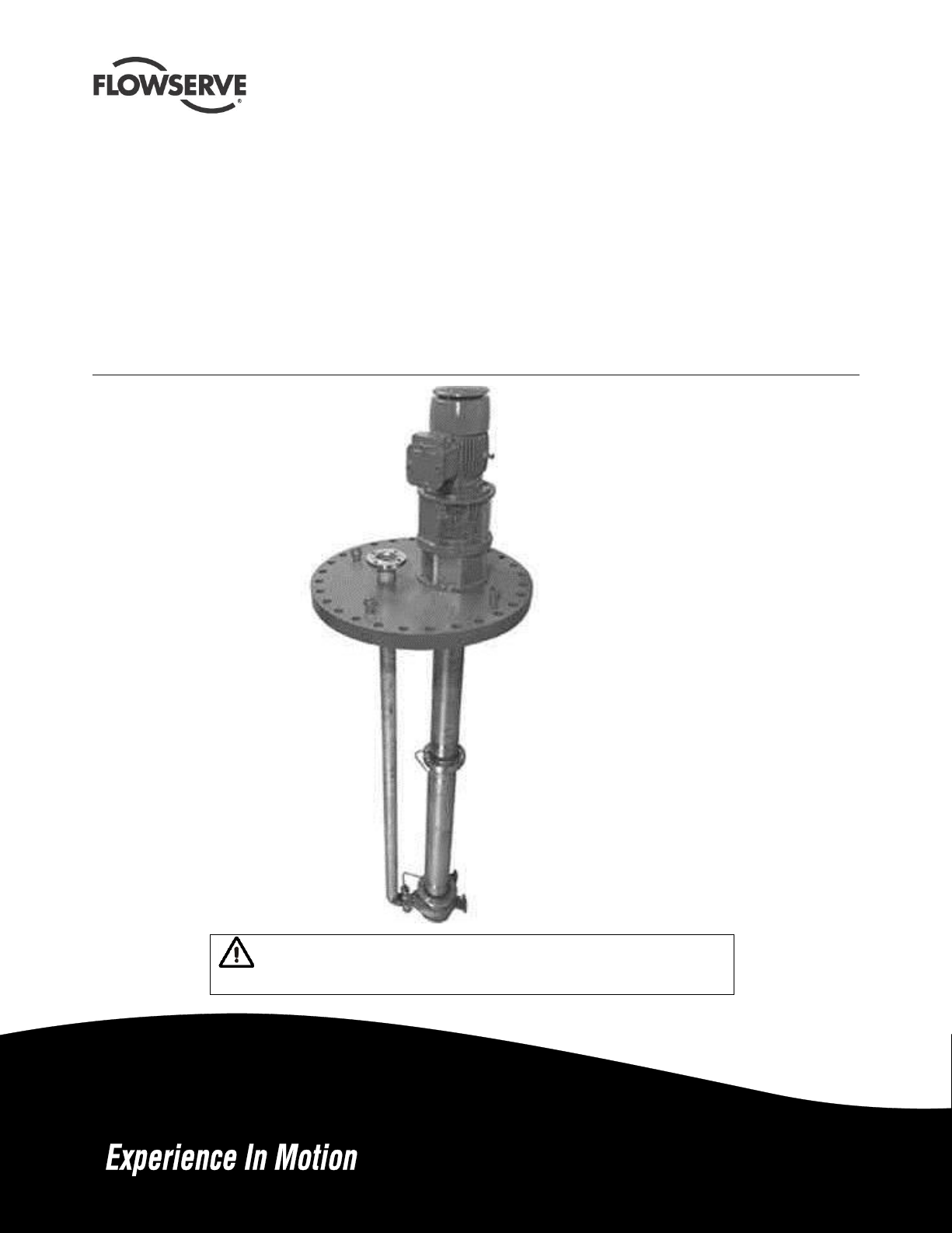
CPXV with Mark 3 ASME hydraulics
Installation
Operation
Maintenance
Centrifugal, modular design, vertical sump pump
PCN=71569291 12-14 (E). Original instructions.
These instructions must be read prior to installing,
operating, using and maintaining this equipment.
Page 2

CPXV with Mark 3 ASME hydraulics ENGLISH 71569291 12-14
CONTENTS
Page
1 INTRODUCTION AND SAFETY ........................... 4
1.1 General ........................................................... 4
1.2 CE marking and approvals .............................. 4
1.3 Disclaimer ....................................................... 4
1.4 Copyright ......................................................... 4
1.5 Duty conditions................................................ 4
1.6 Safety .............................................................. 5
1.7 Nameplate and safety labels ........................... 9
1.8 Specific machine performance ........................ 9
1.9 Noise level ....................................................... 9
2 TRANSPORT AND STORAGE ........................... 10
2.1 Consignment receipt and unpacking ............ 10
2.2 Handling ........................................................ 11
2.3 Lifting ............................................................. 11
2.4 Storage .......................................................... 11
2.5 Recycling and end of product life .................. 11
3 DESCRIPTION .................................................... 12
3.1 Configurations ............................................... 12
3.2 Name nomenclature ...................................... 12
3.3 Design of major parts .................................... 12
3.4 Performance and operating limits ................. 12
4 INSTALLATION .................................................... 13
4.1 Location ......................................................... 13
4.2 Part assemblies............................................. 13
4.3 Foundation .................................................... 13
4.4 Grouting ........................................................ 14
4.5 Piping ............................................................ 14
4.6 Electrical connections ................................... 16
4.7 Protection systems ........................................ 16
Page
6 MAINTENANCE ...................................................24
6.1 General ..........................................................24
6.2 Maintenance schedule ...................................24
6.3 Spare parts ....................................................25
6.4 Recommended spares ..................................26
6.5 Tools required ................................................26
6.6 Casing, seal housing and fastener torques ...26
6.7 Setting impeller clearance .............................27
6.8 Renewal clearances ......................................28
6.9 Disassembly ..................................................29
6.10 Examination of parts ....................................30
6.11 Assembly .....................................................30
7 FAULTS; CAUSES AND REMEDIES ..................33
8 PARTS LISTS AND DRAWINGS .........................35
8.1 CPXV with Mark 3 ASME hydraulics .............35
8.2 CPXV optional features .................................37
8.3 Parts interchangeability .................................42
8.4 General arrangement drawing .......................42
9 CERTIFICATION ..................................................42
10 OTHER RELEVANT DOCUMENTATION
AND MANUALS ..................................................42
10.1 Supplementary User Instruction manuals ...42
10.2 Change notes ..............................................42
10.3 Additional sources of information.................42
5 COMMISSIONING, START-UP, OPERATION AND
SHUTDOWN ...................................................... 17
5.1 Pre-commissioning procedure ...................... 17
5.2 Pump lubricants ............................................ 18
5.3 Open impeller clearance ............................... 20
5.4 Direction of rotation ....................................... 20
5.5 Guarding ....................................................... 20
5.6 Priming and auxiliary supplies ...................... 20
5.7 Starting the pump .......................................... 21
5.8 Running the pump ......................................... 21
5.9 Stopping and shutdown ................................ 23
5.10 Hydraulic, mechanical and electrical duty ... 23
Page 2 of 44 flowserve.com
Page 3

CPXV with Mark 3 ASME hydraulics ENGLISH 71569291 12-14
INDEX
Page
Additional sources (10.3) ......................................... 42
Assembly (6.11) ....................................................... 30
ATEX marking (1.6.4.2) ............................................. 7
Bearing sizes and capacities (5.2.2)........................ 18
CE marking and approvals (1.2) ................................ 4
Certification (9) ........................................................ 42
Change notes (10.2) ................................................ 42
Clearances, impeller (6.7) ....................................... 27
Commissioning and operation (5) ............................ 17
Compliance, ATEX (1.6.4.1) ...................................... 6
Configurations (3.1) ................................................. 12
Copyright (1.4) ........................................................... 4
Design of major parts (3.3) ...................................... 12
Direction of rotation (5.4) ......................................... 20
Disassembly (6.9) .................................................... 28
Disclaimer (1.3) .......................................................... 4
Dismantling (6.9, Disassembly) ............................... 29
Drawings (8) ............................................................ 35
Duty conditions (1.5) .................................................. 4
Electrical connections (4.6) ..................................... 16
End of product life (2.5) ........................................... 11
Examination of parts (6.10) ..................................... 30
Fastener torques (6.6) ............................................. 26
Faults; causes and remedies (7) ............................. 33
Foundation (4.3) ...................................................... 13
General arrangement drawing (8.4) ........................ 42
General assembly drawings (8) ............................... 35
Grouting (4.4) ........................................................... 14
Guarding (5.5) .......................................................... 20
Handling (2.2) .......................................................... 11
Hydraulic, mechanical and electrical duty (5.10) ..... 23
Impeller clearance (5.3 & 6.7)
Inspection (6.2.1 and 6.2.2) ..................................... 25
Installation (4) .......................................................... 13
Lifting (2.3) ............................................................... 11
Location (4.1) ........................................................... 13
Lubrication (5.1.1, 5.2 & 6.2.3)
Lubrication schedule (5.2.5) .................................... 19
Maintenance (6) ....................................................... 24
Maintenance schedule (6.2) .................................... 24
Name nomenclature (3.2) ........................................ 12
Nameplate (1.7.1) ...................................................... 9
Operating limits (3.4.1) ............................................ 12
Ordering spare parts (6.3.1) .................................... 25
Part assemblies (4.2) ............................................... 13
Parts lists (8) ............................................................ 35
Performance (3.4) .................................................... 12
Piping (4.5) .............................................................. 14
Pre-commissioning (5.1) .......................................... 17
Priming and auxiliary supplies (5.6) ......................... 20
Protection systems (4.7) .......................................... 16
Page
Reassembly (6.11, Assembly) .................................30
Receipt and unpacking (2.1) ....................................10
Recommended fill quantities (see 5.2.2) ..................18
Recommended grease lubricants (5.2.3) .................19
Recommended oil lubricants (5.2.1) ........................18
Recommended spares (6.4) .....................................26
Recycling (2.5) .........................................................11
Replacement parts (6.3 & 6.4) ........................... 25/26
Running the pump (5.8) ...........................................21
Safety action (1.6.3) ................................................... 5
Safety labels (1.7.2) ................................................... 9
Safety markings (1.6.1) .............................................. 5
Safety, protection systems (1.6 & 4.7)
Sectional drawings (8) ..............................................35
Setting impeller clearance (6.7) ...............................27
Sound pressure level (1.9, Noise level) ..................... 9
Sources, additional information (10.3) .....................42
Spare parts (6.3) ......................................................25
Specific machine performance (1.8) .......................... 9
Starting the pump (5.7).............................................21
Stop/start frequency (5.8.5) ......................................22
Stopping and shutdown (5.9) ...................................23
Storage, pump (2.4) .................................................11
Storage, spare parts (6.3.2) .....................................25
Supplementary manuals or information sources ......42
Supplementary User Instructions (10.1)...................42
Tools required (6.5) ..................................................25
Torques for fasteners (6.6) .......................................26
Trouble-shooting (see 7) ..........................................33
Vibration (5.8.6) ........................................................22
Page 3 of 44 flowserve.com
Page 4
CPXV with Mark 3 ASME hydraulics ENGLISH 71569291 12-14
1 INTRODUCTION AND SAFETY
1.1 General
These instructions must always be kept
close to the product's operating location or
directly with the product.
Flowserve products are designed, developed and
manufactured with state-of-the-art technologies in
modern facilities. The unit is produced with great
care and commitment to continuous quality control,
utilising sophisticated quality techniques, and safety
requirements.
Flowserve is committed to continuous quality
improvement and being at service for any further
information about the product in its installation and
operation or about its support products, repair and
diagnostic services.
These instructions are intended to facilitate
familiarization with the product and its permitted use.
Operating the product in compliance with these
instructions is important to help ensure reliability in
service and avoid risks. The instructions may not
take into account local regulations; ensure such
regulations are observed by all, including those
installing the product. Always coordinate repair
activity with operations personnel, and follow all plant
safety requirements and applicable safety and health
laws and regulations.
These instructions must be read prior to
installing, operating, using and maintaining the
equipment in any region worldwide. The
equipment must not be put into service until all
the conditions relating to safety, noted in the
instructions, have been met. Failure to follow and
apply the present user instructions is considered
to be misuse. Personal injury, product damage,
delay or failure caused by misuse are not covered
by the Flowserve warranty.
1.2 CE marking and approvals
It is a legal requirement that machinery and equipment
put into service within certain regions of the world shall
conform with the applicable CE Marking Directives
covering Machinery and, where applicable, Low Voltage
Equipment, Electromagnetic Compatibility (EMC),
Pressure Equipment Directive (PED) and Equipment for
Potentially Explosive Atmospheres (ATEX).
Where applicable, the Directives and any additional
Approvals, cover important safety aspects relating to
machinery and equipment and the satisfactory provision
of technical documents and safety instructions. Where
applicable this document incorporates information
relevant to these Directives and Approvals.
To confirm the Approvals applying and if the product is
CE marked, check the serial number plate markings
and the Certification. (See section 9, Certification.)
1.3 Disclaimer
Information in these User Instructions is believed to
be complete and reliable. However, in spite of all of
the efforts of Flowserve Corporation to provide
comprehensive instructions, good engineering and
safety practice should always be used.
Flowserve manufactures products to exacting
International Quality Management System Standards as
certified and audited by external Quality Assurance
organisations. Genuine parts and accessories have
been designed, tested and incorporated into the
products to help ensure their continued product quality
and performance in use. As Flowserve cannot test
parts and accessories sourced from other vendors the
incorrect incorporation of such parts and accessories
may adversely affect the performance and safety
features of the products. The failure to properly select,
install or use authorised Flowserve parts and
accessories is considered to be misuse. Damage or
failure caused by misuse is not covered by the
Flowserve warranty. In addition, any modification of
Flowserve products or removal of original components
may impair the safety of these products in their use.
1.4 Copyright
All rights reserved. No part of these instructions may
be reproduced, stored in a retrieval system or
transmitted in any form or by any means without prior
permission of Flowserve.
1.5 Duty conditions
This product has been selected to meet the
specifications of your purchaser order. The
acknowledgement of these conditions has been sent
separately to the Purchaser. A copy should be kept
with these instructions.
The product must not be operated beyond
the parameters specified for the application.
If there is any doubt as to the suitability of the
product for the application intended, contact
Flowserve for advice, quoting the serial number.
If the conditions of service on your purchase order are
going to be changed (for example liquid pumped,
temperature or duty) it is requested that the user seeks
the written agreement of Flowserve before start up.
Page 4 of 44 flowserve.com
Page 5
CPXV with Mark 3 ASME hydraulics ENGLISH 71569291 12-14
1.6 Safety
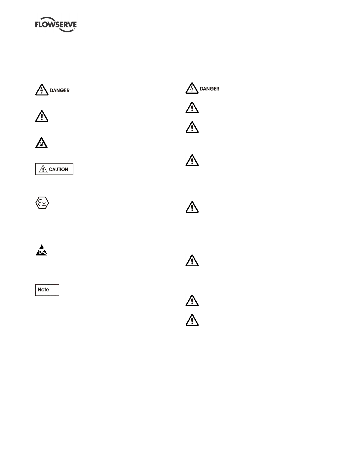
1.6.1 Summary of safety markings
These User Instructions contain specific safety
markings where non-observance of an instruction would
cause hazards. The specific safety markings are:
This symbol indicates electrical safety
instructions where non-compliance will involve a high
risk to personal safety or the loss of life.
This symbol indicates safety instructions where
non-compliance would affect personal safety and could
result in loss of life.
This symbol indicates “hazardous and toxic fluid”
safety instructions where non-compliance would affect
personal safety and could result in loss of life.
This symbol indicates safety instructions
where non-compliance will involve some risk to safe
operation and personal safety and would damage the
equipment or property.
This symbol indicates explosive atmosphere zone
marking according to ATEX. It is used in safety
instructions where non-compliance in the hazardous
area would cause the risk of an explosion, and will
involve a high risk to personal safety and could result in
loss of life.
This symbol is used in safety instructions to
remind not to rub non-metallic surfaces with a dry
cloth; ensure the cloth is damp. It is used in safety
instructions where non-compliance in the hazardous
area would cause the risk of an explosion.
This sign is not a safety symbol but indicates
an important instruction in the assembly process.
1.6.2 Personnel qualification and training
All personnel involved in the operation, installation,
inspection and maintenance of the unit must be
qualified to carry out the work involved. If the
personnel in question do not already possess the
necessary knowledge and skill, appropriate training
and instruction must be provided. If required the
operator may commission the manufacturer/supplier
to provide applicable training.
Always coordinate repair activity with operations and
health and safety personnel, and follow all plant
safety requirements and applicable safety and health
laws and regulations.
1.6.3 Safety action
This is a summary of conditions and actions to help
prevent injury to personnel and damage to the
environment and to equipment. For products used
in potentially explosive atmospheres section 1.6.4
also applies.
NEVER DO MAINTENANCE WORK
WHEN THE UNIT IS CONNECTED TO POWER
GUARDS MUST NOT BE REMOVED WHILE
THE PUMP IS OPERATIONAL
DRAIN THE PUMP AND ISOLATE PIPEWORK
BEFORE DISMANTLING THE PUMP
The appropriate safety precautions should be taken
where the pumped liquids are hazardous.
FLUORO-ELASTOMERS (When fitted.)
When a pump has experienced temperatures over
250 ºC (482 ºF), partial decomposition of fluoroelastomers (example: Viton) will occur. In this
condition these are extremely dangerous and skin
contact must be avoided.
HANDLING COMPONENTS
Many precision parts have sharp corners and the
wearing of appropriate safety gloves and equipment
is required when handling these components. To lift
heavy pieces above 25 kg (55 lb) use a crane
appropriate for the mass and in accordance with
current local regulations.
THERMAL SHOCK
Rapid changes in the temperature of the liquid within
the pump can cause thermal shock, which can result
in damage or breakage of components and should be
avoided.
NEVER APPLY HEAT TO REMOVE IMPELLER
Trapped lubricant or vapor could cause an explosion.
HOT (and cold) PARTS
If hot or freezing components or auxiliary heating
supplies can present a danger to operators and
persons entering the immediate area action must be
taken to avoid accidental contact. If complete
protection is not possible, the machine access must
be limited to maintenance staff only, with clear visual
warnings and indicators to those entering the
immediate area. Note: bearing housings must not be
insulated and drive motors and bearings may be hot.
If the temperature is greater than 80 ºC (175 ºF) or
below -5 ºC (23 ºF) in a restricted zone, or exceeds
local regulations, action as above shall be taken.
Page 5 of 44 flowserve.com
Page 6
CPXV with Mark 3 ASME hydraulics ENGLISH 71569291 12-14
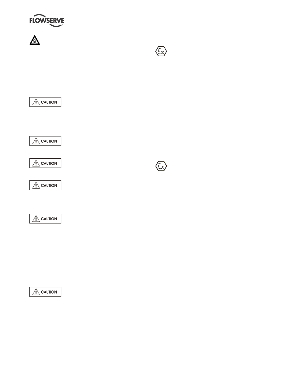
HAZARDOUS LIQUIDS
When the pump is handling hazardous liquids care
must be taken to avoid exposure to the liquid by
appropriate siting of the pump, limiting personnel
access and by operator training. If the liquid is
flammable and or explosive, strict safety procedures
must be applied.
Gland packing must not be used when pumping
hazardous liquids.
PREVENT EXCESSIVE EXTERNAL
PIPE LOAD
Do not use pump as a support for piping. Do not mount
expansion joints, unless allowed by Flowserve in
writing, so that their force, due to internal pressure, acts
on the pump flange.
NEVER RUN THE PUMP DRY
Liquid level controls are recommended to avoid the risk
of dry running.
ENSURE CORRECT LUBRICATION
(See section 5, Commissioning, startup, operation and
shutdown.)
ONLY CHECK DIRECTION OF
MOTOR ROTATION WITH COUPLING ELEMENT/
PINS REMOVED
Starting in reverse direction of rotation will damage the
pump.
START THE PUMP WITH OUTLET
VALVE PART OPENED
(Unless otherwise instructed at a specific point in the
User Instructions.)
This is recommended to minimize the risk of
overloading and damaging the pump or motor at full or
zero flow. Pumps may be started with the valve further
open only on installations where this situation cannot
occur. The pump outlet control valve may need to be
adjusted to comply with the duty following the run-up
process. (See section 5, Commissioning start-up,
operation and shutdown.)
DO NOT RUN THE PUMP AT
ABNORMALLY HIGH OR LOW FLOW RATES
Operating at a flow rate higher than normal or at a flow
rate with no back pressure on the pump may overload
the motor and cause cavitation. Low flow rates may
cause a reduction in pump/bearing life, overheating of
the pump, instability and cavitation/vibration.
1.6.4 Products used in potentially explosive
atmospheres
Measures are required to:
Avoid excess temperature
Prevent build up of explosive mixtures
Prevent the generation of sparks
Prevent leakages
Maintain the pump to avoid hazard
The following instructions for pumps and pump units
when installed in potentially explosive atmospheres
must be followed to help ensure explosion protection.
For ATEX, both electrical and non-electrical equipment
must meet the requirements of European Directive
2014/34/EU (previously 94/9/EC which remains valid
until 20 April 2016 during the transition). Always
observe the regional legal Ex requirements eg Ex
electrical items outside the EU may be required certified
to other than ATEX eg IECEx, UL.
1.6.4.1 Scope of compliance
Use equipment only in the zone for which it is
appropriate. Always check that the driver, drive
coupling assembly, seal and pump equipment are
suitably rated and/or certified for the classification of the
specific atmosphere in which they are to be installed.
Where Flowserve has supplied only the bare shaft
pump, the Ex rating applies only to the pump. The
party responsible for assembling the ATEX pump set
shall select the coupling, driver and any additional
equipment, with the necessary CE Certificate/
Declaration of Conformity establishing it is suitable for
the area in which it is to be installed.
The motor, coupling, pump thrust bearing and seal
can be made compliant with ATEX Directive
2014/34/EU (previously 94/9/EC which remains valid
until 20 April 2016 during the transition) for
Equipment Categories 2 and 3 as required by the
duty conditions.
See the pump nameplate and Declaration of Conformity
for the pump classification. The pump column below
sole plate will also generally be to the same category
however in some applications the section of the pump
below sole plate and above liquid will have been
designed to Category 1, whereas above sole plate
Category 2 or 3 will apply. (See section 1.6.4.2.)
Page 6 of 44 flowserve.com
Page 7
CPXV with Mark 3 ASME hydraulics ENGLISH 71569291 12-14
Temperature class
to EN 13463-1
Maximum surface
temperature permitted
Temperature limit of
liquid handled
T6
T5
T4
T3
T2
T1
85 °C (185 °F)
100 °C (212 °F)
135 °C (275 °F)
200 °C (392 °F)
300 °C (572 °F)
450 °C (842 °F)
65 °C (149 °F) *
80 °C (176 °F) *
115 °C (239 °F) *
180 °C (356 °F) *
275 °C (527 °F) *
400 °C (752 °F) *
The pump will then be supplied with a copy of the
Certificate of Approval by a Notified Body and marked
with both categories. Users must pay particular
attention to pump operation and maintenance
instructions because of the hazard of the explosive
atmosphere.
The output from a variable frequency drive (VFD) can
cause additional heating effects in the motor and so, for
pumps sets with a VFD, the ATEX Certification for the
motor must state that it is covers the situation where
electrical supply is from the VFD. This particular
requirement still applies even if the VFD is in a safe area.
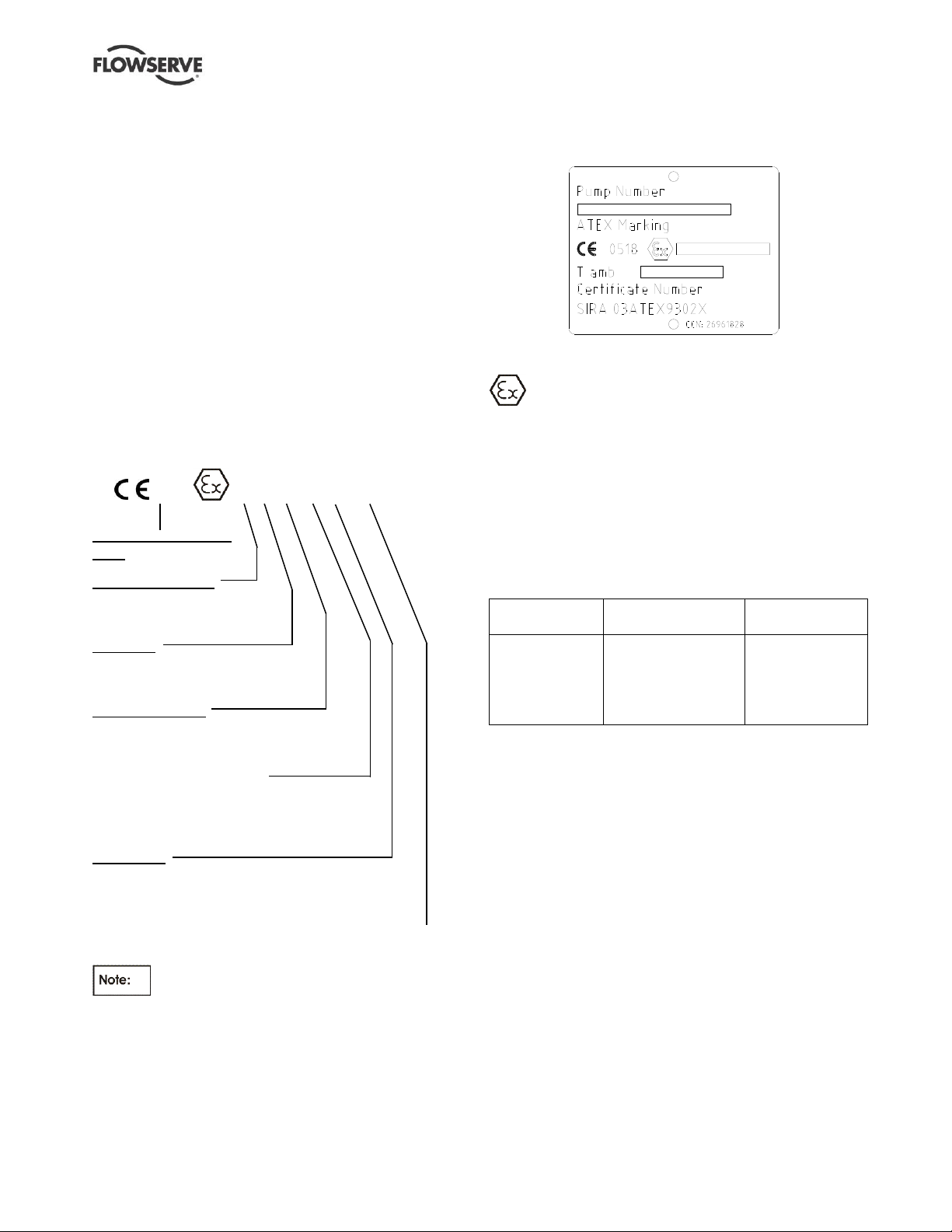
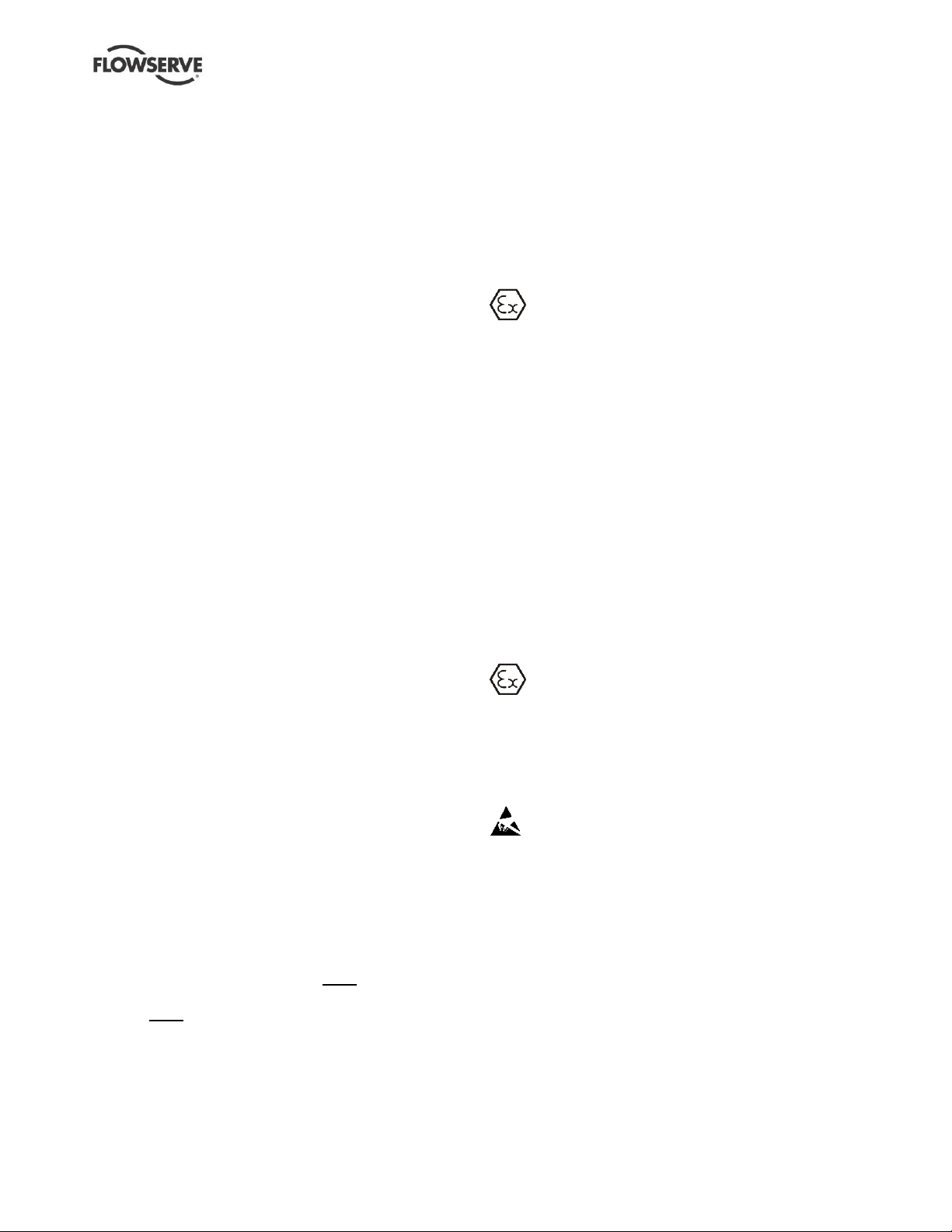
1.6.4.2 Marking
An example of ATEX equipment marking is shown
below. The actual classification of the pump will be
engraved on the nameplate or in the case of Category
1, below the sole plate on a special ATEX marking
plate.
0518 II 1G/2GD cb IIC 135 ºC (T4)
External examination
body *
Equipment Group
I = Mining
II = Non-mining
Category
2 or M2 = High level protection
3 = normal level of protection
Gas and/or Dust
G = Gas
D = Dust
c = Constructional safety
(in accordance with EN13463-5)
b = Control of ignition source
(in accordance with EN13463-6)
Gas Group
IIA – Propane (Typical)
IIB – Ethylene (Typical)
IIC – Hydrogen (Typical)
Maximum surface temperature (Temperature Class)
(see section 1.6.4.3.)
* The external ATEX examination body
reference is included in the pump marking when the
Category is 1/2 or 1/3. In that situation, the 1 before
the /2 or /3 identifies the special case where the
pump is Category 1 below the sole plate and 2 or 3
above the sole plate.
For ATEX Group II Category 1 below the sole plate a
special ATEX marking plate is used. An example of
this is shown below.
1.6.4.3 Avoiding excessive surface temperatures
ENSURE THE EQUIPMENT TEMPERATURE
CLASS IS SUITABLE FOR THE HAZARD ZONE
Pumps have a temperature class as stated in the
ATEX Ex rating on the nameplate.
The surface temperature on the pump is influenced
by the temperature of the liquid handled. The
maximum permissible liquid temperature depends on
the ATEX temperature class and must not exceed the
values in the table that follows.
* The table only takes the ATEX temperature class into consideration.
Pump design or material, as well as component design or material,
may further limit the liquid maximum working temperature
The temperature rise at the seals and bearings and
due to the minimum permitted flow rate is taken into
account in the temperatures stated.
The operator is responsible to ensure the specified
maximum liquid temperature is not exceeded.
Temperature classification “Tx” is used when the liquid
temperature varies and when the pump is required to be
used in differently classified potentially explosive
atmospheres. In this case the user is responsible for
ensuring that the pump surface temperature does not
exceed that permitted in its actual installed location.
Do not attempt to check the direction of rotation with the
coupling element/pins fitted due to the risk of severe
contact between rotating and stationary components.
Page 7 of 44 flowserve.com
Page 8
CPXV with Mark 3 ASME hydraulics ENGLISH 71569291 12-14
Where there is any risk of the pump being run against
a closed valve generating high liquid and casing
external surface temperatures fit an external surface
temperature protection device.
Avoid mechanical, hydraulic or electrical overload by
using motor overload trips, a temperature or power
monitor and make routine vibration monitoring checks.
In dirty or dusty environments, regular checks must
be made and dirt removed from areas around close
clearances, bearing housings and motors.
The equipment utilises polymer based seals and
bearing surfaces that could be corroded if they
are in contact with unsuitable liquids or gases.
These surfaces are important for the operation of
the pump. Contact Flowserve if you are uncertain
about the performance of these materials with
respect to aggressive substances that may be
present in the hazardous area.
The pump casing must be flooded with liquid to the
minimum level on the dimensional General
Arrangement (GA) drawing, at any time that the pump
is operated. On pumps furnished to Group II
Category 1 below the sole plate, monitoring of the
level with a pump cut out on low level is required.
Where there is the potential hazard of a loss of a seal
barrier fluid the barrier fluid system must be monitored.
Where there is a risk that the external flush to a seal or
bearing could fail, for example by freezing, blocking by
debris or loss of supply pressure, then the flow must be
monitored.
Where there is product flush via filters then flow must
be monitored.
Visual indicators are suitable when equipment is
regulary inspected, but sensors connected to the pump
control system must be used if the pump runs remotely.
For Category 2 equipment the monitoring must create
an alarm to the plant operator or shut down the pump.
For equipment to category 1/2 or 1/3 with external flush
or filtered product flush, the flow to each line bearing
must be separately monitored and temperature sensors
fitted on each line bearing that is connected to the
pump control system. The monitoring equipment must
be suitable for the hazardous area.
For equipment to category 1/2 or 1/3 the presence of
seal barrier liquid and the temperature of the inboard
seal must both be monitored and connected to the
pump control to create an alarm signal to the operator,
or to shut down the pump.
See also sections 5.8.2 to 5.8.6.
1.6.4.4 Preventing the build-up of explosive
mixtures
ENSURE THE PUMP IS PROPERLY FILLED
AND VENTED AND DOES NOT RUN DRY
Ensure the pump and relevant suction and discharge
pipeline system is totally filled with liquid at all times
during the pump operation, so that an explosive
atmosphere is prevented. In addition it is essential to
make sure that seal chambers, auxiliary shaft seal
systems and any heating and cooling systems are
properly filled.
If the operation of the system cannot avoid this
condition, fit an appropriate dry run protection device
(for example liquid detection or a power monitor).
To avoid potential hazards from fugitive emissions of
vapor or gas to atmosphere the surrounding area
must be well ventilated.
1.6.4.5 Preventing sparks
To prevent a potential hazard from mechanical
contact, the coupling guard must be non-sparking
and anti-static for Category 2.
To avoid the potential hazard from random induced
current generating a spark, the earth contact on the
baseplate must be used.
Avoid electrostatic charge: do not rub non-metallic
surfaces with a dry cloth; ensure cloth is damp.
For ATEX the coupling must be selected to comply with
the requirements of European Directive 2014/34/EU
(previously 94/9/EC which remains valid until 20 April
2016 during the transition). Correct coupling alignment
must be maintained.
Page 8 of 44 flowserve.com
Page 9
CPXV with Mark 3 ASME hydraulics ENGLISH 71569291 12-14
1.6.4.6 Preventing leakage
The pump must only be used to handle liquids
for which it has been approved to have the correct
corrosion resistance.
Avoid entrapment of liquid in the pump and associated
piping due to closing of suction and discharge valves,
which could cause dangerous excessive pressures to
occur if there is heat input to the liquid. This can occur if
the pump is stationary or running.
Bursting of liquid containing parts due to freezing
must be avoided by draining or protecting the pump
and ancillary systems.
Where there is the potential hazard of a loss of a seal
barrier fluid or external flush, the fluid must be monitored.
If leakage of liquid to atmosphere can result in a
hazard, install a liquid detection device.
1.6.4.7 Maintenance to avoid the hazard
CORRECT MAINTENANCE IS REQUIRED TO
AVOID POTENTIAL HAZARDS WHICH GIVE A
RISK OF EXPLOSION
The responsibility for compliance with maintenance
instructions is with the plant operator.
To avoid potential explosion hazards during
maintenance, the tools, cleaning and painting
materials used must not give rise to sparking or
adversely affect the ambient conditions. Where there
is a risk from such tools or materials, maintenance
must be conducted in a safe area.
It is recommended that a maintenance plan and
schedule is adopted. (See section 6, Maintenance.)
1.7 Nameplate and safety labels
1.7.1 Nameplate
For details of nameplate, see the Declaration of
Conformity. Where a unit is ATEX Group II Category
1 below the sole plate there is an additional ATEX
marking plate. (See section 1.6.4.2 Marking.)
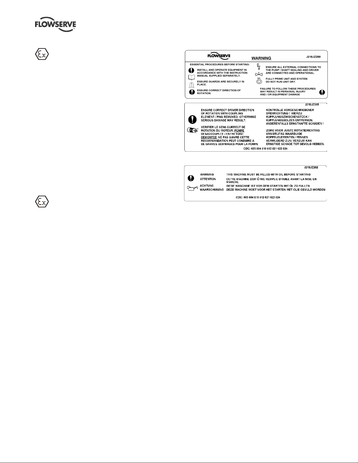
1.7.2 Safety labels
Oil lubricated units only:
1.8 Specific machine performance
For performance parameters see section 1.5, Duty
conditions. Where performance data has been
supplied separately to the purchaser these should be
obtained and retained with these User Instructions if
required.
1.9 Noise level
Attention must be given to the exposure of personnel
to the noise, and local legislation will define when
guidance to personnel on noise limitation is required,
and when noise exposure reduction is mandatory.
This is typically 80 to 85 dBA.
The usual approach is to control the exposure time to
the noise or to enclose the machine to reduce emitted
sound. You may have already specified a limiting
noise level when the equipment was ordered,
however if no noise requirements were defined, then
attention is drawn to the following table to give an
indication of equipment noise level so that you can
take the appropriate action in your plant.
Pump noise level is dependent on a number of
operational factors, flow rate, pipework design and
acoustic characteristics of the building, and so the
values given are subject to a 3 dBA tolerance and
cannot be guaranteed.
Page 9 of 44 flowserve.com
Page 10
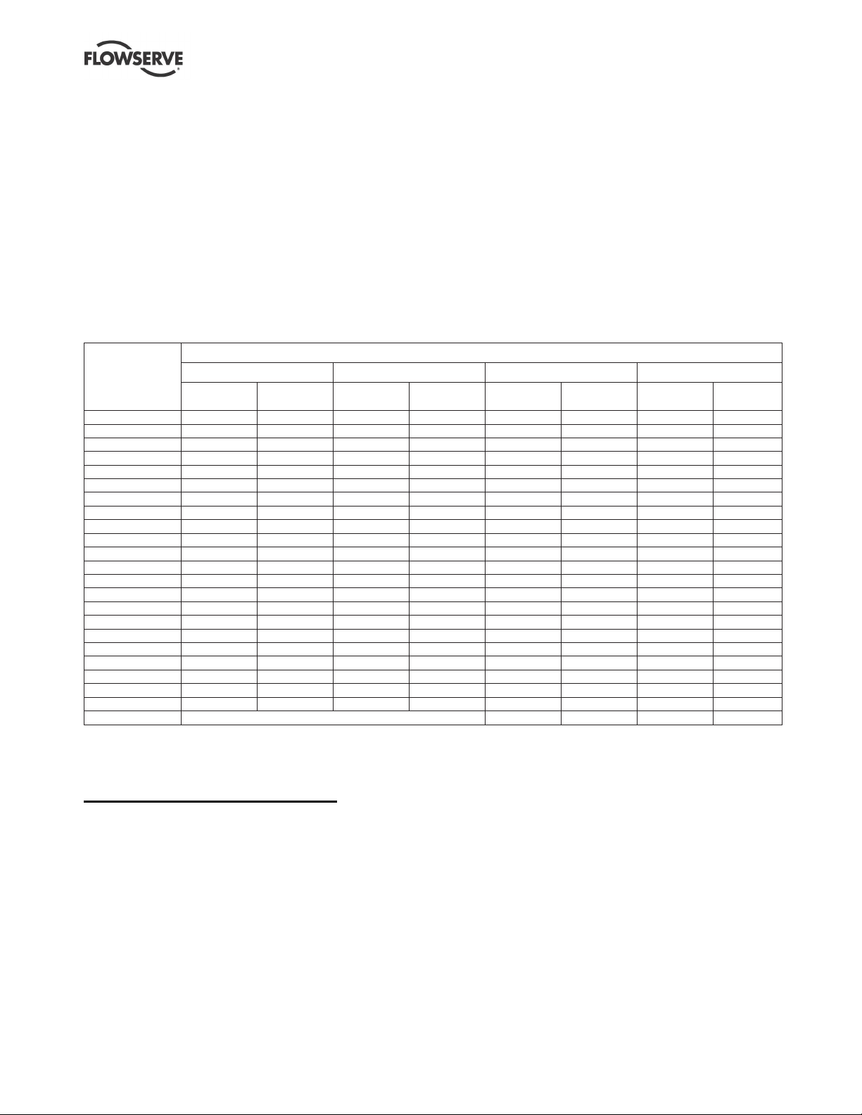
CPXV with Mark 3 ASME hydraulics ENGLISH 71569291 12-14
Motor size
and speed
kW (hp)
Typical sound pressure level LpA at 1 m reference 20 μPa, dBA
3550 r/min
2900 r/min
1750 r/min
1450 r/min
Pump
only
Pump and
motor
Pump
only
Pump and
motor
Pump
only
Pump and
motor
Pump
only
Pump and
motor
<0.55 (<0.75)
58
65
50
58
50
52
50
52
0.75 (1)
60
65
52
59
51
54
51
54
1.1 (1.5)
62
67
54
60
55
57
53
56
1.5 (2)
63
66
55
63
56
59
54
58
2.2 (3)
64
69
57
65
58
62
56
60
3 (4)
63
71
58
68
59
64
57
62
4 (5)
64
72
60
69
61
65
59
63
5.5 (7.5)
66
73
62
71
63
67
61
65
7.5 (10)
67
73
63
71
64
69
62
67
11 (15)
69
76
65
73
66
71
64
69
15 (20)
71
77
67
74
68
72
66
70
18.5 (25)
72
78
68
75
69
70
67
70
22 (30)
73
78
69
76
70
71
68
71
30 (40)
75
79
71
77
72
72
70
72
37 (50)
76
80
72
78
73
73
71
73
45 (60)
77
81
73
79
74
74
72
74
55 (75)
78
81
74
79
75
75
73
75
75 (100)
80
83
76
81
77
76
75
76
90 (120)
81
84
77
81
78
77
76
77
110 (150)
82
85
78
82
79
78
77
78
150 (200)
84
87
80
84
81
79
79
79
200 (270)
① ① ①
①
81
81
79
79
300 (400)
–
83
86
81
82
Similarly the motor noise assumed in the “pump and
motor” noise is that typically expected from standard
and high efficiency motors when on load directly driving
the pump. Note that a motor driven by an inverter may
show an increased noise at some speeds.
If a pump unit only has been purchased for fitting with
your own driver then the “pump only” noise levels in the
table should be combined with the level for the driver
obtained from the supplier. Consult Flowserve or a
noise specialist if assistance is required in combining
the values.
It is recommended that where exposure approaches
the prescribed limit, then site noise measurements
should be made.
The values are in sound pressure level LpA at 1 m
(3.3 ft) from the machine, for “free field conditions
over a reflecting plane”.
For estimating sound power level LWA (re 1 pW) then
add 14 dBA to the sound pressure value.
Values in the table below are valid for the preferred
range of pump operation, 80 % to 110 % of B.E.P.
The noise level of machines in this range will most likely be of values which require noise exposure control, but typical values are inappropriate.
Note: for 1 180 and 960 r/min reduce 1 450 r/min values by 2 dBA. For 880 and 720 r/min reduce 1 450 r/min values by 3 dBA.
2 TRANSPORT AND STORAGE
2.1 Consignment receipt and unpacking
Immediately after receipt of the equipment it must be
checked against the delivery/shipping documents for
its completeness and that there has been no damage
in transportation. Any shortage and/or damage must
be reported immediately to Flowserve and must be
received in writing within one month of receipt of the
equipment. Later claims cannot be accepted.
Check any crate, boxes or wrappings for any
accessories or spare parts that may be packed
separately with the equipment or attached to side
walls of the box or equipment.
Each product has a unique serial number. Check
that this number corresponds with that advised and
always quote this number in correspondence as well
as when ordering spare parts or further accessories.
Page 10 of 44 flowserve.com
Page 11
CPXV with Mark 3 ASME hydraulics ENGLISH 71569291 12-14
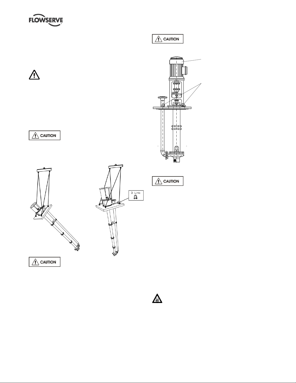
For lifting the driver on to or off the
pump refer to the dimension
drawing and instructions from the
driver manufacturer
Lift points for the pump
2.2 Handling
Boxes, crates, pallets or cartons may be unloaded
using fork lift vehicles or slings dependent on their
size and construction.
2.3 Lifting
A crane must be used for all pump sets in
excess of 25 kg (55 lb). Fully trained personnel must
carry out lifting, in accordance with local regulations.
Pumps with drivers over approximately 7.5 kW, are
supplied with the pump packed as a separate item from
the driver. For improved stability unbolt the driver and
lift the driver and pump separately. They should be
lifted separately into their installed position, using lifting
points on the pump soleplate and on the motor.
Pumps and motors often have integral
lifting lugs or eye bolts. These are only intended for
use in lifting the individual piece of equipment.
Before lifting the driver alone, refer to the
manufacturer’s instructions.
To avoid distortion, the pump unit
should be lifted as shown.
2.4 Storage
When lifting pumps with drivers fitted,
the resulting center of gravity may be above the lifting
points, and the method of slinging must prevent the
machine tipping during the lift. Slings, ropes and other
lifting gear must be positioned where they cannot slip
and where a balanced lift is obtained.
Most units are supplied with four lifting points on the
pump sole plate [6140]. Attach D-links onto all four
lifting points. Use a spreader beam attached to the
overhead crane and fit two D-links. Ensure the sling is
not in contact with the pin of any of the D-links. Lift the
pump up to the vertical, as shown above using the
D-links on the sole plate.
Store the pump in a clean, dry location
away from vibration. Leave piping connection covers in
place to keep dirt and other foreign material out of pump
casing. Turn pump at intervals to prevent brinelling of
the bearings and the seal faces, if fitted, from sticking.
The pump may be stored as above for up to six
months. Consult Flowserve for preservative actions
when a longer storage period is needed.
2.5 Recycling and end of product life
At the end of the service life of the product or its
parts, the relevant materials and parts should be
recycled or disposed of using an environmentally
acceptable method and local requirements. If the
product contains substances that are harmful to the
environment, these should be removed and disposed
of in accordance with current regulations. This also
includes the liquids and or gases that may be used in
the "seal system" or other utilities.
Make sure that hazardous substances are
disposed of safely and that the correct personal
protective equipment is used. The safety
specifications must be in accordance with the current
regulations at all times.
Page 11 of 44 flowserve.com
Page 12

CPXV with Mark 3 ASME hydraulics ENGLISH 71569291 12-14
3 DESCRIPTION
3.1 Configurations
The pump is a modular designed centrifugal pump
that can be built to achieve almost all chemical liquid
pumping requirements.
3.2 Name nomenclature
The pump size will be engraved on the nameplate
typically as below:
Impeller drive size 3K10X8CPXV-16HRV
Casing nominal suction
size in inches
Casing discharge size in inches
CPXV lineshaft configuration
Nominal maximum impeller diameter in inches
H = this pump is designed for a higher flow capacity than another
pump with the same basic designation. (Examples: 4X3-10 and
4X3-10H; 6X4-10 and 6X4-10H; 10X8-16 and 10X8-16H)
HH = this pump is designed for a higher head than another pump with
the same basic designation. (Example: 4X3-13 and 4X3-13HH)
HC = this pump bottom wet end is made from very hard high
chrome and the impeller is always an OP
A = this pump has been redesigned from an earlier version. The
impeller and casing are no longer interchangeable with the
earlier version
RV = Reverse vane type impeller
OP = Open impeller
The typical nomenclature above is the general guide
to the CPXV configuration description. Identify the
actual pump size and serial number from the pump
nameplate. Check that this agrees with the
applicable certification provided.
3.3 Design of major parts
3.3.1 Pump casing
The pump casing is designed for operation when
submerged in the sump liquid. It is from the ASME
B73.1 hydraulics series with inch studs.
High chrome iron casing has a much
reduced pressure rating of 12.6 bar (183 psi).
3.3.1.1 Agitation system
This option is on high chrome iron/tungsten carbide
coated casings.
3.3.2 Impeller
Depending on the wet end hydraulic, the impeller is
either reverse vane or open. (High Chrome iron is
only open.)
Drive size: 3K = Group 3, 2K = Group 2, 1K = Group 1.
3.3.3 Shaft
The shaft has a keyed drive coupling. It is supported by
rolling bearing(s) above the sole plate and journal
bearing(s) below.
3.3.4 Bearing housing
The bearing housing enables adjustment of impeller
face clearance on the impeller via the bearing carrier
jacking screws. High temperature pumps have a
cooling fan above the pump thrust bearing housing
and a heat sink disk fan below the pump thrust
bearing but above the sole plate shaft seal.
3.3.5 Pump bearings and lubrication
The pump is fitted with a thrust type ball bearing that
may be configured differently dependent on use.
The thrust bearing(s) may be grease or oil lubricated
depending upon the application.
The journal (line) bearings may be lubricated by
product or from an external source depending upon
the application.
3.3.6 Sole plate shaft seal
The modular design enables one of a number of
sealing options to be fitted. The option of a rigid
coupling below the thrust bearing and above a
mechanical seal provides back-pull-out servicing of
the mechanical seal; removing the motor extends the
back-pull-out feature to the thrust bearing.
3.3.7 Driver
The pump is normally driven by a flange mounted electric
motor. An air or hydraulic motor may be utilized.
The position of the terminal box can be changed by
rotating the complete motor. To do this, remove the
fasteners from the motor flange, rotate the motor and
re-fit the fasteners.
3.3.8 Accessories
Accessories may be fitted when specified by the
customer.
3.4 Performance and operating limits
This product has been selected to meet the
specifications of the purchase order. See section 1.5.
The following data is included as additional information to
help with your installation. It is typical, and factors such
as temperature, materials, and seal type may influence
this data. If required, a definitive statement for your
particular application can be obtained from Flowserve.
Page 12 of 44 flowserve.com
Page 13

CPXV with Mark 3 ASME hydraulics ENGLISH 71569291 12-14
3.4.1 Operating limits
Maximum pump ambient temperature: +55 ºC (131 ºF)
where driver is also rated for this ambient.
Maximum pump speed: refer to the nameplate.
3.4.2 Energy efficiency operation of pumps
The pump supplied will have been selected from
Flowserve’s extensive product line to have optimum
efficiency for the application. If supplied with an electric
motor then the motor will meet or exceed current
legislation for motor efficiency. However it is the way
the pump is operated which has the greatest impact on
the amount and cost of energy used during the
operating life of the pump. The following are key points
in achieving minimum operating cost for the equipment:
Design the pipe system for minimum friction losses
Ensure that the control system switches off the
pump when not required
In a multi-pump system run the minimum number
of pumps
Try to avoid systems which by-pass excess flow
As far as possible avoid controlling pump flow by
throttle valves
When commissioned, check that the pump
operates at the duty specified to Flowserve
If it has been found that the pump head and flow
exceed that required, trim the pump impeller
diameter
Ensure that the pump is operating with sufficient
NPSH available
Use variable speed drives for systems that
require variable flow. A VFD for an induction
motor is a particularly effective way of achieving
speed variation and energy/cost reduction
Notes for VFD usage:
o make sure that the motor is compatible with
VFD
o do not over-speed the pump without checking
the power capability with Flowserve
o on systems with high static head, speed
reduction is limited. Avoid running the pump
at a speed which gives low or zero flow
o do not run a low speed and flow rate that lets
solids settle out of suspension in the pipework
o do not use a VFD for a fixed flow
requirement; it will introduce power losses
Select high efficiency motors
If replacing a standard motor with a high
efficiency motor it will run faster and the pump
could take more power. Reduce the impeller
diameter to achieve energy reduction
If the pump system pipework or equipment is
changed or process duty is changed, check that
the pump is still correctly sized
Periodically check that the pipe system has not
become corroded or blocked
Periodically check that the pump is operating at
the flow, head and power expected and that the
efficiency has not reduced with erosion or
corrosion damage
4 INSTALLATION
Equipment operated in hazardous locations
must comply with the relevant explosion protection
regulations. See section 1.6.4, Products used in
potentially explosive atmospheres.
4.1 Location
The pump should be located to allow room for
access, ventilation, maintenance and inspection with
ample headroom for lifting and should be as close as
practicable to the supply of liquid to be pumped.
Refer to the general arrangement drawing for the
pump set.
4.2 Part assemblies
On pump sets the coupling elements are supplied
loose. It is the responsibility of the installer to ensure
that the pump set is finally lined up and checked as
detailed in section 4.5.5, Final checks.
4.3 Foundation
There are many methods of installing
pump units to their foundations. The correct method
depends on the size of the pump unit, its location and
noise and vibration limitations. Non-compliance with
the provision of correct foundation and installation
may lead to failure of the pump and, as such, would
be outside the terms of the warranty.
The sump pump mounting should have concrete or
metal to support it around its edges.
4.3.1 Levelling
The sole plate must be level so that the pump column
hangs vertically; confirmed by inspection. With the
motor removed check the top face of the machined
motor pedestal [3160] is set level to 0.05 mm (0.002 in.)
or 0.2 mm/m (0.0025 in./ft) maximum.
Larger size motors are shipped unfitted. The motor will
need to be fitted after completion of the pump
foundation installation. Turn shaft clockwise by hand to
ensure it is free to turn.
Page 13 of 44 flowserve.com
Page 14
CPXV with Mark 3 ASME hydraulics ENGLISH 71569291 12-14
4.3.2 Packing pieces
Where the sole plate and its counter-face do not each
have a machined face, packing pieces (metallic shims)
will need to be placed evenly adjacent to the foundation
(holding down) bolts to avoid “soft-foot” distortion. Turn
shaft clockwise by hand to ensure it is free to turn.
Soft-foot distortion may significantly increase vibration
and damage equipment by causing distortion and
should normally be inspected. If high vibration occurs
when pump is run (see Section 5, Commissioning, start-
up, operation and shutdown) place a vibration meter at
the side of the motor as soft-foot is most effectively
reduced when the vibration is reduced to a minimum.
Overall vibration measurement can be used - it is not
necessary to use a vibration spectrum to pick up softfoot which occurs at 1x running speed and should be
the first issue to check.
To adjust for soft-foot use a dial gauge on the sole
plate top face near to the holding down bolt, zero it,
record the soft-foot spring in the sole plate and undo
one holding down bolt at a time.
Soft-foot is removed by inserting packing pieces
(metallic shims) equal to or slightly less than the softfoot spring amount recorded at the individual holding
down point locations. Re-torque the holding down bolt.
Continue this procedure for each holding down bolt
position in turn, one at a time. The thickness of
packing pieces (metallic shims) adjacent to an
individual holding down bolt should not exceed 3 mm
(0.12 in.); ie soft-foot spring is not to exceed 3 mm
(0.12 in.) at any individual location.
4.4 Grouting
Where applicable, grout in the foundation bolts.
Grouting provides solid contact between the pump unit
and foundation, prevents lateral movement of vibrating
equipment and dampens resonant vibrations.
4.5 Piping
Protective covers are fitted to the pipe
connections to prevent foreign bodies entering during
transportation and installation. Ensure that these
covers are removed from the pump before connecting
any pipes.
Category 1/2 and 1/3 pumps must be fitted with a
strainer.
Maximum forces and moments allowed on the pump
flanges vary with the pump size and type. To minimize
these forces and moments that may, if excessive, cause
misalignment, hot bearings, worn couplings, vibration
and the possible failure of the pump casing, the
following points should be strictly followed:
Prevent excessive external pipe load
Never draw piping into place by applying force to
pump flange connections
Do not mount expansion joints so that their force,
due to internal pressure, acts on the pump flange
4.5.1 Discharge pipework
In order to minimize friction losses and hydraulic
noise in the pipework it is good practice to choose
pipework that is one or two sizes larger than the
pump discharge. Typically main pipework velocities
should not exceed 3 m/s (9 ft/sec) on the discharge.
Never use the pump as a support for
piping.
Ensure piping and fittings are flushed
before use.
Ensure piping for hazardous liquids is arranged
to allow pump flushing before removal of the pump.
4.5.2 Discharge piping
A non-return valve should be located in the discharge
pipework to protect the pump from excessive back
pressure and hence reverse rotation when the unit is
stopped.
Fitting an isolation valve will allow easier maintenance.
4.5.3 Maximum forces and moments allowed on
the main sole plate discharge flange
The table below uses the sign convention shown for the
pump sole plate discharge flange maximum forces and
moments. These are valid for a pump end up to 100 ºC
(212 ºF) and the sole plate on a rigid foundation.
If sludge and debris can build up in the sump it
is recommended to use a strainer with a maximum
opening size of 6 mm (0.024 in.) and a free surface
area greater than three times the pump suction area.
Page 14 of 44 flowserve.com
Page 15

CPXV with Mark 3 ASME hydraulics ENGLISH 71569291 12-14
Discharge
flange size
mm (in.)
Maximum forces (F) in kN (lbf) and moments (M) in kNm (lbf•ft)
Fx
Fy
Fz
Fr
Mx
My
Mz
Mr
40 (1.5)
0.71 (160)
0.58 (130)
0.89 (200)
1.28 (290)
0.46 (340)
0.23 (170)
0.35 (260)
0.62 (460)
50 (2.0)
0.71 (160)
0.58 (130)
0.89 (200)
1.28 (290)
0.46 (340)
0.23 (170)
0.35 (260)
0.62 (460)
80 (3.0)
1.07 (240)
0.89 (200)
1.33 (300)
1.93 (430)
0.95 (700)
0.47 (350)
0.72 (530)
1.28 (950)
100 (4.0)
1.42 (320)
1.16 (260)
1.78 (400)
2.56 (570)
1.33 (980)
0.68 (500)
1.00 (740)
1.80 (1 330)
125 (5.0)
1.95 (440)
1.58 (355)
2.45 (550)
3.50 (790)
1.93 (1 420)
0.98 (720)
1.36 (1 000)
2.56 (1 880)
150 (6.0)
2.49 (560)
2.05 (460)
3.11 (700)
4.48 (1010)
2.30 (1 700)
1.18 (870)
1.76 (1 300)
3.13 (2 310)
200 (8.0)
3.78 (850)
3.11 (700)
4.89 (1 100)
6.92 (1560)
3.53 (2 600)
1.76 (1 300)
2.58 (1 900)
4.71 (3 500)
250 (10.0)
5.34 (1 200)
4.45 (1 000)
6.67 (1 500)
9.63 (2 200)
5.02 (3 700)
2.44 (1 800)
3.80 (2 800)
6.75 (5 000)
4.5.4 Auxiliary piping
4.5.4.1 Pumps fitted with a sole plate packed gland
Ensure lubrication is supplied to the
gland packing.
4.5.4.2 Pumps fitted with mechanical seals
Seal housings/covers having an auxiliary quench
connection require connection to a suitable source of
liquid flow, low pressure steam or static pressure from
a header tank. Recommended pressure is 0.35 bar
(5 psi) or less.
Double seals require a barrier liquid between the
seals, compatible with the pumped liquid.
With back-to-back double seals, the barrier liquid should
be at a minimum pressure of 1 bar (15 psi) above the
maximum pressure on the pump side of the inner seal.
The barrier liquid pressure must not exceed limitations
of the seal on the atmospheric side.
For toxic service the barrier liquid supply and
discharge must be handled safely and in line with
local legislation.
Special seals may require modification to auxiliary
piping described above. Seal on pumps in potentially
explosive atmospheres shall comply with section
1.6.4.3. Consult Flowserve if unsure of correct
method or arrangement.
4.5.4.3 Pumps fitted with heating jacket
As the pump is constructed as a heated jacketed unit,
steam must be connected to the steam inlet flange and
removed via the steam outlet flange. These flanges
are located on the upper side of the sole plate. A
flanged steam valve should be provided at the steam
inlet and outlet for control of the steam supply.
4.5.5 Final checks
Check the tightness of all bolts in the suction and
discharge pipework. Check also the tightness of all
foundation bolts.
After connecting piping to the pump, rotate the shaft
several times by hand to ensure there is no binding
and all parts are free.
Recheck the flexible element coupling is aligned with
the permitted limits.
Where there is the option of an additional
rigid coupling below the thrust bearing, above the
mechanical seal: this has full metal-to-metal joints
which do not permit its adjustment.
For couplings with narrow flanges use a dial indicator
as shown. The alignment values are maximums for
continuous service.
Page 15 of 44 flowserve.com
Page 16

CPXV with Mark 3 ASME hydraulics ENGLISH 71569291 12-14
Par allel
Angular
The motor must be wired up in
accordance with the motor manufacturer's
instructions (normally supplied within the terminal
box) including any temperature, earth leakage,
current and other protective devices as appropriate.
The identification nameplate should be checked to
ensure the power supply is appropriate.
Permissible misalignment limits at working temperature:
Parallel alignment
- 0.25 mm (0.010 in.) TIR maximum
Angular alignment
- 0.3 mm (0.012 in.) TIR maximum for couplings
not exceeding 100 mm (4 in.) flange diameter
- 0.5 mm (0.020 in.) TIR maximum for couplings
over 100 mm (4 in.) diameter
Use the lower of the above values and values
indicated in the coupling manual
When checking parallel alignment, the total indicator
read-out (TIR) shown is twice the value of the actual
shaft displacement.
If alignment needs to be adjusted, a small amount of
adjustment of the motor is available within the motor
spigot but alignment is generally achieved
automatically on assembly. Larger motors always
require re-adjustment.
If it is not possible to achieve the alignment accuracy
defined, it may be an indication that the pump has not
been installed or handled correctly.
4.6 Electrical connections
Electrical connections must be made
by a qualified Electrician in accordance with relevant
local national and international regulations.
It is important to be aware of the EUROPEAN
DIRECTIVE on potentially explosive areas where
compliance with IEC60079-14 is an additional
requirement for making electrical connections.
It is important to be aware of the EUROPEAN
DIRECTIVE on electromagnetic compatibility when
wiring up and installing equipment on site. Attention
must be paid to ensure that the techniques used during
wiring/installation do not increase electromagnetic
emissions or decrease the electromagnetic immunity of
the equipment, wiring or any connected devices. If in
any doubt contact Flowserve for advice.
A device to provide emergency stopping must
be fitted. If not supplied pre-wired to the pump unit,
the controller/starter electrical details will also be
supplied within the controller/starter.
For electrical details on pump sets with controllers
see the separate wiring diagram.
See section 5.4, Direction of rotation
before connecting the motor to the electrical supply.
4.7 Protection systems
The following protection systems are
recommended but are mandatory if the pump is
installed in a potentially explosive area or is handling
a hazardous liquid. If in any doubt consult Flowserve.
If there is any possibility of the system allowing the
pump to run against a closed valve or below
minimum continuous safe flow a protection device
must be installed to ensure the temperature of the
liquid does not rise to an unsafe level.
If leakage of product from the pump or its associated
sealing system can cause a hazard it is recommended
that an appropriate leakage detection system is installed.
To prevent thrust bearing damage becoming a safety
hazard it is recommended that monitoring of vibration
is carried out.
Where there is the potential hazard of a loss of a seal
barrier fluid the barrier fluid sustem must be monitored.
Where there is a risk that the external flush to a seal or
bearing could fail, for example by freezing, blocking by
debris or loss of supply pressure, then the flow must be
monitored.
Where there is product flush via filters then flow must
be monitored.
Visual indicators are suitable when equipment is
regularly inspected, but sensors connected to the pump
control system must be used if the pump runs remotely.
Page 16 of 44 flowserve.com
Page 17

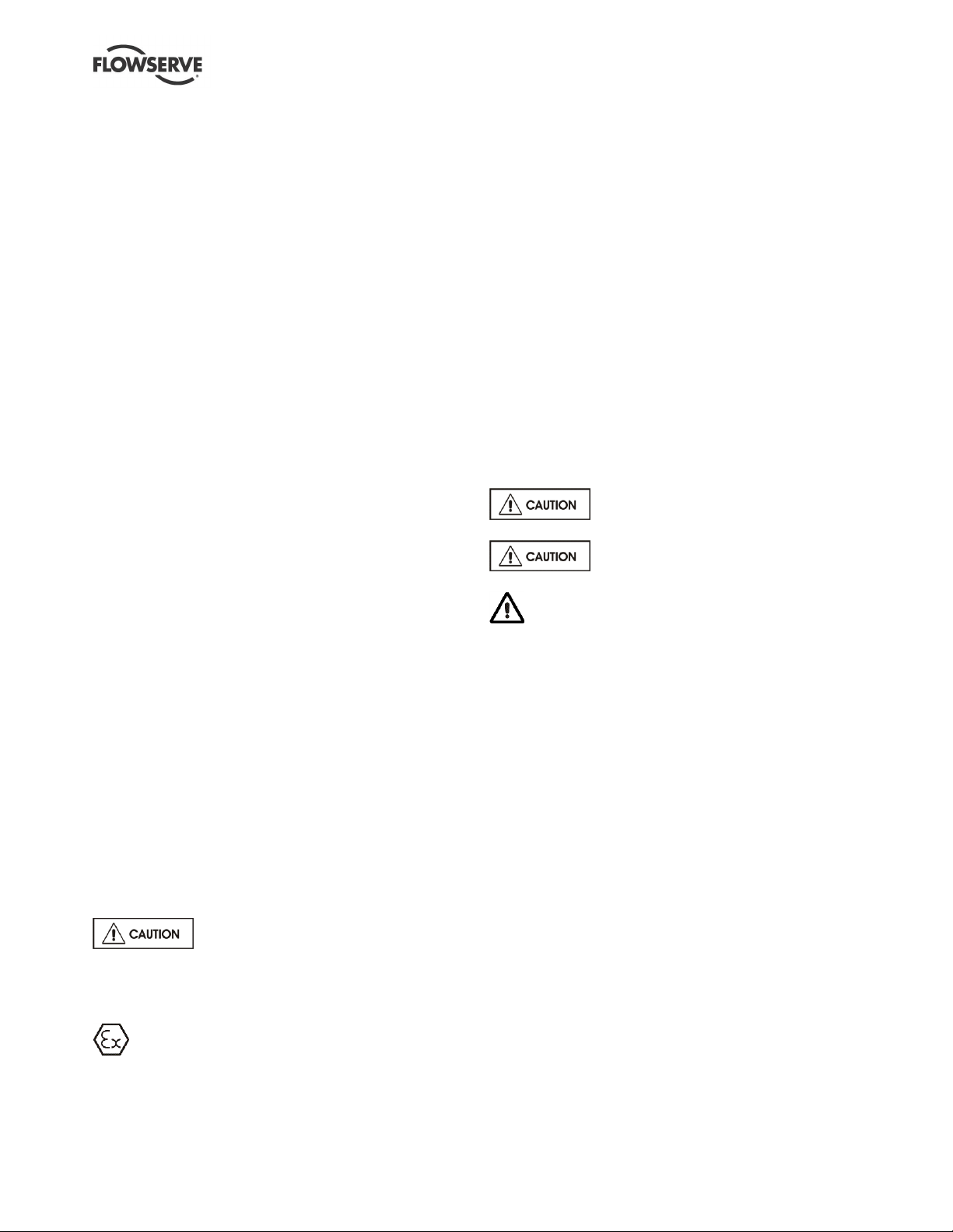
CPXV with Mark 3 ASME hydraulics ENGLISH 71569291 12-14
Shaft
Denco oiler
setting
Trico oiler
setting
Size
Dia X (mm)
Y (mm)
Z (mm)
C (mm)
1
2
3
4
24
32
42
48
14.5
16.5
17.0
13.5
21.5
23.5
24.0
20.5
12.5
14.5
15.0
11.5
X
Denco oiler
For Category 2 equipment the monitoring must create
an alarm to the plant operator or shut down the pump.
For equipment to category 1/2 or 1/3 with external flush
or filtered product flush, the flow to each line bearing
must be separately monitored and temperature sensors
fitted on each line bearing that is connected to the
pump control system. The monitoring equipment must
be suitable for the hazardous area.
For equipment to category 1/2 or 1/3 the presence of
seal barrier liquid and the temperature of the inboard
seal must both be monitored and connected to the
pump control to create an alarm signal to operators, or
to shut down the pump.
See also sections 5.8.2 to 5.8.6.
The protection sensors will generally be fitted by
Flowserve, but the connection to the pump control
system will often be by the installer of the pump.
Installers must ensure that the instructions of the
sensor manufacturer are followed, that any additional
components are suitable for the zone in which they
are to be installed, and that their trip levels are set
and checked during commissioning. The protective
systems must also be periodically checked in
accordance with the sensor manufacturer’s
instructions or with local site standards.
When clean process liquids are used to flush
bearings the user must periodically check that there
is no contamination entering the sump.
5 COMMISSIONING, START-UP,
OPERATION AND SHUTDOWN
Pump instrumentation is operational
Rotation of shaft is free when pump mechanically
and electrically isolated
5.1.1 Rolling element bearing lubrication
Determine the mode of lubrication of the pump set, eg
grease, oil, product lubrication, external clean liquid etc.
For oil lubricated pumps, fill the bearing
housing with correct grade of oil to the correct level.
These operations must be carried
out by fully qualified personnel.
Contact the factory for recommendations for
operation with pumpage of any fluid other than what the
pump was specfiically designed for.
Trico oiler option
5.1 Pre-commissioning procedure
Prior to starting the pump it is essential that the
following checks are made.
Motor properly secured to the motor stool
All fasteners tight and to the correct torque
Coupling guard is in place
Rotation check (see section 5.4.)
Impeller clearance setting
Shaft seal properly installed
Seal support system operational
Bearing lubrication
Page 17 of 44 flowserve.com
The level setting for a Trico oiler model must
be as the Trico setting in the table.
Pumps with grease lubricated antifriction bearings are
normally supplied fitted with grease nipples and with
pre-greased bearings.
Page 18

CPXV with Mark 3 ASME hydraulics ENGLISH 71569291 12-14
Shaft size
1 2 3
4
Medium duty thrust bearing duplex back-to-back AC
3306C3
3309C3
3311C3
3313C3
Heavy duty thrust bearing duplex back-to-back AC
7306 pair
7309 pair
7311 pair
7313 pair
Approximate oil fill quantities - litre (fl.oz)
0.6 (20)
0.95 (32)
1.0 (34)
0.9 (31)
Grease quantities – g (oz)
14 (0.5)
25 (0.9)
35 (1.2)
46 (1.6)
Centrifugal
pump lubrication
Oil
Splash / force feed / purge and pure **oil mist lubrication
Viscosity cSt @ 40 ºC
32
46
68
Oil temperature range *
-5 to 65 ºC
(23 to 149 ºF)
-5 to 78 ºC
(23 to 172 ºF)
-5 to 80 ºC
(23 to 176 ºF)
Designation to ISO 3448 and DIN51524 part 2
ISO VG 32
32 HLP
ISO VG 46
46 HLP
ISO VG 68
68 HLP
Oil companies and lubricants
BP Castrol †
Energol HLP-HM 32
Energol HLP-HM 46
Energol HLP-HM 68
ESSO †
NUTO HP 32
NUTO HP 46
NUTO HP 68
ELF/Total †
ELFOLNA DS 32
Azolla ZS 32
ELFOLNA DS 46
Azolla ZS 46
ELFOLNA DS 68
Azolla ZS 68
LSC (for oil mist only –
long life) †
LSO 32
(synthetic oil)
LSO 46
(synthetic oil)
LSO 68
(synthetic oil)
ExxonMobil (mineral oil) †
Mobil DTE 24
Mobil DTE 25
Mobil DTE 26
ExxonMobil (oil bath only – long life) †
Mobil SHC524
(synthetic oil) ***
Mobil SHC525
(synthetic oil)
Mobil SHC526
(synthetic oil)
Q8 †
Q8 Haydn 32
Q8 Haydn 46
Q8 Haydn 68
Shell †
Shell Tellus 32
Shell Tellus 46
Shell Tellus 68
Chevron Texaco †
Rando HD 32
Rando HD 46
Rando HD 68
Wintershall (BASF Group) †
Wiolan HS32
Wiolan HS46
Wiolan HS68
Fuchs †
Renolin CL 32
Renolin CL 46
Renolin CL 68
Grease lubricated electric motor bearings are generally
pre-greased. Refer to the motor UI for information on
the motor lubrication schedule.
Pumps with grease lubricated thrust bearings and
electric motors are supplied with pre-greased bearings.
In the case of product lubricated
bearings the source of product supply should be
checked against the order; there may be requirements
for an external clean supply, particular supply pressure
or the commencement of lubrication supply before
pump start-up.
Where the ambient is very low special lubricants are
required. If in doubt consult Flowserve for
recommendations of oil and grease types at these
lower temperatures. Where oil lubrication is utilized
and the ambient is less than -5 °C (23 °F) ensure the
ambient is no lower than 15 °C (27 °F) over the oil
pour point or use the oil class SAE 5W-50 or API-SJ
and ensure the upper operating range of the oil is
then not exceeded. Where low ambient grease has
been specially fitted this is Shell Aeroshell 22.
Approximate oil volumes are shown in section 5.2.2,
Bearing sizes and capacities.
5.2 Pump lubricants
5.2.1 Recommended rolling element bearing oil lubricants
* Note that it normally takes 2 hours for bearing temperature to stabilize and the final temperature will depend on the ambient, r/min, pumpage
temperature and pump size. Also some oils have a very low pour point and good viscosity index which extend the minimum temperature
capability of the oil. Always check the grade capability where the ambient is less than -5 ºC (23 ºF).
** If preheated pure oil mist lubrication, LCS LSO 68 or LSO 100 synthetic oils are permitted.
†
Use LSC for oil mist. Oil parameters provide flash point > 166 ºC (331 ºF), density >0.87@15 ºC (59 ºF), pour point of -10 ºC (14 ºF) or lower.
*** ExxonMobil SHC 524 synthetic oil has a pour point temperature of - 54 ºC. This oil can be used for ambient temperature as low as -50 ºC.
5.2.2 Rolling element bearing sizes and grease/oil capacities
Note: The bearing sizes do not constitute a purchasing specification.
Page 18 of 44 flowserve.com
Page 19

CPXV with Mark 3 ASME hydraulics ENGLISH 71569291 12-14
Grease
NLGI 2 *
NLGI 3
Temperature
range
-20 to +100 ºC
(-4 to +212 ºF)
-20 to +100 ºC
(-4 to +212 ºF)
Designation
acc. to DIN
KP2K-25
KP3K-20
BP
Energrease LS-EP2
Energrease LS-EP3
Elf
Multis EP2
Multis EP3
Fuchs
RENOLIT EP2
RENOLIT EP3
Esso
Beacon EP2
Beacon EP3
Mobil
Mobilux EP2
Mobilux EP3 **
Q8
Rembrandt EP2
Rembrandt EP3
Shell
Alvania EP2
Alvania EP3
Texaco
Multifak EP2
Multifak EP3
SKF
LGEP 2
5.2.3 Recommended rolling element bearing
grease lubricants
* NLGI 2 is an alternative grease and is not to be mixed with other
grades.
** Standard pre-packed grease for fitted antifriction bearings.
5.2.3.1 Food grade grease (when applicable)
NSF H1 Klubersynth UH1 64-62 is the food grade
grease option and it is NLGI grade 2.
5.2.4 Recommended fill quantities
Refer to section 5.2.2, Rolling element bearing sizes
and grease/oil capacities.
5.2.5 Lubrication schedule
5.2.5.1 Oil lubricated rolling element bearings
Normal oil change intervals are 2 000 operating hours.
For pumps on hot service or in severely damp or
corrosive atmosphere, the oil will require changing more
frequently. Lubricant and bearing temperature analysis
can be useful in optimizing lubricant change intervals.
The lubricating oil should be a high quality mineral oil
having foam inhibitors. Synthetic oils may also be
used if checks show that the rubber oil seals will not be
adversely affected.
The bearing temperature may be allowed to rise to
50 ºC (90 ºF) above ambient, but should not exceed
82 ºC (180 ºF) (API 610 limit). A continuously rising
temperature, or an abrupt rise, indicates a fault.
T5 and T6 temperature classes have more
restrictive temperature control limits, see 5.8.3.
Pumps that handle high temperature liquids may
require their bearings to be cooled to prevent bearing
temperatures exceeding their limits.
T5 and T6 temperature classes have more
restrictive temperature control limits, see 5.8.3.
5.2.5.2 Grease lubricated rolling element bearings
When grease nipples are fitted, one charge between
grease changes is advisable for most operating
conditions; ie 2 000 hours interval. Normal intervals
between grease changes are 4 000 hours or at least
every 6 months. For food grade grease the grease
change and relubrication intervals are half that of the
conventional greases.
The characteristics of the installation and severity of
service will determine the frequency of lubrication.
Lubricant and bearing temperature analysis can be
useful in optimizing lubricant change intervals.
The bearing temperature may be allowed to rise to
55 ºC (99 ºF) above ambient, but should not exceed
95 ºC (204 ºF). For most operating conditions, a
quality grease having a lithium soap base and NLGI
consistency of No 2 or No 3 is recommended. The
drop point should exceed 175 ºC (350 ºF).
T5 and T6 temperature classes have more
restrictive temperature control limits, see 5.8.3.
Never mix greases containing
different bases, thickeners or additives.
5.2.5.3 Grease lubricated plain line bearings
This option must not be used with ATEX pumps.
Pumps furnished with grease-lubricated shaft
bearings [3300] will leave the factory with lubrication
pipes [3840] shown in section 8.2, and bearings
[3300] already packed with grease. The grease used
will be of a water-resistant nature. A 120 ml (4 oz.)
minimum automatic lubricator [3800] should be
started prior to the pump start-up through their fittings
located above the pump sole plate [6140].
Grease must be insoluble in the liquid being pumped
to be effective. The recommended grease procured
with the automatic lubricators must also be
compatible to that being provided in the lubrication
lines. The normal standard default for an automatic
lubricator is Mobil Mobilith SCH100 NLGI 2 grade
grease or an equivalent, in which case the bearing
lubrication lines are filled with that grease type before
the pump leaves the factory. Check the automatic
lubricator manufacturer’s instructions provided with
the order. Consult local lubricant suppliers for the
type of grease most compatible with the liquid being
pumped.
Page 19 of 44 flowserve.com
Page 20

CPXV with Mark 3 ASME hydraulics ENGLISH 71569291 12-14
Service
Clean
Contains abrasives
Interval *
8 hours
4 – 6 hours
Location
Amount
Intermediate bearings [3020.1]
18 ml or 18 g (0.625 oz.)
per interval
Bottom bearings [3020.2]
11 ml or 11 g (0.375 oz.)
per interval
Grease lubricated line bearings require frequent
lubrication. Grease lubricating systems may be utilized.
Follow the automatic lubricator manufacturer’s
instructions for proper use. General lubrication intervals
and amounts are shown in the tables below.
* Interval depends on process conditions
Flowserve offers one system for the CPXV consisting
of individual 120 ml (4 oz.) minimum automatic
lubricators per line shaft. Consult your Flowserve
representative for additional information.
5.3 Open impeller clearance
The impeller clearance is set in the factory. This may
require adjustment because of piping attachment or
increase in temperatures. For setting instructions see
section 6.7, Setting impeller clearance.
5.4 Direction of rotation
Serious damage can result if the pump
is started or run in the wrong direction of rotation.
The pump is shipped with the coupling element
removed. Ensure the direction of rotation of the motor is
correct before fitting the coupling element. Direction of
rotation must correspond to the direction arrow.
If maintenance work has been carried
out to the site's electricity supply, the direction of
rotation should be re-checked as above in case the
supply phasing has been altered.
5.5 Guarding
Guarding is supplied fitted to the pump set.
Fasteners for guards must remain captive in the guard
to comply with the Machinery Directive 2006/42/EC.
When releasing guards, the fasteners must be
unscrewed in an appropriate way to ensure that the
fasteners remain captive.
Whenever guarding is removed or disturbed ensure
that all the protective guards are securely refitted prior
to start-up.
5.6 Priming and auxiliary supplies
5.6.1 Filling and priming
. The pump end needs to be
completely submerged in the product.
5.6.2 Auxiliary supplies
. Ensure all electrical, hydraulic,
pneumatic, sealant and lubrication systems (as
applicable) are connected and operational.
5.6.2.1 Agitation system
Where an agitation system is provided this should be
used prior to and during start up, supplied by a 23 m3/h
(100 US gpm) water inlet at 3.5 - 4 barg (50 - 60 psig).
5.6.3 Pumps fitted with a heating jacket on
molten sulphur pumps
The pump should be pre-heated for at
least one hour using steam through the heating jacket
before hot liquid is brought into the pump. The
quantity, temperature and pressure can be obtained
from the dimensional drawing. This action is
important to avoid distortion and maintain the gap
between impeller and casing.
Ensure pump is electrically isolated.
Then, before starting the driver, rotate the shaft
several times by (thermal gloved) hand to ensure
freedom of rotation as the high temperature will
cause expansion and the increase in lengths of the
components should be identical.
5.6.4 Pumps with rigid coupling on high
temperature service fitted with cooling fan and
heat sink (eg for molten salt)
These instructions already assume that any
vertical expansion bellows have been installed and
adjusted prior to installation of the pump assembly.
There are no constraints on the time
required to lower the pump into the tank but allow three
to four hours for bringing the pump unit to the required
temperature. (Minimum time required specified is
between placing the pump in place and the point of
starting the pump.) Standard safety procedures must
be followed. Pump can be installed and removed at any
liquid level; however, the spacer coupling above the
pump thrust bearing must be removed prior to this and
the impeller clearance must be wide so that the rotor
can be free to move axially in both directions.
Page 20 of 44 flowserve.com
Page 21

CPXV with Mark 3 ASME hydraulics ENGLISH 71569291 12-14
After the temperature stabalization the impeller
clearance can be reset; see section 6.7, Setting
impeller clearance.
Ensure pump is electrically isolated.
Then, before starting the driver, rotate the shaft several
times by (thermal gloved) hand to ensure freedom of
rotation as the high temperature will cause expansion at
the liquid end and the increase in lengths of the
components should be identical.
5.7 Starting the pump
a) Ensure flushing and/or
cooling/ heating liquid supplies are turned ON,
before starting pump.
b) CLOSE the outlet valve partially, but ensure that
air is allowed to escape out of the discharge pipe.
This is especially important for pumps with
product lubricated line bearings.
c) Ensure that the liquid level in
the sump is above the minimum pump casing
submergence level.
d) Ensure all vent valves are
closed before starting.
e) Start motor and check the outlet pressure.
f) If the pressure is satisfactory, SLOWLY open the
outlet valve.
5.8.1.2 Grease lubricated packed gland
(eg molten sulphur pumps)
The gland must be adjusted evenly bringing both
nuts down evenly in small steps until the lubricant leakage
is reduced as required. If no grease leakage takes place
the packing will overheat.
Grease lubricated packed gland units will be fitted with
packing greased on initial assembly. Gland nuts should
initially be finger-tight only prior to heat up. Leakage of
the lubricant should take place soon after the stuffing
box is pressurised. If no grease leakage takes place the
packing will overheat. It is important that adjustment of
the packing is even to maintain concentric alignment of
the gland ring to avoid excess temperature. If no visible
leakage takes place the packing will begin to overheat
when the pump is turning. If overheating takes place the
pump should be stopped in a controlled manner and
allowed to cool before being re-started. When the pump
is re-started, check to ensure leakage is taking place at
the packed gland.
Care must be taken when adjusting the gland
on an operating pump. Safety gloves are essential.
Loose clothing must not be worn to avoid being
caught up by the pump shaft. Shaft guards must be
replaced after the gland adjustment is complete.
5.8.1.3 Liquid lubricated packed gland
g) . Do not run the pump with the
outlet valve completely closed.
h) If NO pressure, or LOW pressure, STOP the pump.
Refer to section 7, Faults; causes and remedies for
fault diagnosis.
5.8 Running the pump
5.8.1 Pumps fitted with packed gland
Never run gland packing dry, even for
a short time.
5.8.1.1 Nitrogen lubricated packed gland
(eg molten salt pumps)
Pumps for high temperature molten salt utilize special
metal gland packing rings cooled and lubricated only
by nitrogen gas. The nitrogen injection flow rate should
be monitored periodically after initial stuffing box
adjustment to maintain the flow rate advised on the
general arrangement drawing.
On molten salt service that uses metal gland
packing rings, the packing is not to be adjusted while
the pump is in operation.
The gland must be adjusted evenly bringing both
nuts down evenly in small steps until the lubricant leakage
is reduced as required. If no grease leakage takes place
the packing will overheat.
Where liquid is permitted for a low temperature pump
gland packing lubricant, the liquid must be a safe liquid,
in which case there must be some visible leakage from
the gland. Gland nuts should initially be finger-tight
only prior to heat up. Leakage of the lubricant should
take place soon after the stuffing box is pressurised.
The pump should be run for 30 minutes with steady
leakage and the gland nuts tightened by 10 degrees at
a time until leakage is reduced to an acceptable level.
Bedding in of the packing may take another 30
minutes. It may be necessary to slacken the gland
nuts to achieve leakage on this type of non-metal
packing arrangement. It is important that adjustment of
the packing is even to maintain concentric alignment of
the gland ring to avoid excess temperature. If no
visible leakage takes place the packing will begin to
overheat when the pump is turning. If overheating
takes place the pump should be stopped in a controlled
manner and allowed to cool before being re-started.
Page 21 of 44 flowserve.com
Page 22

CPXV with Mark 3 ASME hydraulics ENGLISH 71569291 12-14
Pump frame size
Normal flow Qn
l/min (USgpm)
Critical flow Q
c
l/min (USgpm
1
4.2 (1.2)
3.6 (1)
2
5 (1.4)
4.3 (1.2)
3
5.9 (1.6)
5 (1.4)
4
6.7 (1.8)
5.7 (1.5)
Vibration velocity – unfiltered mm/s (in./sec) r.m.s.
Normal N
7.1 (0.28)
Alarm N x 1.25
9.0 (0.35)
Shutdown trip N x 2.0
14.2 (0.56)
When the pump is re-started, check to ensure leakage
is taking place at the packed gland.
Care must be taken when adjusting the gland
on an operating pump. Safety gloves are essential.
Loose clothing must not be worn to avoid being
caught up by the pump shaft. Shaft guards must be
replaced after the gland adjustment is complete.
5.8.2 Pumps fitted with mechanical seals
Mechanical seals require no adjustment. Any slight
initial leakage will stop when the seal is run in.
Before pumping dirty liquids it is advisable, if
possible, to run the pump in using clean liquid to
safeguard the seal face.
External flush or quench shall be started
before the pump is run and allowed to flow for a period
after the pump has stopped.
5.8.3 Thrust bearings
If the pumps are working in a potentially explosive
atmosphere without regular monitoring, temperature
monitoring of the thrust bearing is recommended. For
temperature classes T5 and T6 thrust bearing
monitoring must be fitted.
If the thrust bearing temperatures are to be monitored it
is essential that a benchmark temperature is recorded
at the commissioning stage and after the bearing
temperature has stabilized.
Record the bearing temperature (t) and the
ambient temperature (ta)
Estimate the likely maximum ambient
temperature (tb)
Set the alarm at (t+tb-ta+5) ºC (t+tb-ta+10 ºF)
and the trip at 100 ºC (212 ºF) for oil lubrication
and 105 ºC (220 ºF) for grease lubrication.
Ensure that the ATEX temperature class limit is
not exceeded if the pump is operating in a
hazardous area. The normal bearing
temperature Tn is = t+tb-ta where Tn<Tc. In the
case of T5 and T6, the critical bearing
temperature Tc = 65 oC (T6) or 80 oC (T5)
It is important, particularly with grease lubrication, to
keep a check on bearing temperatures. After start-up
the temperature rise should be gradual, reaching a
maximum after approximately 1.5 to 2 hours. This
temperature rise should then remain constant or
marginally reduce with time. (Refer to section 5.2.5
for further information.)
5.8.4 Line bearing temperature
When pump are equipped for
monitoring of line bearing temperature the normal
and shut off levels must be set to:
The normal bearing temperature Tn is the flush
line maximum liquid temperature +5 °C (+9 °F)
The critical bearing temperature Tc is set to
applicable ATEX class limit -10 °C (-18 °F).
(See table in section 1.6.4.3.)
If the measured bearing temperature exceeds the Tc
value the system must give an alarm to the pump
operator or the pump must be automatically stopped
and the cause investigated before restarting the pump.
5.8.5 Line bearing lubrication
For pumps equipped with flow
monitor for the individual line bearings, the bearing
flush to each line bearing shall be controlled
according the following table:
For bearing frame size see section 8.7 first column.
If either line bearing flush is reduced to below the Qc
values the pump must be stopped and the cause
investigated.
5.8.6 Normal vibration levels, alarm and trip
For guidance, pumps generally fall under a
classification for rigid support machines within the
International rotating machinery standards and the
recommended maximum levels below are based on
those standards.
Regular monitoring of the pump
vibration is recommended to show any deterioration in
pump or system operating conditions. The vibration is
measured adjacent to the pump thrust bearing.
Alarm and trip values for installed pumps
should be based on the actual measurements (N) taken
on the pump in the fully commissioned as new condition.
For remote installations continuous monitoring and
automatic alert and shutdown is recommended.
Page 22 of 44 flowserve.com
Page 23

CPXV with Mark 3 ASME hydraulics ENGLISH 71569291 12-14
Motor rating kW (hp)
Maximum stop/starts
per hour
Up to 15 (20)
15
Between 15 (20) and 90 (120)
10
Above 90 (120)
6
Where pumps operate in a hazardous area
refer to section 1.6.4.3 and 4.7 for the requirements
for monitoring and protective systems.
5.8.7 Shaft seal at sole plate
Seal maximum temperature to be defined by seal
vendor for that specific application.
5.8.8 Stop/start frequency
Pump sets are normally suitable for the number of
equally spaced stop/starts per hour shown in the
table below. Check capability of the driver and
control/starting system before commissioning.
Where duty and standby pumps are installed it is
recommended that they are run alternately every week.
5.9 Stopping and shutdown
a) Close the outlet valve, but ensure
that the pump runs in this condition for no more
than a few seconds.
b) Stop the pump.
c) After stopping a jacketed pump,
leave the steam supply on for approximately 20
minutes. Keep steam circulating in stand-by
pumps.
d) Switch off flushing and/or cooling/heating liquid
supplies at a time appropriate to the process.
e) For prolonged shut-downs and
especially when ambient temperatures are likely to
drop below freezing point, the pump and any
cooling and flushing arrangements must be drained
or otherwise protected.
5.10 Hydraulic, mechanical and electrical
duty
This product has been supplied to meet the
performance specifications of your purchase order,
however it is understood that during the life of the
product these may change. The following notes may
help the user decide how to evaluate the implications
of any change. If in doubt contact your nearest
Flowserve office.
5.10.1 Specific gravity (SG)
Pump capacity and total head in metres (feet) do not
change with SG, however pressure displayed on a
pressure gauge is directly proportional to SG.
Power absorbed is also directly proportional to SG. It
is therefore important to check that any change in SG
will not overload the pump driver or over-pressurize
the pump.
5.10.2 Viscosity
For a given flow rate the total head reduces with
increased viscosity and increases with reduced
viscosity. Also for a given flow rate the power
absorbed increases with increased viscosity, and
reduces with reduced viscosity. It is important that
checks are made with your nearest Flowserve office if
changes in viscosity are planned.
5.10.3 Pump speed
Changing pump speed effects flow, total head, power
absorbed, NPSHR, noise and vibration. Flow varies
in direct proportion to pump speed, head varies as
speed ratio squared and power varies as speed ratio
cubed. The new duty, however, will also be
dependent on the system curve. If increasing the
speed, it is important therefore to ensure the
maximum pump working pressure and critical shaft
speed are not exceeded, the driver is not overloaded,
NPSHA > NPSHR, and that noise and vibration are
within local requirements and regulations.
5.10.4 Net positive suction head (NPSHA)
NPSH available (NPSHA) is a measure of the head
available in the pumped liquid, above its vapor
pressure, at the pump suction branch.
NPSH required (NPSHR) is a measure of the head
required in the pumped liquid, above its vapor pressure,
to prevent the pump from cavitating.
It is important that NPSHA > NPSHR. The margin
between NPSHA > NPSHR should be as large as
possible.
If any change in NPSHA is proposed, ensure these
margins are not significantly eroded. Refer to the
pump performance curve to determine exact
requirements particularly if flow has changed.
If in doubt please consult your nearest Flowserve
office for advice and details of the minimum allowable
margin for your application.
Page 23 of 44 flowserve.com
Page 24

CPXV with Mark 3 ASME hydraulics ENGLISH 71569291 12-14
5.10.5 Pumped flow
Flow must not fall outside the minimum and maximum
continuous safe flow shown on the pump performance
curve and or data sheet.
6 MAINTENANCE
6.1 General
It is the plant operator's responsibility to ensure
that all maintenance, inspection and assembly work
is carried out by authorized and qualified personnel
who have adequately familiarized themselves with
the subject matter by studying this manual in detail.
(See also section 1.6.)
Any work on the machine must be performed when it
is at a standstill. It is imperative that the procedure
for shutting down the machine is followed, as
described in section 5.9.
Guard fasteners must remain captive during
dismantling of guards, as described in section 5.5.
On completion of work all guards and safety devices
must be re-installed and made operative again.
Before restarting the machine, the relevant
instructions listed in section 5, Commissioning, start
up, operation and shut down, must be observed.
Oil and grease leaks may make the ground
slippery. Machine maintenance must always
begin and finish by cleaning the ground and the
exterior of the machine.
If platforms, stairs and guard rails are required for
maintenance, they must be placed for easy access to
areas where maintenance and inspection are to be
carried out. The positioning of these accessories
must not limit access or hinder the lifting of the part to
be serviced.
When air or compressed inert gas is used in the
maintenance process, the operator and anyone in the
vicinity must be careful and have the appropriate
protection.
Do not spray air or compressed inert gas on skin.
Do not direct an air or gas jet towards other people.
Never use air or compressed inert gas to clean clothes.
Before working on the pump, take measures to
prevent an uncontrolled start. Put a warning board
on the starting device with the words:
"Machine under repair: do not start".
With electric drive equipment, lock the main switch
open and withdraw any fuses. Put a warning board
on the fuse box or main switch with the words:
"Machine under repair: do not connect".
Never clean equipment with inflammable solvents or
carbon tetrachloride. Protect yourself against toxic
fumes when using cleaning agents.
6.2 Maintenance schedule
It is recommended that a maintenance plan
and schedule is adopted, in line with these User
Instructions, to include the following:
a) Any auxiliary systems installed must be monitored,
if necessary, to ensure they function correctly.
b) Gland packings must be adjusted correctly to
give visible leakage and concentric alignment of
the gland follower to prevent excessive
temperature of the packing or follower.
c) Check for any leaks from gaskets and seals.
The correct functioning of the shaft seal must be
checked regularly.
d) Check bearing lubricant level, and if the hours
run show a lubricant change is required.
e) Check that the duty condition is in the safe
operating range for the pump.
f) Check vibration, noise level and surface
temperature at the bearings to confirm
satisfactory operation.
g) Check dirt and dust is removed from areas around
close clearances, bearing housings and motors.
h) Check coupling alignment and re-align if necessary.
Our specialist service personnel can help with
preventative maintenance records and provide
condition monitoring for temperature and vibration to
identify the onset of potential problems.
If any problems are found the following sequence of
actions should take place:
a) Refer to section 7, Faults; causes and remedies,
for fault diagnosis.
b) Ensure equipment complies with the
recommendations in this manual.
c) Contact Flowserve if the problem persists.
Page 24 of 44 flowserve.com
Page 25

CPXV with Mark 3 ASME hydraulics ENGLISH 71569291 12-14
6.2.1 Routine inspection (daily/weekly)
The following checks should be made
and the appropriate action taken to remedy any
deviations:
a) Check operating behaviour. Ensure noise,
vibration and bearing temperatures are normal.
b) Check that there are no abnormal fluid or
lubricant leaks (static and dynamic seals) and
that any sealant systems (if fitted) are full and
operating normally.
c) Check that shaft seal leaks are within acceptable
limits.
d) Check the level and condition of oil lubricant.
On grease lubricated pumps, check running
hours since last recharge of grease or complete
grease change.
e) Check any auxiliary supplies eg heating/cooling
(if fitted) are functioning correctly.
Refer to the manuals of any associated
equipment for routine checks needed.
6.2.2 Periodic inspection (six monthly)
a) Check foundation bolts for
security of attachment and corrosion.
b) Check pump running records for hourly usage to
determine if bearing lubricant requires changing.
c) The coupling should be checked for correct
alignment and worn driving elements.
Refer to the manuals of any associated
equipment for periodic checks needed.
6.2.3 Re-lubrication
For general guidelines refer to section 5.2.5,
Lubrication schedule.
Lubricant and bearing temperature analysis can be
useful in optimizing lubricant change intervals.
6.2.4 Mechanical seals
When leakage becomes unacceptable the seal will
need replacement.
6.2.5 Gland packing
Occasionally, a new ring of packing will be required to
keep the box full.
On jacketed molten sulphur pumps the stuffing box is
normally supplied with a lantern ring to enable it to be
lubricated to the centre of the packing with the required
Molykote 44 Medium or equivalent grease from a
Staufer or equivalent.
6.3 Spare parts
6.3.1 Ordering of spares
Flowserve keeps records of all pumps that have been
supplied. When ordering spares the following
information should be quoted.
1) Pump serial number.
2) Pump size.
3) Part name – taken from section 8.
4) Part number – taken from section 8.
5) Number of parts required.
The pump size and serial number are shown on the
pump nameplate.
To ensure continued satisfactory operation,
replacement parts to the original design specification
should be obtained from Flowserve. Any change to
the original design specification (modification or use
of a non-standard part) will invalidate the pump’s
safety certification.
6.3.2 Storage of spares
Spares should be stored in a clean dry area away
from vibration. Inspection and re-treatment of
metallic surfaces (if necessary) with preservative is
recommended at 6 monthly intervals.
Pump must be stopped and
electrically isolated when replacing gland packing.
There is a fan above the packing, close by, on all
high temperature builds of the pump.
On hot molten salt service nitrogen is fed with three
rings of metal packing and Nitrogen will leak across the
packing for cooling purposes.
Page 25 of 44 flowserve.com
Page 26

CPXV with Mark 3 ASME hydraulics ENGLISH 71569291 12-14
Part
no.
Designation
Number of pumps
(including stand-by)
2 3 4 5 6/7
8/9
10(+)
2100
Shaft 1 2
3
30%
2200
Impeller 1 2 3 30%
2400.1
Shaft sleeve pump end
2 3 4
50%
3013
Bearing - thrust
1 2 3 4 50%
3300.1
Bearing - pump end
1 2 3 4 50%
3300.2
Bearing - lineshaft #
1 2 3 4 50%
3400.1
Shaft sleeve intermediate #
2 3 4
50%
3712
Bearing nut
1 2 3 4 50%
4120
Lantern halves #
1 2 3
30%
4130
Gland packing complete set #
2 3 4
40%
4200
Mechanical seals #
1 2 3
30%
2400.2
Sleeve mechanical seal #
2 3 4
50%
4305
Lip seal #
4 6 8 9 10
100%
6570.9
Shaft sleeve screw
for 3400.1 #
2 3 4
50%
4590.1 *
Pump casing
gasket
4 6 8 9 12
150%
4590.2
Discharge flange
gasket
4 6 8 9 12
150%
4610.1
O-ring impeller
4 6 8 9 12
150%
4610.2
O-ring carrier
2 3 4
50%
4610.3
O-ring mechanical
seal sleeve #
2 3 4
50%
-
Power end
- - - - - 1 2
Fastener
Screw size
Torque Nm (lbf•ft)
All except where
otherwise stated
M8
M10
M12
M16
M20
16 (12)
25 (18)
35 (26)
80 (59)
130 (96)
Item
Description
Group 1
Group 2
Group 3
[6572.2]
Plain bearing
carrier studs
⅜ in. –
16 Nm
(12 lbf•ft)
⅜ in. –
16 Nm
(12 lbf•ft)
½ in. –
54 Nm
(40 lbf•ft)
½ in. –
41 Nm
(30 lbf•ft)
[6570.1]
Casing
screws
½ in. –
41 Nm
(30 lbf•ft)
½ in. –
41 Nm
(30 lbf•ft)
⅝ in. –
81 Nm
(60 lbf•ft)
¾ in. –
136 Nm
(100 lbf•ft)
⅞ in. –
217 Nm
(160 lbf•ft)
[6572.3]
Bearing cover
screws
⅜ in. –
27 Nm
(20 lbf•ft)
⅜ in. –
27 Nm
(20 lbf•ft)
½ in. –
54 Nm
(40 lbf•ft)
6.4 Recommended spares
(For two years operation - as per VDMA 24296)
# When required due to fitting as part of the original build specification.
6.5 Tools required
A typical range of tools that will be required to
maintain these pumps is listed below.
Readily available in standard tool kits, and dependent
on pump size – standard SAE hand tools for ASME
wet end hydraulics:
Hand wrenches
Socket wrenches
Open ended spanners (wrenches) to suit up to
M 48 screws/nuts
Socket spanners (wrenches), up to M 48 screws
Allen keys, up to 10 mm (A/F)
Range of screwdrivers
Soft mallet
More specialized equipment:
Bearing pullers
Bearing induction heater
Dial test indicator
C-spanner (wrench) - for removing shaft nut.
(If difficulties in sourcing are encountered, consult
Flowserve.)
6.6 Casing, seal housing and fastener
torques
Standard SAE fasteners for ASME wet end
hydraulics:
Notes:
1. For non-lubricated/coated threads, add 25 % to the values
given above.
2. Gasket joint torque values are for unfilled PTFE gaskets. Other
gasket materials may require additional torque to seal.
Exceeding metal joint torque values is not recommended.
Above apply for applications below
250 ºC only and not in the range 250 ºC to 600 ºC.
Below lower values apply for
applications in the high temperature range of 250 ºC to
600 ºC.
Non-metallic gaskets incur creep
relaxation - before commissioning the pump check
and retighten fasteners to tightening torques stated.
For the tightening sequence also refer to good
industry practice. See section 10.3, Reference 6, for
more detail.
Page 26 of 44 flowserve.com
Page 27

CPXV with Mark 3 ASME hydraulics ENGLISH 71569291 12-14
Thread data
Material group
A
316 SS
B
ASTM A193
Grade B7M
4140 Steel
C
ASTM A193
Grade B8C
347H SS
Approximate yield stress N/mm2 (psi)
Nominal
diameter
mm (in.)
Threads
per
25 mm
(1 in.)
207
(30 000)
(<400 ºC)
552
(80 000)
(<400 ºC)
138
(20 000)
(400 to
600 ºC)
Torque Nm (lb•ft)
6 (0.25)
20
4 (3)
9 (7)
3 (2)
8 (0.31)
18
7 (5)
17 (13)
5 (3)
10 (0.37)
16
9 (7)
27 (20)
8 (6)
11 (0.43)
14
16 (12)
42 (31)
15 (11)
12 (0.5)
13
23 (17)
62 (46)
20 (15)
15 (0.56)
12
27 (20)
89 (66)
27 (20)
16 (0.62)
11
41 (30)
118 (87)
37 (27)
19 (0.74)
10
81 (60)
203 (150)
60 (44)
22 (0.87)
9
122 (90)
312 (250)
95 (70)
25 (1.00)
8
190 (140)
488 (360)
151 (111)
29 (1.13)
7
271 (200)
705 (520)
236 (174)
29 (1.13)
8
271 (200)
732 (540)
218 (161)
32 (1.25)
7
366 (270)
990 (730)
336 (248)
32 (1.25)
8
379 (280)
1 017 (750)
309 (228)
35 (1.38)
6
434 (320)
1 140 (840)
445 (328)
35 (1.38)
8
461 (340)
1 221 (900)
418 (308)
38 (1.50)
6
556 (410)
1 506 (1 110)
536 (395)
38 (1.50)
8
597 (440)
1 587 (1 170)
491 (362)
41 (1.63)
5.5
719 (530)
1 927 (1 420)
482 (355)
41 (1.63)
8
773 (570)
2 076 (1 530)
518 (382)
44 (1.75)
5
882 (650)
2 375 (1 750)
945 (697)
44 (1.75)
8
971 (720)
2 592 (1 910)
909 (670)
50 (2.00)
4.5
1 356 (1 000)
1 363 (1 005)
50 (2.00)
8
1 478 (1 090)
1 336 (985)
57 (2.25)
8
2 143 (1 580)
63 (2.50)
8
2 970 (2 190)
Temperature
Impeller clearance setting
(RV and OP impeller)
All impeller diameters
50 ºC (120 ºF)
100 ºC (210 ºF)
150 ºC (300 ºF)
200 ºC (390 ºF)
260 ºC (500 ºF)
0.45 mm (0.018 in.)
0.55 mm (0.022 in.)
0.65 mm (0.026 in.)
0.75 mm (0.030 in.)
0.85 mm (0.033 in.)
Reverse vane
impeller rear
clearance
Bolt torque values for class 2 lubricated threads
6.7 Setting impeller clearance
This procedure may be required after the pump has
been dismantled or a different clearance is required.
6.7.1 Setting reverse vane impeller
For the Mark 3 reverse vane (RV) impeller the rear
clearance setting is as shown in the table below.
a) Before carrying out this procedure ensure that
any mechanical seal(s) [4200] fitted can tolerate
a change in their axial setting, otherwise it will be
necessary to dismantle the unit and reset the seal
axial position after adjusting the impeller
clearance.
b) Disconnect the coupling if it has limited axial
flexibility.
c) Record the gap between the bearing carrier [3240]
and stool [3160] using feeler gauges.
Some mechanical seal types may be
impaired if moved more than 0.5 mm (0.02 in.) from
their nominal setting.
d) Loosen the bearing carrier screws [6570.8] and
tighten the bearing carrier using jacking screws
[6570.7].
e) Ensure the carrier jacking screws [6570.7] are
tightened evenly so as to draw the bearing carrier
away from the sole plate, until the impeller just
contacts the plain bearing carrier [3245]. Turn the
shaft [2100] during this procedure until a detectable
rub is obtained. This is the zero clearance position.
The shaft must be turned in the direction indicated
on the casing and sole plate.
f) Set a dial indicator to zero on the shaft end or
measure the bearing carrier [3240] to motor
pedestal [3160] gap and record the
measurement.
g) Ensure carrier screws [6570.8] are still slack and
slacken off the bearing carrier jacking screws
[6570.7] evenly (about one flat at a time) until the dial
indicator or feeler gauge shows the correct impeller
clearance from the zero clearance position. This
clearance should be between 0.45 and 0.85 mm
(0.018 and 0.033 in.) depending on the temperature
of the pumped fluid, as in the table above.
h) Evenly tighten the bearing carrier screws [6570.8]
keeping the dial indicator or feeler gauges
reading the correct setting. Then tighten the
hexagon nuts [6580.5] to lock the jacking screws
[6570.7] in position.
i) Compare the original and final gaps between the
bearing carrier and sole plate to check if the
movement of the shaft has exceeded the
mechanical seal capability (over/under compression
of the seal). Re-position the seal to correct this.
Page 27 of 44 flowserve.com
Page 28

CPXV with Mark 3 ASME hydraulics ENGLISH 71569291 12-14
Temperature
Impeller clearance setting
(RV and OP impeller)
All impeller diameters
50 ºC (120 ºF)
100 ºC (210 ºF)
150 ºC (300 ºF)
200 ºC (390 ºF)
260 ºC (500 ºF)
0.45 mm (0.018 in.)
0.55 mm (0.022 in.)
0.65 mm (0.026 in.)
0.75 mm (0.030 in.)
0.85 mm (0.033 in.)
Bearing sleeve size
mm (in.)
Sleeve
diameter/tolerance
min diam - max diam
mm (in.)
Bearing clearance
(max/min)
mm (in.)
Fr1/2 silicon carbide
54 (2.125)
53.87
(2.1209)
53.89
(2.1217)
0.13/0.085
(0.0051/0.0033)
Fr3/4 silicon carbide
79 (3.110)
78.85
(3.1043)
78.87
(3.1051)
0.18/0.13
(0.0071/0.0051)
Fr1 pump end bush in
engineering polymer
35 (1.375)
34.98
(1.3772)
35.00
(1.3780)
0.31/0.15
(0.0122/0.0059)
Fr1 intermediate and Fr2
pump end bushes in
engineering polymer
45 (1.770)
44.98
(1.7709)
45.00
(1.7717)
0.35/0.19
(0.0138/0.0075)
Fr3 pump end bush in
engineering polymer
65 (2.559)
64.98
(2.5583)
65.00
(2.5591)
0.41/0.25
(0.0161/0.0098)
Fr2/3 intermediate
bushes in engineering
polymer
65 (2.559)
64.98
(2.5583)
65.00
(2.5591)
0.39/0.23
(0.0154/0.0091)
Fr4 pump end and
intermediate bush in
engineering polymer
70 (2.7559)
69.98
(2.5583)
70.00
(2.7559)
0.39/0.23
(0.0154/0.0091)
j) Check that the shaft can turn freely without binding.
k) If a cartridge seal is fitted, reset it at this point.
l) Ensure the coupling distance between shaft ends
(DBSE) is correct. Reset/re-align if necessary.
6.7.2 Setting open impeller
For the Mark 3 open (OP) impeller the rear clearance
setting is as shown in the table below.
a) Before carrying out this procedure on the CPXV
ensure that any mechanical seal(s) fitted can
tolerate a change in its axial setting, otherwise it
will be necessary to dismantle the unit and reset
the seal axial position after adjusting the impeller
clearance.
b) Disconnect the coupling if it has limited axial
flexibility.
c) Record the gap between the bearing carrier [3240]
and stool [3160] using feeler gauges.
clearance from the zero clearance position. This
clearance should be between 0.45 and 0.85 mm
(0.018 and 0.033 in.) depending on the temperature
of the pumped fluid, as in the table above.
h) Evenly tighten the bearing carrier screws [6570.8]
keeping the dial indicator or feeler gauges reading
the correct setting. Then tighten the hexagon nuts
[6580.5] to lock the jacking screws [6570.7] in
position.
i) Compare the original and final gaps between the
bearing carrier and sole plate to check if the
movement of the shaft has exceeded the
mechanical seal capability (over/under compression
of the seal). Re -position the seal to correct this.
j) Check that the shaft can turn freely without binding.
k) If a cartridge seal is fitted, reset it at this point.
l) Ensure the coupling distance between shaft ends
(DBSE) is correct. Reset/re-align if necessary.
6.8 Renewal clearances
As wear takes place between the impeller and casing
ring the overall efficiency of the pump set will
decrease. To maintain optimum efficiency it is
recommended that the clearances shown in section
6.7, Setting impeller clearance, are maintained.
On product lubricated bearings it is recommended
that these are renewed at the diametrical clearance in
the as fitted condition stated in the following table:
impaired if moved more than 0.5 mm (0.02 in.)
from their nominal setting.
d) Loosen the bearing carrier screws [6570.8] and
slacken off the bearing carrier using screws [6570.7].
e) Ensure the carrier jacking screws [6570.7] are
slackened off evenly so as to draw the bearing
carrier towards the sole plate, until the impeller just
contacts the pump casing. Turn the shaft [2100]
during this procedure until a detectable rub is
obtained. This is the zero clearance position. The
shaft must be turned in the direction indicated on
the casing and sole plate.
f) Set a dial indicator to zero on the shaft end or
measure the bearing carrier [3240] to motor
pedestal [3160] gap and record the measurement.
g) Ensure carrier screws [6570.8] are still slack and
tighten the bearing carrier jacking screws [6570.7]
evenly (about one flat at a time) until the dial
indicator or feeler gauge shows the correct impeller
Page 28 of 44 flowserve.com
Some mechanical seal types may be
Page 29

CPXV with Mark 3 ASME hydraulics ENGLISH 71569291 12-14
6.9 Disassembly
Refer to Safety section before dismantling the
pump.
For pumps with heating jackets, ensure that the
pump is cooled down correctly and sufficiently before
handling. After evacuating the tank and shutting off
the pump, the pumped liquid flows down through the
pump into the sump. After approximately 30 minutes
the heating steam line should be closed.
Before dismantling the pump for
overhaul, ensure genuine Flowserve replacement
parts are available.
Refer to sectional drawings for part numbers and
identification. See section 8, Parts lists and drawings.
6.9.1 Pump disassembly
a) Disconnect all auxiliary pipes and tubes where
applicable.
b) Disconnect all discharge and auxiliary pipework.
c) Remove coupling guard, disconnect coupling and
remove motor.
d) If oil lubricated unit, drain oil.
e) Remove nuts securing sole plate to foundations
and lift the complete unit clear.
f) Record the gap between bearing carrier and sole
plate so that this setting can be used during
workshop assembly.
g) Remove suction pipe and/or strainer if fitted.
h) Remove all flushing lines as appropriate, casing
screws and discharge flange bolts.
i) Remove pump casing.
j) Remove pump casing and discharge flange
gaskets and discard. (A replacement gasket will
be required for assembly.)
k) Clean the gasket mating surfaces.
6.9.2 Impeller removal (threaded on impeller)
NEVER APPLY HEAT TO REMOVE THE
IMPELLER. TRAPPED OIL OR LUBRICANT MAY
CAUSE AN EXPLOSION
a) Fit a chain wrench or bolt a bar to the holes in the
coupling half, or fit a keyed shaft wrench directly
to the shaft.
b) Wearing metal mesh reinforced gloves, rotate the
shaft [2100] by turning the impeller [2200]
clockwise as viewed from the impeller end of the
shaft, so that the wrench makes contact with one
of the supports of the motor pedestal [3160].
c) Give the impeller a quick turn counter-clockwise
so that the wrench handle strikes the other side
of the window edge of the motor pedestal [3160].
A few sharp strikes will loosen one of the shaft
threads. If at this point the impeller is still firmly
threaded to the pump end shaft [2100], then
check in the windows in column pipe above each
inter bearing to see where the threads have
started to disengage.
d) If the impeller is loose then unscrew it and
discard the impeller O-ring [4610.1]. Use a new
O-ring for assembly.
e) In case the shaft starts to disengage at another
thread. Loosen screws and nuts [6570.5 and
6580.1] to disconnect the discharge pipe [1360]
from the pump casing [1100].
f) Ensure both sections of the support column are
well supported. Unscrew the screw and nut
[6570.11 and 6580.2] at the loose joint, and
disengage the lubrication pipe [3840]. Unscrew
the shaft [2100s] taking great care to support
both shaft ends when they disengage to avoid
damaging the line bearings.
g) Remove the lower section of the support column
and place on a level support structure.
h) If the support column contains at least one inter
bearing, remove the highest column pipe section by
removing the screw and nut [6570.11 and 6580.2]
and the lubrication pipe [3840]. Then slide the
support pipe and line bearing assembly over the
shaft while ensuring the shaft is well supported.
Remove the free section of shaft [2100]. Repeat
the above until only the lowest section of the
support column pipe [1350] remains.
i) Fix the lowest section of the support column on a
workbench. Fit a spanner to the flats of the
upper end of the shaft and ensure it can not slip.
j) Fit a strap wrench around the impeller and spin
the impeller clockwise to lift the spanner from the
work bench.
k) Spin the impeller quickly counter-clockwise with
the wrench to get the spanner to make impact on
the workbench or a wooden block. The impact
will loosen the impeller.
l) Unscrew the impeller and discard the impeller
O-ring [4610.1]. Use a new O-ring for assembly.
6.9.3 Support columns, shafts and bearings
a) Remove the two screws which fix the lower
bearing carrier to the lower support column.
b) Remove the lower bearing carrier.
If silicon carbide, carbon or high graphite
iron bearings are fitted extreme care should be taken
to avoid chipping or cracking these relatively brittle
components.
c) Unbolt and remove support column(s).
d) Unscrew the overhanging shaft section prior to
removing the next section of support column.
Page 29 of 44 flowserve.com
Page 30

CPXV with Mark 3 ASME hydraulics ENGLISH 71569291 12-14
e) Any long length of shaft should be temporarily
supported to avoid bending or damage whilst
removing the muff coupling(s).
6.9.4 Bearings, seals and upper shaft
a) If a seal is fitted in the sole plate, determine its type
and remove the seal cover screws and any
accessible seal to shaft clamp screws as appropriate.
b) Remove the bearing housing screws.
c) Drive out the labyrinth disk from the sole plate
(if fitted).
d) Pull the bearing housing and upper shaft assembly
out of the sole plate. Take care to support the long
shaft to avoid bending or damage to it and any
attached components.
e) Pull off the coupling and remove the coupling key.
f) Unscrew the bearing outer nut (left hand thread).
g) Remove the drive side flinger and or labyrinth seal
(if fitted) from the shaft.
h) Slide the bearing carrier off of the bearing(s).
i) Remove the bearing nut.
j) Pull off the bearing(s).
k) Loosen any remaining seal to shaft clamp screws
and slide the seal(s) and seal covers off the shaft.
Any bearings or sleeves can then be pressed out/off
as required after first removing any retaining screws.
6.10 Examination of parts
Used parts must be inspected before
assembly to ensure the pump will subsequently run
properly. In particular, fault diagnosis is essential to
enhance pump and plant reliability.
6.10.1 Casing, seal housing and impeller
Inspect for excessive wear, pitting, corrosion, erosion
or damage and any sealing surface irregularities.
Replace as necessary.
6.10.2 Shaft and sleeve (if fitted)
Obtain and fit a new shaft or sleeve if grooved, pitted
or worn.
6.10.4 Gaskets and O-rings
After dismantling, discard and replace.
6.10.5 Bearings
It is recommended that bearings are not re-used after
any removal from the shaft.
The plain bearings may be re-used if both the bearing
bush and bearing sleeve show no sign of wear, grooving
or corrosion attack. It is recommended that both the
bush and sleeve are replaced at the same time.
6.11 Assembly
To assemble the pump consult the sectional
drawings. See section 8, Parts lists and drawings.
Ensure threads, gasket and O-ring mating faces are
clean. Apply thread sealant to non-face sealing pipe
thread fittings.
6.11.1 Mechanical seal or gland packing seal
(If there is no mechanical seal or gland packing at the
sole plate, go to section 6.11.2, Thrust bearing carrier
and shaft sub-assembly.)
Where a mechanical seal is used, extreme cleanliness
is required during assembly. In many instances a preassembled cartridge seal will be used. Where this is not
the case the sealing faces must be checked to be free
from scratches or other damage.
a) Use olive oil for fitting elastomers.
b) Where an anti-rotation pin is fitted ensure that
correct engagement with the slot is achieved.
c) Carefully press stationary mechanical seal seat(s)
into their housing such that these are not deformed
or damaged.
Work to the specific manufacturer’s
instructions for the mechanical seal.
Where a packed stuffing box [4110] is fitted, pack the
stuffing box cover before fitting on to the shaft, as
follows:
a) Position each ring [4130] into the box individually,
evenly and firmly.
b) Check that the shaft sleeve [2400.2] freely
rotates after fitting the first ring.
c) Stagger the 45 degree scarf joints by 90 degrees
from each other in the box.
d) Insert the inner two packing rings.
e) Insert lantern ring [4134] halves (if required).
f) Insert the remaining packing rings.
g) Position the gland [4120] squarely against the
last ring, tighten the gland nuts finger-tight only
and install on to bearing housing assembly.
Jacketed sump pumps are fitted with a
gland packing seal at the sole plate.
6.11.2 Thrust bearing carrier and shaft subassembly
a) Clean the inside of the bearing carrier and bores
for the bearings.
b) On grease lubricated bearings fill the bearing
carrier retaining ring [2530.1] internal slot with the
appropriate grease. The three thin grease rings
may now be inserted into this internal slot.
Page 30 of 44 flowserve.com
Page 31

CPXV with Mark 3 ASME hydraulics ENGLISH 71569291 12-14
c) The bearing carrier retaining ring sub-assembly and
bearing sleeve [2471], applicable on shaft sizes 3
and 4, should now be placed over the shaft before
fitting the thrust bearing. The retaining ring must
have the C spanner slots facing the impeller end.
(Note 1: On units fitted with a proprietary sole
plate mechanical seal, this and any additional
housing should be passed over the shaft before
the thrust bearing outer nut.)
(Note 2: In the case of a proprietary PTFE vapor
seal, this is fitted into the locking ring as a
subassembly. Place the thrust bearing [3013] on
to the shaft. If an optional pair of thrust bearings
is to be fitted, these must be mounted back-toback, as described below.)
d) Press the thrust bearing(s) [3013] onto the shaft
using equipment that can provide a steady, even
load to the inner race.
e) Oil bath lubricated thrust bearing is an option.
f) If grease lubrication as standard, use a spatula to fill
sides of the bearing with grease of NLGI 3 grade.
On aggressive solvent/acid vapor service
a special fluoro-silicone grease (Molykote FS3451)
may be required. Pack the bearing fully by hand as
no grease nipple is used in the design.
g) Fit the self-locking thrust bearing nut [3712.1]
onto the shaft and tighten with a C spanner.
h) Fit O-ring [4610.2] on bearing carrier [3240] and
lubricate bearing carrier bore and O-ring with oil.
i) Ensure the shaft coupling keyway edges are free of
burrs. If optional proprietary labyrinth type bearing
housing seals [4330] are used the O-rings should
be oiled to assist assembly.
j) Install the bearing carrier onto the shaft/bearing
assembly and screw the bearing carrier locking
ring into the bearing carrier. Tighten up the
bearing carrier locking ring using a C spanner.
LH thread.
k) Check shaft [2100] for free rotation.
l) Units with an oil lubricated bearing housing may be
fitted with shim-packs between the motor pedestal
[3160.1] and motor pedestal spacer [3160.1]. The
shim-packs are factory set to ensure alignment
between pump and motor shafts and should be refitted in their original positions.
m) To fit an inter bearing shaft sleeve [3400.2], slide
it over the shaft from the impeller end and tighten
up the sleeve drive screw [6570.4].
n) To fit the pump end sleeve [2400.1], slide it over
the shaft; this is driven by the impeller.
6.11.3 Bearing bushes
a) If the pit depth and pump speed are such that an
intermediate bearing bush [3300.2] is fitted, this
is pressed into the upper support column. The
pump end bush [3300.1] is fitted into the pump
end bush carrier [3245].
b) When fitting the intermediate bearing bush or
pump end bearing bush these must be pressed in
so that the chamfered end goes in first.
The orientation must be checked so that
the locking pegs [6570.10] line up correctly.
6.11.3.1 Grease lubricated line bearing bushes
a) The shaft seal ring [4305.4 & 4305.5] is fitted at
each end of the bearing bush [3300]. The curved
lips of the shaft seal ring are assembled to face
outwards from the bearing bush to control the
grease flow.
b) The screws [6570.17 & 6570.16] must be fitted and
torqued up according to section 6.6 to ensure
retaining rings [2530.1 & 2530.2] prevent each shaft
seal ring [4305.4 & 4305.5] from rotating.
6.11.4 Installing the shaft sub-assembly
a) Prior to assembling the shaft sub-assembly into the
sole plate, first fasten on the upper suspension
pipe/bearing bush sub-assembly to the sole plate.
b) If the sump is short there may only be a lower
suspension pipe [1350.4]. In this case, the lower
suspension pipe and the pump end bearing
carrier/bush will need to be fitted to the sole plate
to support the shaft sub-assembly.
If there is an upper suspension pipe
[1350.1], the lower suspension pipe and pump end
bearing bush carrier should only be fitted after the
shaft sub-assembly. Install the shaft assembly
into the motor stool and sole plate until the gap
(above), is approximately 4 mm (0.16 in.).
c) Install the bearing carrier hexagon screws
[6570.7] and the hexagon screws [6570.8] and
hexagon nuts [6580.5], but do not tighten.
d) Press the flinger [2540.2] onto the shaft, where
applicable. This should be set between 0.5 and
2 mm (0.02 and 0.08 in.) from the bearing carrier.
e) Turn the shaft [2100] to check for freedom from
rubbing.
f) Refit the coupling [7000].
Page 31 of 44 flowserve.com
Page 32

CPXV with Mark 3 ASME hydraulics ENGLISH 71569291 12-14
6.11.5 Impeller and casing assembly (threaded
on impeller)
a) Where O-ring option is available, fit a new O-ring
[4610.1] into the impeller, using a small amount of
grease to hold it in place.
High Chrome iron impellers and certain
others do not offer this option).
b) Assemble impeller [2200] onto the shaft [2100].
c) Tighten the impeller. Use the same method as in
disassembly but rotate in opposite direction. A
few sharp strikes will tighten it to the correct level.
d) Clean the casing spigot and gasket position
mating surfaces.
e) Fit a new casing gasket [4590.1].
f) Install the pump casing with a new casing to
discharge gasket [4590.2].
g) Install casing hexagon screws [6570.1] to the
specified torques.
h) Check impeller clearance against original setting,
or process requirement, and adjust as necessary.
(See section 6.7, Setting impeller clearance.)
i) Check freedom to rotate within pump casing.
6.11.6 Cartridge seal assembly (if fitted)
a) To set, or reset, a cartridge seal having a PTFE
setting ring-throttle and no separate setting clips,
finger tighten the seal cover stud nuts, then fully
torque up the sleeve screws.
b) Torque up the seal cover stud nuts.
6.11.7 Coupling, motor and ancillaries
a) Reconnect pump ancillary fittings and piping.
b) Install pump into sump and connect up remaining
fittings and piping.
c) Re-check freedom of shaft to rotate by hand.
d) If pump has an oil lubricated thrust bearing, ensure
the oil breather and oiler are assembled in their
correct tappings as shown below and fill with the
correct grade and quantity of oil through the oiler.
e) Re-install motor (check for correct rotation) and
then fit coupling drive element and guards.
f) If all is correct continue with the procedure described
under section 4, Installation and section 5,
Commissioning, start-up, operation and shutdown.
Page 32 of 44 flowserve.com
Page 33

CPXV with Mark 3 ASME hydraulics ENGLISH 71569291 12-14
FAULT SYMPTOM
P u m p o ve r he at s an d s e iz es
Be a ri ng s h av e sh or t l if e
P u m p v ib r at e s or is n o is y
M e ch a ni c al s ea l h as sh or t li fe
M e ch a ni c al s ea l l ea ks e xc e s si v el y
P u m p r eq u ir es e xc es si ve p ow er
P u m p l os e s pr i me a f te r st ar ti ng
I n s uf fi ci e nt pr e ss u re d ev el o pe d
I n s uf fi ci e nt ca p ac i ty d el iv er ed
P u m p d oe s n ot d el iv er l iq ui d
PROBABLE CAUSES
POSSIBLE REMEDIES
A. System troubles
Insufficient margin between suction pressure and
vapor pressure.
Check NPSHA > NPSHR, proper submergence,
losses at strainers and fittings.
Excessive amount of air or gas in liquid.
Check and purge pipes and system.
Inlet of suction pipe insufficiently submerged.
Check out system design.
Speed too low.
CONSULT FLOWSERVE.
Speed too high.
CONSULT FLOWSERVE.
Total head of system higher than differential head
of pump.
Check system losses.
Remedy or CONSULT FLOWSERVE.
Total head of system lower than pump design
head.
Specific gravity of liquid different from design.
Check and CONSULT FLOWSERVE.
Viscosity of liquid differs from that for which
designed.
Operation at very low capacity.
Measure value and check minimum permitted.
Remedy or CONSULT FLOWSERVE.
Operation at high capacity.
Measure value and check maximum permitted.
Remedy or CONSULT FLOWSERVE.
B. Mechanical troubles
Misalignment due to pipe strain.
Check the flange connections and eliminate strains
using elastic couplings or a method permitted.
Improperly designed foundation.
Check setting of sole plate: tighten, adjust, grout
base as required.
Shaft bent.
Check shaft runouts are within acceptable values.
CONSULT FLOWSERVE.
Rotating part rubbing on stationary part internally.
Check and CONSULT FLOWSERVE, if necessary.
Bearings worn
Replace bearings.
Wearing ring surfaces worn.
Replace worn wear ring/surfaces.
Impeller damaged or eroded.
Replace or CONSULT FLOWSERVE for improved
material selection.
Leakage under sleeve due to joint failure.
Replace joint and check for damage.
Shaft sleeve worn or scored or running off center.
Check and renew defective parts.
Mechanical seal improperly installed.
Check alignment of faces or damaged parts and
assembly method used.
Incorrect type of mechanical seal for operating
CONSULT FLOWSERVE.
7 FAULTS; CAUSES AND REMEDIES
Page 33 of 44 flowserve.com
Page 34

CPXV with Mark 3 ASME hydraulics ENGLISH 71569291 12-14
FAULT SYMPTOM
P u m p o ve r he at s an d s e iz es
Be a ri ng s h av e sh or t l if e
P u m p v ib r at e s or is n o is y
M e ch a ni c al s ea l h as sh or t li fe
M e ch a ni c al s ea l l ea ks e xc e s si v el y
P u m p r eq u ir es e xc es si ve p ow er
P u m p l os e s pr i me a f te r st ar ti ng
I n s uf fi ci e nt pr e ss u re d ev el o pe d
I n s uf fi ci e nt ca p ac i ty d el iv er ed
P u m p d oe s n ot d el iv er l iq ui d
PROBABLE CAUSES
POSSIBLE REMEDIES
conditions.
Shaft running off center because of worn bearings
or misalignment.
Check misalignment and correct if necessary. If
alignment satisfactory check bearings for excessive
wear.
Impeller out of balance resulting in vibration.
Check and CONSULT FLOWSERVE.
Abrasive solids in liquid pumped.
Internal misalignment of parts preventing seal ring
and seat from mating properly.
Mechanical seal was run dry.
Check mechanical seal condition and source of dry
running and repair.
Internal misalignment due to improper repairs
causing impeller to rub.
Check method of assembly, possible damage or
state of cleanliness during assembly.
Remedy or CONSULT FLOWSERVE, if necessary.
Excessive thrust caused by a mechanical failure
inside the pump.
Check wear condition of impeller, its clearances and
liquid passages.
Excessive grease in ball bearings.
Check method of regreasing.
Lack of lubrication for bearings.
Check hours run since last change of lubricant, the
schedule and its basis.
Improper installation of bearings (damage during
assembly, incorrect assembly, wrong type of
bearing etc).
Check method of assembly, possible damage or
state of cleanliness during assembly and type of
bearing used. Remedy or CONSULT
FLOWSERVE, if necessary.
Damaged bearings due to contamination.
Check contamination source and replace damaged
bearings.
C. MOTOR ELECTRICAL PROBLEMS
Wrong direction of rotation.
Reverse 2 phases at motor terminal box.
Motor running on 2 phases only.
Check supply and fuses.
Motor running too slow.
Check motor terminal box connections and voltage.
Page 34 of 44 flowserve.com
Page 35

CPXV with Mark 3 ASME hydraulics ENGLISH 71569291 12-14
8 PARTS LISTS AND DRAWINGS
8.1 CPXV with Mark 3 ASME hydraulics
Page 35 of 44 flowserve.com
(Drawing taken from B736.598.)
Page 36

CPXV with Mark 3 ASME hydraulics ENGLISH 71569291 12-14
Item
Description
241.1
Tolerance ring
241.2
Tolerance ring
241.3
Tolerance ring
241.4
Tolerance ring
1100
Casing
1344
Agitator pipe
1345
Agitator ring
1346
Agitator nozzle
1350.1
Column pipe (upper)
1350.2
Column pipe (inter)
1350.3
Column pipe (inter)
1350.4
Column pipe(lower)
1360
Discharge pipe
2100.1
Shaft (upper)
2100.2
Shaft (inter)
2100.3
Shaft (inter)
2100.4
Shaft (lower)
2200
Impeller
2471
Bearing adaptor sleeve
2530.1
Retaining ring
2530.2
Retaining ring
2530.3
Retaining ring
2540.1
Deflector
2540.2
Deflector
2540.3
Deflector
3013
Thrust ball bearing
3160.1
Motor pedestal (spacer)
3160.2
Motor pedestal
3240
Bearing carrier
3245
Plain bearing carrier
3250
Bearing support
3260
Bearing cover
3300.1
Bearing bush
3300.2
Bearing bush
3400.1
Bearing sleeve
3400.2
Bearing sleeve
3712.1
Bearing lock nut
3712.2
Bearing lock nut
3840
Lubricating pipe
3853
Grease nipple
4200
Mechanical seal
4330.1
Labyrinth ring
4330.2
Labyrinth ring
4590.1
Gasket
4590.2
Gasket
4590.3
Gasket
4590.4
Gasket
4610.1
O-ring
4610.2
O-ring
4610.3
O-ring
4610.4
O-ring
4610.5
O-ring
4610.6
O-ring
6140
Sole plate
6160.1
Bracket
6160.2
Bracket
6531
Suction strainer
6569
Plug
6570.1
Screw
6570.2
Screw
6570.3
Screw
6570.4
Screw
6570.5
Screw
6570.6
Screw
6570.7
Screw
6570.8
Screw
6570.9
Screw
6570.10
Screw
6570.11
Screw
6570.12
Screw
6570.13
Screw
6570.14
Screw
6570.15
Screw
6570.16
Screw
6570.17
Screw
6572.1
Stud
6572.2
Stud
6572.3
Stud
6580.1
Nut
6580.2
Nut
6580.3
Nut
6580.4
Nut
6580.5
Nut
6580.6
Nut
6580.7
Nut
6580.8
Nut
6580.9
Nut
6700
Key
7000
Coupling
7450.1
Coupling guard
7450.2
Coupling guard (spacer)
8100
Motor
9210
Pipe
9221
Pipe bend
Page 36 of 44 flowserve.com
Page 37

CPXV with Mark 3 ASME hydraulics ENGLISH 71569291 12-14
Item
Description
2500/1
Shaft collar
3320/1
Intermediate bearing bush
3420/1
Intermediate bearing sleeve
3670/1
Bearing ring (inter-bush)
3670/2
Bearing ring (inter-sleeve)
4476/1
Sleeve drive screw
6521
Plug
3711
Labyrinth disc
3854
Breather
3855
Constant level oiler
4223
Pumping ring
6515
Drain plug
4223
6515
3854
6521
3855
4476/1
3420/1
3670/1
3320/1
3711
3670/2
9906/9
4476/2
3670/4
2500/1
3300/1
3670/3
3400/1
2500/2
Pair of 40° angu lar c ontac t bearings, greas e l ubricat ed.
(No sl eeve fitt ed on shaf t sizes 1 & 2).
Pair of 40° angular contac t bearings, oil l ubric at ed.
(N o s le eve fitted on shaf t sizes 1 & 2).
Stan dard d ouble row ang ular c ontac t bearings ,
greas e lubricat ed (s hown with pr opr ietar y
labyrinth s eal f itted int o bear ing outer n ut).
CPXV special build parts shown
fluorosilicon greased thrust bearing with
proprietary labyrinth
silicon carbide long life bearings
8.2 CPXV optional features
Shaft ‘muff’ coupling
Special build parts, when required
Page 37 of 44 flowserve.com
Page 38

CPXV with Mark 3 ASME hydraulics ENGLISH 71569291 12-14
Item
Description
1350.2
Column pipe (upper)
2200
Impeller
2400.1
Sleeve (pump end)
2400.2
Sleeve (intermediate)
2530.1
Retaining ring
2530.2
Retaining ring
2540.2
Deflector
2540.3
Deflector
3240.2
Bearing carrier
3240.3
Bearing carrier
3300.1
Bearing bush
3300.2
Bearing bush
3840.2
Lubricating pipe
4305.4
Shaft seal ring
4305.5
Shaft seal ring
4610.1
O-ring
4610.3
O-ring
4610.4
O-ring
6570.1
Screw
6570.10
Screw
6570.11
Screw
6570.12
Screw
6570.14
Screw
6570.15
Screw
6570.16
Screw
6570.17
Screw
6580.2
Nut
Item
Description
1344
Agitator pipe
1345
Agitator ring
1346
Agitator nozzle (ceramic/hard metal)
1347
Nozzle retainer
4590
Gasket
6570
Screw
6580
Nut
CPXV optional features (continued)
Enlarged view of intermediate bearing showing
external greased line bearing sealing
Enlarged view of pump end bearing showing
external greased bearing sealing
(Drawings taken from B736.048, sheet 7)
(Drawing taken from B736.608.)
Page 38 of 44 flowserve.com
Agitation nozzle assembly
Page 39

CPXV with Mark 3 ASME hydraulics ENGLISH 71569291 12-14
Carbon segmental bush
Proprietary labyrinth seal
Magnetic face seal
PTFE lip seal
Packed gland
4110
9951/3
9923/6
4590/3
4610/3
4476/2
4120
9923/5
4134
4130
9951/2
2451
Item
Description
2451
Shaft sleeve, stuffing box
4110
Stuffing box housing
4120
Gland
4130
Gland packing
4134
Lantern ring (in halves)
4476/2
Sleeve drive screw
4590/3
Stuffing box housing gasket
4610/3
O-ring, shaft sleeve
9923/5
Nuts, stuffing box
9923/6
Nuts, gland
9951/2
Studs, stuffing box/spacer stool
9951/3
Studs, stuffing box/gland
CPXV optional features (continued)
CPXV sealing options
Sole plate/vapor seal options (see next page for mechanical seal option)
Page 39 of 44 flowserve.com
Scrap view of stuffing box
Page 40

CPXV optional features (continued)
7000/1
C
B
9906/8
4200
3160/2
9951/2
9923/4
9951/3
A
9923/3
Item
Description
3160/2
Spacer stool
4200
Mechanical seal
7000/1
Coupling, spacer type
9906/8
Screws (spacer/motor stool)
9923/3
Nuts (seal cover)
9923/4
Nuts (column/sole plate)
9951/2
Studs (seal cover)
9951/3
Studs (column/sole plate)
CPXV with Mark 3 ASME hydraulics ENGLISH 71569291 12-14
(Half section) (Half section)
Page 40 of 44 flowserve.com
CPXV special build parts shown
spacer coupling
cartridge mechanical seal
A. proprietary
B. FPD unbalanced
C. FPD balanced (when fitted)
Page 41

CPXV with Mark 3 ASME hydraulics ENGLISH 71569291 12-14
Item
Description
3160.2
Spacer stool
3853
Grease nipple
6140
Sole plate
6570.7
Screw
6570.12
Screw
6700.1
Key
6700.3
Key
6700.4
Key
7000
Flexible spacer coupling
7113
Rigid coupling
7410.1
Coupling ring
7410.2
Couping ring
7450.1
Rigid couplng guard
CPXV optional features (continued)
Rigid coupling
Page 41 of 44 flowserve.com
Page 42

CPXV with Mark 3 ASME hydraulics ENGLISH 71569291 12-14
Casing size
Impeller drive group
1K1.5x1-6
1K
1K3x1.5-6
1K
1K3x2-6
1K
1K1.5x1-8
1K
1K3x1.5-8
1K
2K3x2-8
2K
2K2x1-10A
2K
2K3x1.5-10A
2K
2K3x2-10A
2K
2K4x3-10
2K
2K4x3-10H
2K
2K6x4-10
2K
2K6x4-10H
2K
2K3x1.5-13
2K
2K3x1.5LF-13
2K
2K3x2-13
2K
2K4x3-13
2K
2K4x3-13HH
2K
2K6x4-13A
2K
3K8x6-14A
3K
3K10x8-14
3K
3K6x4-16
3K
3K8x6-16A
3K
3K10x8-16
3K
3K10x8-16H
3K
3K10x8-17
3K
8.3 Parts interchangeability
Refer to the factory to ensure interchangeability
between different sizes of casing which follow.
8.4 General arrangement drawing
The typical general arrangement drawing and any
specific drawings required by the contract will be sent
to the Purchaser separately unless the contract
specifically calls for these to be included into the User
Instructions. If required, copies of other drawings
sent separately to the Purchaser should be obtained
from the Purchaser and retained with these User
Instructions.
9 CERTIFICATION
Certificates determined from the Contract
requirements are provided with these Instructions
where applicable. Examples are certificates for CE
marking, ATEX marking etc. If required, copies of
other certificates sent separately to the Purchaser
should be obtained from the Purchaser for retention
with these User Instructions.
10 OTHER RELEVANT
DOCUMENTATION AND MANUALS
10.1 Supplementary User Instruction
manuals
Supplementary instruction determined from the contract
requirements for inclusion into User Instructions such as
for a driver, instrumentation, controller, sub-driver, seals,
sealant system, mounting component etc are included
under this section. If further copies of these are
required they should be obtained from the purchaser for
retention with these User Instructions.
Where any pre-printed set of User Instructions are
used, and satisfactory quality can be maintained only
by avoiding copying these, they are included at the
end of these User Instructions such as within a
standard clear polymer software protection envelope.
10.2 Change notes
If any changes, agreed with Flowserve, are made to
the product after its supply, a record of the details
should be maintained with these User Instructions.
10.3 Additional sources of information
Reference 1:
NPSH for Rotordynamic Pumps: a reference guide,
Europump Guide No. 1, Europump & World Pumps,
Elsevier Science, United Kingdom, 1999.
Reference 2:
Pumping Manual, 9th edition, T.C. Dickenson,
Elsevier Advanced Technology, United Kingdom, 1995.
Reference 3:
Pump Handbook, 2nd edition, Igor J. Karassik et al,
McGraw-Hill Inc., New York, 1993.
Reference 4:
ANSI/HI 1.1-1.5. Centrifugal Pumps - Nomenclature,
Definitions, Application and Operation.
Reference 5:
ANSI B31.3 - Process Piping.
Reference 6:
ESA – Guidelines for Safe Seal Usage (Flanges and
Gaskets).
Page 42 of 44 flowserve.com
Page 43

Notes:
CPXV with Mark 3 ASME hydraulics ENGLISH 71569291 12-14
Page 43 of 44 flowserve.com
Page 44

CPXV with Mark 3 ASME hydraulics ENGLISH 71569291 09-14
Your Flowserve factory contact:
Flowserve Pumps
Flowserve GB Limited
Lowfield Works, Balderton
Newark, Notts NG24 3BU
United Kingdom
Telephone (24 hours) +44 1636 494 600
Sales & Admin Fax +44 1636 705 991
Repair & Service Fax +44 1636 494 833
Email newarksales@flowserve.com
Your local Flowserve representatives:
Flowserve Pump Division
3900 Cook Boulevard
Chesapeake, VA 23323-1626, USA
Telephone +1 757 485 8000
Customer Service Fax +1 457 485 8149
Flowserve Pompes
13 rue Maurice Trintignant, CS1001
72234 Arnage Cedex, France
Telephone (24 hours) +33 43 40 57 75
Sales & Admin +33 43 40 57 57
Repair & Service Fax +33 43 40 58 17
To find your local Flowserve representative please
use the Sales Support Locator System found at
www.flowserve.com
FLOWSERVE REGIONAL
SALES OFFICES:
USA and Canada
Flowserve Corporation
5215 North O’Connor Blvd.,
Suite 2300
Irving, Texas 75039-5421, USA
Telephone +1 937 890 5839
Europe, Middle East, Africa
Flowserve Corporation
Parallelweg 13
4878 AH Etten-Leur
The Netherlands
Telephone +31 76 502 8100
Latin America and Caribbean
Flowserve Corporation
Martín Rodriguez 4460
B1644CGN-Victoria-San Fernando
Buenos Aires, Argentina
Telephone +54 11 4006 8700
Fax +54 11 4714 1610
Asia Pacific
Flowserve Pte. Ltd
10 Tuas Loop
Singapore 637345
Telephone +65 6771 0600
Fax +65 6862 2329
 Loading...