

Page 1

BK 15
Installation Instructions 810682-01
Steam Trap BK 15, DN 40-50 mm
1
Page 2

Contents
Page
Important Notes
Usage for the intended purpose......................................................................................6
Safety note ......................................................................................................................6
Warning...........................................................................................................................6
Ratings pursuant to article 9 of the PED .........................................................................6
Explanatory Notes
Scope of supply ..............................................................................................................7
Description ......................................................................................................................7
Function ..........................................................................................................................7
Technical data ...........................................................................................................7 – 8
Corrosion resistance .......................................................................................................8
Sizing ..............................................................................................................................8
Name plate / marking ......................................................................................................9
Installation
BK 15 ..............................................................................................................................9
Flanged design ...............................................................................................................9
Screwed-socket design .................................................................................................10
Socket-weld design .......................................................................................................10
Butt-weld design............................................................................................................10
Heat treatment of welds ................................................................................................10
Commissioning
BK 15 ............................................................................................................................11
Adjust regulator (undercooling, controlled steam flowrate) ...........................................11
Restore factory setting ..................................................................................................11
Operation
BK 15 ............................................................................................................................11
Maintenance
Check steam trap ..........................................................................................................12
Clean/replace regulator and nozzle insert ....................................................................12
Clean/replace strainer ...................................................................................................13
Torques .........................................................................................................................13
Spare Parts
Spare parts list ..............................................................................................................14
Annex
Declaration of Conformity..............................................................................................15
2
Page 3
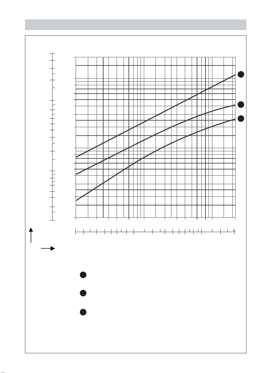
Capacity Chart
[lb/h]
50000
40000
30000
20000
10000
8000
6000
5000
4000
3000
2000
1000
Capacity [kg/h]
20000
10000
800
600
500
400
300
200
[kg/h]
8000
6000
5000
4000
3000
2000
1000
800
600
500
400
300
200
100
0.1 0.2 0.3 0.4 0.6 0.8 1 2 3 4 6 8 10 22 bar
3
2
1
Fig. 1
1.5 2 3 4 5 6 8 10 20 30 40 50 60 80 100 200 320 psi
Differential pressure (assuming discharge to atmospheric pressure)
Condensate discharge at boiling point
1
without banking-up
2
Condensate flowrate at 30 K below
saturation temperature
3
Max. discharge capacity of
cold condensate
3
Page 4
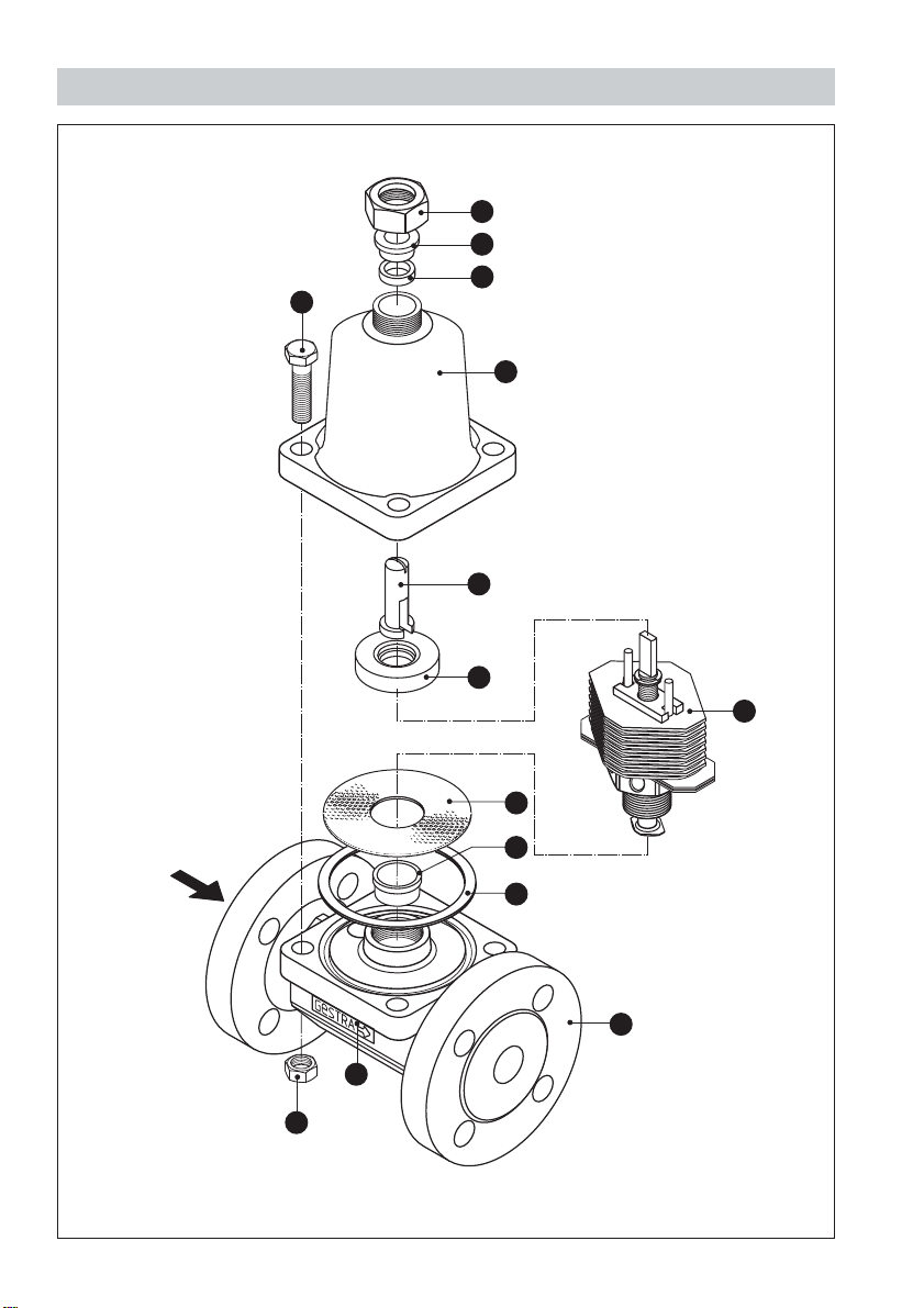
Parts Drawing
A
B
C
N
D
E
F
G
Fig. 2
4
H
I
J
K
L
M
Page 5

Key
A
Union nut ¾" BSP
B
Gland ring
C
Packing
Cover
D
Adjusting screw
E
Guide ring
F
G
Regulator
H
Strainer
Bush (force-fit, no spare part)
I
Cover gasket 92.7 x 102 x 1
J
Body
K
Name plate
L
Hexagon nut M 12
M
Hexagon bolt M 12
N
5
Page 6

Important Notes
Usage for the intended purpose
Use steam trap BK 15 only for the discharge of condensate in steam lines or for air
venting. Use this equipment only within the specified pressure and temperature
ratings and check corrosion resistance and chemical suitability for the application in
question.
Safety Note
The valve must only be installed by qualified staff.
Qualified staff are those persons who – through adequate training in engineering, the
use and application of safety equipment in accordance with regulations concerning
safety systems, and first aid & accident prevention – have achieved a recognised level
of competence appropriate to the installation and commissioning of this device.
Danger
The steam trap is under pressure during operation.
When loosening flanged connections, sealing plugs or the regulator hot
water or steam may escape. This presents the danger of severe burns and
scalds to the whole body.
Installation and maintenance work should only be carried out when the
system is depressurized: isolate the trap from both upstream and
downstream pressure.
The steam trap becomes hot during operation. This presents the risk of
severe burns to hands and arms. Installation and maintenance work should
only be carried out at room temperatures.
Sharp edges on internals present a danger of cuts to hands. Always wear
industrial gloves for installation and maintenance work.
Ratings pursuant to article 9 of the PED1)
Fluid
Use no yes no yes
Category I
Nominal size DN 40–50 mm 40 –50 mm
CE marking no yes
Type
1
) PED = Pressure Equipment Directive
gas liquid
1212
Exception pursuant
to article 3.3
BK 15
CL 150
BK 15
PN 40 CL 300
6
Page 7

Explanatory Notes
Scope of Supply
BK 15
1 Steam trap type BK 15
1 Installation manual
Description
Thermostatic/thermodynamic steam trap with corrosion-resistant regulator unaffected
by waterhammer. The Duo stainless steel regulator is externally adjustable. With
integral strainer and non-return valve action. Asbestos-free cover gasket (graphite).
Installation in any position.
The steam trap is adjusted at our factory to discharge condensate with virtually no
banking-up. More undercooling (banking-up of condensate) can be manually adjusted
during operation from the outside.
Function
During start-up of the plant the Duo stainless steel plates are flat. The service
pressure acts in the opening direction, the valve is completely open. As the
condensate temperature rises, the plates deflect, drawing the stage nozzle towards
the closed position. As the condensate temperature sinks, the deflection of the Duo
stainless steel plates decreases and the steam trap opens at the adjusted opening
temperature.
The thermostatic and spring characteristics of the stack of plates are balanced such
that condensate is always discharged at a given undercooling temperature.
The trap provides automatic air-venting at start-up and during operation. The correct
functioning of the BK 15 is neither affected by upstream pressure variations nor by
back pressure. The BK 15 can also be used for thermal air-venting in steam systems.
Technical Data
Pressure/Temperature Ratings PN 40
Body material Forged steel 1.0460 (P250GH / C22.8) / ASTM A105
Nominal sizes (DN) 40, 50
Connections Flanged to DIN PN 40
Service pressure PMA [barg] 40 35 28 21 14.5
[psig] 580 508 406 305 210
Related temperature TMA [°C] 20 200 300 400 450
[°F] 68 392 572 752 842
7
Page 8

Explanatory Notes – continued –
Technical Data – continued –
Pressure/Temperature Ratings Class 300
Body material Forged steel 1.0460 (P250GH / C22.8) / ASTM A105
Nominal sizes (DN) 40, 50
Connections Flanged to ASME Class 300
Service pressure PMA [barg] 51 43.9 38.9 34.6 20.2
Related temperature TMA [°C] 20 200 300 400 450
Pressure/Temperature Ratings Class 150
Body material Forged steel 1.0460 (P250GH / C22.8) / ASTM A105
Nominal sizes (DN) 40, 50
Connections Flanged to ASME Class 150
Service pressure PMA [barg] 19.7 14 10.2 6.5 4.6
Related temperature TMA [°C] 20 200 300 400 450
Admissible differential pressure1)2)
Differential pressure ∆PMX 22 barg (319 psig)
1
) Note pressure/temperature ratings 2) Inlet pressure minus outlet pressure
[psig] 740 637 565 500 293
[°F] 68 392 572 752 842
[psig] 287 203 149 94.3 66.7
[°F] 68 392 572 752 842
Materials EN DIN ASTM equivalent
Body P250GH (1.0460) C22.8 (1.0460) A105
Cover P250GH (1.0460) C22.8 (1.0460) A105
Bolts 42CrMo4 (1.7225) A193 B7
Body gasket graphite
Regulator stainless steel
Other internals stainless steel
Corrosion Resistance
When used for its intended purpose the safe functioning of the steam trap will not be
impaired by corrosion.
Sizing
The valve body must not be subjected to pulsating loads. The dimensional allowances
for corrosion reflect the latest state of technology.
8
Page 9

Explanatory Notes – continued –
Name Plate/Marking
Nominal size
Ratings acc. to
EN ISO 26552
For further specifications according to EN 19 see trap body.
Fig. 4
Installation
Regulator
Standard design
U
30 K undercooling
BK 15
The steam trap BK 15 can be installed in any position. In the case of a horizontal
installation, make sure that the cover is at the top.
Flanged Design
1. Take care of correct position of installation.
2. Take care of flow direction. The flow arrow is on the trap body.
3. Consider space required for opening trap. When the trap is installed a minimum
space of 90 mm is required for removing cover .
4. Remove plastic plugs. They are only used as transit protection.
5. Clean seating surfaces of both flanges.
6. Install steam trap.
D
9
Page 10

Installation – continued –
Screwed-Socket Design
1. Take care of correct position of installation.
2. Take care of flow direction. The flow arrow is on the trap body.
3. Consider space required for opening trap. When the trap is installed a minimum
space of 90 mm is required for removing the cover .
4. Remove plastic plugs. They are only used as transit protection.
5. Clean female threads of the screwed sockets.
6. Install steam trap.
Socket-Weld Design
1. Take care of correct position of installation.
2. Take care of flow direction. The flow arrow is on the trap body.
3. Consider space required for opening trap. When the trap is installed a minimum
space of 90 mm is required for removing the cover .
4. Remove plastic plugs. They are only used as transit protection.
5. Remove regulator as described under Maintenance.
6. Clean socket-weld ends.
7. Arc-weld trap only manually (welding process 111 and 141 in accordance with
DIN EN 24063).
Butt-Weld Design
D
D
1. Take care of correct position of installation.
2. Take care of flow direction. The flow arrow is on the trap body.
3. Consider space required for opening trap. When the trap is installed a minimum
space of 90 mm is required for removing the cover .
D
4. Remove plastic plugs. They are only used as transit protection.
5. Clean butt-weld ends.
6. Arc-weld trap only manually (welding process 111 and 141 in accordance with
DIN EN 24063) or use gas-welding process (welding process 3 in accordance with
DIN EN 24063).
Attention
■
Only qualified welders certified e. g. according to DIN EN 287 may weld
the steam trap into pressurized lines.
■
Do not insulate the steam trap.
Heat T reatment of Welds
A subsequent heat treatment of the welds is not required.
10
Page 11

Commissioning
BK 15
Make sure that all flange bolts are firmly fastened, ensuring tight shut-off.
Danger
The steam trap is under pressure at start-up and during operation.
When loosening the union nut hot water or steam may escape. This
A
presents the danger of severe burns and scalds to the whole body.
The steam trap becomes hot during operation. This presents the risk of
severe burns to hands and arms. Installation and maintenance work should
only be carried out at room temperatures.
Always wear industrial gloves when adjusting the regulator.
Adjust Regulator (Undercooling, Controlled Steam Flowrate)
The regulator of the BK 15 is adjusted at our factory to close steam-tight and open as
soon as condensate is formed. If a certain undercooling and, consequently, banking-up
of condensate is required for e. g. a heating process, the trap setting can be modified at
start-up and during operation:
1. Take notice of the danger note. Slacken union nut (one turn) and turn adjustment
E
screw clockwise with a screwdriver. 1/8 turn corresponds to approx. 4 K (degC)
A
change in discharge temperature. Starting from factory setting you can turn the
adjustment screw up to 1.5 turns to the right.
E
2. If required you can also adjust a controlled steam flowrate. Starting from factory
setting turn the adjustment screw for this purpose 1.5 turns to the left.
3. Tighten union nut with a max. torque of 30 Nm.
A
E
Restore Factory Setting
The regulator of the BK 15 is adjusted at our factory to close steam-tight and open as
soon as condensate is formed. If necessary, the factory setting can be restored as
follows:
1. To depressurize the steam trap cut off steam and – in the case of back pressure –
condensate line(s). Let the trap cool down to room temperature.
2. Undo union nut and turn adjustment screw with a screwdriver clockwise until a
A
E
resistance is felt.
3. Turn adjustment screw 3 turns anticlockwise. The steam trap will now discharge
E
condensate with virtually no banking-up (factory setting).
4. Tighten union nut with a max. torque of 30 Nm.
A
Tools
■
Screwdriver 5.5/100 mm to DIN 5265, form A
■
Spanner A.F. 36 mm to DIN 3113, form B
■
Torque spanner 20 – 160 Nm to DIN ISO 6789
11
Page 12

Operation
BK 15
The BK 15 requires maintenance for certain operating modes (see Maintenance).
The control unit of the BK 15 can be adjusted during operation (see Commissioning).
Maintenance
GESTRA steam traps type BK 15 do not require any special maintenance. However, if
used in new installations which have not been rinsed it may be necessary to check and
clean the trap.
Check Steam Trap
You can check the steam trap BK 15 for steam loss during operation using the
ultrasonic measuring unit VAPOPHONE
®
or the test unit TRAP
test
®
.
Should you detect any loss of live steam clean the trap and/or replace the regulator.
Clean/Replace Regulator
1. Take notice of the note “Danger” on page 6.
2. Undo hexagon bolts . Remove cover from the body .
3. Remove and clean regulator .
4. Replace regulator in case of visible signs of wear or damage.
N
G
G
D K
5. Clean body, internals and all gasket surfaces.
6. Apply heat-resistant lubricant to all threads and the seating surface of the nozzle
insert and the cover (use for instance WINIX
®
2150).
7. Screw in regulator and tighten with a torque of 140 Nm.
8. Insert new gasket .
9. Place cover onto the body. Tighten hexagon bolts alternately and in several steps
J
N
to a torque of 45 Nm.
Tools
■
Spanner A. F. 32 mm to DIN 3113, form B
■
Spanner A. F. 18 mm to DIN 3113, form B
■
Torque spanner 20 – 160 Nm to DIN ISO 6789
WINIX® 2150 is a registered trademark of WINIX GmbH, Norderstedt
12
Page 13

Maintenance – continued –
Clean/Replace Strainer
1. Take notice of note “Danger” on page 6.
2. Undo hexagon bolts . Remove cover from the body .
3. Remov e regulator .
4. Remov e and clean strainer .
5. Clean body, internals and all gasket surfaces.
6. Apply heat-resistant lubricant to all threads and the seating surface of the nozzle
insert and the cover (use for instance WINIX
7. Insert strainer .
8. Screw in regulator and tighten with a torque of 140 Nm.
9. Insert new gasket .
10. Place cover onto the body. Tighten hexagon bolts alternately and in several
steps to a torque of 45 Nm.
Tools
■
Spanner A. F. 18 mm to DIN 3113, form B
■
Torque spanner 20 – 160 Nm to DIN ISO 6789
Torques
Item Designation Torque [Nm]
G
N
A
All torques given in the table are based at a room temperature of 20°C. Threads without lubricant.
N D K
G
H
H
G
J
Regulator 140
Hexagon bolts 45
Union nuts 30
®
2150).
N
WINIX® 2150 is a registered trademark of WINIX GmbH, Norderstedt
13
Page 14

Spare Parts
Spare Parts List
Item
GCJC
H
J
*) Minimum purchasing quantity 20 pcs. For smaller quantities please contact your local dealer.
Gasket*) 92.7 x 102 x 1, graphite 375699 375699
Designation
Packing*) 9 x 14 x 7 376552 376552
Regulator 098847 098847
Strainer, complete 375698 375698
Stock code Stock code
DN 40 DN 50
14
Page 15

Annex
Declaration of Conformity
We hereby declare that the pressure equipment BK 15, DN 40 - 50 mm conforms to
the following European Directive:
■
EC Pressure Equipment Directive (PED) No. 97/23 of 29 May 1997
Steam traps are pressure equipment as defined in article 1, section 2.1.4 of the PED.
Applied conformity assessment procedure: Module A as described in Annex III.
This declaration is no longer valid if modifications are made to the equipment without
consultation with us.
Bremen, 28th September 2001
GESTRA GmbH
Head of the Design Dept.
Uwe Bledschun
Academically qualified engineer
Quality Assurance Representative
Lars Bohl
Academically qualified engineer
15
Page 16

GESTRA Gesellschaften · GESTRA Companies · Sociétés GESTRA · Sociedades Gestra · Società GESTRA
Vertretungen weltweit · Agencies all over the world · Représentations dans le monde entier · Representaciones en todo el mundo · Agenzie in tutto il mondo
España
GESTRA ESPAÑOLA S.A.
Luis Cabrera, 86-88
E-28002 Madrid
Tel. 003491/ 5152032
Fa x003491/413 6747 ; 515 203 6
E-mail: gestra@gestra.es
Polska
GESTRA POLONIA Spolka zo.o.
Ul. Schuberta 104, P.O. Box 71
PL-80-172 Gdansk
Tel. 0048 58/3061002 oder 3061010
Fax 004858/3061003 oder 306 3300
E-mail: gestra@gestra.pl
France Portugal
Flowserve Flow Control S.A.S.
10 Avenue du Centaure, BP 8263
F-95801 CERGY PONTOISE CEDEX
Tél. 0 0331 /34432660
Fax 00331/34432687
E-mail: gnation@flowserve.com
GESTRA PORTUGUESA VALVULAS
LDA.
Av. Dr. Antunes Guimarães, 1159
Porto 4100-082
Tel. 00351 22/6198770
Fax 0035122/6107575
E-mail: gestra@gestra.pt
Italia
Italgestra S.r.l.
Via Carducci 125
l-20099 Sesto San Giovanni (MI)
Tel. 00 3902 /241012.1
Fax 003902 /24 1012.460
E-mail: info@italgestra.it
®
GESTRA GmbH
Postfach 1054 60
D-28054 Bremen
Münchener Str. 77
D-28215 Bremen
Tel. +49 (0) 421 35 03-0
Fax+49 (0) 421 35 03-393
E-mail
gestra.gmbh@gestra.de
Internet www.gestra.de
A Unit of Flowserve Corporation
810682-01/702c · ©2001 GESTRA GmbH · Bremen · Printed in Germany
16
 Loading...