

Page 1

GESTRA
GESTRA Steam Systems
BA 46
BA 47
BAE 46
BAE 47
Installation Instructions 818609-00
Continuous Blowdown Valve
BA 46, BA 47, BAE 46, BAE 47
1
Page 2

2
Contents
Page
Important Notes
Usage for the intended purpose .............................................................................................................5
Safety notes ...........................................................................................................................................5
Danger ...................................................................................................................................................5
Attention .................................................................................................................................................6
PED (Pressure Equipment Directive) ........................................................................................................6
ATEX (Atmosphère Explosible) .................................................................................................................6
Explanatory Notes
Scope of supply ...................................................................................................................................... 6
System description .................................................................................................................................7
Function .................................................................................................................................................7
Design .................................................................................................................................................... 8
Technical Data
Pressure ratings .....................................................................................................................................8
Materials ................................................................................................................................................8
Pressure/Temperature ratings .................................................................................................................8
Dimensions of end connections ..............................................................................................................9
Overall lengths ........................................................................................................................................9
Corrosion resistance ............................................................................................................................... 9
Sizing .....................................................................................................................................................9
Name plate / marking ...........................................................................................................................10
Dimensions BA 46, BA 47 ..................................................................................................................... 11
Dimensions BAE 46, BAE 47 ................................................................................................................. 12
Capacity chart for DN 15 to 32, capacity ranges at a glance
Capacity chart for DN 15 to 32, capacity range up to 310 kg/h ..............................................................14
Capacity chart for DN 15 to 32, capacity range up to 1020 kg/h ............................................................15
Capacity chart for DN 15 to 32, capacity range up to 2120 kg/h ............................................................16
Capacity chart for DN 40 and 50, capacity ranges at a glance ...............................................................17
Capacity chart for DN 40 and 50, capacity range up to 1340 kg/h .........................................................18
Capacity chart for DN 40 and 50, capacity range up to 4500 kg/h .........................................................19
Capacity chart for DN 40 and 50, capacity range up to 6300 kg/h .........................................................20
..................................................................13
Design
BA 46, BA 47 ........................................................................................................................................ 21
BAE 46, BAE 47 ....................................................................................................................................22
Key ....................................................................................................................................................... 23
Page 3

Contents – continued –
Page
Installation
BA 46, BA 47, BAE 46, BAE 47 ..............................................................................................................24
Attention ...............................................................................................................................................24
Valve with flanged ends ........................................................................................................................ 24
Valve with socket-weld ends .................................................................................................................24
Valve with butt-weld ends ....................................................................................................................24
Attention ...............................................................................................................................................25
Heat treatment of welds........................................................................................................................25
Reposition control lever by 180 ° (if position of installation is unfavourable) .......................................... 25
Install sample valve ..............................................................................................................................25
Wiring
Danger ...............................................................................................................................................26
Continuous blowdown valves BAE 46, BAE 47 with actuator .................................................................26
Factory settings of BAE 46, BAE 47 .......................................................................................................26
Commissioning
Danger ...............................................................................................................................................26
BA 46, BA 47, BAE 46, BAE 47 ..............................................................................................................26
Attention ...............................................................................................................................................27
Continuous blowdown valves BA 46, BA 47 without actuator ................................................................27
Continuous blowdown valves BAE 46, BAE 47 with actuator .................................................................27
Operation
Danger ...............................................................................................................................................27
BA 46, BA 47, BAE 46, BAE 47 ..............................................................................................................27
Attention ...............................................................................................................................................27
Calculating the amount of boiler blowdown ...........................................................................................28
Emergency Operation
BAE 46, BAE 47 ....................................................................................................................................28
Maintenance
Changing packing and internals of BA 46, BA 47 ........................................................................... 28 - 29
Changing packing and internals of BAE 46, BAE 47 ....................................................................... 29 - 30
Torques ................................................................................................................................................30
Tools .....................................................................................................................................................30
Removing internals ............................................................................................................................... 31
3
Page 4

4
Contents – continued –
Page
Retrofitting
Danger ...............................................................................................................................................32
Mounting the actuator ........................................................................................................................... 32
Toques ..................................................................................................................................................32
Tools .....................................................................................................................................................32
Spare Parts
Spare parts list ....................................................................................................................................33
Retrofitting Parts
Retrofitting parts list ............................................................................................................................34
Decommissioning
Danger .................................................................................................................................................34
Disposal................................................................................................................................................34
Annex
Declaration of Conformity ....................................................................................................................35
Page 5

Important Notes
Usage for the intended purpose
BA 46, BA 47:
Use the continuous blowdown valves BA 46, BA 47 only for discharging water from steam boilers to
ensure the correct water conditions in the boiler. Application in pipes within the admissible pressure/
temperature ratings, taking the chemical and corrosive effects on the pressure equipment into account.
BAE 46, BAE 47:
Use the continuous blowdown valves BAE 46, BAE 47 only in conjunction with the control equipment
KS 90, LRR 1-40 or LRR 1-5, LRR 1-6 for discharging water from steam boilers to ensure the correct
water conditions in the boiler. Application in pipes within the admissible pressure/temperature ratings,
taking the chemical and corrosive effects on the pressure equipment into account.
To ensure the safe operation of the BAE 46, BAE 47 mount only actuators that are explicitly specified by
GESTRA onto the control valve. Specified and approved actuators are:
ARIS EF 0.5, ARIS EF 1, ARIS EF 1-1 and ARIS EF 1-40.
Safety note
The equipment must only be installed and commissioned by qualified and competent staff.
Retrofitting and maintenance work must only be performed by qualified staff who – through adequate
training – have achieved a recognised level of competence.
Danger
The valve is under pressure during operation.
When loosening flanged connections, sealing plugs or stuffing boxes, hot water and
steam may escape.
The valve becomes hot during operation.
This presents the risk of severe burns to hands and arms.
Before servicing the valve or loosening flanges, stuffing box connections or sealing plugs
make sure that all connected lines are depressurised (0 bar) and cooled down to room
temperature (20 °C).
During operation moving internals can pinch one‘s hands or fingers. Do not touch
moving parts! The continuous blowdown valves BAE 46, BAE 47 are remote controlled
and can open and close very abruptly.
The terminal strips of the actuator EF ... are live during operation.
This presents the danger of electric shock.
Cut off power supply before fixing or removing the equipment.
Sharp edges on internals present a danger of cuts to hands. Always wear industrial
gloves when replacing the packing, valve seat or valve plug.
5
Page 6

6
Important Notes – continued –
Attention
The name plate specifies the technical features of the equipment. Note that any piece of
equipment without its specific name plate must neither be commissioned nor operated.
PED (Pressure Equipment Directive)
The equipment meets the requirements of the Pressure Equipment Directive 97/23/EC.
Application in fluids of group 2. With CE marking, except equipment according to section 3.3.
ATEX ( Atmosphère Explosible)
The valves BA 46, BA 47 can be used in potentially explosive areas, provided that the following notes
are observed:
The operating fluid must not generate excessively high temperatures. Electrostatic charges that may
be generated during operation must be discharged. Make sure that the stuffing box is tight and that
the valve spindle can run smoothly. The equipment can be used in Ex zones 1, 2, 21, 22 (1999/92/EC)
II 2 G/D c X.
According to the European Directive 94/9/EC the valves BAE 46, BAE 47 must not be used in
potentially explosive areas. For more information refer to our ATEX Declaration of Conformity.
Explanatory Notes
Scope of supply
BA 46
1 Continuous blowdown valve BA 46
1 Sample valve (not mounted)
1 Gasket A17 x 23 x 1.5
1 Installation manual
BA 47
1 Continuous blowdown valve BA 47
1 Sample valve (not mounted)
1 Gasket A17 x 23 x 1.5
1 Installation manual
Retrofitting kit for BA 46, BA 47
1 Electric actuator
EF 0.5, EF 1, EF 1-1 or EF 1-40
1 Mounting kit for coupling / mounting bracket
1 Installation manual for ARIS actuator EF...
Spare parts
1 Kit according to spare parts list, page 33
BAE 46
1 Continuous blowdown valve BAE 46
1 Sample valve (not mounted)
1 Gasket A17 x 23 x 1.5
1 Installation manual
1 Installation manual of the ARIS actuator EF...
1 Declaration of manufacturer
BAE 47
1 Continuous blowdown valve BAE 47
1 Sample valve (not mounted)
1 Gasket A17 x 23 x 1.5
1 Installation manual
1 Installation manual for ARIS actuator EF...
1 Declaration of manufacturer
Page 7

Explanatory Notes – continued –
System description
Due to the continuous evaporation process in the steam boiler the density and hence the TDS
(= Total Dissolved Solids) concentration of the boiler water is increased. The TDS level must remain
within the limits specified by the boiler manufacturer and applicable guidelines. For this purpose a
certain amount of boiler water (= boiler blowdown) is discharged continuously or periodically. The
continuous blowdown valves BA... and BAE... feature specially designed and wear resistant nozzle stems
that enter concentrically into a system of expansion chambers which are arranged one after the other,
making the valve well suited for the continuous discharge of boiler blowdown at very high differential
pressures. The continuous blowdown valves BA... and BAE ... are suitable for operation in steam boiler
plants according to TRD 604, EN 12952 and EN 12953
n BA 46 PN 40, manually operated
n BA 47 PN 63, manually operated
n BAE 46 PN 40, operated by the electric actuator EF...*)
n BAE 47 PN 63, operated by the electric actuator EF...*)
*) Explosion-proof actuators or actuators powered by d. c. or three-phase current are available
on request.
Function
The continuous blowdown valve BA 46/BA 47 is moved to its control position by means of the control
lever. Use the scale on the control lever to adjust the required amount of boiler blowdown.The required
amount of boiler blowdown is calculated with the aid of a formula or read off on a nomogram. The
continuous blowdown valve BAE 46/BAE 47 is motored to its control position by means of the actuator EF... The actuator is activated by the GESTRA conductivity controller KS 90 working in conjunction
with the GESTRA conductivity electrode LRGT 1...-1 or the conductivity controller LRR 1-5, LRR 1-6 in
combination with the GESTRA conductivity electrode LRG 16... or the conductivity controller LRR 1-40 in
conjunction with the conductivity electrode LRG 1..-40.
The actuator opens or closes the continuous blowdown valve as a function of the required amount of
boiler blowdown and the desired operating position, at which – independent of the actual electrical
conductivity of the boiler water – a freely selectable fundamental amount can be discharged by the BAE
46/BAE 47. The valve positions “OPEN” and “CLOSED” are limited by the cam-operated switch located in
the actuator, the “OPERATING POSITION” is variably adjustable by means of an operating cam. The power
flow towards the closing direction is transmitted via a rigid coupling with integrated torsion spring. The
coupling permits the actuator to travel a little bit further when the nozzle stem is pressed into the valve
seat.
The conductivity of the boiler water is monitored by the equipment combination consisting of a
conductivity electrode and a conductivity controller. The continuous evaporation process in the steam
boiler increases the boiler water density and, consequently, the TDS level, causing the conductivity of
the boiler water to rise. Once the set limit value is reached, the actuator receives an opening pulse from
the conductivity controller according to the deviation from the conductivity setpoint. When the adjusted
conductivity setpoint is attained, the actuator closes the continuous blowdown valve or returns to the
adjusted operating position. The valve positions “CLOSED” and “OPEN” are limited by the cam-operated
switch in the actuator, the “OPERATING POSITION” is variably adjustable by means of an operating cam
or a feedback potentiometer.
.
7
Page 8
8
Explanatory Notes – continued –
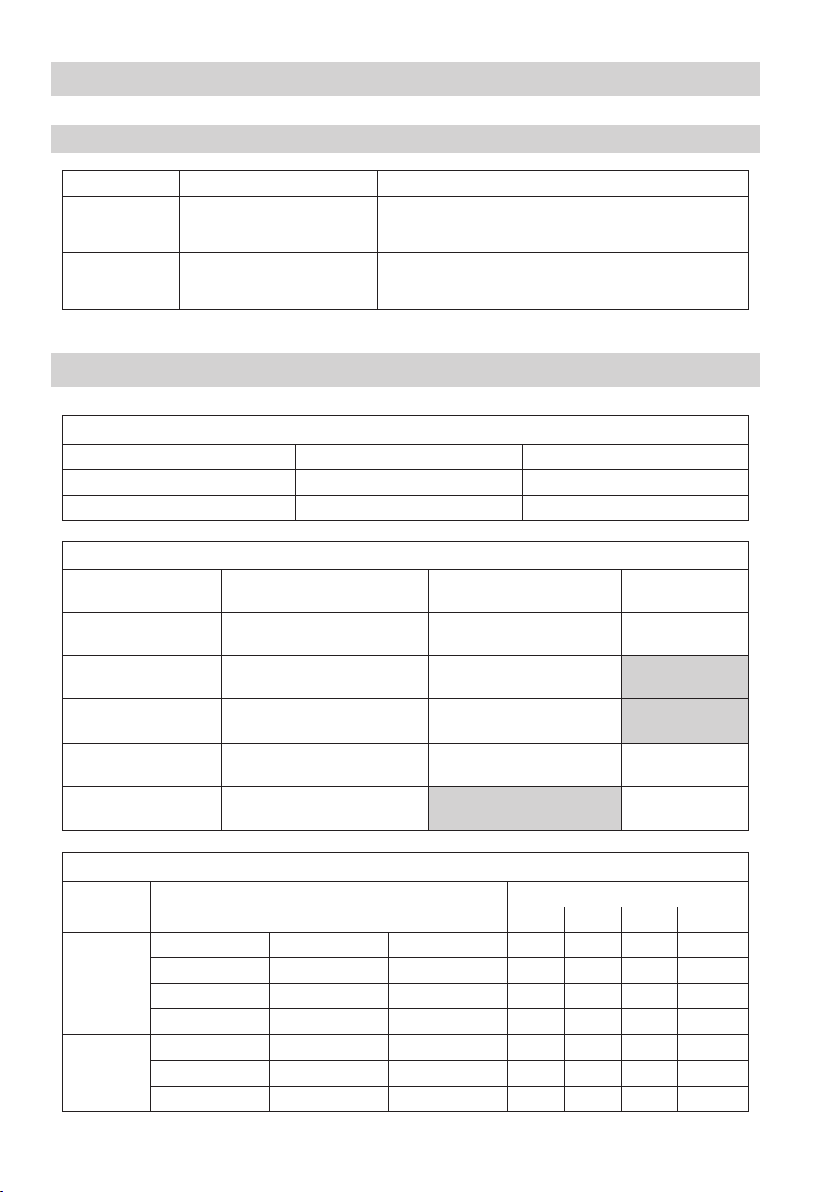
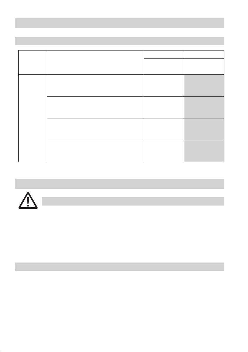
Design
Type Standard Special version
BA(E) 46
BA(E) 47
Flanged to
EN 1092-1, PN 40
Flanged to
EN 1092-1, PN 63
Flanged to ASME, Class 150, 300
Butt-weld ends for pipes to DIN or ASME
Socket-weld ends for pipes to DIN or ASME
Flanged to ASME, Class 400
Butt-weld ends for pipes to DIN or ASME
Socket-weld ends for pipes to DIN or ASME
Technical Data
Pressure ratings
Type EN ASME
BA(E) 46 PN 40 Class 150, 300
BA(E) 47 PN 63 Class 400
Materials
Designation EN DIN ASTM
Valve body
BA..., BAE...
Nozzle stem X20Cr13 (1.4021) X20Cr13 (1.4021)
Seat and stage sleeves X14CrMoS17 (1.4104) X14CrMoS17 (1.4104)
Locking screw A2-70 A2-70 A193 CL 2B-B8
Sealing plug 42CrMo4 (1.7225) A193 B7
P250GH (1.0460) C 22.8 (1.0460) A 105
Pressure/Temperature ratings
Type Ratings according to
EN 1092-1 1.0460*)
BA(E) 46
BA(E) 47
*) Material according to AD 2000
EN 1092-1 A105
ASME B16-34 A105 Class 150 17.7 13.8 10.2 198 / 14
ASME B16-34 A105
EN 1092-1 1.0460*)
EN 1092-1 A105
ASME B16-34 A105
PN 40 37.3 30.2 25.8 234 / 29
PN 40 40 37.9 33.5 246 / 36
Class 300 46.6 43.8 39.8 254 / 42
PN 63 58.8 47.6 40.6 257 / 44
PN 63 63 59.6 52.7 271 / 55
Class 400 62.1 58.4 53.1 270 / 55
max. pressure [bar] at
100 °C 200 °C 300 °C ts / p
max
Page 9

Technical Data – continued –
Dimensions of end connections
Outside diameter of pipe x wall thickness
Butt-weld ends for pipe*) [DN] 15 20 25 32 40 50
EN PN 40 21.3 x 2 26.9 x 2.3 33.7 x 3.4 42.4 x 2.6 48.3 x 2.6 60.3 x 2.9
EN PN 63 21.3 x 2 26.9 x 2.6 33.7 x 2.6 42.4 x 2.9 48.3 x 2.9 60.3 x 2.9
ASME Schedule 40 CL150/300 21.3 x 2.8 26.7 x 2.9
ASME Schedule 80 CL400/300 21.3 x 3.7 26.7 x 3.9 33.4 x 4.5 42.2 x 4.8 48.3 x 5.1 60.3 x 5.5
Inside diameter x depth
Socket-weld ends EN/ASME**) [DN] 15 20 25 32 40 50
EN/ASME 21.8 x 10 27.3 x 13 34.1 x 13 42.8 x 13 48.8 x 13 61.3 x 16
*) The dimensions (outside diameter of pipe x wall thickness) refer to the connecting pipe, not to the dimensions
of the butt-weld end!
**) The dimensions (inside diamter x depth) refer to the socket-weld ends.
Overall lengths
End connection [mm]
[inch]
Flange Class 150 L 150 150 160 180 230 230
Flange Class 300 L 150 150 160 180 230 230
Flange Class 400 L 216 216 250
Butt-weld ends L 200 200 200 200 250 250
Socket-weld ends L 200 200 200 200 250 250
Flange PN 40 L 150 150 160 180 200 230
Flange PN 63 L 190 220 250
Weight BA 4... [kg] 4.7 5.3 5.8 7.1 10.7 12.5
Weight BAE 4... [kg] 8.8 9.4 9.9 11.2 14.8 16.6
15
½
33.4 x 3.4 42.2 x 3.6 48.3 x 3.7 60.3 x 3.9
20
¾
25
1
32
1¼
40
1½
50
2
Corrosion resistance
When used for its intended purpose, the safe functioning of the equipment will not be impaired by
corrosion.
Sizing
The valve body must not be subjected to sharp increases in pressure. The sizing and dimensional
allowances for corrosion reflect the latest state of technology.
9
Page 10

10
Technical Data – continued –
MADE BY GESTRA AG
BA 47
0525
TMA 300°C
PN 63
DN
MADE BY GESTRA AG
BA 46
0525
TMA 572°F
B16.34 CL300
DN
MADE BY GESTRA AG
BA 47
0525
TMA 572°F
B16.34 CL400
DN
MADE BY GESTRA AG
BA 46
TMA 300°C
DN 25 PN 40
Name plate / marking
For pressure and temperature ratings see the designation on the valve body or the data given on the
name plate. Further details are given in various GESTRA publications, such as datasheets and technical
information.
In accordance with EN 19, the following type and design data are indicated on the name plate or body:
n Manufacturer
n Type designation
n Pressure class PN or Class
n Material number
n Maximum temperature
n Maximum pressure
n Direction of flow
n Stamp on valve body, e. g. specificies the manufacturing quarter and year
(in this case the 4
th
Nominal size
4
05
quarter of 2005)
max. admissible temperature
Nominal pressure
Letter “E”
Fig. 1
Page 11
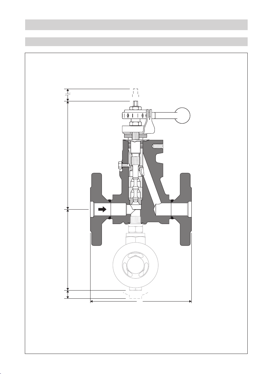
Technical Data – continued –
Dimensions BA 46, BA 47
180
DN 15-32: 172
DN 40, 50: 213DN 40, 50: 132
Fig. 2
DN 15-32: 126
20
L
11
Page 12

12
Technical Data – continued –
Dimensions BAE 46, BAE 47
100
DN 15-32: 388
DN 40, 50: 428DN 40, 50: 132
Fig. 3
DN 15-32: 126
20
L
Page 13
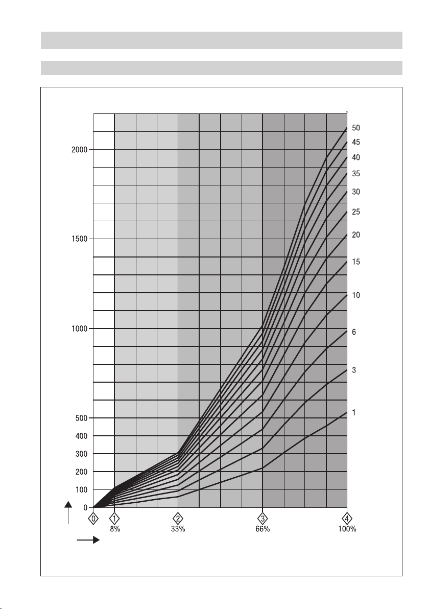
Technical Data – continued –
Capacity chart for DN 15 to 32, capacity ranges at a glance
Boiler pressure [bar]
Fig. 4
Hot water capacity [kg/h]
Position of control lever
13
Page 14

14
Technical Data – continued –
Capacity chart for DN 15 to 32, capacity range up to 310 kg/h
Boiler pressure [bar]
Fig. 5
Hot water capacity [kg/h]
Position of control lever
Page 15

Technical Data – continued –
Capacity chart for DN 15 to 32, capacity range up to 1020 kg/h
Boiler pressure [bar]
Fig. 6
Hot water capacity [kg/h]
Position of control lever
15
Page 16

16
Technical Data – continued –
Capacity chart for DN 15 to 32, capacity range up to 2120 kg/h
Boiler pressure [bar]
Fig. 7
Hot water capacity [kg/h]
Position of control lever
Page 17

Technical Data – continued –
Capacity chart for DN 40 and 50, capacity ranges at a glance
Boiler pressure [bar]
Fig. 8
Hot water capacity [kg/h]
Position of control lever
17
Page 18

18
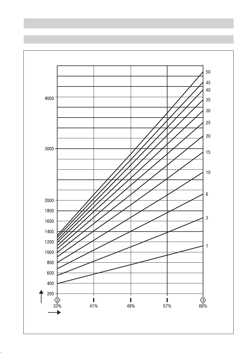
Technical Data – continued –
Capacity chart for DN 40 and 50, capacity range up to 1340 kg/h
Boiler pressure [bar]
Fig. 9
Hot water capacity [kg/h]
Position of control lever
Page 19
Technical Data – continued –
Capacity chart for DN 40 and 50, capacity range up to 4500 kg/h
Boiler pressure [bar]
Fig. 10
Hot water capacity [kg/h]
Position of control lever
19
Page 20
20
Technical Data – continued –
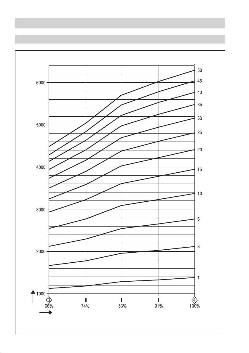
Capacity chart for DN 40 and 50, capacity range up to 6300 kg/h
Boiler pressure [bar]
Fig. 11
Hot water capacity [kg/h]
Position of control lever
Page 21

Design
BA 46, BA 47
U
T
S
R
A
B
C
D
E
F
G
H
I
I
J
K
Q
P
Fig. 12
L
M
N
O
21
Page 22

22
Design – continued –
BAE 46, BAE 47
1
2
3
4
5
Fig. 13
K
8
6
Open Close
7
Page 23

Key
A Stuffing box screw
B Scale plate
C Stuffing box gland
D Disk spring (3 pieces)
E Spring sleeve
Packing with 4 wiper rings
F
G Guide sleeve
H Wearing bushing
I Stage bushing
J Seat bushing
K Valve body
L Nameplate
M ATEX marking
N Gasket A17 x 23 x 1.5
O Sealing plug (connection for a sample valve)
P Locking screw
Q Gasket C6 x 10 x 1.5 (DN 15-32) C10 x 16 x1.5 (DN 40, 50)
R Nozzle stem
S Scale
T Hexagon nut
U Control lever
1 Actuator
2 Compression spring
3 Thrust washer
4 Grooved dowel pin ISO 8742
5 Mounting bracket
6 Checking pin
7 Hexagon screw with washer
8 Coupling
23
Page 24

24
Installation
BA 46, BA 47, BAE 46, BAE 47
Mount the continuous blowdown valve, taking the direction of the flow arrow into account. The
blowdown take-off point must be located in the steam boiler underneath the low level mark and close
to the steam outlet. The continuous blowdown valve can be installed in horizontal and vertical
pipes. The continuous blowdown valve is delivered ready for installation, with the actuator mounted
or supplied separately. Before commissioning read the technical documentation provided by the
manufacturer of the actuator and store the document together with the installation manual “BA 46, BA
47, BAE 46, BAE 47” in a sheltered place. The continuous blowdown valve is delivered with a sample
valve (not installed). This sample valve must only be attached to the continuous blowdown valve at the
intended point. Before commissioning read the technical documentation provided by the manufacturer
of the sample valve and store the document together with the installation manual “BA 46, BA 47, BAE
46, BAE 47” in a sheltered place.
Attention
n Note that the inclination of the actuator when installed must not exceed 90
Valve with flanged ends
1. Ensure correct position of installation. The control lever
2. Observe direction of flow. The flow arrow is on the valve body.
3. Consider space required for servicing the valve. When the continuous blowdown valve is installed a
minimum space of at least 180 mm is required for removing the equipment or for the subsequent
installation of the actuator.
4. Remove plastic plugs. They are only used as transit protection.
Clean seating surfaces of both flanges.
5.
6. Install the continuous blowdown valve.
Valve with socket-weld ends
1. Ensure correct position of installation. The control lever
2. Observe direction of flow. The flow arrow is on the valve body
Consider space required for servicing the valve. When the continuous blowdown valve is installed a
3.
minimum space of at least 180 mm is required for removing the equipment or for the subsequent
installation of the actuator.
Remove plastic plugs. They are only used as transit protection.
4.
5. Clean socket-weld ends
6. Arc-weld trap only manually (welding process 111 and 141 to ISO 4063) or apply gas-welding
process (welding process 3 in accordance with ISO 4063).
Valve with butt-weld ends
1. Ensure correct position of installation. The control lever
2. Observe direction of flow. The flow arrow is on the valve body.
3. Consider space required for servicing the valve. When the continuous blowdown valve is installed
a minimum space of at least 180 mm is required for removing the equipment or for the subsequent
installation of the actuator.
4. Remove plastic plugs. They are only used as transit protection.
5. Clean butt-weld ends.
6. Arc-weld trap only manually (welding process 111 and 141 to ISO 4063) or apply gas-welding
process (welding process 3 in accordance with ISO 4063)
U must be freely movable.
U must be freely movable.
.
U must be freely movable.
°!
Page 25

Installation – continued –
Attention
n Only qualified welders certified according to EN 287-1 may weld continuous
blowdown valves in pressurised lines.
Heat treatment of welds
After welding the continuous blowdown valve in place the welds might require a subsequent heat
treatment (stress-relief annealing process to DIN EN 100529). Note that the heat treatment must be
limited to the area close to the welds. The internal parts of the continuous blowdown valve do not have
to be removed before performing the heat treatment.
Reposition control lever by 180 ° (if position of installation is unfavourable)
If the position of installation is unfavourable (flow from right to left), it may be necessary to reposition the
control lever by 180
1. Take heed of the danger note on page 5.
2. Unscrew the hexagon nut
3. Undo stuffing box screws
by 180
4. Screw out nozzle stem
7 Nm (DN 15 – 32) or 11 Nm (DN 40, 50).
5. Turn nozzle stem
and align scale S with the scale plate B such that the diamond-shaped marker “0” is in the
middle of the scale plate.
6. Screw hexagon nut
20 Nm while holding the control lever.
° so that the scale plate can be seen.
T and detach control lever U with the aid of a pulling device.
A, remove stuffing box gland C and scale plate B. Turn scale plate
° and put it back in place.
R by half a turn and tighten stuffing box screws A with a torque of
R into the closed position, applying a torque of 7 Nm. Put control lever U in place
T onto the threaded part of the nozzle stem R and tighten with a torque of
Install sample valve
1. Unscrew sealing plug
2. Observe installation instructions of the sample valve.
3. Install the sample valve, applying rules of good practice.
O and remove gasket N.
25
Page 26

26
Wiring
Danger
During operation moving internals can pinch one‘s hands or fingers. Do not touch moving
parts! The continuous blowdown valves BAE 46, BAE 47 are remote controlled and can
open and close very abruptly.
The terminal strips of the actuator EF ... are live during operation.
This presents the danger of electric shock.
Cut off power supply before fixing or removing the equipment.
Continuous blowdown valves BAE 46, BAE 47 with actuator
Apart from the positions OPEN and CLOSED you can select an OPERATING POSITION for the actuators
EF 0.5 and EF 1. The OPERATING POSITION allows the continuous discharge of a definded amount
of boiler water. The OPERATING POSITION can be adjusted in the actuator via the switching cam. For
more information refer to the attached installation manual “Actuators EF...”. The actuator EF 1-1 has a
feedback potentiometer ( 0 – 1000 ohm) but no switching cam for setting an OPERATING POSITION. For
more information on the setting refer to the attached installation manual “Actuators EF...”. The actuator
EF 1-40 sends at regular intervals a data telegram to the controller LRR 1-40. The data are transferred
via CAN bus in accordance with DIN ISO 11898, using the CANopen protocol. For more information refer
to the installation manual of the actuator EF 1-40.
Wire the actuator EF... in accordance with the attached installation manual “Actuators EF...”.
Factory settings of BAE 46, BAE 47
The default settings of the actuators EF 0.5 and EF 1 are: CLOSED (scale position “0”), OPERATING
POSITION (scale position “1”) and OPEN (scale position “4”),
In the OPERATING POSITION a predefined amount of boiler water is continuously discharged. The
OPERATING POSITION can be set in the actuator via the switching cam. For more information on the
adjustment refer to the installation manual “Actuators EF...”. The default settings of the actuators EF 1-1
and EF 1-40 are: CLOSED (scale position “0”) and OPEN (scale position “4”).
Fig. 4, Fig. 5
Commissioning
Danger
The control lever of the continuous blowdown valve and the coupling of the actuator
become hot during operation. This presents the risk of severe burns to hands and arms
when touching the control lever or the coupling. Do not operate the equipment unless you
are wearing thermally insulated and temperature resistant safety gloves.
BA 46, BA 47, BAE 46, BAE 47
Make sure that the flanged connections of the BA 46, BA 47, BAE 46, BAE 47 are securely tightened and
not leaking. Retighten the stuffing box C if there is a leak in this area.
Page 27

Commissioning – continued –
Attention
n As the stuffing box screws are tightened the break-out force and the frictional forces
of the nozzle steam are increased.
n The break-out force and the frictional forces of the nozzle steam must not exceed the
max. allowable operating forces of the actuator.
n Excessive fastening of the stuffing box screws impairs the correct functioning of the
continuous blowdown valve and can cause jamming of the nozzle stem.
n If the nozzle stem is jammed, the continuous blowdown valve can no longer open,
control or close.
Continuous blowdown valves BA 46, BA 47 without actuator
The amount of boiler blowdown dictated by the operating conditions can be adjusted by means of the
control lever on the continuous blowdown valve. For more information please refer to the capacity charts
on pages 13 to 20.
Continuous blowdown valves BAE 46, BAE 47 with actuator
Use the control equipment KS 90, LRR 1-40, LRR 1-5 or LRR 1-6 to set the required TDS level of the
boiler water. Please compare the resulting valve positions (see scale on the control lever) with the values
indicated in the capacity charts on page 13 to 20.
Operation
Danger
The control lever of the continuous blowdown valve and the coupling of the actuator
become hot during operation. This presents the risk of severe burns to hands and arms
when touching the control lever or the coupling. Do not operate the equipment unless you
are wearing thermally insulated and temperature resistant safety gloves.
BA 46, BA 47, BAE 46, BAE 47
Make sure that the flanged connections of the BA 46, BA 47, BAE 46, BAE 47 are securely tightened and
not leaking. Retighten the stuffing box C if there is a leak in this area.
Attention
n As the stuffing box screws are tightened the break-out force and the frictional forces
of the nozzle steam are increased.
n The break-out force and the frictional forces of the nozzle steam must not exceed the
max. allowable operating forces of the actuator.
n Excessive fastening of the stuffing box screws impairs the correct functioning of the
continuous blowdown valve and can cause jamming of the nozzle stem.
n If the nozzle stem is jammed, the continuous blowdown valve can no longer open,
control or close.
27
Page 28

28
Operation – continued –
Calculating the amount of boiler blowdown
Amount of boiler water to be discharged
Q · S
A =
K – S
A = Amount of boiler
blowdown [kg/h]
Q = Boiler capacity [kg/h]
S = Conductivity of feedwater
[
µs/cm]
K = Admissible conductivity of
boiler water [
µs/cm]
Example
Boiler pressure: 15 bar
Nominal size of the continuous blowdown valve: DN 20
Boiler capacity: Q = 10000 kg/h
Conductivity of feedwater: S = 100 µs/cm
Admissible conductivity of the boiler water: K = 3000 µs/cm
Amount of boiler water to be discharged: A ≈ 345 kg/h
10 % of which is intermittently blown out:
Amount of continuous blowdown: A1 ≈ 310 kg/h
Set control lever according to scale to an opening of 41 %,
≈ 35 kg/h
Fig. 6
Emergency Operation
BAE 46, BAE 47
Cut off power supply to the actuator and lift the coupling 8 approx. 1 cm by hand. Fig. 13
1.
Use the scale S on the control lever U to set the desired blowdown rate, Fig. 13
2.
Maintenance
The continuous blowdown valves BA 46, BA 47, BAE 46, BAE 47 do not require any special maintenance.
Depending on the quality of the boiler water it might be necessary to service the valve every one or two
years.
Changing packing and internals of BA 46, BA 47
1 Take heed of the danger note on page 5.
2. Unscrew the hexagon nut
3. Undo stuffing box screws
and spring sleeve
4. Unscrew nozzle stem
5. Unscrew locking screw
6. Unscrew sealing plug
7. Use a brass drift punch d = 14.8 mm to force out the internals
8. Clean and, if required, exchange valve body
9. Apply glue “Loctite
10. Align wearing bushing
screw
11. Screw in the locking screw
5 Nm (DN 15 – 32) or 11 Nm (DN 40, 50) when cold.
12. Align and insert the guide sleeve
on the locking screw
13. Insert new wiper rings and packing rings
14. Apply lubricant (type WINIX
P.
T and detach control lever U with the aid of a pulling device.
A, remove stuffing box gland C, scale plate B, disk springs D
E.
R and pull is out of the valve body.
P and remove gasket Q.
O and remove gasket N.
K and internals.
® 620” to seat bushing J and put it in place. Insert stage bushing I.
H in such a way that the groove is on the longitudinal axis of the locking
P together with gasket Q and tighten it with a torque of
G in such a way that the groove on the longitudinal axis is
P, Fig. 12.
F as shown, Fig. 12.
® 2010) to the thread and sealing surface of the nozzle stem.
F to J, Fig. 14
Page 29

Maintenance – continued –
Changing packing and internals of BA 46, BA 47 – continued –
15. Insert nozzle stem R and screw it into the guide sleeve G by two turns.
16. Insert spring sleeve
17. Put scale plate
18. Screw out nozzle stem
7 Nm (DN 15 – 32) or 11 Nm (DN 40, 50).
19. Turn nozzle stem
place and align scale
middle of the scale plate.
20. Screw hexagon nut
20 Nm while holding the control lever.
21. Screw sealing plug
130 Nm or screw in the sample valve with the gasket according to the instructions given by the
manufacturer.
Changing packing and internals of BAE 46, BAE 47
1. Take heed of the danger note on page 5.
2. Cut off power supply to actuator
3. Undo hexagon screws
4. Unscrew the hexagon nut
5. Undo stuffing box screws
spring sleeve
6. Unscrew nozzle stem
7. Unscrew locking screw
8. Unscrew sealing plug
9. Use a brass drift punch d = 14.8 mm to force out the internals
10. Clean and, if required, exchange valve body
11. Apply glue type “Loctite
12. Align wearing bushing
screw
13. Screw in the locking screw
5 Nm (DN 15 – 32) or 11 Nm (DN 40, 50) when cold.
14. Align and insert the guide sleeve
is on the locking screw
15. Insert new wiper rings and packing rings
16. Apply lubricant (type WINIX
17. Insert nozzle stem
18. Insert spring sleeve
19. Put scale plate
20. Screw out nozzle stem
7 Nm (DN 15 – 32) or 11 Nm (DN 40, 50).
21. Turn nozzle stem
P.
place and align scale S with the scale plate B such that the diamond-shaped marker “0” is in the
middle of the scale plate.
E and disk springs D in the shown sequence.
B and stuffing box gland C in place and tighten stuffing box screws A slightly.
R by half a turn and fasten stuffing box screws A with a torque of
R into the closed position, applying a torque of 7 Nm. Put control lever U in
S with the scale plate B such that the diamond-shaped marker “0” is in the
T onto the threaded part of the nozzle stem R and tighten with a torque of
O together with gasket N into the valve body and tighten with a torque of
1.
7 and remove actuator and coupling 8.
T and detach control lever U with the aid of a pulling device.
A, remove stuffing box gland C, scale plate B, disk springs D and
E.
R and pull is out of the valve body.
P and remove gasket Q.
O and remove gasket N.
F to J, Fig. 14
K and internals.
® 620” to seat bushing J and put it in place. Insert stage bushing I.
H in such a way that the groove is on the longitudinal axis of the locking
P together with gasket Q and tighten it with a torque of
G in such a way that the groove on the longitudinal axis
P, Fig. 12.
F as shown, Fig. 12.
® 2010) to the thread and sealing surface of the nozzle stem.
R and screw it into the guide sleeve G by two turns.
E and disk springs D in the shown sequence.
B and stuffing box gland C in place and tighten stuffing box screws A slightly.
R by half a turn and fasten stuffing box screws A with a torque of
R into the closed position, applying a torque of 7 Nm. Put control lever U in
WINIX® 2010 is a registered trademark of WINIX GmbH, Norderstedt
LOCTITE® is a registered trademark of HENKEL KgaA, Düsseldorf
29
Page 30

30
Maintenance – continued –
Changing packing and internals of BAE 46, BAE 47 – continued –
22. Screw hexagon nut T onto the threaded part of the nozzle stem R and tighten with a torque
of 20 Nm while holding the control lever.
Screw sealing plug O together with gasket N into the valve body and tighten with a torque of
23.
130 Nm or screw in the sample valve with the gasket according to the instructions given by the
manufacturer.
Put coupling 8 onto control lever U and fix the mounting bracket 5 and actuator 1 to the valve
24.
body using the hexagon screws 7. Adjust control lever until the coupling makes contact.
Align the actuator, making sure that the coupling 8 is level on the control lever. Fasten hexagon
25.
screws 7 with a torque of 7 Nm.
Adjust the switching cams for OPEN, CLOSED and OPERATING POSITION or, if fitted, the feedback
26.
potentiometer according to the attached installation manual “Actuators EF...”.
Set the switching cam for CLOSED in the actuator such that the torque checking pin 6 is to the
27.
right but does not touch the checking hole.The closing torque in this position is 10 Nm. Fig. 13
Torques
Torque required
Item
A
O
P
R
T
7
All torques indicated in the table are based on a room temperature of 20 °C.
Continuous blowdown valve
BA 46, BA 47, BAE 46, BAE 47 7 11
BA 46, BA 47, BAE 46, BAE 47 130
BA 46, BA 47, BAE 46, BAE 47 5 11
BA 46, BA 47, BAE 46, BAE 47 7
BA 46, BA 47, BAE 46, BAE 47 20
BAE 46, BAE 47 7
for tightening [Nm]
DN 15-32 DN 40,50
Tools
n Combination spanner 7 mm A. F., DIN 3113, form B
n Combination spanner 10 mm A. F., DIN 3113, form B
n Combination spanner 13 mm A. F., DIN 3113, form B
n Combination spanner 16 mm A. F., DIN 3113, form B
n Combination spanner 17 mm A. F., DIN 3113, form B
n Torque spanner 1 – 12 Nm, ISO 6789
n Torque spanner 8 – 40 Nm, ISO 6789
n Torque spanner 80 – 400 Nm, ISO 6789
n Punch 14.8 x 220 CuZn (brass)
n Hammer 300 g, Din 1041
n Self-centering pulling device, size 0
Page 31
Maintenance – continued –
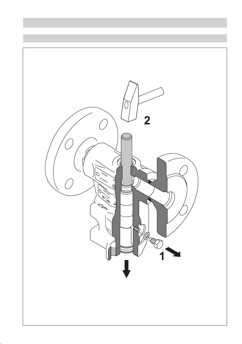
Removing internals
Fig. 14
31
Page 32

32
Retrofitting
GESTRA continuous blowdown valves BA 46 and BA 47 can be retrofitted with a GESTRA actuator EF...
(BAE 46, BAE 47).
Danger
During operation moving internals can pinch one‘s hands or fingers. Do not touch moving
parts! The continuous blowdown valves BAE 46, BAE 47 are remote controlled and can
open and close very abruptly.
The terminal strips of the actuator EF ... are live during operation.
This presents the danger of electric shock.
Cut off power supply before fixing or removing the equipment.
Mounting the actuator
1. Observe the installation instructions of the actuator manufacturer.
2. Attach compression spring 2, thrust washer 3 and grooved dowel pin 4 to actuator 1
EF... , Fig. 13
Put coupling 8 onto control lever U and fix the mounting bracket 5 and actuator 1 with hexagon
3.
screws 7 to the valve body. Align control lever until the coupling makes contact.
Align the actuator, making sure that the coupling 8 is level on the control lever. Fasten hexagon
4.
screws 7 with a torque of 7 Nm.
Adjust the switching cams for OPEN, CLOSED and OPERATING POSITION or, if fitted, the feedback
5.
potentiometer according to the attached installation manual “Actuators EF...”.
Set the switching cam for CLOSED in the actuator such that the torque checking pin 6 is to the
6.
right but does not touch the checking hole.The closing torque in this position is 10 Nm. Fig. 13
7. Remove
ATEX marking M from the valve body K. BAE 46, BAE 47 must not be used in potentially
explosive areas.
Torques
Item
7
All torques indicated in the table are based on a room temperature of 20 °C.
Continuous blowdown valve
BAE 46, BAE 47 7
Tools
n Combination spanner 13 mm A. F., DIN 3113, form B
n Torque spanner 1 – 12 Nm, ISO 6789
n Hammer 300 g, DIN 1041
Torque required
for tightening [Nm]
Page 33

Spare Parts
Spare parts list
Item
Designation
Stock code Stock code
BA 46
BA 47
BAE 46
BAE 47
F N
Q 5
F N
Q 5
R J
I H
G F
N Q
R J
I H
G F
N Q
1
1
1
Packing/gasket kit, DN 15 to DN 32:
2 packing rings 15 x 23 x 4, 4 wiper rings,
1 gasket C 6 x 10 x 1.5,
1 gasket A 17 x 23 x 1.5
Packing/gasket kit, DN 40 and DN 50:
2 packing rings 18 x 28 x 5, 4 wiper rings,
1 gasket C 10 x 16 x 1.5,
1 gasket A 17 x 23 x 1.5
Complete spare parts kit, DN 15 to DN 32:
1 nozzle stem, 1 seat bushing, 2 stage bushings,
1 wearing bushing, 1 guide sleeve,
2 packing rings 15 x 23 x 4, 4 wiper rings,
1 gasket C 6 x 10 x 1.5,
1 gasket A 17 x 23 x 1.5
Complete spare parts kit, DN 40 and DN 50:
1 nozzle stem, 1 seat bushing, 2 stage bushings,
1 wearing bushing, 1 guide sleeve,
2 packing rings 18 x 28 x 5, 4 wiper rings,
1 gasket C 10 x 16 x 1.5,
1 gasket A 17 x 23 x 1.5
Actuator EF 0.5, 230 V, 50/60 Hz 332754
Actuator EF 1, 230 V, 50/60 Hz 333312
Actuator EF 1-1, 230 V, 50/60 Hz 333311
335702 335702
335704 335704
335703 335703
335705 335705
1
Explosion-proof actuators or actuators powered with d. c. or three-phase current are available on request.
Actuator EF 1-40, 230 V, 50/60 Hz 335664
33
Page 34
34
Retrofitting Parts
Retrofitting parts list
Item
1
2
3
4
5
7
8
Designation
1 actuator EF 0.5, 230 V, 50/60 Hz
1 mounting bracket, 1 assembly set for coupling
3 hexagon screws
1 actuator EF 1, 230 V, 50/60 Hz
1 mounting bracket, 1 assembly set for coupling
3 hexagon screws
1 actuator EF 1-1, 230 V, 50/60 Hz
1 mounting bracket, 1 assembly set for coupling
3 hexagon screws
1 actuator EF 1-40, 230 V, 50/60 Hz
1 mounting bracket, 1 assembly set for coupling
3 hexagon screws
Decommissioning
Stock code Stock code
BA 46
BA 47
335658
335659
335660
335661
BAE 46
BAE 47
Danger
The equipment becomes hot during operation.
This presents the risk of severe burns and scalds to the whole body.
Before loosening flanged connections or sealing plugs make sure that all connected lines
are depressurised (0 bar) and cooled down to room temperature (20 °C).
The terminal strips of the actuator EF ... are live during operation.
This presents the danger of electric shock.
Cut off power supply before fixing or removing the equipment.
Disposal
Dismantle the equipment and separate the waste materials.
For the disposal of the equipment observe the pertinent legal regulations concerning waste disposal.
Page 35

Annex
Declaration of Conformity
We hereby declare that the equipment BA 46, BA 47 conforms to the following European Directives:
n ATEX Directive 94/9/EC of 23 March 1994
n Pressure Equipment Directive 97/23/EC of 29 May 1998 (unless the equipment is excluded from the
scope of the Directive according to section 3.3).
Applied conformity assessment procedure: Annex III, Module H, verified by the Notified Body 0525.
This declaration is no longer valid if modifications are made to the equipment without consultation
with us.
We hereby declare that the equipment BAE 46, BAE 47 conforms to the following European Directives:
n Pressure Equipment Directive 97/23/EC of 29 May 1998 (unless the equipment is excluded from the
scope of the Directive according to section 3.3).
Applied conformity assessment procedure: Annex III, Module H, verified by the Notified Body 0525.
This declaration is no longer valid if modifications are made to the equipment without consultation
with us.
Bremen, 5th October 2005
GESTRA AG
Dipl.-Ing. Uwe Bledschun
(Academically qualified engineer)
Head of the Design Dept.
Dipl.-Ing. Lars Bohl
(Academically qualified engineer)
Quality Assurance Manager
35
Page 36

Agencies all over the world:
www.gestra.de
GESTRA
España
GESTRA ESPAÑOLA S.A.
Luis Cabrera, 86-88
E-28002 Madrid
Tel. 00 34 91 / 5 15 20 32
Fax 00 34 91 / 4 13 67 47; 5 15 20 36
E-mail: aromero@flowserve.com
Great Britain
Flowserve Flow Control (UK) Ltd.
Burrel Road, Haywards Heath
West Sussex RH 16 1TL
Tel. 00 44 14 44 / 31 44 00
Fax 00 44 14 44 / 31 45 57
E-mail: gestraukinfo@flowserve.com
Italia
Flowserve S.p.A.
Flow Control Division
Via Prealpi, 30
l-20032 Cormano (MI)
Tel. 00 39 02 / 66 32 51
Fax 00 39 02 / 66 32 55 60
E-mail: infoitaly@flowserve.com
Polska
GESTRA POLONIA Spolka z.o.o.
Ul. Schuberta 104
PL - 80-172 Gdansk
Tel. 00 48 58 / 3 06 10 -02 od 10
Fax 00 48 58 / 3 06 33 00
E-mail: gestra@gestra.pl
Portugal
Flowserve Portuguesa, Lda.
Av. Dr. Antunes Guimarães, 1159
Porto 4100-082
Tel. 0 03 51 22 / 6 19 87 70
Fax 0 03 51 22 / 6 10 75 75
E-mail: jtavares@flowserve.com
USA
Flowserve DALCO Steam Products
2601 Grassland Drive
Louisville, KY 40299
Tel.: 00 15 02 / 4 95 01 54, 4 95 17 88
Fax: 00 15 02 / 4 95 16 08
E-mail: dgoodwin@flowserve.com
GESTRA AG
P. O. Box 10 54 60, D-28054 Bremen
Münchener Str. 77, D-28215 Bremen
Telephone +49 (0) 421 35 03- 0
Fax +49 (0) 421 35 03 -393
E-Mail gestra.ag@flowserve.com
Internet www.gestra.de
818609-00/106cm · © 2005 GESTRA AG · Bremen · Printed in Germany
36
 Loading...