

Page 1
Automax Valve Automation Systems
Installation, Operation and Maintenance Instructions
Flowserve Corporation 765 South 100 East Phone: 801 373 3028
Flow Control Division Provo, Utah 84606 Facsimile: 801 489 2228
Automation Business Unit www.flowserve.com Email: actuators@flowserve.com
AS-I Bus Card for BUSwitch and UltraSwitch Enclosures
Introduction
Flowserve’s BUSwitch™ uses the AS-I Bus
communication prot ocol to operate pneumatic valve
actuators and m onitor/r ep o r t the ir p os ition. The AS-I
card may be provided in Flowserve’s Aviator
enclosure with integrated solenoid valve or in our
UltraSwitch™ enclosures for use with external
solenoid valves.
Principles of Operation
BUSwitch™ utilizes two dis crete outputs to en ergize
solenoid valves, which operate rotary pneumatic
actuators. For spring return and double acting
applications with a desired fail position (open or
closed). Output one ( 1) is used to operate a singl e
pilot. For applic ations requiring fail in last posi tion,
both output one (1) and out put two (2) are us ed with
a “dual coil” pilot configuration.
Actuator position is sensed with two limit switches.
BUSwitch™ communicates the state of these lim its
into the master as input one (1) and input two (2)
A 2-wire cable using the AS-I (166 kb/s) protocol
provides communication and power to the AS-I
Communication Board. This card operates from
29.5 to 31.6 VDC.
Printed Circuit Board Specifications
Power requirements
XA0244
Communications Card
Temperature
Operational -55 °F to +185 °F
Storage -55 °F to +250 °F
29.5 to 31.6 VDC
(-48 °C to +85 °C)
(-48 °C to +120 °C)
AS-I Bus Information
ID Code (describes device behavior)
ID 0001 Binary
This code is specific to
Flowserve’s AS-I board and is
stored in non-volatile memory
I/O Code (describes type of I/O
implemented)
Type OUT OUT IN IN
I\D 1011 Binary
This code is also stored in nonvolatile memory.
Start-up Guide
1. Following the instructions in “Mechanical
Installation,” install the BUSwitch™ onto a
pneumatic actuator and turn supply air on.
2. Following the instructions in “Electrical
connections,” connect AS-I bus.
3. Bring up control software used for AS-I
implementation.
4. Turn power onto AS-I bus.
5. Using output 1 value parameter (and output 2 for
dual coil mode), stroke the valve (Discrete 0 =
de-energized; Discrete 1 = energized) and set
limit switches, r eferring to “ Adjustment of S witch
Cams” section. Circuit board mounted LED’s
light when switches are tripped.
6.
This is the minim um c onfiguratio n to oper ate the
actuator and read valve positio n
Mechanical Installation
Installation is best performed with Flowserve
NAMUR mounting kits. These kits allow direct
mounting of the BUSwitch™ shaft to the actuator
pinion without a coupl er. The NAMUR mount ing kits
will work with any actuator conforming to the
instructions, NAMUR standard for accessory
mounting hole locations and pinion dimensions.
Simply attach the bracket to actuator and
BUSwitch™ to the bracket with the included
fasteners. The BUSwitch™ shaft features an
integral alignment pin that engages the tapped
pinion hole. Flowserve a lso offers a full line of nonNAMUR mounting kits.
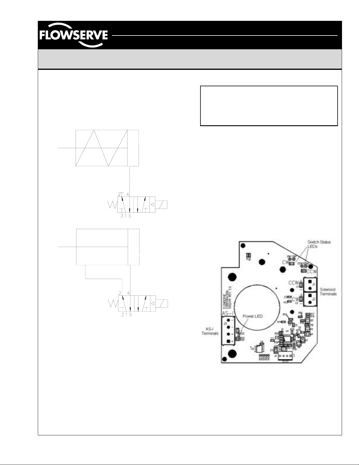
Spool and Tubing Configuration
1. For external solenoid valves, refer to solenoid
valve operating instructions for piping and tubing
configuration. For integrated solenoid valve, a
four-way spool valve is provided. Plug port #2
for 3-way applications (Figure 1). Make sure the
plug is properly configured before installing
tubing.
2. Make sure all air pressure is removed before
installing tubing.
3. Attach tubing according to solenoid valve
manufacturer’s instructions. For integrated
solenoid valve configuration, refer to Figure 1 for
AXAIM025-00 (AUTO-87) 7/01 Page 1 of 4
©2001, Flowserve Corporation, Provo, UT
Page 2
Automax Valve Automation Systems
Installation, Operation and Maintenance Instructions
Flowserve Corporation 765 South 100 East Phone: 801 373 3028
Flow Control Division Provo, Utah 84606 Facsimile: 801 489 2228
Automation Business Unit www.flowserve.com Email: actuators@flowserve.com
spring return or Figure 2 for double acting
applications. Attach supply tubing to Port 1 and
use 3 and 5 for exhaust.
4. To prolong actuator life use only clean, dry plant
air. Lubricated air is not required, although it is
recommended, particularly for high cycle
applications.
Figure 1
Electrical Connections
CAUTION
To prevent ignition of hazardous atmospheres,
keep cover bolts tight while circuits are live.
Disconnect supply circuit before opening.
Entry into the BUSwitch™ integrated solenoid
housing is made through three ½” NPT conduit
entries. UltraSwitch enclo sures feature two entries:
¾” NPT for XL and PL series and ½” NPT for GL
series. Figure 3 pro vides terminal locations on the
XA0244 interface card.
Connection of the data cable is made to connector
P3 - observing polarity. Incorrect polarity will not
damage the electronics, but it will prevent
communication. Caution: make sure power is
turned off when making electrical connection.
For hazardous locations, Underwriters Laboratories
(UL) and the National Electric Code (NEC) require
an approved sealing f itting within eighte en inches of
the switch enclosure.
Figure 2
Lubrication
All BUSwitch™ integrated spool valves are prelubricated and will operate dry (with no additional
lubrication). The use of lubricated air will not
interfere with the functioning of the BUSwitch™. If
air lubrication is used, the oils listed below are
popular, easily obtainable, fluids that are
recommended for use with the BUSwitch
integrated spool valve: Gulf Harmon y 47, Mobil DTE
Medium, Shell T ellus 29, Texaco Rondo B, Soh ivis
47 and Sunnis 921. Many other lubricants are
acceptable providing they do not contain det ergents
that will attack Buna N or Viton Seals.
AXAIM025-00 (AUTO-87) 7/01 Page 2 of 4
©2001, Flowserve Corporation, Provo, UT
Solenoid to AS-I Interface Card (XA0244 rev 2.0)
Figure 3
Open conduit entries must be closed after
installation using a close-up plug approved for
hazardous locations. Conduit and plugs must fully
engage five threads.
Page 3

Automax Valve Automation Systems
Installation, Operation and Maintenance Instructions
Flowserve Corporation 765 South 100 East Phone: 801 373 3028
Flow Control Division Provo, Utah 84606 Facsimile: 801 489 2228
Automation Business Unit www.flowserve.com Email: actuators@flowserve.com
Special Notes on AS-I cabling
Minimum voltage r equirement for the BU Switch™ is
29.5 VDC supply. The output volt age of the fiel dbus
power supply, the current drawn and the electrical
characteristics of the data cable determine the
maximum distance that a particular segment can
span. With data cable that conforms to the AS-I
cable specified in s ection 5.5.3 of AS-I sp ecification
V2.0 distances of 100 m are guaranteed. If a
shielded cable is used, c onnect the shield to gr ound
at one point only. Multiple grounds can lead to
ground loops whic h can impair the pr oper operation
of the segment. For this r eason, a shield c onnec tion
has not been provided inside the BUSwitch™
housing. Radio frequency grounding at multiple
points through the use of capacitors is not allowed
by the AS-I protocols. For a more thorough
treatment of data cable wiring and aspects of
installation refer to the AS-I specification V 2.0.
Device Initialization
Each new device that is connected to the AS-I
network is recognized within 10ms. Devices are
immediately ready for use when an address is
assigned. Make sure each device to be connected
to a bus segment has a unique address prior to
starting configuration software. This will ensure that
each device is recognized by the system. Duplicate
addresses can result in devices not being
recognized.
Pneumatic Actuator Operation – Single
Coil, Fail Open or Fail Closed
For operation requiring a consistent fail position
(either open or closed), One output is used as
shown in the Single Coil T r uth Table. To reverse the
actuator fail mode for double acting actuators,
reverse actuator ports. To reverse spring-return
actuators, actuator modification is necessary.
Single Coil Truth Table
Output 1 OPEN/CLOSE
0 De-energized
1 Energized
Pneumatic Actuator Operation – Dual
Coil, Fail in Last Position
Dual Coil Operation uses both o utput 1 an d output 2
as shown in the Dual Coil Truth Table.
movement to take place, the Output parameters
must take on opposite values as shown below.
Dual Coil Truth Table
Output 1 Output 2
0 0 No Change No Change
1 0 Energized De-energized
1 1 No Change No Change
0 1 De-energized Energized
OPEN CLOSE
For valve
Adjustment of Switch Cams
1. Loosen five captive cover screws and
remove lid, turning slightly while lifting.
2. Place the actuator in the clock-wise
(CW) position and connect to the ASI bus segment.
3. Push down on the top cam until it
clears the splined coupler, rotating
clockwise until the CW LED is
illuminated (figure 4).
4. Release the cam and insure that it
fully engages the spline.
5. Place the actuator in the counterclockwise (CCW) position.
Figure 4
6. Pull up on the lower cam until it
clears its splined coupler, rotating
counter-clockwise until the CCW LED is
illuminated (figure 4).
AXAIM025-00 (AUTO-87) 7/01 Page 3 of 4
©2001, Flowserve Corporation, Provo, UT
Valve Position Monitoring and Reporting
The BUSwitch™ monitors the status of two limit
switches. SW 1 is the upper switc h and is set to tr ip
when the valve reaches the c losed pos ition. SW 2 is
the lower switch and is s et to trip when the valve is
open.
Truth Table for Switch Values
SW1 SW2 Input 1 Input
2
A A 1 1 Improper switch adj.
A O 1 0 Actuator CLOSED
O A 0 1 Actuator OPENED
O O 0 0 Actuator is moving
A = Activated or Tripped, O = Open or Not Tripped
Meaning
Page 4

Automax Valve Automation Systems
Installation, Operation and Maintenance Instructions
Flowserve Corporation 765 South 100 East Phone: 801 373 3028
Flow Control Division Provo, Utah 84606 Facsimile: 801 489 2228
Automation Business Unit www.flowserve.com Email: actuators@flowserve.com
This page intentionally left blank
AXAIM025-00 (AUTO-87) 7/01 Page 4 of 4
©2001, Flowserve Corporation, Provo, UT
 Loading...