

Page 1

DESCRIPTION
Worcester Controls/McCANNA ACCESS I and M Series 39 actuators
are pneumatic quarter-turn valve actuators. The solenoid and limit
switches for the ACCESS I are integral to the actuator end cap, while
the ACCESS M is a separate factory-mounted enclosure containing
the solenoid and limit switches. The design utilizes a double-rack,
single-pinion concept, with each rack integrally cast to a piston. Both
pistons are supported and centered by large, stainless steel guide
rods. In double-acting units, both pistons are pressurized on both
strokes of the actuator. Ambient temperature range of ACCESS unit is
0°F minimum to 160°F maximum.
Standard units feature an extended top shaft for manual override
capabilities and a completely modular design which allows simple
attachment of a variety of accessories. The units feature a control
block (with spool valve) which properly directs supply air to the
actuator. The control block provides independently adjustable speed
control for both opening and closing strokes of the actuator on
double-acting units, and for the closing stroke on spring-return units
(standard mounting configuration). The units can also be supplied
with an air connection block (in place of control block) for when there
is no solenoid valve integral with unit.
a WARNING: SERIES 39 ACTUATORS ARE ELECTRO-MECHANICAL
DEVICES SUBJECT TO NORMAL WEAR AND TEAR. ACTUATOR LIFE IS
DEPENDENT UPON APPLICATION AND ENVIRONMENTAL
CONDITIONS. IF APPLIED IN HAZARDOUS SERVICES, SUCH AS BUT
NOT LIMITED TO MEDIA TEMPERATURE EXTREMES, TOXINS,
FLAMMABLES, OR OTHER SERVICES WHERE IMPROPER OR
INCOMPLETE OPERATION COULD PRODUCE A SAFETY HAZARD, IT IS
INCUMBENT UPON THE SYSTEM DESIGNER AND THE USER TO
PROVIDE PROPER WARNING DEVICES SUCH AS TEMPERATURE
SENSORS, OXYGEN SENSORS AND FLOW SENSORS. FLOWSERVE
ALSO RECOMMENDS THAT THE INTEGRAL LIMIT SWITCHES BE USED
FOR MONITORING AND/OR ELECTRICAL INTERLOCK.
CAUTIONS: When actuator is installed in outdoor conditions, water
can enter the exhaust hole(s) of the control block or air connection
blocks, and then freeze. Flowserve suggests a cover be used, or
mount the actuator such that the block exhaust hole(s) will not fill
with water.
Flowserve recommends that all products which must be stored
prior to installation be stored indoors, in an environment suitable
for human occupancy. Do not store product in areas where
exposure to relative humidity above 85%, acid or alkali fumes,
radia tion above normal background, ultraviolet light, or
temperatures above 120°F or below 40°F may occur. Do not store
within 50 feet of any source of ozone.
IMPORTANT: INCLUDED IN ALL 39 ACTUATOR ACCESSORY AND
REPAIR KITS IS A REBUILD/ACCESSORY ADDITION LABEL, WHICH
IS TO BE MARKED WITH A PERMANENT MARKER AND THEN
APPLIED TO THE ACTUATOR AFTER AN ACCESSORY KIT HAS BEEN
INSTALLED OR AN ACTUATOR HAS BEEN REPAIRED.
All ACCESS M units have four threaded tamper proof plugs installed
over the enclosure mounting machine screws. No attempt should be
made to remove these plugs. If it becomes necessary to remove
enclosure from actuator end cap, consult Flowserve.
INSTALLATION
NOTE: The Series 39 actuator is normally installed with its major axis
parallel to the pipe line (this is mandatory when mounting actuator to
90° V1 diverter/three-way (D44 & T44) valves and CPT valves. The
actuator can be oriented above, beside or beneath the valve without
affecting its operation.
Sizes 10–35 Rev. R6 actuators may come with an ISO locating ring
used for optional ISO mounting.
A. Determine mode of operation desired (normally open or normally
closed) of the valve.
B. Determine desired quadrant for bracket attachment and direction
of mounting of actuator (in-line or cross-line).
C. Attach mounting bracket to actuator using four (4) cap screws
and lockwashers provided in mounting kit. To avoid any damage
to the Series 39 actuator body, ONLY the proper length screws
supplied with the mounting kit should be used. For
1
/
4"– 2" top-
mount style valves, attach bracket such that bracket nameplate
will be to side of valve.
For mounting to 818/828 Series valves insert ISO locating ring
into groove on bottom of actuator before attaching to bracket.
FCD WCAIM2028-01
(Part 15908)
Worcester Controls 10, 15, 20 ACCESS I
and 10-40 ACCESS M 39 Actuators Intrinsically Safe
Installation, Operation and Maintenance Instructions
Page 2

2 10, 15, 20 ACCESS I and 10-40 Access M 39 Actuators Intrinsically Safe WCAIM2028
NOTE: Ring can be permanently held in groove by applying Loctite
to ring before inserting in groove.
D. Attach bracket/actuator assembly to valve as follows:
CAUTION: Ball valves can trap pressurized media in the cavity. If
it is necessary to remove any valve body bolts, stem nuts, or
remove valve from the line, and if the valve is or has been in
operation, make sure there is NO pressure to or in the valve and
operate valve one full cycle. However, the valves listed below
do not require the removal of any valve body bolts or removal of
valve from line in order to mount actuator.
1. Rotate valve ball and stem to position necessary to achieve
desired operation. If any valve information is marked on stop
plate or handle, it will be necessary to transfer this
information to the bracket nameplate
2. For
1
/
4"– 2" 44, and
1
/
2"– 2" WK70/WK74,
1
/
4"–1
1
/
2" 59 and
1
/
2"–1
1
/
2"
H71 Series top-mount style valves and
1
/
2"– 2" 51/52,
1
/
2"–1
1
/
2"
82/83 Series valves with high-cycle stem packing as standard,
remove handle nut, lockwasher, handle, separate stop plate (if
any), retaining nut and stop pin(s). Add the two additional
Belleville washers with their larger diameter sides touching
each other. Add the self-locking nut to the stem and tighten
while holding the stem flats with wrench. Tighten until
Belleville washers are flat, the nut will “bottom”, and then
back nut off
1
/
3 of a turn. The two additional Belleville washers
and the self-locking nut are included in the mounting kit.
CAUTION: The self-locking stem nut is difficult to tighten,
and must fully flatten Belleville washers before backing off.
For 2" 59, H71, 82/83, and 2
1
/
2" 45, 82/83 series valves, and
valves 3" and larger with square stem, remove handle
assembly (if any), retaining nut, stop and stop screws.
Replace with valve stem spacer or, if valve has graphite stem
packing, with two Belleville washers (except 8", 10" 82/83 and
10" 51/52), and replace retaining nut.
NOTE: Belleville washers are installed with their larger
diameter sides touching each other. Do not use stem spacer
when Belleville washers are used. Using a wrench to prevent
stem from turning, tighten retaining nut until stem packing is
fully compressed or Bellevilles, if used, are fully flattened,
then back off nut
1
/
6 turn. Excessive tightening causes higher
torque and shorter seal life.
NOTE: Large valves with V51 high-cycle stem packing option
installed, identified by two Belleville washers installed and
handle assembly, stop and stop screws removed, and
818/828 Series Valves do not require stem area disassembly.
For
1
/
2"– 2" 94 valves, remove handle (if any). Do not remove
gland plate or gland bolts.
For 3" and larger 94 and 2" and larger E818/828 valves,
remove handle assembly, stop, and spacer (if any). Do not
remove gland plate or gland bolts.
For 2" and larger 818/828 valves, remove handle assembly,
locking plates and hardware, and stop screw (if any). Do NOT
remove stop plate (2"– 6" sizes) or spacer (8" size).
3. Center coupling on valve stem.
4. Lower mounting bracket/actuator assembly over coupling and
onto valve, making sure that male actuator shaft engages slot
in coupling.
5. Secure bracket to valve using cap screws and lockwashers, or
bolts and nuts provided in mounting kit. Tighten securely. For
1
/
2"– 2" top mount style valves, bracket nameplate will be to
side of valve.
Install set screws (if any) in the coupling and tighten securely.
6. Determine if mode of operation is as desired; if not:
a. Double-Acting Actuators
- Mount the actuator 90° from
normal mounting (see last paragraph in D.6.b for size 25
and larger actuators). On 10–20 sizes, the actuator may
also be inverted, yielding the opposite mode.
b. Spring-Return Actuators
- The normal method of
mounting is to have the actuator in line with the pipe line
and the valve and actuator in the FAIL-CLOSED position.
For FAIL-CLOSED cross-line operation with 10–20 sizes,
invert actuator and cross-line mount actuator to pipe line.
For FAIL-OPEN in-line operation with 10–20 sizes, invert
actuator. (NOTE: If in-line coupling is used, actuator does
not need to be inverted). Rotate the valve ball and stem
90°, so coupling lines up with actuator shaft. Mount
actuator in line with the pipe line. See Electrical
Connection Section for proper wiring information.
For FAIL-OPEN cross-line operation with 10–20 sizes,
rotate the valve ball and stem 90°, so coupling lines up
with actuator shaft. Mount actuator cross line to pipe line.
See Electrical Connection Section for proper wiring
information.
On sizes 25 and larger double-acting and spring-return
actuators the output shaft is square. This allows selection
of either mode of operation by indexing the coupling
(including valve ball and stem) 90° to the actuator shaft,
while keeping the actuator in an in-line orientation. Crossline mounting, if desired, requires a special bracket,
except for the 818/828 Series valves.
7. Determine position indication. Buttons on position indicator
are set up to show valve closed on in-line mounting, i.e.,
pistons together in actuator. If different indication is required:
a) Check which visual indication is required.
b) Check that indicator, when located on actuator shaft, will
show correct indication.
c) To change indication, push out (remove) red and white
buttons and reassemble in opposite positions (this step is
only necessary on 10–20 sizes).
d) Locate indicator on actuator shaft flats. Press firmly until
location nibs snap into recess on actuator shaft.
Flow Control
Worcester Controls
Page 3
WCAIM2028 10, 15, 20 ACCESS I and 10-40 Access M 39 Actuators Intrinsically Safe 3
AIR SUPPLY AND
ELECTRICAL INSTALLATION
A. 1. Air Supply:
The Series 39 Actuator is factory lubricated. For optimum
operation, the use of filtered and lubricated air is
recommended.
2. Air Supply Pressure:
Intrinsically Safe versions of double-acting actuators require
40–100 psig supply air. Spring-return actuators require
80–100 psig supply air. Spring-return actuators can also be
set up to operate on supply air pressures ranging from 40–80
psig by using fewer springs. See “Rebuilding Instructions”,
Spring-Return Actuator, for proper number and location of
springs for reduced supply air pressures.
3. Air Supply Connection:
Connect air supply to
1
/
4" NPT connection on control block. For
units with no integral solenoid valve, air connection block has
two
1
/
4" NPT connections for inlet air (only one used for
spring-return units).
4. Recommended Tubing Sizes:
In order to provide sufficient flow of supply air to the Series
39 actuator, the following tubing sizes are recommended:
Actuator Size Runs Up To 4 ft. Long Runs Over 4 ft. Long
10, 15, 20, 25
1
/
8"
1
/
4"
30 and larger
1
/
4"
3
/
8"
5. Air Consumption:
The following chart shows the amount of pressurized (80
psig) air consumed per stroke in cubic feet. To determine the
total amount of air consumed per complete cycle for doubleacting actuators, simply add the volumes for both the opening
and closing strokes together; for spring-return units, the total
volume of air consumed is the volume shown for the opening
stroke.
Actuator Size
Stroke 1039 1539 2039 2539 3039 3339 3539 4039
Open .04 .08 .16 .28 .43 .65 .90 1.26
Close .05 .09 .17 .30 .47 1.10 1.27 1.43
6. Electrical Supply:
Make electrical connections in accordance with the wiring
diagram on the inside of cover or appropriate wiring diagram
in Section B.4.
7. Switch Ratings: 1 amp, 125 VAC
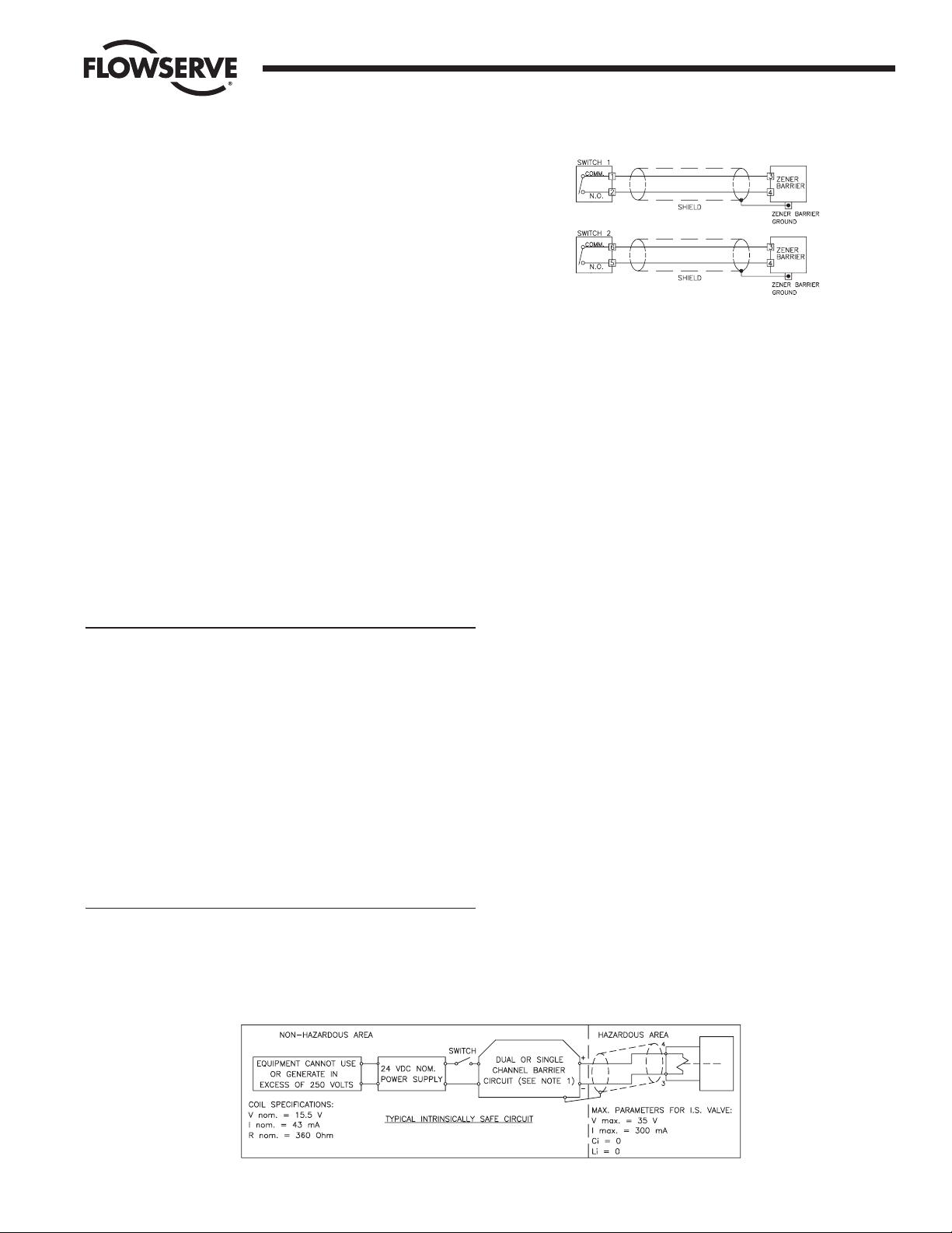
B. ELECTRICAL CONNECTION:
The intrinsically safe versions of the ACCESS I and ACCESS M will
be intrinsically safe when connected through CSA Certified zener
barriers rated 28 volts DC maximum, 300 ohms minimum (for
SW-1 and SW-2 only; refer to paragraph 4 of this section for
intrinsically safe wiring of solenoid), as shown in the wiring
diagrams (Figure 2) below.
IMPORTANT: Shielded cable must be used for each intrinsically
safe circuit (Switch circuits and solenoid circuit) and for zener
barriers, the shield must be connected to a zener barrier ground.
1. The “standard” mounting configuration of the 39 actuator to
the valve is in-line, fail-closed. In this configuration, SW-2, as
described in the wiring diagram and part 3, will give
indication when the actuator is in the closed position, or CW
limit of rotation. SW-1 gives indication of the open position,
or CCW limit of rotation (refer to the appropriate wiring
diagram in figure 2).
NOTE: The CW or CCW rotation of the actuator shaft is
determined when viewing the actuator from the nameplate
side of the actuator while being able to read the nameplate
from left to right.
2. Fail open configuration for sizes 10–20 may be obtained by
either inverting the actuator, using in-line coupling, or
mounting the actuator cross-line. For sizes 25 and larger the
coupling (including valve ball and stem) must be indexed 90°
to the actuator shaft. Refer to Installation Section D.6.b. In
these cases, SW-1 and SW-2 indication will be reversed from
the above but actuator rotation will vary, depending on which
fail-open mounting is used, and wiring shall be done per the
appropriate wiring diagram in figure 3.
Flow Control
Worcester Controls
Figure 1
Figure 2
Page 4
4 10, 15, 20 ACCESS I and 10-40 Access M 39 Actuators Intrinsically Safe WCAIM2028
3. Switches have been factory adjusted, but should be rechecked
after installation. Adjustment is as follows:
a) Switch adjustment for “standard” mounting:
With actuator mounted in “standard” mounting
configuration (see Step 1) set actuator in full-closed
position with the adjustment screw near its loose limit.
Adjust closed position switch SW-2 (see Wiring Diagram)
by tightening the adjustment screw until switch contacts
click. Then tighten adjustment screw one additional turn.
With air supply to actuator, energize solenoid, if applicable,
cycle to the full-open position and adjust open position
switch SW-1 in the same manner.
b) Switch adjustment for FAIL-OPEN mounting:
With actuator mounted in FAIL-OPEN mounting
configuration (see Step 2) set actuator in full-open position
with the adjustment screw near its loose limit. Adjust open
position switch SW-2 (see Wiring Diagram) by tightening
the adjustment screw until contacts click. Then tighten
adjustment screw one additional turn. With air supply to
actuator, energize solenoid, if applicable, cycle to the fullclosed position and adjust closed position switch SW-1 in
the same manner as SW-2.
4. Wiring instructions for solenoid and/or limit switches:
The Intrinsically Safe solenoid valve used in the ACCESS is
designed to operate on power levels compatible with Intrinsic
Safety requirements. They are Factory Mutual (FM) approved
for Class I, II and III Groups A, B, C, D, E, F, and G
applications. Entity Approval #OT4A6.AX (NFPA 493; July 19,
1990).
NOTE 1: For barrier interconnection, refer to maximum barrier
output parameters as referenced on the specific barrier
Installation drawing. Connect as follows:
a) V max > Voc of single or Vt of dual channel barrier.
b) I max > Isc of single or It of dual channel barrier
c) Ci + field wiring < Ca of single or dual channel barrier
d) Li + field wiring < La of single or dual channel barrier
For current and wattage values at various input voltages see
table below.
Input Voltage Current Wattage
15.5 VDC 43 mA .7
24 VDC 68 mA 1.63
35 VDC 95 mA 3.3
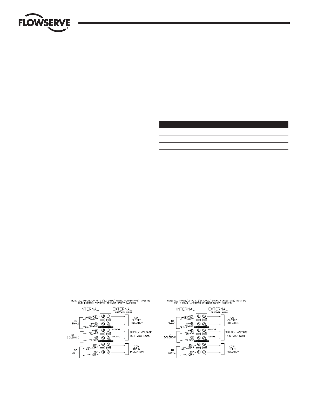
Make electrical connections in accordance with the
appropriate wiring diagram on inside of cover or the
appropriate diagram in figure 3:
NOTE 2: Installation of Intrinsically Safe Systems is to be done
in accordance with Canadian Electrical Code, Part 1 and
National Electrical Code, Chapter 1.
DEFINITIONS:
Ca-Maximum Allowed Capacitance Li-Maximum Internal Inductance
Ci-Maximum Internal Capacitance Voc-Maximum Output Voltage
I max-Maximum Input Current V max-Maximum Input Voltage
Isc-Maximum Output Current Vt-Voltage Total
La-Maximum Allowed Inductance
Flow Control
Worcester Controls
Figure 3
FAIL-CLOSED
(Sizes 10–40 in-line operation)
(Sizes 10–20 in-line, inverted operation)
FAIL-OPEN
(Sizes 25–40 cross-line operation)
Page 5
WCAIM2028 10, 15, 20 ACCESS I and 10-40 Access M 39 Actuators Intrinsically Safe 5
Flow Control
Worcester Controls
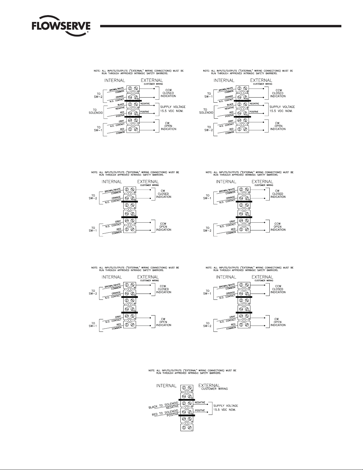
Figure 3 continued
FAIL-CLOSED
(Sizes 10–20 cross-line, inverted operation)
FAIL-CLOSED
(Sizes 10–40 in-line operation)
(Sizes 25–40 cross-line operation)
No solenoid
FAIL-OPEN
(Sizes 10–20 cross-line operation,
or with in-line coupling)
(Sizes 25–40 in-line operation)
FAIL-OPEN
(Sizes 10–20 in-line, inverted operation)
No solenoid
FAIL-CLOSED
(Sizes 10–20 cross-line,
inverted operation)
No solenoid
(Sizes 10–20 cross-line operation,
(Sizes 25–40 in-line operation)
SOLENOID/NO SWITCHES
FAIL-OPEN
or with in-line coupling)
No solenoid
Page 6

Figure 4
6 10, 15, 20 ACCESS I and 10-40 Access M 39 Actuators Intrinsically Safe WCAIM2028
NOTE 3: The wiring diagrams shown in figure 3 are for specific
actuator positions/operations. For switch indications of other
positions/operations the actuator should be operated, and SW-1 and
SW-2 checked to verify which switch will give the desired indication.
5. Place the lubricated O-ring down over the threaded section of
the housing onto the machined shoulder. The cover must be
threaded onto housing tightly for proper performance. The
assembly is now complete.
NOTE: For units with a metal cover, a light coat of grease (such
as a #1 grease) shall be applied to the cover threads. A minimum
of
1
/
3 the circumference of the threads to be lubricated.
OPERATION
A. Double-Acting with Control Block - Air is supplied to the 1/
4" NPT
port on the block. When the solenoid is energized, the springloaded plunger is withdrawn, allowing the supply air to shift the
spring-loaded spool within the block, which opens the supply
path to the center chamber of the actuator. Air from the end
chambers of the actuator is allowed to pass through the block
and exhaust to atmosphere.
When the solenoid is de-energized, the spring-loaded plunger
blocks the flow of air to the spool seal within the block and the
spool spring shifts the spool within the block to a position which
opens the supply path to the end chambers of the actuator. Air
from the center chamber of the actuator is allowed to pass
through the block and exhaust to the atmosphere.
The actuator is electrically fail-safe. That is, it will reurn to its deenergized position upon electrical failure.
Flow Control
Worcester Controls
Figure 5
Spring-return
Double-acting
Double-acting
Page 7

WCAIM2028 10, 15, 20 ACCESS I and 10-40 Access M 39 Actuators Intrinsically Safe 7
The unit has two independently adjustable speed control screws
which can be used to adjust the speed of operation for the
opening and/or closing stroke (see figure 4). If the speed control
screws are too tight, the unit will fail to operate.
NOTE: Speed control screws are shipped from the factory in the
full-open position.
B. Spring-Return with Control Block - Air is supplied to the 1/
4" NPT
port on the block. When the solenoid is energized, the springloaded plunger is withdrawn, allowing the supply air to shift the
spring-loaded spool within the block, which opens the supply
path to the center chamber of the actuator. Air from the end
chambers of the actuator is allowed to pass through the block
and exhaust to atmosphere.
When the solenoid is de-energized, the spring-loaded plunger
blocks the flow of air to the spool within the block and the springloaded spool returns to a position which allows air from the
center chamber of the actuator to pass through the block and
exhaust to atmosphere as the actuator is cycled by the springs in
the end chambers of the actuator. The end chambers are
exhausted to atmosphere at all times.
The actuator is fail-safe. That is, it will return to its de-energized
position upon electrical or pneumatic failure.
The unit has one speed control screw, which can be used to
adjust the speed of operation for the closing stroke (on a FAILCLOSED unit) or opening stroke on a fail open unit, and one port
plugged with a red plastic plug (see figure 4). If the speed control
screw is too tight, the unit will fail to operate.
Note: Speed control screws are shipped from factory in the full-
open position.
CAUTIONS: If converting a double-acting actuator to a springreturn actuator or vice-versa, be sure the correct control block
gasket is used and properly installed (see figure 5 and actuator
exploded view). Do not apply any grease to gasket, it must be
installed dry.
Be sure red plastic plug is installed in plugged port (see figure
4) for spring-return actuators.
C. Double-Acting with No Solenoid and No Control Block - Air is
supplied to the
1
/
4" NPT port on the air connection block to the
center chamber of the actuator through a remotely mounted fourway solenoid (or similar supply system). The other
1
/
4" NPT port
on the air connection block to the end chambers is exhausted
through solenoid (or similar supply system). When solenoid is
de-energized (energized) supply air is now supplied to end
chambers and center chamber is simultaneously exhausted
through solenoid.
D. Spring-Return with No Solenoid and No Control Block - Air is
supplied to the
1
/
4" NPT port on the air connection block to the
center chamber of the actuator through a remotely mounted
solenoid (or similar supply system). The other
1
/
4" NPT port on
the air connection block is the exhaust port for the end
chambers and may be exhausted to atmosphere or through
customer’s system.
When the remotely-mounted solenoid (or similar supply system)
blocks the supply air to the center chamber of the actuator, a
means must be supplied to exhaust this chamber and the actuator
is cycled by the springs in the end chambers.
E. Stroke Times
For stroke times of the ACCESS I and ACCESS M Series 39
actuators with solenoid and control block, consult factory. Times
will be measured in seconds and will represent average times
under 50% load conditions with an air supply pressure of 80
psig. Times will be per stroke for double-acting actuators. For
spring-return actuators, the opening stroke times may be slightly
longer; stroke times for the closing (spring) stroke will be
dependent upon the number of springs used.
Cycle times for customer air supply systems will be dependent
upon customer equipment.
F. Manual Operation
In the event of air failure, the ACCESS I and ACCESS M Series 39
actuators can be cycled manually. This is accomplished by
applying a wrench to the exposed top shaft of the actuator and
turning it in the desired direction.
a WARNING: Care must be taken to ensure that the actuator is
not operated automatically while manual operation is being
performed.
If a routine cycle check is to be performed on an actuator with a
control block, the actuator can be cycled manually by shifting
the spool valve within the control block. This can be done by
pushing the override button in the control block (see figure 4 on
page 6 for location of button). Care must be taken to hold the
spool valve in the desired position until the actuator has
cycled. Provided the air supply is still on, the actuator will
cycle to its original position as soon as the manually applied
pressure on the override button is released.
MAINTENANCE
CAUTION: The actuator must be isolated both pneumatically and
electrically before any maintenance activity is begun.
Periodic checks should be performed to make certain that all
fasteners remain tight. Care should be taken when tightening the end
cap retaining bolts since these fasteners are METRIC. All other
fasteners are UNIFIED IMPERIAL.
All actuators are supplied with sufficient lubrication for their normal
working life. If required, recommended lubrication for all standard
actuators is a #1 grease.
Depending upon the conditions under which the actuator must work,
such as extended-duty, non-compatible operating media or abnormal
operating conditions, periodic replacement of internal seals is
recommended. Repair kits containing all necessary seals can be
obtained through any authorized Flowserve Worcester/McCANNA
Controls distributor.
Flow Control
Worcester Controls
Page 8

8 10, 15, 20 ACCESS I and 10-40 Access M 39 Actuators Intrinsically Safe WCAIM2028
On spring-return actuators, the springs may need replacement after
extended duty since springs may fatigue and break. SPRINGS
SHOULD ALWAYS BE REPLACED IN COMPLETE SETS. Spring kits are
available through any authorized Worcester/McCANNA distributor.
SPARE PARTS
The following are recommended spare parts which should be kept on
hand for Series 39 pneumatic actuators:
Repair Kit(s) - Kits contain all necessary seals,
bearings and instructions.
Spring Kit(s) - For spring-return actuators.
TROUBLESHOOTING
BEFORE DISASSEMBLING ACTUATOR FOR ANY REASON, CONSULT
REBUILDING INSTRUCTIONS CONTAINED IN FOLLOWING SECTION.
A. If actuator does not function, check to ascertain:
1. That valve is free to rotate. This can be done as described
above in Manual Operation.
2. That actuator is the correct size.
3. That speed control screws or exhaust ports are not blocked.
4. That correct voltage is supplied to solenoid.
5. That sufficient air supply is available at inlet to control block.
Inlet pressure to control block should be at least 40 psig for
double-acting, 80 psig for spring-return (unless a reduced
spring complement is installed (fewer springs)). When
checking supply pressure, place gage in line at control block
inlet and monitor gage for unexpected pressure drops.
B. If proper voltage and air pressure have been verified and valve is
free, proceed as follows:
1. Turn on signal voltage. Check solenoid for clicking sound.
2. If no sound is detected, remove air pressure and turn off
signal voltage.
a) Carefully unscrew solenoid and solenoid stem from end
cap.
b) Reapply signal voltage and observe solenoid plunger. If it
does not retract, replace solenoid.
3. Manually override control block. If correct operation is not
obtained, replace the control block.
4. If control block and solenoid are operating correctly, proceed
to Section C below.
C. If the actuator functions but exhibits leakage, or power loss
accompanied by leakage, proceed as follows:
1. Check voltage. Voltage must be within 10% of the specified
voltage (low voltage will cause leakage out of the back of the
solenoid and burn out of the coil).
2. Check air supply. Be certain that no sharp air pressure drops
occur as unit is cycled. Loss of air pressure can cause
incomplete shifting of the spool valves, which results in
bypass leakage and substantial actuator torque losses.
3. If air supply and voltage are adequate, proceed as follows:
a) If leak is at solenoid exhaust port, replace the solenoid.
b) If leak occurs at exhaust ports in the block itself, the
trouble will be in either the spool valve in the block, or at
one of the piston seals of the actuator. A leaking piston
seal will usually leak on either cycle.
If the block is replaced and leakage continues from
the exhaust port, remove the actuator from the valve,
disassemble (per Rebuilding Instructions below) and
check the following:
1) Make sure that all internal porting is free and clear of
any obstructions. End caps, guide rods and the piston
with hole are air-transporting components.
NOTE: The most common problem encountered on 39
actuators is the improper replacement of the piston
with hole, relative to seals in end caps. (See Step 5)
2) Make certain that the actuator has lubrication, and
that there is no solidified grease between the pinion
and the piston racks.
a) If actuator has no lubrication, apply generous
amount of a #1 grease.
b) If solidified grease between the pinion and the
piston racks is present, clean, dry, regrease and
reassemble.
3) Verify that actuator pinion shaft and/or pistons are
not bound. If bound, reassemble per Rebuilding
Instructions.
4) If unit exhibits excessive amounts of backlash, check
teeth on piston racks for wear. If worn, replace piston
assemblies.
5) In spring-return actuators, check for misplaced or
broken springs. If springs are broken, check body
bore for scoring.
a) If springs are broken, replace springs. SPRINGS
SHOULD ALWAYS BE REPLACED IN COMPLETE
SETS.
b) If body bore is scored, replace it. Also, replace
piston O-rings (contained in repair kit).
6) If actuator is free, valve is free and control block (if
used) is shifting air properly, reassemble the actuator
and retest. If unit still fails to operate, consult
Flowserve.
REBUILDING INSTRUCTIONS
NOTE: For identification of all numbered parts discussed below,
consult exploded view of actuator.
After actuator has been repaired, mark rebuild label accordingly and
apply to actuator.
Flow Control
Worcester Controls
Page 9

WCAIM2028 10, 15, 20 ACCESS I and 10-40 Access M 39 Actuators Intrinsically Safe 9
ACTUATOR DISASSEMBLY
1. Disconnect the air supply and electrical service to the actuator.
2. Remove the actuator and its mounting bracket from the valve.
(See Caution note.)
CAUTION: Ball valves can trap pressurized media in the cavity.
Isolate the piping system in which the actuator/valve assembly
is mounted and relieve any pressure on the valve. For all the
valves listed in Installation Section D, the actuator bracket can
be removed without loosening or removing any valve body
bolts.
3. Remove the actuator bracket from the actuator to begin repair.
(Note orientation of removed bracket for easy reassembly.)
4. It is not necessary to remove the control block (7A) or air
connection block (7B) to rebuild actuator. However, if it becomes
necessary to remove the block, begin by removing the block bolts
(7D). Use care to retain the block gasket (9A, 9B or 9C).
5. Each end cap (5A & 5B) is aligned onto the body (1) over a
“foolproof pin”. This ensures that the end caps can only be
assembled to their respective end of the actuator. Remove all four
metric screws (5C) from and remove both end caps. Remove the
two bearings (6A) and O-rings (15A and 15B) from each end cap.
CAUTION: If the actuator is a spring-return model, first
remove two end cap screws diagonally opposite each other,
then lubricate the threads and under the head. Replace the
screws and repeat procedure for the other two screws. Do this
for each end cap, as this will aid reassembly. Now uniformly
loosen all four end cap screws on each end cap two to three
turns at a time, in sequence, to relieve preload of the springs.
On larger actuators with springs use caution when removing
end caps. End cap screws are long enough to allow springs to
relieve before disengaging.
After the screws are removed, gently pry off each end cap, being
careful not to damage the end cap O-rings.
6. The two piston guide rod (4) assemblies can now be removed
from each end of the body and disassembled by removing the
piston set screws (12). Do not interchange piston guide rods (4)
and their respective piston (3). For sizes 10–20 Rev. R6 actuators,
each guide rod and piston may be press fitted together (do not
use set screws) and cannot be disassembled. (To assist
reassembly, mark the body with a line on the side from which the
guide rod using the through-hole is removed). Remove all O-rings
(15B and 15C) and bearings (6B) from pistons (3).
7. The shaft (2A) on sizes 10–20 can only be removed after piston
assemblies are taken out. Remove the position indicator (17) (if
any), the shaft clip (15F) (not a reusable part!) (see Note) and the
stainless steel washer from the top of shaft. Then remove the
shaft through the larger opening in the bottom of the body. The
top bearing (15G) and the O-ring (15D) can now be removed.
Remove the two stainless steel washers (10–35 sizes only) and
thrust bearing (10) from the top of the shaft, the O-ring (15E),
and bearing (15H) from the bottom end.
NOTE: For size 40 model, only a single stainless steel washer is
used and thrust-bearing (10) is not used.
Sizes 25-40 have an anti-ejection ring (15J). This ring does not
have to be removed and it may or may not be included in repair
kits.
NOTE: Some actuators may be using a spiral ring type shaft clip
as shown below.
To remove this clip, engage the lower end of the ring with a flat blade
screwdriver. Using another flat blade screwdriver push the top end of
the clip in the opposite direction. As the clip I.D. expands lift the clip
from the shaft. The installation of a new clip would be the above steps
in reverse and ensuring that the edges of the clip are properly seated
in the shaft groove.
Flow Control
Worcester Controls
Figure 6
Figure 7
IMPORTANT: Note the relative location of the shaft teeth and the
piston assembly’s rack teeth. The above figure is viewed when
looking at the top of the actuator.
IMPORTANT: Align gear teeth on the shaft per Figure 6.
Page 10

10 10, 15, 20 ACCESS I and 10-40 Access M 39 Actuators Intrinsically Safe WCAIM2028
ACTUATOR REASSEMBLY
1. Be sure the actuator surfaces are clean and free of grit and
scratches. If the inside walls of the body are scored, or the guide
rod surfaces are scratched, the actuator will leak after rebuilding.
New parts should be obtained from the factory. Light tracking,
barely detectable to touch, is acceptable.
2. All rebuilding kit O-rings and bearings may now be installed.
Lubricate the standard actuator thoroughly with a #1 grease.
Apply a light film of grease to all O-rings. NOTE: “High-
temperature” actuators and O-rings must be lubricated with Dow
Corning #7 or other equivalent high temperature silicone or
graphite base grease. (Note that kits also contain some parts for
earlier revisions of actuators which will not be needed.)
3. Replace the two split-ring style bearings (6A) and one guide rod
O-ring (15B) in each end cap.
Replace the split-ring style bearing (6B) and guide rod O-ring(s)
(15B) into I.D. groove(s) in each piston (3). Install O-rings (15C)
onto pistons.
4. Replace O-ring (15E) and bearing (15H) (10–40 sizes only) on
the bottom of shaft. On the top of the shaft add the two
stainless steel washers (10–35 sizes only) with the thrust
bearing (10) between them.
NOTE: For size 40 model only, a single stainless steel washer is
used and thrust bearing (10) is not used. Locate the top bearing
(15G) and O-ring (15D) into the body. For sizes 10–35 Rev. R6
actuators, top bearing (15G) is flat, the same as and
interchan
geable with thrust bearing (10). Replace the shaft
through the larger opening in the bottom of the body.
For sizes 25 through 40 actuators, replace anti-ejection ring (15J)
in its groove on the shaft (2B), if removed.
5. Very carefully align the piston guide rod assemblies inside the
body. Keep the pistons square to the body. (This is very important
in the 30 39 actuator where steel set screws can cause internal
body damage if the piston assemblies “cock” inside the actuator
body.)
IMPORTANT: One piston guide rod assembly has a through-hole
drilled in it. It can be easily located by looking down the ends of
both guide rods. This piston assembly must be reassembled,
with its respective guide rod, opposite the nameplate on the
body, as it was removed.
6. Align the shaft so that the teeth on the shaft will “pick-up” the
piston assembly’s rack teeth when turning the top extension of
the shaft clockwise (CW). (See Figure 6.)
IMPORTANT: Proper 90° rotation can only be ensured if the shaft
teeth begin to mesh with the piston assembly’s teeth at the
“proper tooth” between these meshing gear pairs. (See Figure 6.)
7. To ensure proper meshing of teeth, move the shaft 15 to 20
degrees counter-clockwise (CCW) from its normal position when
the piston assemblies are located at the body ends (See Figure 7).
NOTE: The “normal position” of the shaft on 10-20 sizes is whe
n
the top flats are parallel to the main axis of the actuator body. On
the 25-40 sizes the teeth of the shaft will be on the left side of the
actuator when viewed from the ends of the actuator. (See Figure
6.)
8. With the piston assemblies in the body, gently push each piston
into the body. Turn the top shaft extension clockwise (CW). Do
not allow the pistons to “cock”.
At the proper point of engagement between the shaft and piston
assemblies, both piston assemblies will move toward the center
of the body when turning the top shaft extension of the actuator
clockwise (CW).
9. Once the shaft and pistons are properly engaged, ensure that
smooth movement and full closed operation can occur without
moving the pistons out of the actuator body. This is important!
10. Install O-ring (15A) into and replace the actuator end caps, (5A
and 5B), noting that the “foolproof” pin between the body and end
cap mates properly. For spring-return actuators, see spring
installation section before installing end caps.
NOTE: When installing the end cap O-rings, use a small amount of
a general purpose lubricant, such as petroleum jelly, to hold them
in place for ease of assembly and to avoid having them fall and
get pinched.
11. Replace the stainless steel washer over the top shaft extension.
12. VERY IMPORTANT: Install the NEW shaft clip (15F) into its mating
groove on the top shaft extension. (The removed shaft clip is not
to be reu
sed.)
Place the numbered side up on the shaft clip and be certain the
clip is fully seated in its groove. See Note in Step 7 of Actuator
Disassembly for installation of spiral ring type shaft clip (which
newer rebuilding kits will contain).
If control block (7A) or air connection block (7B) was removed:
Properly insert appropriate gasket (9A, 9B or 9C) between control
block or air connection block and end cap (see figure 4 and
actuator exploded view), and attach block securely to end cap. Do
not apply any grease to gasket, it must be installed dry.
13. Replace position indicator (17) (if any). See Section D.7 in
Installation Section for proper installation and to determine
position indication.
14. Mark Rebuild/Accessory Addition Label, if included in repair kit,
and apply to actuator.
Flow Control
Worcester Controls
Page 11

WCAIM2028 10, 15, 20 ACCESS I and 10-40 Access M 39 Actuators Intrinsically Safe 11
SPRING-RETURN ACTUATOR
1. IMPORTANT: When less than the standard number of springs are
used in each end cap, these springs should be positioned
according to the air supply figures below.
Size 10–40
70 psi - 8 springs - 4 per end cap Remove center spring
60 psi - 8 springs - 4 per end cap Remove center spring
50 psi - 6 springs - 3 per end cap Use 3 on a diagonal
40 psi - 4 springs - 2 per end cap Use 2 in opposite corners
The values listed below are for standard and less than the
standard air pressure as required per the ordering code.
NOTE: Maximum Operating Pressure Does Not Change.
Ordering Code 4 5 6 7 ( )
Supply Pressure (psi) 40 50 60 70 80
Actuator Size End of Spring Torque (in-lb)
10 35 55 75 75 95
15 65 105 145 145 185
20 125 195 265 265 335
25 210 330 450 450 575
30 340 535 730 730 920
33 680 1,070 1,460 1,460 1,850
35 850 1,330 1,815 1,815 2,300
40 1,500 2,240 2,980 2,980 3,740
2. If a spring-return actuator is being repaired due to a failed spring,
REPLACE all the springs in this actuator, as well as any other
parts which may have been damaged.
3. When replacing the springs in a spring-return actuator, place the
springs in the end cap pocket after thoroughly lubricating each
spring. Be generous with lubricant!
4. With the springs pointing up and the end cap on a solid surface,
place the actuator body over the springs and the proper end cap.
(Each end cap can only be mounted to just one end of the
actuator body, as there is a “foolproof” pin in the end cap which
aligns with a hole in the body.)
5. Force the body down and begin by engaging two end cap screws
(5C) by hand through the end cap. Take each end cap screw up in
SMALL and EQUAL turns. Once the end cap is temporarily
secured to the body, turn the actuator over to its normal position
and uniformly take up the four end cap screws. Uniformly load all
the springs to prevent any spring from buckling.
IMPORTANT: Locating nibs are permanently cast into the sizes 25
through 40 actuator piston face. The actuator springs must fit
over these locating nibs on the piston face. Care in following the
above instructions will ensure the proper alignment of the spring
in the actuator body — proper contact with the piston face and
end cap.
6. In a similar manner, as in the previous steps, replace the springs
in the other end of the actuator body.
Flow Control
Worcester Controls
Page 12

12 10, 15, 20 ACCESS I and 10-40 Access M 39 Actuators Intrinsically Safe WCAIM2028
Flow Control
Worcester Controls
ACCESS M EXPLODED VIEW
Page 13

WCAIM2028 10, 15, 20 ACCESS I and 10-40 Access M 39 Actuators Intrinsically Safe 13
Flow Control
Worcester Controls
ACCESS I AND 39 ACTUATOR EXPLODED VIEW
Page 14

14 10, 15, 20 ACCESS I and 10-40 Access M 39 Actuators Intrinsically Safe WCAIM2028
Flow Control
Worcester Controls
PARTS LISTING
ITEM QTY. DESCRIPTION ITEM QTY. DESCRIPTION
1 1 Actuator Body 12 2 Piston Set Screws (if any)
2A 1 Shaft (10-2039) 13 1 Conduit Plug – Not Shown on ACCESS I
2B 1 Shaft (25-4039) 14 Varies Springs – See Table on page 11
3 2 Pistons 15A 2 End Cap O-Rings
4 2 Guide Rods 15B 6 Guide Rod O-Rings
5A 1 ACCESS I End Cap or ACCESS M Enclosure 15C 2 Piston O-Rings
5B 1 End Cap 15D 1 Top Shaft O-Ring
5C 8 End Cap Screws (Metric) 15E 1 Bottom Shaft O-Ring
5D 1 Cover “Z” 15F 1 Shaft Clip
5E 1 Caution Nameplate “Z” 15G 1 Top Pinion Bearing
5F 1 Cover “W” 15H 1 Bottom Pinion Bearing
5G 1 O-Ring – Cover 15J 1 Anti-Ejection Ring (Sizes 25–40)
5H 1 ACCESS M Endcap 16 1 Wiring Diagram – Not Shown
5J 1 Caution/Wiring Label “W” 17 1 Position Indicator
6A 4 Cap Bearing (Split-Ring Style) 18 2 Drive Screw
6B 2 Piston Bearing (Split-Ring Style) 19 2 Probes
7A 1 Control Block Assembly 20 2 O-Rings – Probe
7B 1 Air Connection Block (No Solenoid) 21 4 Washers – Probe (ACCESS I only)
7C - Not Used 22 2 Retaining Clips – Probe (4 for ACCESS M)
7D 4 Block Bolts 23 2 Spring – Probe (ACCESS I only)
8A 1 Solenoid Assembly 24 1 Terminal Strip
8B 2 Solenoid Exhaust Port Fittings 25 2 Mounting Screws – Terminal Strip
8C 1 Solenoid Exhaust Tubing 26A 1 Limit Switch Assembly – left
8D 1 Solenoid Adapter 26B 1 Limit Switch Assembly – right
8E 2 O-Rings 27 4 Mounting Screws – Limit Switch
9A 1 Gasket – Control Block (Double-Acting) 28 2 Switch Adjustment Screw
9B 1 Gasket – Control Block (Spring-Return) 29 2 Switch Adjustment Spring
9C 1 Gasket – Air Conn. Block (No Solenoid) 30 2 Terminal Strip Dividers
10 1 Thrust-bearing 31 1 Exhaust Port Plug (If No Solenoid)
11 1 Nameplate
To order proper parts, please specify the actuator size, model, and revision number. Use the standard nomenclature listed above.
The rebuilding kits include Items 15A through 15H, 6A and 6B, 10, and S.S. washers. Color of some replacement parts, such as bearings, may
vary from the parts removed.
ADDITIONAL PARTS LISTING (For ACCESS M only)
ITEM QTY. DESCRIPTION ITEM QTY. DESCRIPTION
32 2 Drive Screws 38 2 Flat Washer – Switch
33 1 Bracket-Switch 39 2 Upper Mounting Screw – Enclosure (11/
8" Long)
34 3 Mounting Screws – Switch Bracket 39A 2 Lower Mounting Screw – Enclosure (1" Long)
35 2 Retaining Ring – Switch 40 1 Gasket
36 2 Button – Switch 41 1 Nameplate
37 2 Spring – Switch 42 4 Threaded Tamper Proof Plug
Page 15

WCAIM2028 10, 15, 20 ACCESS I and 10-40 Access M 39 Actuators Intrinsically Safe 15
Flow Control
Worcester Controls
This page intentionally left blank.
Page 16

Flow Control
Worcester Controls
Flowserve Corporation has established industry leadership in the design and manufacture of its products. When properly selected, this Flowserve product is designed to perform its intended function
safely during its useful life. However, the purchaser or user of Flowserve products should be aware that Flowserve products might be used in numerous applications under a wide variety of industrial
service conditions. Although Flowserve can (and often does) provide general guidelines, it cannot provide specific data and warnings for all possible applications. The purchaser/user must therefore
assume the ultimate responsibility for the proper sizing and selection, installation, operation, and maintenance of Flowserve products. The purchaser/user should read and understand the Installation
Operation Maintenance (IOM) instructions included with the product, and train its employees and contractors in the safe use of Flowserve products in connection with the specific application.
While the information and specifications contained in this literature are believed to be accurate, they are supplied for informative purposes only and should not be considered certified or as a guarantee of
satisfactory results by reliance thereon. Nothing contained herein is to be construed as a warranty or guarantee, express or implied, regarding any matter with respect to this product. Because Flowserve
is continually improving and upgrading its product design, the specifications, dimensions and information contained herein are subject to change without notice. Should any question arise concerning
these provisions, the purchaser/user should contact Flowserve Corporation at any one of its worldwide operations or offices.
For more information about Flowserve Corporation, visit www.flowserve.com or call USA 1-800-225-6989.
FLOWSERVE CORPORATION
FLOW CONTROL
1978 Foreman Drive
Cookeville, Tennessee 38501 USA
Phone: 931 432 4021
Facsimile: 931 432 3105
www.flowserve.com
© 2005 Flowserve Corporation, Irving, Texas, USA. Flowserve and Worcester Controls are registered trademarks of Flowserve Corporation. FCD WCAIM2028-01 5/05 Printed in USA.
 Loading...