

Page 1

®
DECESPUGLIATORE BL FBS 25 A1
DECESPUGLIATORE
Traduzione delle istruzioni d’uso originali
PETROL TRIMMER
Translation of the original instructions
ROÇADEIRA A GASOLINA
Tradução do manual de instruções original
BENZIN-SENSE
Originalbetriebsanleitung
IAN 280454
Page 2

Prima di leggere aprire la pagina con le immagini e prendere confidenza con le diverse funzioni
dell’apparecchio.
Antes de começar a ler abra na página com as imagens e, de seguida, familiarize-se com todas as
funções do aparelho.
Before reading, unfold the page containing the illustrations and familiarise yourself with all functions of the
device.
Klappen Sie vor dem Lesen die Seite mit den Abbildungen aus und machen Sie sich anschließend mit allen
Funktionen des Gerätes vertraut.
IT / MT Traduzione delle istruzioni d’uso originali Pagina
PT Tradução do manual de instruções original Página
GB / MT Translation of the original instructions Page
DE / AT / CH Originalbetriebsanleitung Seite
5
28
50
71
Page 3
22
A B C D E F G H I J
B C D E F G H I J
21
3
4
5 6
3
4
7
19202122
8
9
2
1
18
20
19
14
13
10
11
12
15
16
17
23
24 25
29
28
26
27
9
44
15
Page 4
11
D E F G H I J
C D E F G H I J
E F G H I J
G H I J
H I J
F G H I J
1310
303114
32
3
4
10
27
33
43
25
34
7
18
4
17 36 1837
202122
98
10
10
35
26
19
36
Page 5

Contenuto
M TI T
Introduzione ................................. 5
Uso previsto ................................... 6
Descrizione generale ...................... 6
Volume di fornitura ...............................6
Descrizione
delle funzionalità .................................6
Illustrazione .........................................6
Funzioni di sicurezza............................7
Dati tecnici ..................................... 7
Norme di sicurezza ........................ 8
Simboli riportati
nelle istruzioni .....................................8
Simboli collocati sull’apparecchio ..........8
Norme di sicurezza generali .................9
Ulteriori regole di sicurezza ................12
Montaggio ................................... 13
Montaggio del rivestimento
di protezione .....................................13
Montaggio del tubo composto
da due parti ......................................13
Montaggio impugnatura
antivibrazione ...................................14
Messa in funzione ........................ 14
Rifornimento di carburante .................14
Avvio del motore ...............................16
Utilizzo ........................................ 17
Indicazioni d’uso ...............................17
Tosatura di erba ................................18
Prolungamento del lo ........................18
Vibrazioni dell’apparecchio ................18
Manutenzione e cura.................... 18
Pulitura dell’apparecchio ..................... 19
Sostituzione della bobina ...................19
Pulizia del ltro dell’aria .....................19
Sostituzione/regolazione
della candela di accensione ................ 19
Aflare dispositivo di taglio del lo ...... 20
Sostituzione ltro carburante .............. 20
Regolazione del carburatore ...............21
Intervalli di manutenzione ...................21
Magazzinaggio ............................ 22
Indicazioni generali
relative al magazzinaggio ..................22
Magazzinaggio in intervalli
di non utilizzo ................................... 22
Trasporto ..................................... 23
Smaltimento/Tutela dell’ambiente 23
Ricambi/accessori ........................ 24
Garanzia ..................................... 25
Servizio di riparazione ................. 26
Service-Center .............................. 26
Importatore ................................. 26
Ricerca guasti............................... 27
Traduzione della dichiarazione di
conformità CE originale ..................99
Vista esplosa ........................100/101
Introduzione
Congratulazioni per l’acquisto del Suo
nuovo apparecchio. Ha scelto un prodotto
altamente pregiato.
Questo apparecchio è stato sottoposto a
un controllo di qualità durante la produzione e quindi sottoposto a un controllo
nale. Quindi è garantito il funzionamento
del vostro apparecchio.
Le istruzioni per l’uso costituiscono
parte integrante di questo prodotto.
Contengono indicazioni importanti
per la sicurezza, l’uso e lo smaltimento. Prima dell’uso del prodotto,
si raccomanda di familiarizzare
con tutte le indicazioni di comando
e di sicurezza. Usare il prodotto
solo come descritto e per i campi
d’impiego specicati. Conservare le
istruzioni in un luogo sicuro e consegnare la documentazione in caso di
cessione del prodotto a terzi.
5
Page 6

I T M T
Uso previsto
Il decespugliatore FBS 25 A1 è adatto per
tagliare erba nei giardini, lungo i bordi
delle aiuole e intorno ad alberi o a pali di
recinto.
Qualsiasi altro uso, non indicato esplicitamente in queste istruzioni d’uso, potrebbe
danneggiare l’apparecchio e rappresentare
un serio pericolo per l’utente. L’apparecchio
non è previsto per tagliare cespugli, piccoli
alberi o piante similari.
L’apparecchio può essere usato soltanto da
adulti. I giovani di età superiore ai 16 anni
possono usare l’apparecchio soltanto sotto
la sorveglianza degli adulti. Il produttore
non si assume alcuna responsabilità per
eventuali danni dovuti ad un uso contrario
alle prescrizioni o ad un uso errato.
Descrizione generale
Le immagini si trovano sulle pagine
pieghevoli anteriori e posteriori.
Volume di fornitura
Rimuovere prima l’apparecchio dalla confezione e controllare che questo sia completo. Smaltire il materiale di imballaggio
secondo le disposizioni.
• Alloggiamento motore con tubo supe-
riore e impugnatura multifunzione
• Tubo inferiore con bobina lo montata
• Rivestimento di protezione
• Impugnatura antivibrazione con protezione gambe
• Tracolla con protezione corpo
• Chiave di manutenzione
• 2 tempo olio 100 ml
• acone miscela benzina/olio 500 ml
• Istruzioni per l’uso
Descrizione
delle funzionalità
Il decespugliatore, che viene condotto a
mano ed è trasportabile, possiede come
propulsore un motore a combustione interna che durante il lavoro è ininterrottamente
in funzione. La trasmissione di forza energetica avviene mediante un disco della frizione, che attraverso un innesto centrifugo,
nel momento in cui il numero di giri è alto,
trasmette la potenza del motore al dispositivo di taglio.
L’apparecchio possiede come dispositivo di
taglio un rocchetto portalo doppio, che è
provvisto di un tocco automatico. Durante
il procedimento di taglio i due li in materiale plastico girano intorno ad un’asse
verticalmente al livello di taglio.
Per permettere di proteggere l’utente, l’apparecchio è dotato di un dispositivo di protezione che copre il dispositivo di taglio.
La funzione degli elementi di regolazione
possono essere appresi nelle descrizioni
che seguono.
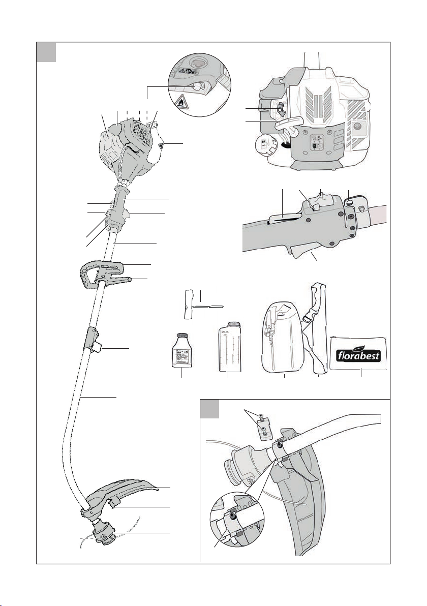
Illustrazione
1 Alloggiamento motore
2 Candela
3 Leva comando starter
4 Impugnatura avviamento
5 Pompa carburante (Primer)
6 Coperchio ltro dell’aria
7 Serbatoio carburante
8 Impugnatura centrale
9 Grilletto comando acceleratore
10 Tubo superiore
11 Impugnatura antivibrazione
12 Protezione gambe
13 Vite di ssaggio tubo
14 Tubo inferiore
15 Rivestimento di protezione
16 Dispositivo taglialo
6
Page 7

M TI T
B
C
D
E
F
H
I
J
L
M
17 Capsula portabobina
18 Bobina lo (non a vista)
19 Occhielli per tracolla
20 Interruttore on/off
21 Pulsante di arresto
dell’acceleratore
22 Bloccaggio di sicurezza
acceleratore
23 Chiave di manutenzione
24 2 tempo olio 100 ml
25 acone miscela benzina/
olio 500 ml
26 Protezione corpo
27 Tracolla
44 borsa degli attrezzi
28 2 viti del coperchio di protezione
29 Sostegno asta
30 Cappuccio di protezione trasporto
31 Pulsante di sicurezza
asta tubolare
32 4 viti manico antivibrazioni
33 Sostegno manico antivibrazioni
34 Tappo del serbatoio
45 Intaccatura del rocchetto
portalo
46 Scanalatura del
rocchetto portalo
Funzioni di sicurezza
22 Blocco leva
dell’acceleratore
Questo impedisce un’accele-
razione fortuita del motore. La
leva dell’acceleratore può essere
azionata soltanto nel momento
in cui è premuto il blocco leva
dell’acceleratore.
20 Interruttore di accensione/
spegnimento
Con l’interruttore di accensione/
spegnimento si spegne il motore.
Per riavviare il motore, portare
l’interruttore in posizione
15 Rivestimento di protezione
Questo dispositivo protegge
l’utente da contatti involontari
con l’utensile da taglio e fornisce
protezione dai corpi estranei
scaraventati.
.
43 Linguetta del dispositivo
di rilascio rapido
35 Viti di ssaggio
del rocchetto portalo
36 Occhiello di uscita lo
37 Molla del rocchetto portalo
38 Vite coperchio ltro dell’aria
39 Alloggiamento ltro dell’aria
40 Filtro dell’aria
41 Candela
42 Filtro del carburante
Dati tecnici
Decespugliatore .................... FBS 25 A1
Motore Motore a due tempi con un cilindro
Miscela di carburante .................... 50:1
Cilindrata del motore ................25,4 cm
Massima potenza
del motore ..................0,75 kW (1,1 CV)
Numero giri motore a vuoto ... 2800 min
Massimo numero di giri
dell’alberino ......................... 8500 min
Capacità del serbatoio .........650 ml/cm
Peso (serbatoio vuoto) ...................5,9 kg
Filo
Circonferenza di taglio ...........380 mm
Spessore del lo ........................2 mm
3
-1
-1
3
7
Page 8

I T M T
Lunghezza del lo .........................5 m
Livello di pressione acustica
(L
) .................. 98,2 dB(A), KpA= 3 dB
pA
Livello di potenza sonora (L
WA
)
garantito ............................ 110 dB(A)
misurata ......... 108,2 dB(A); K
Vibrazione (a
) .12,93 m/s2; K= 1,5 m/s
h
= 3 dB
WA
I valori di livello sonoro e delle vibrazioni
sono stati stabiliti in conformità con le norme e disposizioni indicate nella Dichiara-
zione di Conformità.
Norme di sicurezza
Per poter azionare l’apparecchio,
vanno seguite attentamente tutte le
istruzioni e informazioni relative
alla sicurezza, all’assemblaggio
e al funzionamento indicate nelle
istruzioni per l’uso. Tutte le persone
che azionano questo apparecchio
o sul quale eseguono lavori di manutenzione, devono conoscere le
istruzioni per l’uso ed essere informate sui potenziali pericoli.
Simboli riportati
nelle istruzioni
Simboli di pericolo con indica-
zioni relative alla prevenzione
di danni a cose e persone.
Simboli collocati
sull’apparecchio
Sull’apparecchio si trovano indicazioni sot-
to forma di simboli. Tali simboli forniscono
delle informazioni importanti sul prodotto
2
o indicazioni relative all’uso.
• Attenzione: sono necessarie particolari
misure di sicurezza al momento dell’uso dell’apparecchio!
• Prima dell’utilizzo devono essere lette
tutte le istruzioni per l’uso. L’inosservanza delle indicazioni sull’uso può
rappresentare un pericolo di vita!
Leggere attentamente le istruzioni per l’uso prima dell’utilizzo
dell’apparecchio.
Indossare dispositivi di protezione per occhi.
Indossare dispositivi di protezione per testa.
Indossare dispositivi di protezione per udito.
Indossare guanti di protezione.
Pericolo di ferite da taglio!
Indossare scarpe di sicurezza
con suola resistente.
Simboli di divieto con indicazioni
relative alla prevenzione di danni.
Simboli di avvertenza con infor-
mazioni relative ad un uso corretto
dell’apparecchio.
8
Accertarsi che, nel momento in
cui l’apparecchio è acceso o
mentre lo si sta impiegando, la
testa falciante non venga in contatto con corpi estranei.
Mantenere una distanza di sicurezza da terzi di minimo
15 metri.
Page 9
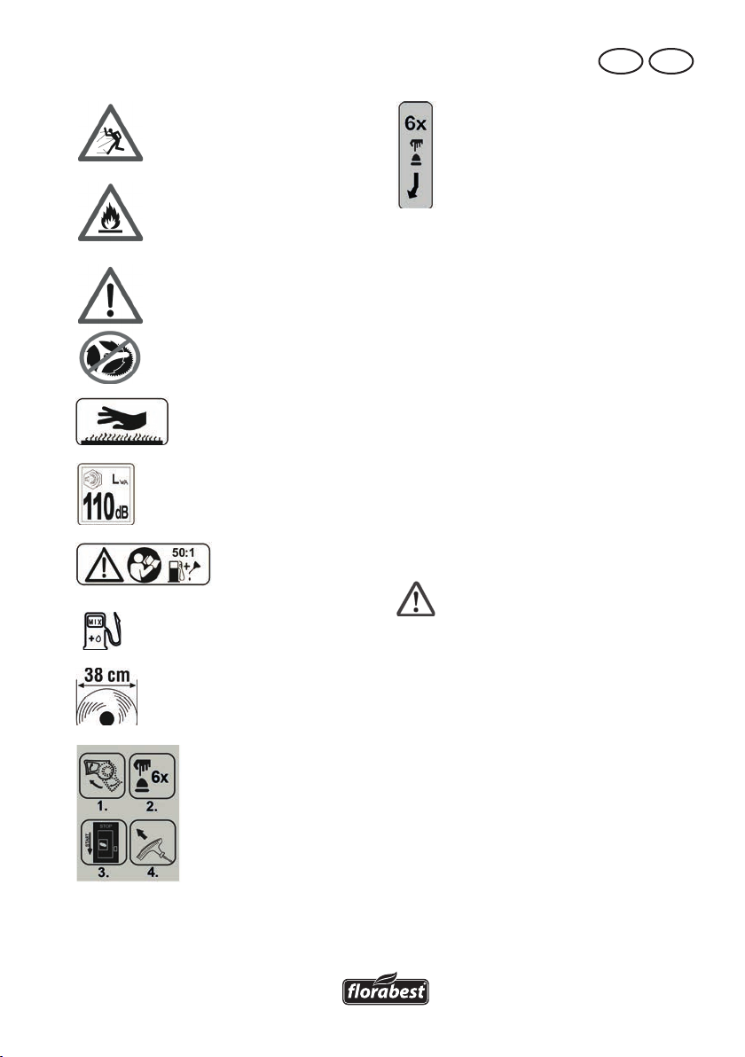
Pericolo a causa di parti catapultate! Tenere lontane altre persone.
Attenzione! Carburante e vapori
di carburante sono inammabili. Pericolo di incendio ed esplosione!
Attenzione! Lavorare solo con
una bobina lo.
Non usare lame falcianti di
metallo o lame per segatrici.
Pericolo di lesioni!
Attenzione superci bollenti,
pericolo di ustioni!
Indicazione sul livello di potenza
sonora L
Usare SOLTANTO
miscela carburante
Diametro di taglio
in dB.
WA
Rapporto di miscela
50:1, usare SOLTANTO miscela carburante.
M TI T
Pompa carburante (Primer)
Norme di sicurezza generali
L’uso dell’apparecchio va vietato a bambini nonché a persone malate e gracili. I
bambini devono essere tenuti scrupolosamente sotto sorveglianza quando questi
si trovano in zone in cui si trovano degli
apparecchi. Osservare le prescrizioni di
sicurezza regionali e locali vigenti nel
proprio paese. Ciò vale anche per tutte le
disposizioni di protezione e di tutela della
salute sul posto di lavoro.
Il produttore non può essere considerato
responsabile, nell’eventualità che i suoi
apparecchi vengano modicati senza autorizzazione e da tali modiche derivino
danni a persone o a cose.
Avvertimento! Al momento
dell’uso degli apparecchi
devono essere prese sempre
misure di precauzione basilari. Osservare anche tutti i
consigli e tutte le istruzioni
all’interno delle norme di sicurezza aggiuntive.
Inizio dello scarico
1. Prestare attenzione alle condi-
zioni ambientali in cui si lavora.
Attraverso l’apparecchio a motore vengono generati dei gas di scarico tossi-
ci non appena il motore è in funzione.
Questi gas possono essere inodori e
invisibili. Per questa ragione non bisogna mai lavorare con l’apparecchio
in ambienti chiusi o insufcientemente
arieggiati. Provvedere sempre ad una
sufciente illuminazione durante il
9
Page 10

I T M T
lavoro. In caso di superci bagnate, in
presenza di neve o ghiaccio, nonché
lungo i pendii e su terreni dissestati
tenere sempre un equilibrio sicuro.
2. Non fare avvicinare all’apparecchio nessuna persona estranea.
Ospiti ed eventuali altre persone presenti, soprattutto bambini ed individui
malati e debilitati, devono essere tenuti
lontani dal posto di lavoro. Impedire
che altre persone non autorizzate
vengano a contatto con gli utensili. Afdare l’apparecchio soltanto a persone
che con esso e con il suo utilizzo hanno mostrato di avere dimestichezza.
3. Provvedere ad una custodia
sicura degli utensili. Gli utensili
che non vengono usati devono essere
custoditi in un luogo asciutto e possibilmente in alto oppure chiusi in un
luogo non accessibile alle persone non
autorizzate al loro utilizzo.
4. Utilizzare per ogni lavoro sempre
l’utensile giusto. Non utilizzare per
esempio utensili o accessori piccoli per
lavori che in realtà devono essere eseguiti con utensili pesanti. Usare i rispettivi utensili esclusivamente per gli scopi
specici per cui sono stati costruiti.
5. Prestare attenzione ad indumenti adeguati. Gli indumenti de-
vono essere appropriati e non devono
essere di ostacolo durante il lavoro.
Indossare indumenti con protezioni antitaglio.
6. Utilizzare un equipaggiamento
di protezione personale. Indossa-
re scarpe di protezione con mascherina d’acciaio/suola d’acciaio nonché
suola con buona presa.
Indossare un casco di protezione
nell’eventualità che durante il lavoro si
verichi il rischio di oggetti in caduta
dall’alto.
7. Indossare occhiali protettivi. Gli
oggetti possono essere scagliati contro
la propria persona e comportare di
conseguenza infortuni agli occhi.
8. Indossare dispositivi di protezione dell’udito. Indossare dispositivi
di isolamento acustico individuale, per
esempio tappi auricolari antirumore.
9. Protezione delle mani. Indossare
guanti resistenti – i guanti in pelle offrono una buona protezione.
10. Funzionamento dell’apparecchio. Non lavorare mai senza il
dispositivo di protezione collocato
sull’utensile di taglio. Pericolo d’infortunio attraverso oggetti che vengono
scaraventati!
11. Allontanare le chiavi a tubo,
ecc. Tutte le chiavi o cose simili devo-
no essere allontanate prima che l’apparecchio venga avviato.
12. Prestare sempre attenzione.
Fare attenzione a qualsiasi propria
azione. Operare con cautela e buon
senso. Non utilizzare alcun utensile a
motore in stato di spossatezza. Non è
ammesso lavorare con l’apparecchio
sotto l’inusso di alcol, droghe o farmaci, i quali notoriamente riducono la
capacità di reazione.
13. Riempimento dell’apparecchio
con carburante:
• Osservare sempre il vigente ordinamento sulla protezione antincendio e i
rispettivi ordinamenti nazionali e regio-
nali al ne di prevenire incendi.
• Il carburante e i vapori da esso emessi
sono molto inammabili. Non riempire
l’apparecchio con carburante quando
il motore è ancora in funzione o ancora caldo. Assicurarsi che ci sia una
buona aerazione al momento di fare
rifornimento. È vietato fumare ed è vietata la presenza di fuoco vivo.
1 0
Page 11

M TI T
• Durante il rifornimento di carburante,
il motore deve essere sempre spento.
Aprire il tappo del serbatoio sempre
con cautela, in modo tale che l’eccessiva pressione del carburante lentamente
si riduca ed esso non spruzzi fuori.
L’apparecchio in funzione genera alte
temperature al proprio interno e sulle
proprie superci. Far raffreddare quindi l’apparecchio prima di procedere
col rifornimento di carburante. Altrimenti il carburante potrebbe inam-
marsi e provocare gravi ustioni.
• Durante il rifornimento di carburante
si faccia attenzione a non riempire il
serbatoio no all’orlo. Nell’eventualità
che del liquido inammabile trabocchi
dal serbatoio e scivoli sulla supercie
esterna dell’apparecchio, si proceda
immediatamente alla rimozione del
carburante fuoriuscito dal serbatoio ed
alla pulizia dell’apparecchio.
• Dopo aver fatto rifornimento di carburante, fare in modo che la chiusura ad
avvitamento sia saldamente serrata per
evitare che si verichi uno svitamento del
tappo mediante le vibrazioni dell’ap-
parecchio mentre questo è in funzione.
• Prestare attenzione alle perdite di car-
burante. Se fuoriesce del carburante,
non avviare il motore. Pericolo di vita
a causa di ustioni!
14. Durata dell’uso e intervalli.
Un uso prolungato dell’apparecchio
a motore può provocare dei disturbi
di irrorazione sanguigna nelle mani
a causa delle vibrazioni. È possibile
però prolungare la durata d’uso con
guanti adeguati oppure facendo regolarmente delle pause. Tenere conto
che la predisposizione individuale ad
una cattiva irrorazione sanguigna, le
basse temperature esterne oppure la
grande forza d’impugnatura durante
il lavoro con l’apparecchio riducono
la durata d’uso.
15. Fare attenzione alle parti
danneggiate. Prima di mettere in
funzione l’apparecchio ed in seguito
a forti urti, controllare se su di esso
non ci siano segni di danneggiamenti
e di usura. Ci sono dei singoli pezzi
danneggiati? In casi di danneggiamenti leggeri, chiedersi seriamente se
l’utensile potrà funzionare ugualmente
in modo perfetto e sicuro. Tenere conto
della corretta regolazione e messa
a punto delle parti mobili. I pezzi
s’ingranano in modo corretto? I pezzi
sono danneggiati? È tutto correttamente installato? Ci sono tutti i presupposti
giusti per un funzionamento perfetto?
Dispositivi di protezione, ecc. che sono
danneggiati, devono essere riparati o
sostituiti, secondo le regole, da persone autorizzate, a condizione che, in
modo esplicito, non sia indicato diversamente nelle istruzioni per l’uso. Gli
interruttori difettosi devono essere sostituiti da un centro autorizzato. Nel caso
di riparazioni da eseguire, rivolgersi
ad uno dei centri di servizio assistenza
clienti da noi autorizzati.
16. Arrestare sempre il motore, prima di
eseguire operazioni di regolazione o
di manutenzione. Vale sopratutto per
le operazioni al rocchetto portalo.
17. Utilizzare soltanto pezzi omologati. Utilizzare per la manutenzione e
la riparazione soltanto pezzi di ricambio identici. Per i pezzi di ricambio,
rivolgersi al servizio assistenza Grizzly
(Grizzly Service-Center).
Avvertimento! L’uso di teste
falcianti diverse, nonché di accessori e pezzi annessi diversi
non espressamente raccoman-
1 1
Page 12

I T M T
dati, possono mettere in pericolo persone e cose. L’utensile
può essere utilizzato soltanto
per l’uso previsto. Qualsiasi
uso diverso sarà considerato uso inappropriato. Di
qualsiasi danno a persone e
cose, risultante da un tale uso
inappropriato, è da ritenersi
responsabile l’utente e non il
produttore dell’apparecchio.
Il produttore non potrà essere
ritenuto responsabile dei danni arrecati all’apparecchio da
modiche non autorizzate o
dal suo uso inappropriato.
Attenzione! Anche in caso di uso appro-
priato dell’utensile, rimane sempre un certo
margine di pericolo che non può essere
escluso. In base al tipo e alla costruzione
dell’utensile possono derivare i seguenti
potenziali pericoli:
• Contatto con il rocchetto portalo sen-
za protezione (lesioni da taglio).
• Mettere la mano nel rocchetto portalo
rotante (lesioni da taglio).
• Danni all’udito nel caso non si indossino dispositivi di protezione appropriati.
• Formazione di gas o di polveri nocivi
alla salute nel caso in cui l’apparecchio venga utilizzato all’interno di
spazi chiusi (malore/nausea).
Ulteriori regole di sicurezza
Per evitare danni a persone e cose:
1. Attenzione! Le mani e i piedi devono
essere sempre tenuti lontani dalla zona
di taglio, soprattutto all’avvio dell’apparecchio. Tenere sempre libera la mano
sull’impugnatura supplementare.
2. Tenere sempre l’apparecchio con
una mano sull’impugnatura mul-
tifunzione e con l’altra sull’impugnatura antivibrazione.
Tenere l’apparecchio sempre ad un’appropriata distanza di sicurezza dal
corpo ed assumere una posizione del
corpo stabile.
3. Indossare sempre occhiali protettivi.
4. Usare l’apparecchio sempre alla luce
del giorno o possibilmente sotto una
buona illuminazione articiale.
5. Non usare l’apparecchio sotto la pioggia o quando l’erba è umida.
6. Prima dell’uso o in seguito ad un urto,
controllare che l’apparecchio non abbia subito eventuali danni; se necessario, provvedere alla riparazione.
7. Non utilizzare l’apparecchio se i
dispositivi di protezione sono danneggiati o non applicati correttamente.
8. Assicurarsi che le feritoie di ventilazione del motore, il rivestimento di protezione e il dispositivo di taglio siano
sempre liberi da sporcizia e detriti.
9. Durante le fasi di lavoro, assicurarsi
sempre che nel raggio di minimo
15 metri non ci siano né persone né
animali. Spegnere immediatamente
l’apparecchio se qualcuno, soprattutto bambini, si ritrovano alla portata
dell’apparecchio. Mediante l’im-
piego dell’apparecchio possono
essere scaraventati sassi ed altri
oggetti che possono causare
gravi infortuni.
10. Quando l’apparecchio è in funzione,
non avvicinarsi alle parti mobili (nella
zona dei dispositivi di taglio).
Dopo lo spegnimento, la testa
falciante continua a girare per
alcuni secondi.
11. Prima di usare l’apparecchio vanno
rimossi sassi, rami e qualsiasi altro
materiale solido dalla zona d’applicazione.
1 2
Page 13

M TI T
Avviare l’apparecchio soltanto come
descritto nelle istruzioni per l’uso. All’avvio, l’apparecchio non si deve trovare
in posizione né girata né di lavoro.
Non attraversare vie o strade di ghiaia
mentre l’apparecchio è in funzione.
12. Al momento di prolungare il lo fal-
ciante è necessaria la massima atten-
zione. Sussiste il pericolo di infortuni
da taglio. Dopo aver eseguito tali procedure va assunta di nuovo la corretta
posizione di lavoro prima della messa
in funzione dell’apparecchio.
13. Non usare bobine falcianti in mate-
riale metallico. Tenere presente che
lasciando l’interruttore, l’apparecchio
continua ad essere ancora in funzione
per alcuni secondi.
14. Arrestare il motore
(interruttore di accensione/spegnimen-
to spento) quando:
- l’apparecchio va rifornito di carbu-
rante,
- l’apparecchio non viene usato,
- l’apparecchio è incustodito,
- l’apparecchio viene pulito,
- l’apparecchio viene portato da un
posto all’altro,
- all’apparecchio viene tolto o sosti-
tuito il dispositivo falciante nonché
quando con la mano viene regolata
la lunghezza del lo falciante.
15. Durata di utilizzo e pause. Un
uso prolungato dell’apparecchio a
motore può causare disturbi circolatori
alle mani dovuti alle vibrazioni. Si
può comunque aumentare il tempo di
impiego indossando guanti appositi o
effettuando pause regolari. Si precisa
che il tempo di utilizzo si riduce a seconda della predisposizione personale
a problemi circolatori, delle basse tem-
perature esterne o dell’elevata forza di
presa necessaria durante l’uso.
16. Portare la falce sulla maniglia multifunzio-
ne e sulla maniglia antivibrazioni nello
stato OFF, allontanare il rocchetto portalo dal vostro corpo per evitare lesioni.
Dopo lo spegnimento la testa del moto-
re della falce è calda. Prestare attenzione a non toccare la testa del motore.
17. Vericare regolarmente, se il set da
taglio in folle rimane fermo.
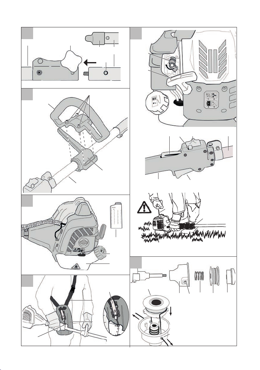
Montaggio
Montaggio del rivestimento
di protezione
Non utilizzare mai l’apparec-
chio nel caso in cui il rivestimento di protezione non sia
stato montato correttamente.
Sussiste pericolo d’infortuni.
1. Svitare le viti (28) del rivestimento di protezione (15) e rimuovere la cerniera.
2. Posizionare la copertura sul supporto del tubo (29).
3. Fissare il coperchio con viti (28).
Montaggio del tubo composto
da due parti
1. Rimuovere il cappuccio di prote-
zione (30) dal tubo inferiore (14).
2
. Allentare la vite di ssaggio (13)
sul tubo superiore (10).
3. Inserire i due tubi uno nell’altro
in modo tale che il pulsante di
sicurezza (31) si incastri nel foro
previsto nel tubo superiore (10).
4. Stringere bene nuovamente la
vite di ssaggio del tubo (13).
Prima dell’avvio dell’apparecchio,
assicurarsi che il tubo inferiore sia
1 3
Page 14

I T M T
ssato correttamente e si trovi nella
posizione giusta.re l’apparecchio.
5. Smontaggio:
Allentare la vite di ssaggio del tubo
(13). Premere il pulsante di sicurezza
(31) e staccare i tubi.
Montaggio impugnatura antivibrazione
1. Allentare le quattro viti (32) sul
manico antivibrazioni (11)
2. Inserire il manico antivibrazioni
(11) sul previsto sostegno gommato (33) sull’asta tubolare superiore (10).
3. Avvitare saldamente il manico antivibrazioni (11) con le 4 viti (32).
Messa in funzione
Avvertimento! Prima di met-
tere in funzione l’apparecchio
bisogna controllare che que-
sto sia in uno stato afdabile
e a prova di guasto. In caso
di dubbi, non avviare l’apparecchio!
Prestare attenzione soprattutto ai
seguenti punti:
• Controllo degli utensili da taglio rela-
tivamente a danneggiamenti e logoramento.
• Montaggio corretto della testa falcian-
te.
• Facile azionamento di tutti i pulsanti/
interruttori.
• Tenuta salda del cappuccio per la can-
dela d’accensione. Nel caso di cappuccio allentato possono crearsi delle
scintille e di conseguenza incendiare
la miscela carburante-aria.
1 4
• Assicurasi che le impugnature siano
pulite per poter permettere una guida
sicura dell’apparecchio.
• Tutti i dispositivi di sicurezza e di protezione devono essere assemblati a
norma di regola ed essere collocati al
proprio posto prima di avviare l’apparecchio.
La testa falciante deve poter stare
in funzione libera da ostacoli.
Prima di avviare l’apparecchio, accertarsi
che la testa falciante sia correttamente ssata
e che le parti mobili siano libere da ostacoli.
Avvertimento! In caso di qual-
siasi dubbio, richiedere aiuto
ad una persona specializzata
di un centro assistenza (Service-Center) autorizzato per
consentire il corretto funzionamento dell’apparecchio.
Rifornimento di carburante
Nel maneggiare il carburan-
te, provvedere sempre ad
una buona ventilazione. Non
fumare durante il processo di
rifornimento e tenere lontana
qualsiasi fonte di calore.
Non fare mai rifornimento
con il motore in funzione.
Aprire con cautela il tappo
del serbatoio in modo tale
che un’eventuale pressione
eccessiva possa diminuire.
Avviare l’apparecchio ad una
distanza di minimo 3 metri
dal luogo in cui si effettua il
rifornimento del carburante.
In caso di non osservanza si
possono vericare pericoli
d’incendio e di esplosione.
Page 15
M TI T
F G H I J
Impiegare soltanto la miscela di
carburante raccomandata nelle
istruzioni per l’uso. La miscela di
carburante è soggetta ad invecchiamento. Non utilizzare quindi
alcuna miscela di carburante che
sia più vecchia di 3 mesi. In caso
di inosservanza, il motore può
danneggiarsi e di conseguenza si
perderà il diritto alla garanzia.
Il volume di capienza del serbatoio
è di 650 ml.
Evitare il diretto contatto del-
la pelle con il carburante e
l’inalazione di vapori di benzina. Sussiste pericolo per la
salute!!
L’apparecchio è dotato
di un motore a due
tempi e viene quindi
azionato esclusivamente con una miscela
di benzina ed olio per motori a due tempi
nel rapporto di 50:1.
Tabella per la miscela
di carburante:
Benzina Olio per motori a due tempi
1,00 litri 20 ml
3,00 litri 60 ml
5,00 litri 100 ml
Processo di
miscelazione
• Utilizzare benzina senza piombo di
qualità con un numero di ottani di minimo 90.
• La prestazione ottimale viene raggiunta
con l’impiego di olio per motori a due
tempi appositamente sviluppato per
l’apparecchio. Se tale olio non è dispo-
50 parti di benzina
+ 1 parte di olio
nibile, utilizzare l’olio Super per motori
a due tempi a raffreddamento ad aria.
1. Mescolare la benzina e l’olio
sempre in un contenitore pulito
(25) previsto per contenere la
benzina.
2. Riempire prima con la metà
della benzina, versare tutta la
quantità d’olio e poi agitare il
contenitore. Aggiungere successivamente il resto della benzina
ed agitare di nuovo.
3. Svitare e togliere il tappo del
serbatoio (34) e versare nel
serbatoio di benzina la miscela
di carburante (7). Pulire i resti
di benzina intorno al tappo del
serbatoio e chiudere di nuovo il
tappo del serbatoio.
Posizionamento
della tracolla
Portare sempre una tracolla
quando si lavora con l‘apparecchio. Spegnere sempre
l‘apparecchio prima di staccare la tracolla. Pericolo di
infortuni.
La tracolla è provvista di un
dispositivo di rilascio veloce. Tirando la linguetta rossa (
l’apparecchio può venir staccato rapidamente dalla tracolla
in una situazione di pericolo.
1. Posizionare la tracolla (27) trasversalmente sul petto.
2. Regolare la lunghezza della
tracolla in modo tale che il moschettone si trova circa 10 cm
sotto l‘anca.
43)
1 5
Page 16

I T M T
A B C D E F G H I J
A B C D E F G H I J
3. Fissare il moschettone all‘‘occhiello della tracolla (19) sul
tubo dell‘apparecchio.
Appendere l‘apparecchio prima di
avviare il motore e ssarlo alla tracolla con il motore acceso.
Posizionare la protezione corpo
(26) sui anchi tra corpo e apparecchio.
Avvio del motore
Avviare il motore ad una di-
stanza minima di 3 metri dal
luogo in cui si esegue il rifornimento di carburante.
. Appoggiare l’apparecchio su una
base resistente e piana. Accertarsi
che l’utensile da taglio non tocchi
né oggetti né il suolo.
Avviamento a freddo:
1. Non dimenticare che il cappuccio di protezione sul taglialo
(
16) è rimosso.
2. Posizionare l’apparecchio su
una supercie solida e uniforme.
Prestare attenzione, che l’utensile
da taglio non tocchi né oggetti
né il terreno.
3. Portare la leva di comando dello
starter (3) in posizione della freccia.
4. Premere 6 volte la pompa del
carburante (Primer) (
5. Portare in posizione START
l’interruttore ON/OFF (20)..
6. Tenere l’apparecchio stringendo
saldamente con una mano l’asta
tubolare superiore (10). Con l’altra mano tirare rapidamente più
5).
volte la corda dell’impugnatura
di avviamento (4) no all’avvio
del motore.
L’apparecchio ora gira in folle.
Attenzione! Non tirare
troppo la corda di avviamento, potrebbe rompersi!
8. Lasciare riscaldare il motore per
circa 10 secondi.
7. Per falciare, mantenere premuta
la sicura della leva dell’acceleratore (22) ed azionare la
leva dell’acceleratore stessa (9).
All’azionamento della leva
dell’acceleratore, la leva
di comando dello starter
(3) si posiziona automaticamente nella posizione
avviamento a caldo.
8. Per lo spegnimento del motore,
portare nella posizione STOP
l’interruttore ON/OFF (20)..
Avviamento a caldo:
Durante l’avviamento a cal-
do con il pulsante di arresto
dell’acceleratore, il rocchetto
portalo si gira dopo l’avvio.
Tenere la distanza dal roc-
chetto portalo. Pericolo di
lesioni!
1. Lasciare la leva di comando
dello starter (3) nella propria
posizione.
2. Per la semiaccelerazione premere contemporaneamente la sicura della leva dell’acceleratore
(22), la leva dell’acceleratore (9)
e il pulsante di arresto dell’acceleratore (21) sull’impugnatura
(8). Quindi rilasciare la sicura
della leva dell’acceleratore (22)
0
1 6
Page 17

M TI T
e la leva dell’acceleratore stessa
(9). La semiaccelerazione è scattata in posizione.
3. Tenere l’apparecchio stringendo
saldamente con una mano l’asta
tubolare superiore (10). Con l’altra mano tirare rapidamente più
volte la corda dell’impugnatura
di avviamento (4) no all’avvio
del motore.
Attenzione! Non tirare
troppo la corda di avviamento, potrebbe rompersi!
L’apparecchio ora gira in semiaccelerazione.
4. Per lo spegnimento del motore,
portare nella posizione STOP
l’interruttore ON/OFF (20).
Se al secondo tentativo il motore
ancora non si avvia, provare ad accenderlo senza la leva di comando
in posizione avviamento a caldo.
Se anche questa procedura non
funziona, seguire le istruzioni del
capitolo „Ricerca guasti“.
Durante l’avviamento a caldo, la
falce passa in folle dopo il primo
azionamento della leva dell’acceleratore.
Utilizzo
Indicazioni d’uso
Lavorare in modo sicuro e
ponderato!
• Al momento di eseguire operazioni di
taglio, osservare le prescrizioni nazionali e comunali.
• Non eseguire operazioni di taglio du-
rante le usuali ore di riposo.
• Oggetti solidi come per esempio
sassi, pezzi di metallo o simile vanno
rimossi. Tali oggetti, infatti, potrebbero
essere scaraventati dall’apparecchio in
funzione e di conseguenza provocare
danni a persone e a cose.
• Durante le operazioni di taglio di siepi o cespugli alti, l’altezza dal suolo
dovrebbe essere di minimo 15 cm. In
questo modo non vengono messi in pericolo animali come per esempio i ricci.
• Mantenere l’apparecchio sempre con
entrambe le mani in modo stabile e
sicuro!
• Tagliare solo erba ed erbaccia! Prestare attenzione alle radici o ai ceppi,
poiché sussiste il rischio di inciampare.
0
• Lavorare con cautela per non mettere
in pericolo nessuno durante le operazioni di taglio. Lavorare in modo tranquillo e ponderato!
• Lavorare soltanto in condizioni visive e
di luminosità sufcientemente adeguate!
• Prestare attenzione alla testa falciante!
• Non eseguire mai operazioni di taglio
oltre l’altezza delle spalle!
• Non sostituire mai il lo di plastica con
un lo metallico/d’acciaio – Pericolo
di infortunio e di distruzione!
• Non lavorare su una scala!
• Lavorare soltanto su un suolo resistente
e stabile!
• Evitare una posizione del corpo anomala. Durante il suo utilizzo, tenere
saldamente l’utensile e mantenere sempre l’equilibrio.
• Cambiare a intervalli regolari la posizione delle operazioni di lavoro per
evitare l’affaticamento di un solo lato
del corpo.
• Durante il blocco del rocchetto porta-
lo spegnere subito dell’apparecchio,
tirare il cappuccio della candela e
rimuovere l’ostacolo.
1 7
Page 18

I T M T
Tosatura di erba
• Mantenere l’apparecchio su piccole
superci di erba ad un angolo di circa
30° e girare armonicamente intorno
a se stessi da destra a sinistra con un
movimento semicircolare.
• I migliori risultati si raggiungono quando l’erba ha un’altezza massima di 15
cm. Se l’erba è più alta, si consiglia di
effettuare più operazioni di tosatura.
• Per eseguire operazioni di taglio intorno ad alberi, pali od altri ostacoli, con
l’apparecchio girare intorno all’ostacolo lentamente e tagliare con la punta
dei li.
• Evitare il contatto con ostacoli solidi
(sassi, muri, staccionate, ecc.). Il lo
potrebbe consumarsi velocemente.
Impiegare il bordo del rivestimento di
protezione per tenere l’apparecchio
ad una giusta distanza.
Attenzione! Non appoggiare
la testa falciante sul suolo
mentre l’apparecchio è in
funzione!
Prolungamento del lo
L’apparecchio è dotato di un automatismo
a doppio lo con dispositivo a battuta
leggera, vale a dire i due li si allungano
quando la testa falciante tocca leggermen-
te il suolo.
1. Mantenere l’apparecchio che si trova
in funzione sopra una zona erbosa e
con la testa falciante toccare legger-
mente il suolo per un paio di volte. In
questo modo il lo si allunga.
2. Il coltello integrato nel rivestimento di
protezione (15) taglia il lo alla lunghezza desiderata.
Se le estremità del lo non si lasciano allungare:
• spegnere l’apparecchio,
• premere l’inserto della bobina no alla
battuta e tirare forte all’estremità del lo.
Se non sono più visibili le estremità
del lo:
• sostituire la bobina portalo (vedere
capitolo “Sostituzione della bobina”).
Attenzione! I resti del lo po-
trebbero essere scaraventati
dall’apparecchio in funzione
e provocare delle ferite.
Vibrazioni dell’apparecchio
Se l’apparecchio vibra, pulirlo nonché
rimuovere eventuali residui di erba dalla
testa falciante e dal rivestimento di protezione.
Manutenzione e cura
Eseguire i lavori di manuten-
zione e pulizia sempre con il
motore spendo e cappuccio
della candela estratto (
Fare eseguire tutte le operazioni che non vengono descritte in queste istruzioni soltanto dai servizi di assistenza
da noi autorizzati.
Usare solo parti originali e
mai li metallici. L’uso di pezzi non originali può provocare danni a persone e danni
irreparabili all’apparecchio
ed ha come conseguenza la
perdita immediata della garanzia.
2).
1 8
Page 19

M TI T
Pulitura dell’apparecchio
Dopo ogni operazione di taglio, pulire il
dispositivo di taglio e il rivestimento di protezione, eliminando erba e terra.
Proteggere l’apparecchio da
eventuali danneggiamenti!
• L’apparecchio non va né spruzzato con
acqua né messo in acqua.
• Non usare detersivi o solventi.
Sostituzione della bobina
1. Spegnere il motore.
2. Poggiare l’apparecchio a terra
e assicurarsi che non fuoriesca
carburante e che l’apparecchio
si trovi in una posizione stabile.
3. Tenere saldamente il cappuccio del
rocchetto e svitare la vite di ssag-
gio (35) in senso antiorario
. Rimuovere la capsula portabo-
bina (17) con la bobina lo (18).
4. Inserire la nuova bobina (18)
nella capsula (17) e inlare le
due estremità del lo nell’occhiello uscita lo (36). Prestare atten-
zione che la molla (37) si trovi
nella posizione corretta.
5. Premere la bobina lo (18) nella
capsula portabobina (17) e strin-
gere la vite di ssaggio (35) in
senso orario
6. Tirare entrambe le estremità del
lo per allentare i li dalle scanalature.
7. Regolare il lo a ca. 13cm, per
ridurre il carico del motore nella
fase di avvio e riscaldamento.
I ricambi ordinabili si trovano nel
capitolo “Ricambi/accessori”
.
Pulizia del ltro dell’aria
Non usare mai l’apparecchio da ta-
glio senza ltro dell’aria. Altrimenti
possono entrare polvere e sporcizia
nel motore e possono provocare
danni all’apparecchio. Tenere pulito
il ltro dell’aria.
1. Spegnere il motore.
2. Allentare la vite (38) sul co-
perchio del ltro dell’aria (6) e
rimuovere il coperchio dall’allog-
giamento (6) del ltro dell’aria
(39)
3. Rimuovere il ltro dell’aria (39)
dall’alloggiamento ltro dell’aria
(39).
4. Pulire il ltro (40) dell’aria con
sapone e acqua e lasciarlo
asciugare all’aria.
Non utilizzare mai la ben-
zina per pulire!
5. Rimontare il ltro dell’aria (40) e
il coperchio del ltro dell’aria (6)
nella sequenza inversa.
Sostituire il ltro dell’aria (40) quan-
do questo è logorato, danneggiato
o molto sporco (vedere “Ricambi/
accessori”).
Sostituzione/regolazione
della candela di accensione
Candele di accensione usurate op-
pure una distanza interelettrodica
troppo grande conducono ad una
riduzione di potenza del motore.
1. Spegnere il motore.
2. Staccare il cavo di accensione
(2) dalla candela di accensione
(41).
1 9
Page 20

I T M T
3. Svitare la candela di accensione
(41) in senso antiorario con
la chiave di manutenzione fornita (vedi
4. Controllare la distanza interelettrodica con l’ausilio di uno spessimetro (disponibile in negozi
specializzati).
La distanza interelettrodica
deve essere 0,6-0,7 mm.
5. Eventualmente regolare la distanza piegando delicatamente l’elettrodo di massa della candela
di accensione (41).
6. Pulire la candela di accensione
(41) con una spazzola metallica.
7. Inserire la candela di accensione
(41) pulita e regolata oppure sostituire la candela di accensione
danneggiata con una candela di
accensione nuova (p. es. candela
di accensione “TORCH L8RTC”).
8. Inserire di nuovo il cavo di accensione (2).
I ricambi ordinabili si trovano nel
capitolo “Ricambi/accessori”
23).
Aflare dispositivo di taglio
del lo
Non utilizzare, in nessun
caso, l’apparecchio senza
dispositivo di taglio o con
dispositivo di taglio difettoso.
Sussiste pericolo d’infortuni.
Nel caso in cui sia danneggiata la lama del dispositivo
di taglio, rivolgersi necessariamente al nostro servizio
assistenza (Service-Center).
1. Spegnere il motore.
2. Svitare il dispositivo di taglio del
lo (16) dal rivestimento di protezione (15).
3. Fissare il dispositivo di taglio del
lo (16) in una morsa e aflare
il coltello con una lima piatta.
Aflare con cautela e sempre in
una sola direzione.
4. Riavvitare il dispositivo taglialo
(16) al rivestimento di protezione (15).
I ricambi ordinabili si trovano nel
capitolo “Ricambi/accessori”
Sostituzione ltro carburante
Non usare mai l’apparecchio
senza il ltro del carburante.
Sostituire regolarmente il l-
tro del carburante.
1. Svitare il tappo del serbatoio
(34).
2. Svuotare il contenuto del serbatoio del carburante (7) in un
apposito contenitore.
3. Con un gancio estrarre il ltro
del carburante (42) dal serbatoio e rimuoverla con un movimento rotatorio.
4. Sostituire il ltro del carburante
e riporre nuovamente la ventosa
staccata nel serbatoio.
5. Richiudere il serbatoio del carburante (7) con il tappo del serbatoio (34).
I ricambi ordinabili si trovano nel
capitolo “Ricambi/accessori”
Indossare guanti di protezione per
evitare ferite da taglio.
2 0
Page 21

M TI T
M
Avvolgere il rocchetto
portalo
In alternativa a un nuovo rocchetto por-
talo nei negozi specializzati è possibile
reperire un lo di nylon dallo spessore di
2 mm, rispettivamente 1,8 mm di spessore,
5 m di lunghezza che può essere avvolto
sul rocchetto portalo.
1. Piegare il lo nel centro e ripiegare la metà del lo nell’intacca-
tura (45) del rocchetto (18). Avvolgere entrambe le estremità in
direzione della freccia
, che è presente sul lato inferiore
del rocchetto.
2. Inne inlare l’estremità del lo
in una delle scanalature (46) sul
rocchetto (18).
Per lo spessore del lo di 2 mm
scegliere le scanalature contrassegnate con il numero 2, per lo
spessore 1,8 mm scegliere le
scanalature contrassegnate con
il numero 1,8.
Tendere i li e prestare attenzione
afnché i li siano paralleli in
entrambi i canaletti. Inoltre non si
deve inserire sul rocchetto più di
2,5 mm di lo per canaletto, altrimenti non funziona automaticamen-
te in modo corretto.
Regolazione del carburatore
Rimuovere le cause di blocco
Spegnere l’apparecchio ed
estrarre il cappuccio della
candela prima di lavorare
all’unità di taglio.
Indossare i guanti protettivi, in
modo da evitare di ferirsi tagliandosi.
Vericare il raccordo
Posizionare l’apparecchio su una
supercie solida e uniforme. Prestare attenzione, che l’utensile da
taglio non tocchi né oggetti né il
terreno.
Vericare prima di ogni utilizzo la funzionalità del raccordo in folle.
Avviare l’apparecchio (vedere “Avviare
il motore”) e vericare tramite verica di
sicurezza con distanza di sicurezza sufciente, se il rocchetto portalo non si ruota
in folle.
Intervalli di manutenzione
Eseguire regolarmente i lavori di manutenzione riportati nella tabella. Una manutenzione a intervalli regolari allunga la
durata di vita dell’apparecchio. Inoltre, si
raggiungono risultati di taglio ottimali e si
evitano incidenti.
Il carburatore è stato preimpostato in fabbrica a potenza ottimale. Se dovessero
essere necessarie ulteriori regolazioni, fare
eseguire tali operazioni di regolazione
presso un’ofcina specializzata.
2 1
Page 22

I T M T
Tabella intervalli di manutenzione:
Pezzo dell’apparecchio Operazione
Viti, dadi, perni Controllare, serrare
Filtro dell’aria Pulire o sostituire
Filtro del carburante Sostituire
Candela di accensione
Pompe del carburante
Apparecchio completo
Manico di guida Controllare se funziona
Testa falciante
Raccordo
Pulire / regolare /
sostituire
Controllare, se necessario
sostituire
Controllare, se necessario
pulire
Controllare se montata
correttamente
Vericare di il rocchetto portalo non si ruota in folle
Magazzinaggio
Indicazioni generali relative
al magazzinaggio
Magazzinaggio in intervalli
di non utilizzo
Prima di
ogni uso
Ore di utilizzo
10 20
• Pulire accuratamente l’apparecchio e
gli accessori in modo tale da prevenire
la formazione di muffa.
• Conservare l’apparecchio in un luogo
asciutto e senza polvere, lontano dalla
portata dei bambini.
• Non avvolgere l’apparecchio in sacchi
di plastica perché altrimenti ciò potreb-
be condurre alla formazione di umidità
e di muffa.
• Non appoggiare l’apparecchio dalla
parte del rivestimento di protezione,
preferibilmente appenderlo dal manico
superiore.
2 2
L’inosservanza delle indicazioni
relative al magazzinaggio può
causare, mediante residui di carburante nel carburatore, problemi di
avvio o danni permanenti.
1. Svuotare il serbatoio del carburante
(7) in un luogo ben ventilato.
2. Avviare il motore e lasciarlo girare a
vuoto (in folle) nché il motore non si
ferma e il carburatore sia del tutto pri-
vo di carburante.
3. Lasciare raffreddare il motore (circa
5minuti).
Page 23

M TI T
J
A B C D E F G H I J
J
A B C D E F G H I J
A B C D E F G H I J
In caso di intervalli di non impiego
di oltre 3 mesi:
4. Allentare la candela di accensione
(
41) con una chiave a tubo per
candele (
“Sostituzione / regolazione della candela di accensione”).
5. Versare un cucchiaino di olio puro per
motori a due tempi nella camera di
combustione e tirare più volte lentamente la corda d’avviamento per consentire all’olio di distribuirsi all’interno
del motore.
6. Inserire di nuovo le candele di accensione (
23) (vedere il capitolo
41).
Trasporto
• Durante il trasporto l’apparecchio deve
essere spento e il cappuccio della candela (
Non trasportare l’apparecchio in folle.
• Portare l’apparecchio con la mani-
glia multifunzione e antivibrazioni (
trasporto il contatto con componenti
pericolosi (per esempio motore caldo,
unità di taglio).
• Rispettare durante il trasporto una distanza di sicurezza da terze persone.
• Non trasportare l’apparecchio a corpo
morto, per impedire la fuoriuscita del
carburante.
2) rimosso.
8+11) così da evitare durante il
Smaltimento/Tutela
dell’ambiente
Non versare l’olio usato e resti di benzina
nella canalizzazione o nello scarico. Smaltire l’olio usato e i resti di benzina in con-
formità alle norme di tutela dell’ambiente,
consegnandoli presso un centro di raccolta
e smaltimento.
Effettuare lo smaltimento dell’apparecchio,
degli accessori e della confezione nel
rispetto dell’ambiente presso un punto di
raccolta per riciclaggio.
Le apparecchiature non si devono smaltire
insieme ai riuti domestici.
Consegnare l’apparecchio presso un centro
di raccolte e ricupero. Le parti plastiche e
di metallo usate potranno essere selezionate e avviate al ricupero.
Lo smaltimento degli apparecchio difettosi
consegnati viene effettuato gratuitamente.
Chiedere informazioni a riguardo al nostro
centro assistenza clienti.
2 3
Page 24

I T M T
Ricambi/accessori
È possibile ordinare pezzi di ricambio e accessori all’indirizzo
www.grizzly-service.eu
Se non si dispone di una connessione Internet, contattare telefonicamente il centro di
assistenza (vedere “Service-Center” a pag. 26). Tenere a portata di mano i numeri d’ordine riportati in basso.
Position Position Denominazione Numeri
Istruzioni Disegno d’ordine
per l’uso esploso
15 37-40,43,44 Set copertura di protezione 13602025
18 52,54 Rocchetto portalo 13602029
17 51-55 Testa del rocchetto 13602027
37 53 Molla del rocchetto portalo 13602028
16 41,42 Taglialo 13602026
14 33-36,47-50 del tubo inferiore completamente 13602024
27-32 Manicotto di collegamento 13602023
11+12 23,25,26 Maniglia+protezione gambe 13602022
27 13 Tracolla+protezione anchi 13602021
42 80 Filtro della benzina 13602043
77-79 Tubi della benzina 13602042
34 69-74 Tappo del serbatoio 13602040
40 22 Filtro dell’aria 13602034
38 24 Vite ltro dell’aria 13602035
41 28 Candela 13602036
In alternativa può essere utilizzato come ricambio il rocchetto portalo AutoCut C5-2
della Stihl.
Si può, in ogni caso, reperire nei negozi specializzati un lo di nylon di 2 mm, rispettivamente 1,8 mm di spessore, 5 m di lunghezza che può essere avvolto sul rocchetto
portalo (vedere capitolo “Avvolgere il rocchetto portalo”).
2 4
Page 25

M TI T
Garanzia
Gentile cliente, Su questo apparecchio Le
viene concessa una garanzia di 3 anni a
partire dalla data di acquisto.
In caso di difetti di questo prodotto può
avanzare diritti legali nei confronti del
venditore del prodotto. Tali diritti legali non
vengono limitati dalla nostra garanzia qui
di seguito rappresentata.
Condizioni di garanzia
Il termine di garanzia inizia con la data di
acquisto. La preghiamo di conservare in
un luogo sicuro lo scontrino scale originale. Questo documento viene richiesto come
prova d’acquisto.
Qualora subentrasse un difetto di materiale
o di fabbricazione entro tre anni a partire
dalla data di acquisto di questo prodotto,
il prodotto verrà riparato o sostituito – a
nostra discrezione - gratuitamente da noi.
Questa prestazione di garanzia presuppone che venga presentato entro il termine di
tre anni l’apparecchio difettoso e la prova
d’acquisto (scontrino scale) e descritto
brevemente per iscritto in che cosa consiste
il difetto e quando si è vericato.
Se il difetto è coperto dalla nostra garan-
zia, riceverà il prodotto riparato oppure
un prodotto nuovo. Con la riparazione o
la sostituzione del prodotto non inizia un
nuovo periodo di garanzia.
Tempo di garanzia e diritti legali
per vizi della cosa
Il periodo di garanzia non viene prolungato. Questo vale anche per parti sostituite
e riparate. Difetti e vizi presenti già al
momento dell’acquisto devono essere segnalati immediatamente dopo la rimozione
dall’imballaggio. Riparazioni che accorrono dopo il periodo di garanzia sono a
pagamento.
Volume di garanzia
L’apparecchio è stato prodotto accuratamente secondo severe direttive di qualità
e controllato con coscienza prima della
consegna.
La prestazione di garanzia vale per difetti
di materiale o di fabbricazione. Questa
garanzia non si estende ai componenti
del prodotto che sono soggetti a normale
usura e che quindi possono essere visti
come parti di usura (per esempio rocchetto
portalo, lo da taglio, taglialo, ltro dell‘aria e candela) oppure per danneggia-
menti delle parti fragili (p. es. interruttori).
Questa garanzia decade se il prodotto è
stato danneggiato, non usato correttamente o non manutenuto. Per un uso corretto
del prodotto devono essere osservate tutte
le indicazioni riportate nelle istruzioni per
l’uso. Destinazioni d’uso e azioni sconsigliate nelle istruzioni d’uso o dalle quali
si viene avvertiti, sono tassativamente da
evitare.
Il prodotto è destinato solo per i privati e
non per uso commerciale. In caso di uso
improprio, esercizio della forza e interventi non effettuati dalla nostra liale di
assistenza tecnica autorizzata, decade la
garanzia.
Svolgimento in caso di garanzia
Per garantire una rapida elaborazione della Sua pratica, La preghiamo di seguire le
seguenti indicazioni:
• Per tutte le richieste tenere a portata
di mano lo scontrino scale e il codice
di identicazione (IAN 280454) come
prova d’acquisto.
• I codici articolo sono riportati sulla targhetta del tipo.
• Nel caso in cui si dovessero vericare
difetti funzionali o altri vizi, La preghia-
mo di contattare telefonicamente o per
2 5
Page 26

I T M T
e-mail. Riceverà ulteriori informazioni
sullo svolgimento del Suo reclamo.
• Un prodotto rilevato come difettoso
può essere inviato con porto franco
all’indirizzo di assistenza comunicato,
previa consultazione del nostro servizio di assistenza tecnica, allegando
la prova d‘acquisto (scontrini scali)
e l’indicazione, in che cosa consiste
il difetto e quando si è vericato. Per
evitare problemi di accettazione e costi
aggiuntivi, usare tassativamente solo
l’indirizzo che Le è stato comunicato.
Assicurarsi che la spedizione non avvenga in porto assegnato, con merce
ingombrante, corriere espresso o altro
carico speciale. Spedire l’apparecchio
inclusi tutti gli accessori forniti insieme
al momento dell’acquisto e garantire
un imballaggio di trasporto sufcientemente sicuro.
Servizio di riparazione
Riparazioni non soggette alla garanzia possono essere effettuate dietro fattura
dalla nostra liale di assistenza tecnica
previo preventivo gratuito da parte della
stessa.
Possiamo lavorare solo apparecchi che
vengono spediti sufcientemente imballati
e affrancati.
Attenzione: Spedire l’apparecchio alla
nostra liale in condizioni pulite e con l’indicazione del difetto.
Apparecchi spediti in porto assegnato con merce ingombrante, corriere espresso
o altro carico speciale - non vengono
accettati.
Lo smaltimento degli apparecchi difettosi
spediti viene effettuato da noi gratuitamen-
te.
Service-Center
Assistenza Italia
I T
Tel.: 02 36003201
E-Mail: grizzly@lidl.it
IAN 280454
M T
Assistenza Malta
Tel.: 80062230
E-Mail: grizzly@lidl.com.mt
IAN 280454
Importatore
Non dimenticare che il seguente indirizzo
non è un indirizzo di assistenza tecnica.
Contattare prima di tutto il centro di assistenza tecnica sopra nominato.
Grizzly Tools GmbH & Co. KG
Stockstädter Straße 20
63762 Großostheim
Germania
www.grizzly-service.eu
2 6
Page 27

Ricerca guasti
Problema Causa possibile Rimozione di errore
Serbatoio vuoto Fare il pieno di carburante
Osservare le indicazioni, all’inter-
Motore non si
avvia
Motore va troppo
veloce quando è
in folle
Motore non va a
massima potenza
Formazione di
gas di scarico /
fumo eccessivo
Successione errata delle fasi di avvia-
mento
Motore “ingolfato”
Candele di accensione fuligginose,
distanza interelettrodica errata
Allacciamento delle candele e/o
cavo d’accensione danneggiati
Carburatore e/o ugelli del carburato-
re sporchi, preparazione errata della
miscela per il carburatore
Filtro del carburante intasato
Motore freddo
Candele di accensione fuligginose,
distanza interelettrodica errata
Filtro dell’aria sporco Pulire o sostituire il ltro dell’aria
Carburatore e/o ugelli del carburatore sporchi, preparazione errata della
miscela per il carburatore
Miscela di carburante errata
Anello di guarnizione nel basamento
permeabile
Cilindro e/o anello di tenuta del
pistone usurata
Accensione errata
Preparazione errata della miscela per
il carburatore
Miscela di carburante errata
no di queste istruzioni per l’uso,
relative all’avviamento dell’apparecchio
Togliere gas, avviare più volte,
se necessario smontare, pulire
e fare asciugare la candela di
accensione
Pulire, regolare o sostituire le
candele di accensione
Sostituire
Fare pulire e regolare il carburato-
re da un’ofcina specializzata
Sostituire o pulire il ltro del car-
burante
Farlo riscaldare lentamente,
eventualmente chiudere un po’ la
valvola dell’aria
Pulire, regolare o sostituire le
candele di accensione
Fare pulire e regolare il carburato-
re da un’ofcina specializzata
Fare rifornimento secondo le istru-
zioni per l’uso
Far rimuovere l’errore da un’ofcina specializzata
Fare regolare il carburatore da
un’ofcina specializzata
Fare rifornimento secondo le istru-
zioni per l’uso
M TI T
2 7
Page 28

P T
Índice
Introdução .................................28
Âmbito de aplicação .................29
Descrição Geral ..........................29
Material que acompanha o fornecimen-
to ................................................29
Funcionamento ..............................29
Vista geral ....................................29
Funções de segurança ....................30
Dados Técnicos ...........................30
Medidas de segurança ...............31
Símbolos colocados
no manual ....................................31
Símbolos grácos colocados no aparel-
ho ...............................................31
Medidas de segurança gerais .........32
Regras de segurança
adicionais ....................................35
Instruções de montagem ............36
Montar a capa protetora ................36
Montar o tubo de duas peças .........36
Montar o punho antivibrações .......36
Colocação em funcionamento .....37
Abastecer combustível ....................37
Colocar a alça para ombro ............38
Ligar o motor ................................38
Operação ...................................40
Instruções de trabalho ....................40
Cortar relva ..................................40
Prolongar o o ..............................40
Se o aparelho vibrar ......................41
Manutenção e conservação ........41
Limpar o aparelho .........................41
Substituição da bobina ..................41
Limpar o ltro de ar .......................42
Substituir/ajustar velas de ignição ...42
Aar o cortador de o ..................43
Substituir o ltro do combustível .....43
Enrolar a bobina de o .................43
Ajustar o carburador ......................44
Remover bloqueios ........................44
Vericar a embraiagem ..................44
Intervalos de manutenção ...............44
Estoque ......................................45
Indicações gerais sobre o armazena-
mento ..........................................45
Armazenamento durante os intervalos
de funcionamento ..........................45
Transporte .................................45
Reciclagem/Protecção
ambiental ..................................45
Peças sobressalentes/
Acessórios ..................................46
Garantia ....................................47
Serviço de reparação .................48
Service-Center ............................48
Localização de erros ..................49
Tradução do original da Declaração
de conformidade CE ...................97
Vista em corte .................. 100/101
Introdução
Parabéns pela compra do seu novo aparelho. Com a sua compra, decidiu-se por um
produto de alta qualidade.
Este aparelho foi testado durante a produção em relação à qualidade e submetido
a uma inspeção nal. A funcionalidade do
seu aparelho está desta forma garantida.
O manual de instruções é uma parte
integrante deste artigo. Ele contém
indicações importantes referentes à
segurança, utilização e eliminação.
Familiarize-se com todas as indicações de utilização e de segurança
do artigo. Utilize este artigo da forma que é descrita e apenas para as
nalidades indicadas.
Guarde bem o manual e, se transmi-
tir o artigo a terceiros, entregue também todos os respetivos documentos.
2 8
Page 29

P T
A
Âmbito de aplicação
O Motorsense a gasolina é adequado
para o corte de relva em jardins, ao longo
de bordas de canteiros e em torno de árvores ou estacas de cercas.
Qualquer outro uso contrário àquele que foi
autorizado pode levar a danos no aparelho e
constituir um perigo sério para o seu utilizador.
O aparelho não se destina ao corte de arbustos, árvores pequenas ou plantas semelhantes.
Este aparelho destina-se a ser utilizado por
adultos. Jovens maiores de 16 anos poderão
utilizar o aparelho apenas sob vigilância.
O fabricante não se responsabiliza pelos
danos causados pela utilização abusiva ou
pelo uso indevido do aparelho.
Descrição Geral
As ilustrações podem ser encontra-
das no verso e reverso da página
destacável.
Material que acompanha o
fornecimento
Funcionamento
O Motorsense a gasolina FBS 25 A1,
guiado à mão e portátil, tem como acionamento um motor de combustão, que está
continuamente em funcionamento durante
o trabalho. A transferência de força é
realizada por meio de um disco de em-
braiagem, o qual transmite a potência do
motor ao dispositivo de corte através de
uma embraiagem centrífuga.
Enquanto dispositivo de corte, o aparelho
possui uma bobina de o duplo, a qual
está equipada com um dispositivo automático de toque. Durante o processo de
corte, dois os de material sintético rodam
em torno de um eixo, de forma vertical em
relação ao nível de corte.
Para proteger o utilizador, o aparelho é
fornecido com um dispositivo de proteção,
que cobre o dispositivo de corte.
Para car a conhecer a função e o manejo
das peças consulte, por favor, as de-
scrições técnicas seguintes.
Vista geral
Ao desembalar o aparelho, verique se o
fornecimento é completo. Eliminar a emba-
lagem de maneira apropriada.
• Carcaça do motor com tubo do eixo
superior e punho multifunções
• Tubo do eixo inferior com bobina de
o montada
• Capa protetora
• Punho antivibrações com proteção de
pernas
• Alça para ombro com proteção corporal
• Chave de manutenção
• 100 ml de óleo de 2 tempos
• Recipiente de mistura de 500 ml de
óleo/gasolina
• Manual de Instruções
1 Carcaça do motor
2 Ficha da vela de ignição
3 Alavanca
do estrangulador de ar
4 Pega de arranque
com cabo de arranque
5 Bomba do combustível (Primer)
6 Tampa do ltro de ar
7 Depósito do combustível
8 Punho multifunções
9 Alavanca de aceleração
10 Tubo do eixo superior
11 Punho antivibrações
12 Proteção de pernas
13 Parafuso de xação do tubo
14 Tubo do eixo inferior
15 Capa protetora
2 9
Page 30

P T
B
C
D
E
F
H
I
J
L
M
16 Cortador de o
17 Cápsula da bobina
18 Bobina de o (não visível)
19 Olhal de suporte
para a alça para ombro
20 Interruptor de ligar/desligar
21 Botão de paragem
de aceleração
22 Bloqueio da alavanca
de aceleração
23 Chave de manutenção
24 100 ml de óleo de 2 tempos
25 Recipiente de mistura
de 500 ml de óleo/gasolina
26 Proteção corporal
27 Alça para ombro
44 Bolsa para ferramentas
28 2 parafusos da capa protetora
29 Suporte do eixo
30 Capa protetora de transporte
31 Botão de segurança
do tubo do eixo
32 4 parafusos do punho
antivibrações
33 Suporte do punho antivibrações
34 Tampa do depósito
43 Lingueta do dispositivo
de desbloqueio rápido
35 Parafuso de xação
da bobina de o
36 Olhal de saída do o
37 Mola da bobina de o
38 Parafuso da tampa
do ltro de ar
39 Carcaça do ltro de ar
40 Filtro de ar
41 Vela de ignição
42 Filtro do combustível
45 Entalhe da bobina de o
46 Ranhura da bobina de o
Funções de segurança
22 Bloqueio da alavanca de
aceleração
evita uma aceleração acidental
do motor. A alavanca de aceleração só pode ser acionada
se o bloqueio da alavanca de
aceleração estiver premido.
20 Interruptor de ligar/
desligar
Com o interruptor de ligar/desligar o motor é desligado. Este
deve encontrar-se na posição
para voltar a ligar o motor.
15 Capa protetora
protege a pessoa do contacto
involuntário com a ferramenta
de corte e dos objetos estranhos
ejetados.
Dados Técnicos
RoÇadeira a gasolina ..............FBS 25 A1
Motor .................... Motor de dois tempos
........................................de um cilindro
Mistura de combustível ....................50:1
Cilindrada do motor ..................25,4 cm
Potência máx. do motor 0,75 kW (1,1 PS)
Rotações do motor em ralenti ..2800 min
Rotações máx. do fuso ............ 8500 min
Volume do depósito .............. 650 ml/cm³
Peso (sem conteúdo do depósito) ... 5,9 kg
Fio
Círculo de corte ......................380 mm
Espessura do o .........................2 mm
Comprimento do o ...................... 5 m
-1
-1
3
3 0
Page 31

P T
Nível de pressão acústica
(L
) ...................98,2 dB(A), KpA= 3 dB
pA
Nível de potência acústica (L
WA
)
garantido ............................ 110 dB(A)
medido ........... 108,2 dB(A); K
Vibração (a
) ..... 12,93 m/s2; K=1,5 m/s
h
= 3 dB
WA
Os valores de ruído e de vibração foram
apurados de acordo com as normas e disposições mencionadas na declaração de
conformidade.
Medidas de segurança
Para poder operar o aparelho em
segurança, todas as instruções e
informações sobre a segurança,
composição e operação no manual
de instruções devem ser seguidas
com exatidão. Todas as pessoas
encarregues da operação ou da
manutenção deste aparelho devem
conhecer o manual de instruções
e estar informadas sobre possíveis
perigos.
Símbolos colocados
no manual
Símbolos grácos colocados
no aparelho
Pode encontrar indicações simbólicas no
seu aparelho. Estas indicações transmitem
2
informações importantes sobre o produto
ou indicações sobre a utilização.
• Atenção: São necessárias medidas de
segurança especiais no manuseamento
do aparelho!
• Ler e compreender todo o manual de
instruções antes da utilização. A inobservância das indicações de operação
pode ter como consequência perigo
de morte!
Antes de utilizar, ler com
atenção!
Use óculos de protecção.
Utilize um capacete.
Use protector de ouvidos.
Sinal de perigo com indi-
cações sobre a prevenção de
danos físicos ou materiais.
Símbolos de ordens com informações
sobre a prevenção de danos.
Avisos de instrução, com infor-
mações sobre o melhor manuseamento com o aparelho.
Usar luvas de protecção.
Perigo de corte!
Utilize luvas de proteção com
palmas sólidas.
Certique-se de que a cabeça
de corte não toca com corpos
estranhos durante o arranque e
durante os trabalhos.
Mantenha uma distância de segurança de, pelo menos, 15
metros em relação a terceiros.
3 1
Page 32

P T
Perigo de ferimentos devido a
peças ejectadas! Manter as pes-
soas espectadoras afastadas da
área de perigo.
Atenção! O combustível e os
vapores de combustível são in-
amáveis. Perigo de incêndio e
de explosão!
Atenção a superfícies quentes, perigo de queimaduras!
Atenção! Trabalhe apenas com
uma bobina de o.
Não utilize uma lâmina de corte metálica ou uma lâmina de
serra. Perigo de ferimentos!
Indicação do nível de potência
acústica L
Utilizar APENAS mistura
de combustível
em dB.
WA
Proporção de mistura
de 50:1, utilizar
APENAS mistura de
combustível
Bomba do combustível (Primer)
Medidas de segurança gerais
Manter afastado do alcance de crianças,
bem como de pessoas doentes ou frágeis.
Observar atentamente as crianças caso se
encontrem nas proximidades de máquinas.
Tenha em atenção as normas de prevenção de acidentes regionais e locais,
aplicáveis ao seu caso. O mesmo aplica-se
a todas as disposições de segurança no
trabalho e saúde no local de trabalho.
O fabricante não assume qualquer responsabilidade caso as suas máquinas sejam modi-
cadas sem permissão e caso resultem danos
ou ferimentos dessas mesmas modicações.
Aviso! Durante a utilização
de máquinas devem ser
sempre tomadas medidas
de precaução básicas. Tenha
também em atenção todas as
sugestões e indicações nas
indicações de segurança adicionais.
3 2
Círculo de corte
Processo de arranque
1. Tenha atenção às condições ambientais com as quais trabalha.
O aparelho motorizado produz gases
de escape tóxicos assim que o motor arrancar. Estes gases podem ser
inodoros e invisíveis. Por isso, nunca
efetue trabalhos com o aparelho em
espaços fechados ou com pouca
ventilação. Certique-se de que existe
uma iluminação suciente durante os
trabalhos. Em caso de chuva, neve ou
gelo, tenha atenção à estabilidade em
declives e terrenos desnivelados.
Page 33

P T
2. Não permita que estranhos
utilizem o aparelho. Visitantes
e espectadores, sobretudo crianças,
pessoas doentes e frágeis, devem ser
mantidos afastados do local de trabal-
ho. Evite que outras pessoas entrem
em contacto com as ferramentas.
Transmita o aparelho apenas a pes-
soas que estejam familiarizadas com o
aparelho e com o seu manuseamento.
3. Certique-se de que as ferramentas são armazenadas com segurança. As ferramentas que não são
utilizadas devem ser armazenadas ou
fechadas sem possibilidade de acesso
num local seco e, de preferência, elevado.
4. Utilize sempre a ferramenta certa para cada trabalho. Não utili-
ze, por exemplo, ferramentas pequenas
ou acessórios para trabalhos que de-
vem ser realizados com ferramentas de
maior dimensão. Utilize as ferramentas
exclusivamente para a nalidade para
a qual foram construídas.
5. Utilize vestuário adequado. O
vestuário deve ser adequado à nalidade e não deve dicultar os trabal-
hos. Utilize vestuário com proteções
contra corte.
6. Utilize equipamento de proteção
individual. Utilize luvas de proteção
com palmas de aço e aderentes.
Utilize um capacete de proteção caso
exista o perigo de queda de objetos
durante o trabalho.
7. Use óculos de proteção. Objetos
podem ser projetados na sua direção. Po-
dem ocorrer ferimentos oculares graves.
8. Utilize proteção auditiva. Utilize
proteção individual contra ruído, por
exemplo, tampões de proteção auditiva.
9. Proteção das mãos. Utilize luvas
resistentes - as luvas de couro proporcionam uma boa proteção.
10. Operação do aparelho. Nunca
trabalhe sem a proteção na ferramenta
de corte. Perigo de ferimentos devido
a objetos projetados.
11. Retire a chave de caixa, etc.
Todas as chaves, etc., devem ser removidas antes de ligar o aparelho.
12. Permaneça sempre atento.
Tenha atenção àquilo que faz.
Utilize o seu bom senso. Não utilize
ferramentas motorizadas se estiver
cansado. O aparelho não pode ser
operado sob a inuência de álcool,
drogas ou medicamentos que afetem a
capacidade de reação.
13. Enchimento com combustível.
• Cumpra sempre a disposição de
proteção contra incêndios em vigor
e as respetivas disposições nacionais/regionais sobre a prevenção
de incêndios.
• O combustível e os vapores de
combustível são muito inamáveis.
Não encha combustível enquanto o
motor estiver em funcionamento ou
ainda quente. Certique-se de que
existe uma boa ventilação durante
o abastecimento. É proibido fumar
ou criar chamas desprotegidas.
• O motor deve ser sempre desligado
antes do enchimento. Abra o fecho do
depósito sempre de forma cuidadosa,
para que a sobrepressão existente
diminua lentamente e não ocorra a
projeção de combustível. Durante o
trabalho com o aparelho, a carcaça
atinge temperaturas elevadas. Por
isso, deixe o aparelho arrefecer
antes do abastecimento. Caso contrário, o combustível pode incendiar
e provocar queimaduras graves.
• Antes do enchimento com combustí-
vel, certique-se de que não é abastecida uma quantidade demasiado
3 3
Page 34

P T
elevada. Caso transborde líquido,
este deve ser removido de imediato
e o aparelho deve ser limpo.
• Após o enchimento, certique-se
de que a união roscada de fecho
está bem xa para evitar que se
solte durante o trabalho devido às
vibrações que se formam.
• Tenha atenção a eventuais fugas.
Em caso de fuga de combustível,
não ligue o motor. Perigo de morte
devido a queimaduras!
14. Duração de utilização e pausas. Uma utilização prolongada do
aparelho motorizado pode provocar
distúrbios na circulação sanguínea
das mãos devido às vibrações. No
entanto, pode prolongar a duração da
utilização, usando luvas adequadas
ou realizando intervalos regulares.
Tenha em atenção, que a tendência
pessoal de má circulação, as baixas
temperaturas exteriores ou as elevadas
forças de preensão durante os trabalhos reduzem a duração de utilização.
15. Tenha atenção a peças danicadas. Verique o aparelho antes da
colocação em funcionamento e após
impactos fortes quanto a sinais de
danos e desgaste. Existem peças estão
danicadas? No caso de danos leves,
questione seriamente se a ferramenta
continua a funcionar sem problemas e
de forma segura. Certique-se de que
as peças móveis estão corretamente alinhadas e ajustadas. As peças
encaixam bem umas nas outras? As
peças estão danicadas? Está tudo
instalado corretamente? Todos os outros
requisitos de funcionamento correto
estão cumpridos? Os dispositivos de
proteção danicados, etc. devem ser
reparados ou substituídos corretamente
por pessoas autorizadas, caso não
exista outra indicação no manual de
instruções. Os interruptores danicados
devem ser substituídos por uma entidade autorizada. No caso de reparações
necessárias, contacte um serviço de
apoio ao cliente autorizado por nós.
16. Desligue sempre o motor antes de
realizar ajustes ou trabalhos de manutenção. Isto aplica-se sobretudo em
trabalhos na bobina de o.
17. Utilize apenas peças autorizadas. Utilize apenas peças idênticas
em caso de manutenção e reparação.
Contacte o centro de assistência da
Grizzly para peças de substituição.
Aviso! A utilização de outras
cabeças de corte, bem como
acessórios e componentes,
que não foram expressamente recomendadas, pode ter
como consequência perigos
para pessoas e objetos.
A ferramenta só pode ser
utilizada para a sua nalidade de utilização prevista.
Qualquer outra nalidade
que não a prevista é considerada utilização incorreta.
O utilizador é inteiramente
responsável por ferimentos e
danos materiais resultantes
de uma utilização incorreta;
o fabricante não assume
qualquer responsabilidade.
O fabricante não assume qual-
quer responsabilidade caso as
suas máquinas sejam modicadas ou utilizadas incorretamente e caso resultem danos.
Atenção! Mesmo se a ferramenta
for utilizada corretamente, permanece sempre um certo risco re-
3 4
Page 35

P T
sidual que não pode ser excluído.
A partir do tipo e da construção da
ferramenta, podem existir os seguintes riscos potenciais:
• Contacto com a bobina de o desprotegida (ferimentos por corte).
• Toque na bobina de o em funcionamento (ferimentos por corte).
• Lesões auditivas caso não seja utilizada uma proteção adequada.
• Formação de poeiras ou gases nocivos
se o aparelho for utilizado em espaços
fechado (náuseas).
Regras de segurança
adicionais
Para evitar ferimentos e danos materiais:
1. Atenção! Manter as mãos e os pés
sempre afastados da zona de corte,
sobretudo, no arranque do aparelho.
Manter a mão no punho adicional
sempre livre.
2. Segurar o aparelho sempre
com uma mão no punho multi
funções e a outra no punho antivibrações. Manter sempre o apa-
relho a uma distância de segurança
adequada em relação ao corpo e uma
posição corporal estável.
3. Utilizar sempre óculos de proteção.
4. Utilizar o aparelho apenas com luz
diurna ou, se possível, com uma boa
iluminação articial.
5. Não utilizar o aparelho em caso de
chuva ou com erva húmida.
6. Vericar o aparelho antes da utilização
ou após um impacto quanto a eventuais
danos e, se necessário, reparar.
7. Não utilizar o aparelho se os dispositi
vos de proteção estiverem danicados
ou não colocados corretamente.
-
8. Garantir que as ranhuras de ventilação
do motor, a tampa de proteção e o di
spositivo de corte estão sempre isentos
de sujidade ou resíduos.
9. Durante os processos de trabalho,
garantir sempre que não se encontram
pessoas nem animais num raio de,
pelo menos, 15 metros. Desligar de
imediato o aparelho caso qualquer
pessoa, especialmente uma criança, se
aproxime do alcance da máquina.
Durante a utilização do aparel
ho podem ser projetadas pedras
ou outras peças, o que pode
provocar ferimentos graves.
10. Quando o aparelho estiver em funcio
namento, não se aproxime das peças
móveis (na zona dos dispositivos de
corte). Depois de desligar, a ca-
beça de corte ainda gira durante alguns segundos.
11. Antes da utilização do aparelho, remo-
ver pedras, galhos e quaisquer materiais sólidos da zona de trabalho.
Ligue a máquina apenas conforme
descrito no manual. Durante o arranque, não pode estar invertida nem na
posição de trabalho.
Não atravesse estradas ou caminhos
em gravilha com o aparelho em funcio
namento.
12. Proceder com extremo cuidado no
caso de uma extensão do o de corte.
Existe perigo de ferimentos por corte.
Após a execução destes processos,
voltar a colocar o aparelho na po
sição de trabalho correta antes da
colocação em funcionamento.
13. Não utilizar bobinas de corte metáli-
cas. Tenha em atenção que o aparelho
-
continua a funcionar alguns segundos
depois de o interruptor ser libertado.
14. Desligue o motor (interruptor de ligar/
desligar) quando:
-
-
-
-
-
3 5
Page 36

P T
- abastecer o aparelho,
- não utilizar o aparelho,
- deixar o aparelho sem vigilância,
- limpar o aparelho,
- transportar o aparelho para outro
local,
- retirar ou substituir o dispositivo de
corte, bem como ajustar manual
mente o comprimento do o de
corte.
15. Duração de utilização e pausas. Uma utilização prolongada do
aparelho motorizado pode provocar
distúrbios na circulação sanguínea
das mãos devido às vibrações. No
entanto, pode prolongar a duração da
utilização, usando luvas adequadas ou
realizando intervalos regulares. Tenha
em atenção, que a tendência pessoal
de má circulação, as baixas tempera
turas exteriores ou as elevadas forças
de preensão durante os trabalhos reduzem a duração de utilização.
16. Segure o Sense pelo punho multi-
funções e pelo punho antivibrações
quando estiver desligado e a bobina
de o afastada do seu corpo, a m de
evitar ferimentos.
Depois de desligar o aparelho, a ca
beça do motor do Sense está quente.
Tenha atenção para não tocar na cabeça do motor.
17. Verique regularmente se o conjunto
de corte está imobilizado em ralenti.
1. Solte os parafusos (28) da capa
protetora (15) e retire a peça.
2. Posicione a capa protetora no
suporte do eixo (29).
3. Fixe a capa protetora novamente
com a ajuda dos parafusos (28).
Montar o tubo de duas peças
-
1. Retire a capa protetora de trans-
porte (30) do tubo do eixo inferior (14).
2. Afrouxe o parafuso de xação
do tubo (13) no tubo do eixo
superior (10).
3. Encaixe ambos os tubos de eixo
um no outro de modo a que o
botão de segurança (31) do
tubo do eixo inferior (14) encai-
-
4. Volte a apertar o parafuso de
-
5. Desmontagem:
Solte o parafuso de xação do tubo
xe no orifício previsto no tubo
do eixo superior (10).
xação do tubo (13) manualmente.
Antes de ligar o aparelho, certi-
que-se de que o tubo do eixo inferior está bem xo e seguro e que se
encontra na posição correta.
(13). Pressione o botão de segurança
(31) e desencaixe os tubos de eixo um
do outro.
Instruções de montagem
Montar a capa protetora
Nunca utilize o aparelho sem
a capa protetora montada
corretamente. Existe perigo
de ferimentos.
3 6
Montar o punho antivibrações
1. Solte os quatro parafusos (32)
do punho antivibrações (11)
2. Coloque o punho antivibrações
(11) no suporte de borracha
para tal previsto (33) no tubo de
eixo superior (10).
Page 37

P T
3. Aparafuse o punho antivi-
brações (11) com os quatro par-
afusos (32).
Colocação em
funcionamento
Aviso! Antes de colocar o
aparelho em funcionamento,
vericá-lo quanto à sua segurança de funcionamento.
Em caso de qualquer dúvida,
não ligue o aparelho!
Tenha atenção sobretudo aos seguintes pontos:
• Vericação das ferramentas de corte
quanto a danos e desgaste.
• Montagem correta da cabeça de corte.
• Fácil mobilidade de todos os interruptores.
• Fixação segura da ca da vela de ignição. Se a cha estiver solta, podem
surgir faíscas e a mistura de combustí-
vel e ar resultante pode incendiar.
• Limpeza dos punhos para poder operar o aparelho em segurança.
• Todos os dispositivos de segurança e
proteção devem estar montados corretamente e no local devido antes de
ligar o aparelho.
Abastecer combustível
Durante o manuseamento de
combustível, certique-se de
que existe sempre uma boa
ventilação. Não fume ao abastecer e mantenha quaisquer
fontes de calor afastadas.
Nunca abasteça com o motor
em funcionamento.
Abra cuidadosamente a
tampa do depósito para que
uma eventual sobrepressão
possa diminuir lentamente.
Ligue o aparelho a uma dis-
tância de, pelo menos, 3 metros do local de enchimento
de combustível. A inobservância conduz ao perigo de
incêndio ou de explosão.
O volume de enchimento do depó-
sito é de 650 ml.
Utilize apenas a mistura de com-
bustível recomendada no manual.
A mistura de combustível envelhece. Como tal, não utilize uma
mistura de combustível com mais de
3 meses. A inobservância conduz
a danos no motor e à anulação do
direito de garantia.
A cabeça de corte deve ter um movimento livre. Antes de ligar o aparel-
ho, certique-se de que a cabeça de corte
está xa corretamente e que as peças
móveis estão livres.
Aviso! Em caso de qualquer
dúvida, solicite ajuda sobre o
funcionamento deste aparelho a um técnico num centro
de assistência autorizado.
Evite o contacto direto da pele
com gasolina e a inalação de
vapores de gasolina. Existem
perigos para a saúde!
O aparelho está equi-
pado com um motor
de dois tempos e, como tal, é operado
exclusivamente com uma mistura de gasolina e óleo para motores de dois ciclos
numa proporção de 50:1.
3 7
Page 38

P T
F G H I J
A B C D E F G H I J
Tabela de mistura de combustível:
Gasolina Óleo de 2 tempos
1,00 litro 20 ml
3,00 litros 60 ml
5,00 litros 100 ml
Processo
de mistura
• Utilize gasolina sem chumbo com,
pelo menos, 90 octanas.
• A capacidade ideal obtém-se em caso
de utilização do óleo para motores de
dois tempos fornecido, especialmente
desenvolvido para o aparelho. Se este
não estiver disponível, utilize óleo super para motores de dois tempos com
arrefecimento de ar.
1. Misture a gasolina e o óleo
2. Encha primeiro a metade da
50 porções de gasolina
+ 1 porção de óleo
sempre num recipiente limpo e
previsto para gasolina (25).
gasolina e, de seguida, a quantidade total de óleo e agite o
recipiente. Adicione depois a
outra metade da gasolina e
agite novamente.3. Des-
aparafuse a tampa do depósito
(34) e abasteça a mistura de
combustível no depósito de combustível (7). Limpe os resíduos
de combustível à volta da tampa
do depósito e volte a fechá-la.
Colocar a alça para ombro
A alça para ombro está equi-
pada com um dispositivo
de desbloqueio rápido. Ao
puxar a lingueta vermelha
(
43) o aparelho pode ser
solto rapidamente da alça de
transporte no caso de uma
situação de perigo.
1. Coloque a alça para ombro (27)
a tiracolo.
2. Ajuste o comprimento da alça
para que os mosquetões quem
aprox. 10 cm abaixo do quadril.
3. Fixe o mosquetão no olhal de
suporte (19) no tubo de eixo do
aparelho.
Desprenda o aparelho antes de
ligar o motor e xe-o à alça para
ombro com o motor em funciona-
mento.
Coloque a proteção corporal (26)
ao quadril entre o corpo e o aparelho.
Ligar o motor
Ligue o motor a uma distân-
cia de, pelo menos, 3 metros
do local de enchimento.
Coloque o aparelho sobre uma
base rme e plana. Certique-se de
que a ferramenta de corte não toca
em objetos nem no chão.
Utilize sempre uma alça para
ombro quando trabalhar com
o aparelho. Desligue sempre
o aparelho, antes de soltar a
alça para ombro. Existe perigo de acidente.
3 8
Arranque a frio:
1. Certique-se de que a capa de
proteção no cortador
de o (
2. Coloque o aparelho sobre uma
base rme e plana. Certique-se
16) foi retirada.
Page 39

P T
A B C D E F G H I J
de que a ferramenta de corte não
toca em objetos nem no chão.
3. Rode a alavanca do estrangulador (3) no sentido da seta.
4. Pressione 6 x a bomba de combustível (Primer) (
5. Coloque o interruptor de ligar/
desligar (20) na posição
START
6. Segure o aparelho com uma
mão no tubo do eixo (10). Com
a outra mão puxe rapidamente
e várias vezes o cabo de arranque na pega de arranque (4),
até que o motor ligue.
O aparelho funciona agora em
ralenti.
Atenção! Não puxar o cabo
de arranque demasiado
para fora - Perigo de rutura!
8. Deixe o motor aquecer durante
10 segundos.
7. Para cortar relva, mantenha o bloqueio da alavanca de aceleração
(22) premida e acione a alavanca
de aceleração (9). Ao acionar
a alavanca de aceleração, a
alavanca do estrangulador
(3) salta automaticamente
para a posição de arranque a quente.
8. Para desligar o motor, coloque o
interruptor de ligar/desligar (20)
na posição STOP
Arranque a quente:
No arranque a quente com
o botão de paragem de ace-
leração, a bobina de o roda
após o arranque. Mantenha
distância em relação à bo-
bina de o. Existe perigo de
ferimentos!
.
0
5).
.
1. Deixe a alavanca do estrangu-
lador (3) na sua posição.
2. Para o bloqueio de meia aceleração, pressione simultaneamente o bloqueio da alavanca
de aceleração (22), a alavanca
de aceleração (9) e o botão de
paragem de aceleração (21)
no punho (8). Liberte agora o
bloqueio da alavanca de aceleração (22) e a alavanca de
aceleração (9). O bloqueio de
meia aceleração está encaixado.
3. Segure o aparelho com uma
mão no tubo do eixo (10). Com
a outra mão puxe rapidamente
e várias vezes o cabo de arranque na pega de arranque (4),
até que o motor ligue.
Atenção! Não puxar o
cabo de arranque demasiado para fora - Perigo de
rutura!
O aparelho funciona agora com
o bloqueio de meia aceleração.
4. Para desligar o motor, coloque o
interruptor de ligar/desligar (20)
na posição STOP
Se o motor não ligar, após duas
tentativas, tente ligá-lo sem estrangulamento para a posição de arranque a quente.
Se isto não resultar, siga as indi-
cações no capítulo „Localização de
erros“.
No arranque a quente, o Sense só
entra em ralenti após o primeiro
acionamento da alavanca de aceleração
.
0
3 9
Page 40

P T
Operação
Instruções de trabalho
Trabalhe de forma segura e
cuidadosa!
• Durante o corte, respeite as normas
especícas do país ou da região.
• Não corte durante os horários de descanso gerais.
• Os objetos sólidos como pedras, peças
em metal, etc. devem ser removidos.
Estes podem ser projetados e causar
ferimentos e/ou danos materiais.
• Durante o corte em arbustos elevados
ou popas, a altura de trabalho deve
ser de, pelo menos, 15 cm. Desse
modo, animais como ouriços não
serão colocados em risco.
• Segure sempre bem o aparelho com
as duas mãos!
• Corte apenas relva e ervas daninhas!
Tenha atenção a raízes ou cepos de
árvores, existe perigo de tropeçamento.
• Trabalhe de forma cuidadosa e não coloque ninguém em perigo durante o corte.
• Trabalhe apenas com uma boa visibilidade e uma boa iluminação!
• Observe a cabeça de corte!
•
Nunca corte acima da altura dos ombros!
• Nunca substitua o cordão de material
sintético por um o de aço - perigo de
ferimentos e destruição!
• Não trabalhe sobre uma escada!
• Trabalhe apenas sobre bases sólidas e
estáveis!
• Evite uma postura corporal incorreta.
Procure ter uma postura correta e mantenha sempre o equilíbrio.
• Mude regularmente a posição de trabalho para evitar um cansaço unilateral.
• Em caso de bloqueio da bobina de
o, desligue de imediato o aparelho,
retire a cha da vela de ignição e reti-
re o bloqueio.
Cortar relva
• Em zonas de relva pequenas, segure
o aparelho num ângulo de aprox. 30°
e oscile uniformemente a cabeça de
corte para a direita e para a esquerda
num movimento semicircular.
• Os melhores resultados são obtidos com
um comprimento de relva máximo de 15
cm. Se a relva for mais alta, é recomendável executar vários processos de corte.
• Para o corte em torno de árvores,
estacas de cercas ou outros obstáculos,
passe o aparelho lentamente à volta do
obstáculo e corte com as pontas de o.
• Evite o contacto com obstáculos xos
(pedras, muros, paliçadas, etc.). O o
caria gasto rapidamente. Utilize o re-
bordo da capa protetora para manter
o aparelho à distância correta.
Atenção! Não colocar a ca-
beça de corte no chão durante a operação!
Prolongar o o
O aparelho está equipado com um sistema
automático de toque de o duplo, ou seja,
ambos os os prolongam-se quando a ca-
beça de corte toca no chão.
1. Mantenha o aparelho em funcionamento sobre uma zona com relva
e toque levemente no chão com a
cabeça de corte algumas vezes. O o
prolonga-se desta forma.
2. O cortador de o inserido na capa
protetora (15) corta o o no compri-
mento desejado.
4 0
Page 41

P T
A B C D E F G H I J
Se não for possível prolongar as
extremidades do o:
• Desligue o aparelho.
• Pressione a inserção da bobina até ao
encosto e puxe rmemente a extremidade do o.
Se as extremidades do o não estiverem visíveis:
• Substitua a bobina de o (ver capítulo
„Substituição da bobina“).
Atenção! Os resíduos de o
podem ser projetados e provocar ferimentos.
Se o aparelho vibrar
Limpar o aparelho, remover os resíduos de
relva eventualmente existentes na cabeça
de corte e na capa protetora (ver capítulo
„Manutenção e conservação“)
Manutenção e
conservação
Realize os trabalhos de ma-
nutenção e limpeza com o
motor desligado e a cha da
vela de ignição retirada (
Os trabalhos não descritos
neste manual devem ser realizados por um dos centros
de assistência por nós autorizados.
Utilize apenas peças origi-
nais e nunca os metálicos.
A utilização de peças não
originais pode conduzir a
ferimentos e danos irreparáveis no aparelho e provoca
de imediato a anulação da
garantia.
2).
Limpar o aparelho
• Limpe o dispositivo de corte e a capa
protetora após cada processo de corte
de qualquer vestígio de relva ou terra.
• Mantenha os punhos limpos e isentos
de relva.
• Limpe o aparelho com uma escova ma-
cia ou um pano.
Proteja o seu aparelho contra
danos!
O aparelho não deve ser lavado
a jato de água nem ser colocado
dentro de água. Não utilize produtos de limpeza ou solventes.
Substituição da bobina
1. Desligue o motor.
2. Coloque o aparelho no chão
e certique-se de que não sai
combustível e que o aparelho se
encontra estável.
3. Segure a cápsula da bobina e
desaperte o parafuso de xação
(35), rodando-o no sentido
oposto ao dos ponteiros do
relógio
da bobina (17) e extraia a bobi-
na de o (18).
4. Coloque a nova bobina (18)
na cápsula da bobina (17) e
encaixe ambas as extremidades
do o através do olhal de saída
do o (36). Certique-se de que
a mola (37) se encontra na posição correta.
5. Pressione a bobina de o (18)
na cápsula da bobina (17) e
aperte novamente o parafuso
de xação (35), rodando-o no
sentido dos ponteiros do
relógio
. Segure a cápsula
wieder fest.
4 1
Page 42

P T
6. Puxe ambas as extremidades do
o para soltá-lo das ranhuras.
7. Corte o cordão do o para
aprox. 13 cm para submeter o
motor a um menor esforço na
fase de arranque e aquecimen-
to.
Pode encontrar as peças de subs-
tituição a encomendar no capítulo
„Peças de substituição/acessórios“
Limpar o ltro de ar
Nunca opere o aparelho sem ltro
de ar. Caso contrário, a poeira
e a sujidade entram no motor e
provocam danos na máquina. Man-
tenha o ltro de ar limpo.
1. Desligue o motor.
2. Solte o parafuso (38) na tampa
do ltro de ar (6) e retire a tampa do ltro de ar (6) da carcaça
do ltro de ar (39).
3. Retire o ltro de ar (40) da carcaça do ltro de ar (39).
4. Limpe o ltro de ar (40) com
sabão e água e deixe-o secar
ao ar.
Nunca utilize benzina para
a limpeza!
5. Monte o ltro de ar (40) e a
tampa do ltro de ar (6) na sequência inversa.
Substitua o ltro de ar (40) se este
estiver desgastado, danicado
ou com sujidade acentuada (ver
„Peças de substituição/acessórios“).
Substituir/ajustar velas de
ignição
As velas de ignição com desgaste
ou um intervalo demasiado grande
entre as ignições podem provocar
uma redução de potência do motor.
1. Desligue o motor.
2. Retire a cha da vela de ignição
(2) da vela de ignição (41).
3. Desaparafuse a vela de ignição
(41) no sentido oposto ao
dos ponteiros do relógio
com a chave de manutenção
fornecida (ver
4. Verique o intervalo de ignição
com ajuda de um calibre apalpa-folgas (disponível no comércio convencional). A distância
entre os elétrodos deve ser
de 0,6-0,7 mm.
5. Se necessário, ajuste o intervalo,
torcendo cuidadosamente o
elétrodo de massa da vela de
ignição (41).
6. Limpe a vela de ignição (41)
com uma escova de arame.
7. Volte a colocar a vela de ignição (41) limpa e ajustada ou
substitua as velas de ignição
(41) danicadas por uma
nova (por ex. vela de ignição
„TORCH L8RTC“).
8. Volte a encaixar a cha da vela
de ignição (2).
Pode encontrar as peças de subs-
tituição a encomendar no capítulo
„Peças de substituição/acessórios“
23).
4 2
Page 43

P T
M
Aar o cortador de o
Nunca utilize o aparelho se
o cortador de o não estiver
colocado ou se este estiver
danicado. Existe perigo de
ferimentos. Se a lâmina de
corte de o estiver danicada,
contacte impreterivelmente o
nosso centro de assistência.
Utilize luvas de proteção para evi-
tar ferimentos por corte.
1. Desligue o motor.
2. Desaparafuse o cortador de o
(16) da capa protetora (15).
3. Fixe o cortador de o (16) num
torno e ae a lâmina com uma
lima plana. Lime cuidadosamente e sempre numa só direção.
4. Aparafuse novamente o cortador
de o (16) na capa protetora (15).
Pode encontrar as peças de subs-
tituição a encomendar no capítulo
„Peças de substituição/acessórios“
Substituir o ltro do combustível
Nunca opere o aparelho sem com-
bustível. Substitua regularmente o
ltro de combustível.
1. Desaparafuse a tampa do depó-
sito (34).
2. Esvazie o depósito de combustível
(7) para um recipiente adequado.
3. Retire o ltro de combustível (42)
do depósito com um gancho e através de um movimento rotativo.
4. Substitua o ltro de combustível e
coloque a cabeça de aspiração
encaixada novamente no depósito.
5. Volte a fechar o depósito de
combustível (7) com a tampa do
depósito (34).
Pode encontrar as peças de subs-
tituição a encomendar no capítulo
„Peças de substituição/acessórios“
Enrolar a bobina de o
Como alternativa a uma nova bobina
de o, pode adquirir um o de nylon de
2 mm ou 1,8 mm de espessura e 5 metros
de comprimento e enrolar este o na bobina de o.
1. Dobre o o ao meio e coloque o
meio do o no entalhe (45) da
bobina (18). Enrole ambas as
extremidades no sentido da seta
, indicado na parte in-
ferior da bobina.
2. De seguida, prenda a extremi-
dade do o numa das ranhuras
(46) na bobina (18).
Para a espessura do o de 2
mm, selecione a ranhura identi-
cada com o número 2 e, para
a espessura do o de 1,8 mm,
selecione a ranhura identicada
com 1,8.
Aperte rmemente os os e certi-
que-se de que se encontram paralelos em ambos os canais de os.
Além disso, a bobina de o não
deve ter mais do que 2,5 metros de
o em cada canal, caso contrário o
sistema automático de o não funci-
ona corretamente.
4 3
Page 44

P T
Ajustar o carburador
O carburador foi pré-ajustado de fábrica
para um rendimento ideal. Caso sejam
necessários ajustes posteriores, solicite os
mesmos a uma ocina especializada.
Remover bloqueios
Desligue o aparelho e retire
a cha da vela de ignição
antes de efetuar trabalhos
na unidade de corte.
Utilize luvas de proteção para evi-
tar ferimentos por corte.
Vericar a embraiagem
Coloque o aparelho sobre uma
base rme e plana. Certique-se de
que a ferramenta de corte não toca
em objetos nem no chão.
Antes de cada utilização, verique a capacidade de funcionamento da embraiagem
em ralenti.
Ligue o motor (ver „Ligar o motor“) e veri-
que a uma distância de segurança suciente se a bobina de o não roda em ralenti.
Intervalos de manutenção
Realize regularmente os trabalhos de
manutenção mencionados na tabela
„Intervalos de manutenção“. Devido a
uma manutenção regular, a vida útil do
aparelho prolonga-se. Alem, disso alcança
desempenhos de corte excelentes e evita
acidentes.
Tabela de intervalos de manutenção
Peça da máquina Ação
Parafusos, porcas, cavilhas
Filtro de ar Limpar ou substituir
Filtro do combustível Substituir
Vela de ignição Limpar/ajustar/substituir
Tubos exíveis de com-
bustível
Máquina completa Vericar, se necessário, limpar
Punho de operação Vericar quanto ao funcionamento
Cabeça de corte Vericar a montagem correta
Embraiagem Vericar imobilização em ralenti
Vericar, apertar
Vericar, se necessário, substituir
4 4
Antes de
cada utili-
zação
Horas de
funcionamento
10 20
Page 45

P T
J
A B C D E F G H I J
J
A B C D E F G H I J
A B C D E F G H I J
Estoque
Indicações gerais sobre o armazenamento
• Limpe cuidadosamente o aparelho e os
acessórios antes do armazenamento.
• Guarde o aparelho num local seco,
protegido do pó e fora do alcance de
crianças.
• Não envolva o aparelho em sacos de
plástico, pois pode formar-se humidade e mofo.
• Não coloque o aparelho sobre a capa
protetora; idealmente, suspenda-o pela
pega superior.
Armazenamento durante os
intervalos de funcionamento
A inobservância das indicações de
armazenamento pode provocar, devido a resíduos de combustível no
carburador, problemas no arranque
ou danos permanentes.
Em caso de intervalos de funcionamento de até 3 meses:
1. Esvazie o depósito do combustível (7)
num lugar bem ventilado.
2. Ligue o motor e deixe funcioná-lo em
ralenti, até que o motor pare e o carburador esteja sem combustível.
3. Deixe arrefecer o motor (aprox. 5 minutos).
Em caso de intervalos de funcionamento superiores a 3 meses:
4. Desaperte a vela de ignição (
com uma chave de manutenção (
23) (ver „Substituir/ajustar velas de
ignição“).
5. Acrescente uma colher de chá com
óleo de 2 tempos puro no espaço de
41)
combustão e puxe lentamente o cabo
de arranque várias vezes para distribuir o óleo no interior do motor.
6. Volte a inserir a vela de ignição (
41).
Transporte
• Durante o transporte, o aparelho deve
estar desligado e a cha da vela de
ignição (
Não transporte o aparelho em ralenti.
• Segure o aparelho pelo punho mul-
tifunções e o punho antivibrações (
8+11), evitando desse modo o
contacto com peças perigosas durante
o transporte (por ex. motor quente,
unidade de corte).
• Durante o transporte, mantenha uma
distância de segurança em relação a
terceiros.
• Não transporte o aparelho numa po-
sição invertida, a m de evitar a saída
de combustível.
2) retirada.
Reciclagem/Protecção
ambiental
Não deposite óleo antigo e resíduos de
gasolina na canalização ou no escoamento.
Elimine o óleo antigo e os resíduos de gasolina ecologicamente, entregue-os num ponto
de recolha adequado para eliminação.
Entregue o aparelho, os acessórios e a
embalagem para um centro de reciclagem
ecológico. As máquinas não devem ser
eliminadas no lixo doméstico.
Esvazie o depósito de gasolina cuidadosamente e entregue o seu aparelho a um
ponto de reciclagem. As peças de plástico
e de metal utilizadas podem ser separadas
e classicadas para serem entregues num
ponto de reciclagem.
Consulte, para isso, o nosso centro de
assistência.
4 5
Page 46

P T
Peças sobressalentes / Acessórios
Pode obter as peças de reposição e os acessórios em
www.grizzly-service.eu
Caso não tenha internet entre em contacto, por telefone, com o centro de assistência
(ver “Service-Center “ página 48). Mantenha os números de encomenda, em baixo
mencionados, disponíveis.
Posição Posição Designação N.º de encomenda
Manual de Vista
instruções explodida
15 37-40,43,44 Conjunto de capas protetoras 13602025
18 52,54 Bobina de o 13602029
17 51-55 Cabeça da bobina 13602027
37 53 Mola para bobina de o 13602028
16 41,42 Cortador de o 13602026
14 33-36,47-50 Tubo inferior completo 13602024
27-32 Manga de ligação 13602023
11+12 23,25,26 Punho + proteção de pernas 13602022
27 13 Alça para ombro + proteção de quadril 13602021
42 80 Filtro de gasolina 13602043
77-79 Tubos exíveis de gasolina 13602042
34 69-74 Tampa do depósito 13602040
40 22 Filtro de ar 13602034
38 24 Parafuso do ltro de ar 13602035
41 28 Vela de ignição 13602036
Como alternativa, como peça de substituição, pode adquirir a bobina de o AutoCut
C5-2 da Stihl. Pode também obter um o de nylon de 2 mm ou 1,8 mm de espessura
e 5 metros de comprimento e enrolar este o na bobina de o (ver capítulo „Enrolar a
bobina de o“.
4 6
Page 47

P T
Garantia
Prezada cliente, prezado cliente,
Este aparelho tem uma garantia de 3 anos
a contar a partir da data da compra.
Em caso de deciências vericadas neste
produto, estão à sua disposição direitos
legais face ao vendedor. Estes direitos legais não são restritos pela nossa garantia
a seguir descrita.
Termos de garantia
O período de garantia começa a contar
da data da compra. Mantenha guardado
o talão de compra original. Esse documento é exigido como comprovativo de
compra.
Se no decorrer de três anos a partir da
data de aquisição deste produto, ocorrer
uma falha de material ou defeito de fabrico, o produto será substituído ou reparado
gratuitamente, de acordo com a nossa
escolha. Esta garantia exige que o dispositivo defeituoso e o talão de compra (recibo) sejam apresentados no decorrer de um
prazo de três anos e que seja brevemente
descrito por escrito, qual o defeito e quan-
do é que ele ocorreu.
Se o defeito for coberto pela nossa garantia é coberta, receberá de volta o produto
reparado ou um novo produto. Com a
substituição do aparelho inicia-se um novo
prazo de garantia. Com a reparação do
aparelho não se inicia nenhum novo prazo
de garantia.
Período de garantia e reclamações
legais por defeitos
O período de garantia não é prolongado
pela prestação de garantia. Isto também
se aplica às peças substituídas e repara-
das. Quaisquer danos e defeitos eventualmente existentes vericados na altura da
compra deverão ser comunicados imedia-
tamente após se ter desembalado o produto. Após decorrido o período de garantia,
as reparações necessárias estão sujeitas a
pagamento.
Âmbito da garantia
O aparelho foi cuidadosamente produzido
de acordo com diretivas de qualidade
rigorosas e devidamente testado antes da
entrega.
A prestação de garantia aplica-se a falhas
de material ou defeitos de fabrico. Esta ga-
rantia não cobre os componentes do produto que estão sujeitos a desgaste normal
e que são portanto consideradas como pe-
ças de desgaste (por ex. bobina de o, o
de corte, cortador de o, ltro de ar e vela
de ignição), nem os danos causados nas
partes frágeis (por exemplo, interruptores).
Esta garantia caduca, se o produto for danicado ou se não for devidamente usado
ou conservado. Para uma correta utilização do produto, deverão ser cumpridas todas as indicações descritas no manual de
instruções. Deverão ser impreterivelmente
evitados os usos e as ações desaconselhados no manual de instruções, ou para os
quais são feitas advertências.
Este produto foi concebido unicamente
para uso privado e não é indicado para
uso comercial. A garantia é anulada em
caso de uso abusivo e inadequado, do
uso de força, e em caso de intervenções
que não tenham sido realizadas pela nossa estação de serviço autorizada.
Procedimento em caso de
reclamação de garantia
Para assegurar um processamento rápido
da sua reclamação, siga por favor as seguintes instruções:
• Mantenha à mão o talão de compra
e o número do artigo (IAN 280454),
4 7
Page 48

P T
como comprovativo da compra.
• Pode consultar o número do artigo na
placa de identicação.
• Se ocorrerem erros na funcionalidade
ou outros defeitos, contate
imediatamente por telefone ou e-mail
o departamento de serviços a seguir
designado. Receberá informações
adicionais acerca do processamento da
sua reclamação.
• Após consulta do nosso serviço de
atendimento a clientes, pode enviar-nos
um produto defeituoso com despesas
de envio gratuitas para si, mediante
a anexação do talão de compra
(recibo) e indicando onde e quando
surgiu o defeito, para o endereço
de serviço que lhe for comunicado.
Para evitar problemas de receção
e custos adicionais, use apenas o
endereço que lhe for comunicado.
Certique-se de que o envio não foi
enviado livre de franquia, através de
serviço de transporte de mercadorias
pesadas, serviço de envio expresso,
ou qualquer outro serviço de envio
especial. Envie o aparelho incluindo
todas as peças acessórias fornecidas
aquando efetuada a compra e use
uma embalagem de transporte
sucientemente segura.
Atenção: Por favor, envie o seu aparelho
limpo e mediante referência da falha ou
defeito para a nossa sucursal de serviços.
Não serão aceites máquinas ou aparelhos
não franqueados, devolvidos como mercadorias volumosas, ou através de serviços
postais por expresso ou especiais.
Efetuamos gratuitamente a eliminação das
suas máquinas defeituosas enviadas.
Service-Center
Assistência Portugal
P T
Tel.: 70778 0005 (0,12 EUR/Min.)
E-Mail: grizzly@lidl.pt
IAN 280454
Importador
Tenha em conta que o endereço seguinte
não é nenhum endereço de serviço. Entre
em contacto com o centro de atendimento
acima referido.
Grizzly Tools GmbH & Co. KG
Stockstädter Straße 20
63762 Großostheim
Alemanha
www.grizzly-service.eu
Serviço de reparação
As reparações que não sejam abrangidas
pela garantia podem ser efetuadas pelo
nosso centro de serviço, mediante faturação. Ele apresentar-lhe-á de bom grado
um orçamento dos custos.
Podemos reparar apenas os aparelhos que
tenham sido devidamente embalados e
enviados com franquia suciente.
4 8
Page 49

Localização de erros
Problema Possível causa Resolução da avaria
Depósito vazio Abastecer
Respeitar as instruções deste ma-
O motor não liga
O motor funciona
demasiado rapidamente em ralenti
O motor não
desempenha a
potência máxima
Formação excessiva
de gases de esca-
pe/fumo
Sequência de arranque errada
Motor „inundado“
Velas de ignição sujas, intervalo
de ignição errado
Ligação da vela, cabo de ig-
nição com defeito
Carburador, bocais do carburador com sujidade, mistura
do carburador ajustada incorretamente
Filtro do combustível entupido
Motor frio Circular lentamente a quente
Velas de ignição sujas, intervalo
de ignição errado
Filtro de ar sujo Limpar ou substituir ltro de ar
Carburador, bocais do car-
burador com sujidade, mistura
do carburador ajustada incorretamente
Mistura de combustível errada
Fuga no anel de vedação do
cárter
Cilindro, anéis do pistão desgastados
Ignição errada
Mistura do carburador ajustada
incorretamente
Mistura de combustível errada
nual relativamente ao arranque
da máquina
Retirar gás, iniciar várias vezes,
se necessário desmontar, limpar e
secar a vela de ignição
Limpar, ajustar ou substituir velas
de ignição
Substituir
Permitir a limpeza e o ajuste do
carburador por uma ocina especializada
Substituir e limpar o ltro de combustível
Limpar, ajustar ou substituir velas
de ignição
Permitir a limpeza e o ajuste do
carburador por uma ocina especializada
Abastecer de acordo com o manual
Solicitar a reparação da falha a
uma ocina especializada
Permitir o ajuste do carburador
por uma ocina especializada
Abastecer de acordo com o manual
P T
4 9
Page 50

G B M T
Content
Introduction ............................... 50
Intended Use ..............................51
General Description .................... 51
Delivery Contents .......................... 51
Functional Description .................... 51
Summary ...................................... 51
Safety Functions ...........................52
Technical Specications .............. 52
Safety Information .....................53
Symbols in the Instructions .............. 53
Symbols on the Equipment .............. 53
General Safety Information ............. 54
Additional Safety
Regulations ................................... 56
Assembly ................................... 57
Installing the protective cover .......... 57
Fitting the Two-Part Tube ................. 57
Fitting the anti-vibration handle ........ 58
Initial Operation ......................... 58
Filling with Fuel ............................. 58
Putting on the shoulder strap .......... 59
Starting the Engine ........................59
Operation .................................. 60
Working Notes ............................. 60
Cutting grass................................. 61
Extending the cutting thread ............ 61
If the Equipment Vibrates ................ 61
Care and Maintenance ............... 61
Cleaning the Equipment .................62
Changing the Reel ......................... 62
Cleaning the Air Filter .................... 62
Changing/Adjusting the Spark Plug .. 63
Sharpening the Thread Cutter ..........63
Changing the Fuel Filter ................. 63
Winding up the spool .................. 63
Adjusting the Carburettor ................64
Removing blockages ...................... 64
Checking the coupling ...................64
Maintenance Intervals .................... 65
Storage ......................................65
General Storage Instructions ........... 65
Storage During Working Breaks ....... 65
Transport ...................................66
Disposal /
Environmental Protection ...........66
Spare Parts/Accessories .............67
Guarantee .................................68
Repair Service ............................ 69
Service-Center ............................ 69
Importer ....................................69
Troubleshooting ......................... 70
Translation of the original
EC declaration of conformity ......95
Exploded Drawing ........... 100/101
Introduction
Congratulations on the purchase of your
new device. With it, you have chosen a
high quality product. During production,
this equipment has been checked for quality and subjected to a nal inspection. The
functionality of your equipment is therefore
guaranteed.
The operating instructions constitute
part of this product. They contain
important information on safety, use
and disposal.
Before using the product, familiarise
yourself with all of the operating
and safety instructions. Use the
product only as described and for
the applications specied. Keep this
manual safely and in the event that
the product is passed on, hand over
all documents to the third party.
5 0
Page 51

G B
M T
Intended Use
The petrol trimmer is suitable for cutting
grass in the garden, along border edges
and around trees or fence posts.
Any other use not explicitly authorised in
these instructions may result in damage to
the equipment and represent a serious hazard to the user.
The equipment is not designed for cutting
bushes, small trees or similar plants. The
equipment is intended for use by adults.
Young people over the age of 16 may use
the equipment only under supervision.
The manufacturer is not liable for damages
caused by use other than for the intended
purpose or by incorrect operation.
General Description
The illustration of the principal func-
tioning parts can be found on the
front and back foldout pages.
Delivery Contents
Start by unpacking the equipment and
check that it is complete. Dispose of the
packaging material correctly.
• Engine part with top shaft tube
and multifunction handle
• Bottom shaft tube
with mounted thread reel
• Protective cover
• Anti-vibration handle with leg protection
• Carrying strap with body protection
• Maintenance key
• 100 ml 2-stroke oil
• 500 ml oil/petrol mixing bottle
• Instruction Manual
Functional Description
The manually operated and portable petrol
trimmer FBS 25 A1 is driven by a combustion engine, which operates without interruption during the work.
The power transmission is by means of a
clutch disc, which transmits the output to the
cutter via a centrifugal clutch at high speed.
As a cutting device, the scythe has a double-thread spool which is equipped with an
automatic touch control.
In the cutting process, two plastic wheels
rotate about an axis vertical to the cutting
level. To protect the user, the equipment
has a protective device, which covers the
cutting device.
Please refer to the descriptions below for
how the operating parts work.
Summary
1 Engine housing
2 Spark plug connector
3 Choke lever
4 Starter handle with starter cable
5 Fuel pump (Primer)
6 Air lter cover
7 Fuel tank
8 Multifunction handle
9 Throttle
10 Top shaft tube
11 Anti-vibration handle
12 Leg protection
13 Tube xing screw
14 Bottom shaft tube
15 Protective cover
16 Thread cutter
17 Reel capsule
18 Thread reel (not visible)
19 Lifting ring for shoulder strap
20 On/off switch
21 Gas locking button
22 Throttle lock
5 1
Page 52

G B M T
B
C
D
E
F
H
I
J
L
M
23 Maintenance key
24 100 ml 2-stroke oil
25 500 ml oil/petrol mixing bottle
26 Body protection
27 Shoulder strap
44 Tool bag
28 2 screws of the protective cover
29 Shaft holder
30 Transport protection cap
31 Retaining knob of the shaft tube
32 4 screws of the anti-vibration
handle
33 Retainer of the anti-vibration
handle
34 Tank cover
43 Lug of the quick-release device
35 Fastening screw of the thread
spool
36 Thread outlet eye
37 Spring of the thread spool
38 Screw of the air lter cover
39 Air lter housing
40 Air lter
41 Spark plug
20 On/off switch
The on/off switch switches off
the engine. It must be in position
in order to restart the engine.
15 Protective covers
Protect the operator from acciden-
tal contact with the cutting tool and
foreign bodies being thrown out.
Technical Specications
Petrol cutter .......................... FBS 25 A1
Engine ....Single-cylinder two-stroke engine
Fuel Mix .........................................50:1
Engine capacity ........................25,4 cm³
Max. engine power ......0.75 kW (1.1 HP)
Engine tick over speed ............. 2800 rpm
Max. shaft speed .................... 8500 rpm
Tank capacity ...................... 650 ml/cm³
Weight (empty tank) ..................... 5.9 kg
Metal cutting blade
Threads
Cutting radius .........................380 mm
Thread thickness .........................2 mm
Thread length ............................... 5 m
Sound pressure level
(L
) ..................... 98.2 dB(A), KpA=3 dB
pA
Sound power level (L
Guaranteed .........................110 dB(A)
Measured ........ 108.2 dB(A); K
Vibration (a
) ....... 12.93 m/s2; K=1.5 m/s
h
WA
)
=3 dB
WA
2
42 Fuel lter
45 Notch in the thread spool
46 Groove in the thread spool
Safety Functions
22 Throttle lock
Prevents accidental acceleration
of the engine. The throttle can be
operated only when the throttle
lock is depressed.
5 2
Noise and vibration values have been deter
mined according to the standards and
regula
tions mentioned in the declaration of
conformity.
Page 53

Safety Information
In order to be able to operate the
equipment safely, all instructions
and information in the operating
instructions about safety, assembly
and operation must be followed
precisely. Anyone operating or
maintaining this equipment must be
familiar with the operating instructions and informed of potential haz-
ards.
Symbols in the Instructions
Warning signs with details for
the prevention of personal and
property damage.
Command signs (instead of the
exclamation mark, the command is
explained) with details for the prevention of damage.
Information signs with information
for better handling of the equipment.
Symbols on the Equipment
M T
G B
Wear eye protection.
Wear head protection.
Wear ear protection.
Wear protective gloves.
Risk of injury from cuts.
Wear safety boots with sturdy soles.
Ensure that the cutting head
does not come into contact with
foreign bodies when starting or
during the work.
Maintain a safety distance of
min. 15 m from others.
Danger from parts being thrown
out! Keep away from other peo-
ple.
On the equipment, there are information
symbols. These convey important information about the product or information about
its use.
• Caution: Special safety measures are
required when handing the equipment!
• The entire operating instructions must
be read and understood before use.
Non-observance of the operating in-
structions may be fatal!
Read the operating instructions
carefully before using the equipment.
Caution!
Fuel and fuel fumes are ammable. Risk of re and explosion!
Caution! Do work with a thread
reel only.
Do not use metallic cutting reels
or saw blades. Risk of injury.
Caution! Hot surfaces –
risk of burns!
5 3
Page 54

G B M T
Specication of the guaranteed
sound power level L
Mix ratio 50:1,
Use ONLY fuel mix
Use ONLY fuel mix
Cutting circle
Start-up Sequence
Fuel pump (Primer)
in dB.
WA
General Safety Information
Do not allow access by children or by peo-
ple who are ill or inrm. Children must be
carefully supervised when they are in the
area of machinery. Observe the regional
and local accident prevention regulations
applicable where you are. The same ap-
plies for all regulations concerning occupational safety and health in the workplace.
The manufacturer cannot be held liable if
the machines produced by the same are
modied without permission and if damage to people or property occurs as a
result of such modications.
Warning! Always take basic
precautions when using machinery. Please also observe
all tips and information in
the additional safety information.
1. Observe the surrounding conditions under which you are working. The motor-
ised equipment produces toxic fumes
as soon as the engine is running. These
gases may be odourless and invisible.
Therefore, never work with the equipment in enclosed or poorly ventilated
spaces. Ensure adequate ventilation
when working. Ensure a safe stance in
the wet, snow and ice, on slopes and
on uneven territory.
2. Do not allow strangers to use the
equipment. Visitors and onlookers –
particularly children and people who
are ill or inrm – must be kept away
from the workplace. Prevent other people from coming into contact with the
tools. Do not pass on the equipment
to people who are unfamiliar with the
equipment and its handling.
3. Ensure the safe transport and storage
of the equipment. Always carry the
equipment suspended by the carrying
strap or on the tube. Equipment that
is not in use must be stored in a dry
place as high up as possible or locked
away to be inaccessible.
4. Always use the right tool for any work.
E.g. do not use small tools or acces-
sories for work that should actually be
performed with heavy tools. Use tools
only for the purposes for which they
have been constructed.
5. Ensure appropriate clothing. Clothing
must be appropriate and not impede
you when working. Wear clothing with
cut protection pads.
5 4
Page 55

G B
M T
6. Use personal protective equipment.
Wear safety boots with steel caps /
steel soles and non-slip soles. Wear a
hard hat if there is a risk of falling objects when working.
7. Wear safety goggles. Objects may be
thrown out. Serious eye injuries may
result.
8. Wear ear protection. Wear personal
sound protection, e.g. earplugs.
9. Hand protection. Wear strong gloves –
leather gloves offer good protection.
10. Operating the equipment. Never work
without the protection on the cutting
tool. Risk of injury from objects being
thrown out.
11. Remove the socket wrench etc. All keys
or similar must be removed before the
equipment is switched on.
12. Stay alert at all times. Pay attention to
what you are doing. Use your common sense. Do not use motorised tools
when you are tired. Work with the
equipment must not be carried out un-
der the inuence of alcohol, drugs or
medications, which impair reactions.
13. Filling with fuel.
• Always adhere to the current re regulations and the respective state/federal
regulations for re prevention.
• Fuel and fuel fumes are highly ammable.
Do not ll with fuel when the engine
is running or still hot. When lling up,
ensure good ventilation. Smoking and
open ames are prohibited.
• Always switch off the engine before
lling. Always open the ller cap with
care, so any excess pressure present can
be relieved slowly and no fuel sprays
out. The work with the equipment causes
high temperatures on the housing. The
equipment must therefore be allowed to
cool before lling. Otherwise, the fuel
could ignite and cause serious injuries.
• When lling with fuel, ensure that the
tank is not overlled. If liquid misses,
this must be cleared away immediately
and the equipment cleaned.
• After lling, ensure that the seal screw
is sitting properly in order to prevent
it from coming loose as a result of the
vibrations caused during the work.
• Watch out for leaks. Do not start the
engine if fuel is leaking. Risk of death
as a result of burns!
14. Usage duration and breaks. Prolonged
use of the motorised equipment can
cause circulation disorders in the
hands as a result of the vibration.
However, the usage duration can be
extended with suitable gloves or regular breaks. Be aware that personal tendency to poor circulation, low external
temperatures and high gripping forces
will reduce the usage duration when
working.
15. Be aware of damaged parts. Before
initial operation and after severe impacts, check the equipment for signs
of damage and wear. Are individual
parts damaged? In case of slight dam-
age ask seriously whether the tool will
nonetheless work properly and safely.
Ensure correct alignment and adjust-
ment of moving parts. Do the parts
interlock correctly? Are parts damaged? Is everything correctly installed?
Are all the other requirements in place
for proper functioning? Damaged
safety devices etc must be repaired or
replaced by authorised people if there
is no explanation otherwise in the op-
erating instructions. Defective switches
must be replaced by an authorised
body. If repairs are required, please
contact a customer service centre authorised by us.
5 5
Page 56

G B M T
16. Always switch off the engine before un-
dertaking adjustments or maintenance
work. This particularly applies for work
on the thread reel.
17. Use only authorised parts. In case of
maintenance and repair, use only identical spare parts. Contact the Grizzly
service centre for spare parts.
Warning! The use of other mowing
heads as well as accessories and attachments that are not explicitly recommended can result in danger to people
and objects.
The tool is to be used only for the in-
tended purpose. Any misappropriation
is regarded as improper use. The user
alone – and denitely not the manufacturer – is responsible for property and
personal damage resulting from such
improper use.
The manufacturer cannot be held liable
if machines from the same are modied or used improperly and damage
occurs as a result.
Caution! A certain residual risk,
which cannot be eliminated, always remains even in the case of
proper use of the tool. The following potential hazards can be derived from the type and design of
the tool:
• Contact with the unprotected thread
reel (cuts).
• Reaching into the thread reel when it is
running (cuts).
• Hearing damage if no appropriate
protection is worn.
• Dust and gas formation that is harmful
to health if the equipment is used in
enclosed spaces (nausea).
Additional Safety
Regulations
1. Caution! Always keep hands and feet
away from the cutting area, particularly
when starting the equipment. Always
keep the hand on the extra handle free.
2. Always hold the equipment with both
hands on the multifunction handle.
Always keep the equipment at an ap-
propriately safe distance from the body
and assume a stable body position.
Always use the carrying strap.
3. Always wear safety goggles.
4. Use the equipment only in daylight or
with the option of good articial lighting.
5. Do not use the equipment in the rain or
on damp grass.
6. Before use or after an impact, check
the equipment for possible damage;
repair if necessary.
7. Do not use the equipment if the safety
devices are damaged or not correctly
installed.
8. Ensure that the engine ventilation slots,
protective cover and cutting device are
always free of dirt or residues.
9. During the work processes, always ensure that there are neither people nor
animals within a radius of at least 15
m. Switch off the equipment immediately if anyone and particularly a child
comes into the range of the machine.
When using the equipment, stones and
other elements that can cause serious
injuries can be thrown out.
10. When the equipment is in operation,
keep away from the moving parts (in
the area of the cutting devices).
After switching off, the cutting head
continues to turn for a few seconds.
11. Before using the equipment, remove
stones, twigs and any other solid mate-
rial from the working area.
5 6
Page 57

G B
M T
Start the machine only as described in
the instructions. It must not be turned
upside down or be in the working position when it is started.
Do not cross gravel roads or paths with
the equipment running.
12. The greatest care is required when
extending the cutting thread. Risk of
injury from cuts. After executing these
processes, reassume the correct work-
ing position before switching on the
equipment.
13. Do not use metallic cutting reels or
saw blades. Note that the equipment
remains in operation for a few seconds
after the switch is released.
14. Switch off the engine when:
- Refuelling the equipment,
- Not using it,
- Leaving it unattended,
- Cleaning it,
- Transporting it from one location to
another,
- Removing or replacing the cutting
device and manually adjusting the
length of the cutting thread.
15. Length of use and breaks.
Prolonged use of the power device
can lead to problems with the blood
circulation in the hands caused by
vibrations. You can however extend
your machine use time by wearing appropriate gloves or by taking regular
breaks. Please ensure that if you are
susceptible to poor circulation, low outside temperatures or strong gripping
forces while working, this may reduce
the length of time for which you are
able to work.
16. Carry the scythe by the multi-function
handle and the anti-vibration handle
when it is switched off, with the spool
away from your body in order to avoid
injuries.
After the device has been switched off,
the engine head of the scythe is hot.
Make sure that you do not come into
contact with the engine head.
17. You should carry out regular checks to
determine whether the cutting equipment is stationary when the device is
idling.
Assembly
Installing the protective
cover
Never use the device without
the protective cover correctly
installed! Risk of injury.
1. Undo the screws (28) from the
protective cover (15) and take off
the link.
2. Position the protective cover on
the shaft holder (29).
3. Attach the protective cover again
with the help of the screws (28).
Fitting the Two-Part Tube
1. Remove the protective transport
cap (30) from the bottom shaft
tube (14).
2. Loosen the tube xing screw (13)
on the top shaft tube (10).
3. Plug the two shaft tubes into
each other so the safety button
(31) clicks into the borehole pro-
vided for it in the top shaft tube
(10).
4. Retighten the tube xing screws
(13) by hand.
Ensure that the bottom shaft tube is
sitting rmly and safely before start-
ing the equipment.
5 7
Page 58

G B M T
5. Dismantling:
Loosen the tube xing screw (13). Press
the safety button (31) and pull the tubes
apart.
Fitting the anti-vibration
handle
1. Loosen the four screws (32) on
the anti-vibration handle (11).
2. Put the anti-vibration handle (11)
on the rubberised holder (33)
provided for this purpose on the
upper shaft tube (10).
3. Tighten the anti-vibration handle
(11) with the four screws (32).
Initial Operation
Warning! Before initial opera-
tion of the equipment, it must
be checked that the condition
is safe for operation. If there
is any doubt, do not start the
equipment.
Observe the following points in particular:
• Check the cutting tools for damage and
wear.
• Correct installation of the cutting head
• Easy movement of all switches
• Secure sit of the spark plug connector.
If the connector is loose, sparks can be
formed and thus ignite any leaking fuel-
air mix.
• Ensure the handles are clean in order to
be able to guide the equipment safely.
• All safety and protective devices must be
properly installed and in place before the
equipment can be started.
The cutting head must be able to run
freely.
Before starting the equipment, ensure that
the cutting head is sitting correctly and that
the moving parts are free.
Warning! If there is any doubt,
seek help with the operation
of this equipment from a specialist in an authorised service
centre.
Filling with Fuel
Always ensure good ventila-
tion when handling fuel.
Do not smoke when lling
with fuel and keep away
from any heat sources. Never
ll with fuel when the engine
is running.
Open the tank cap carefully,
so any excess pressure present can be relieved slowly.
Start the equipment min. 3
m away from the fuel lling
location. Risk of re or explo-
sion in case of non-observance
Use only the fuel mix recommended
in the instructions. The fuel mix ages.
Therefore, do not use fuel mix that
is older than 3 months. In case of
non-observance, the engine can be
damaged and the guarantee will be
invalidated.
The lling volume
of the tank is 650 ml.
Avoid direct skin contact with
petrol and the inhalation of
petrol fumes. Health hazard!
5 8
Page 59

G B
F G H I J
A B C D E F G H I J
A B C D E F G H I J
M T
The equipment is tted
with a two-stroke en-
gine and therefore op-
erated exclusively with a mix of petrol and
two-stroke engine oil in the ratio 50:1.
Table of fuel mixtures:
Petrol Two-stroke oil
1,00 litres 20 ml
3,00 litres 60 ml
5,00 litres 100 ml
Mixing
• Use quality unleaded petrol with an
octane rating of at least 90.
• Optimum performance will be achieved
with the use of the two-stroke engine oil
supplied, designed specically for the
equipment. If this is not available, use super oil for air-cooled two-stroke engines.
1. Prepare the petrol/oil mixture in
a clean canister intended for use
with petrol (25).
2. First ll in half of the petrol, then
all of the oil, then shake the canister. Fill in the rest of the petrol
and shake the canister again.
3. Remove the ller cap (34) and
ll the fuel mixture into the petrol
tank (7). Wipe spilled fuel from
around the ller opening and
replace the ller cap.
50 parts of petrol
+ 1 part of oil
Putting on the shoulder strap
Always wear a shoulder strap
when working with the equipment. Always switch off the
equipment before loosening
the shoulder strap. Risk of accidents.
The carrying strap is equipped
with a quick-release device.
Pulling the red lug (
leases the device quickly from
the carrying strap in a dangerous situation.
1. Put on the shoulder strap (27)
across your chest.
2. Adjust the strap so the spring clip
is around 10 cm below the hip.
3. Fix the spring clip onto the lifting
ring (19) on the shaft tube of the
equipment.
Unhook the equipment before starting
the engine and x it to the shoulder
strap with the engine running.
Place the protective body (26) on
your hip between your body and
the device.
43) ) re-
Starting the Engine
Start the engine at least three
metres from the lling location
Place the appliance on a solid and
even surface. Check that the blade is
not touching any objects or the ground.
Cold start:
1. Make sure that the protective
cap on the thread cutter (
is removed.
2. Place the device on a rm level
surface. Make sure that the cut-
ting tool does not touch either
other objects or the ground.
3. Turn the choke lever (3) in the
direction of the arrow.
4. Press the fuel pump
(primer) (
5) 6 times.
16)
5 9
Page 60

G B M T
5. Set the On/Off switch (20) to
START
6. Hold the device rmly with one
hand by the upper shaft tube
(10). With the other hand, pull the
starter cable on the starter handle
(4) quickly several times in succession until the engine starts.
The device is now idling.
Caution! Do not pull the
starter cable out too far Danger of breakage!
8. Let the engine warm up for
about 10 seconds.
7. To mow, keep the throttle lock
(22) pressed down and operate the throttle (9). When the
throttle is operated, the
choke lever (3) automatically jumps into the warm
start position.
8. To switch off the engine, move the
on/off switch (20) to STOP
Warm start:
During a warm start with
the gas locking button, the
thread spool rotates after the
start. Keep away from the
spool. There is a danger of
injury!
1. Leave the choke lever (3) in its
present position.
2. For half-throttle locking, press the
throttle lock (22), throttle (9) and
the gas locking button (21) on
the handle (8) at the same time.
Now release the throttle lock
(22) and the throttle (9). The half
throttle lock snaps into place.
3. Hold the device rmly with one
hand by the upper shaft tube
.
.
0
(10). With the other hand, pull the
starter cable on the starter handle
(4) quickly several times in succession until the engine starts.
Caution! Do not pull the
starter cable out too far Danger of breakage!
The device is now running with a
half-throttle lock.
4.
To switch off the engine, move the
on/off switch (20) to STOP
If the engine has not started after two
attempts, try a warm start without the
choke in the warm start position.
If this is not successful, follow the
instructions in the „Troubleshooting“
section.
During a warm start, the scythe
jumps to the idle position only after
the throttle lever has been actuated
for the rst time.
.
0
Operation
Working Notes
• When cutting, observe the country-
specic / local regulations.
• Do not cut during commonly applicable quiet periods.
• Solid objects such as stones, metal
pieces or similar must be removed.
These can be thrown out and therefore
result in personal or property damage.
• When cutting in high bushes or
hedges, the working height should be
at least 15 cm. This prevents the risk to
animals, e.g. hedgehogs.
• Always hold the equipment rmly and
securely with both hands.
• Cut only grass and weeds. Be aware of
roots or tree stumps – risk of tripping.
6 0
Page 61

G B
A B C D E F G H I J
M T
• Work considerately and endanger nobody when cutting. Work quietly and
carefully.
• Work only in adequate visibility and
lighting conditions.
• Keep an eye on the cutting head.
• Never cut above shoulder height.
• Never replace the plastic cord with a
steel wire – risk of injury and damage.
• Do not work on a ladder.
• Work only on rm and stable bases.
• Avoid an abnormal body posture.
Ensure that your footing is secure and
keep your balance at all times.
• Change your working position at regular intervals in order to prevent becom-
ing tired on one side of your body.
• If the spool become jammed, turn the
device off immediately, remove the
spark plug connector and then remove
the cause of the blockage.
Cutting grass
• On small grass areas, hold the equip-
ment at an angle of approx. 30° and
turn evenly to the right and left with a
semi-circular movement.
• The best results are obtained with
maximum grass length of 15 cm. If the
grass is longer, mowing several times
is recommended.
• To cut around trees, fence posts or
other obstacles, go slowly around the
obstacle with the equipment and cut
with the thread tips.
• Avoid contact with solid obstacles
(stones, walls, board fences etc) otherwise the thread will quickly wear out.
Use the edge of the protective cover to
keep the equipment at the correct distance
Caution! Do not place the cut-
ting head on the ground during operation!
Extending the cutting thread
The equipment comes with a double-thread
tap mechanism, i.e. both threads extend if
the cutting head is tapped on the ground.
1. Hold the equipment in operation over
a grassy area and lightly tap the cut-
ting head a few times on the ground.
This extends the thread.
2. The thread cutter included in the protective cover (15) cuts the thread to the
desired length.
If the thread ends no longer
extend:
• Switch off the equipment.
• Press the reel insert until it stops and
give a strong pull on the thread end.
If no thread ends are visible:
• Replace the thread reel (see chapter on
“Changing the Reel”).
Caution! Thread remnants
may be thrown out and
cause injuries.
If the Equipment Vibrates
Clean the equipment, remove any grass
remnants present on the cutting head and
in the protective cover.
Care and Maintenance
The maintenance and cleaning
work must always be carried
out with the engine switched
off and the spark plug connector removed (
2).
6 1
Page 62

G B M T
Have any work not described
in these instructions carried
out by our Grizzly service
centre.
Never use metallic threads or
saw blades. The use of such
non-original parts can cause
personal injury and irreparable damage to the equipment
and will result in immediate
invalidation of the guarantee.
Cleaning the Equipment
• Clean the cutting device and protective
cover of grass and earth after each cutting procedure.
• Always keep the handles clean and
free of grass.
• Clean the equipment with a soft brush
or a damp cloth.
Protect the equipment from
damage!
The equipment is to be neither
sprayed with water nor placed in
water. Do not use detergents or solvents. These could cause irreparable
damage to the equipment.
Changing the Reel
1. Switch off the engine.
2. Place the equipment on the
ground and ensure that no fuel
leaks and that the equipment is
safely supported.
3. Hold the spool case tightly and
unscrew the xing screw (35)
anticlockwise
reel capsule (17) with the thread
reel (18).
. Take off
4. Place the new reel (18) in the
reel capsule (17) and push both
ends of the thread through the
thread outlet eye (36). Ensure
that the spring (37) is in the correct position.
5. Push the thread reel (18) into the
reel capsule (17) and retighten
the xing screw (35) clockwise
.
6. Pull on both ends of the thread
to release the threads from the
grooves.
7. Trim the thread cord to approx.
13 cm in order to strain the engine less in the start and warmup phase.
The spare parts which are to be
ordered can be found in the “Spare
parts/accessories“ section
Cleaning the Air Filter
Never operate the equipment with-
out the air lter otherwise dust and
dirt enter the engine and result in
damage to the machine. Keep the
air lter clean.
1. Switch off the engine.
2. Undo the screw (38) on the air
lter cover (6) and take off the
air lter cover (6) from the air
lter housing (39).
3. Remove the air lter (40) from the
air lter housing (39).
4. Clean the lter (40) with soap
and water and allow it to dry in
the air
Never use petrol for cleaning!
5. Reinstall the lter (40) and the air
lter cover (6) in reverse order.
6 2
Page 63

G B
M T
Replace the air lter (40) if it is worn,
damaged or heavily soiled (see
“Spare parts/Accessories“).
Changing / Adjusting the
Spark Plug
Worn spark plugs or a spark gap
that is too great will result in a
power reduction of the engine.
1. Switch off the equipment.
2. Take the spark plug connector
(2) off of the spark plug (41).
3. Screw out the spark plug (41) anticlockwise using the enclosed
maintenance key (see
4. Check the spark gap with the
aid of a feeler gauge (available
from specialist retailers).
The electrode gap must be
0.6 – 0.7 mm.
5. If necessary, adjust the gap by
carefully bending the spark plug
(41) earth electrode.
6. Clean the spark plug (41) with a
wire brush.
7. Reinsert the cleaned and adjusted spark plug (41) or replace
a damaged spark plug (41) with
a new spark plug (e.g. “TORCH
L8RTC” spark plug).
8. Reattach the spark plug connector (2).
23).
Sharpening the Thread Cutter
Do not use the equipment
without a thread cutter or
with a defective thread cutter.
There is a risk of injury!
If the thread cutter blade is
damaged, contact our service
centre.
Wear protective gloves to avoid
cutting injuries.
1. Switch off the equipment.
2. Unscrew the thread cutter (16)
from the protective cover (15).
3. Fix the thread cutter (16) in a
vice and sharpen the blade with
a at le. File carefully and only
ever in one direction.
4. Screw the thread cutter (16) againg on the protective cover (15).
The spare parts which are to be
ordered can be found in the “Spare
parts/accessories“ section
Changing the Fuel Filter
Never operate the equipment with-
out a fuel lter. Change the fuel
lter regularly.
1. Remove the ller cap (34).
2. Drain the fuel tank (7) into an
appropriate container.
3. Pull the fuel lter (42) out of the tank
with a hook and turn to pull it off.
4. Replace the fuel lter and place
the removed suction head back
in the tank.
5. Close the fuel tank (7) again
with the tank cap (34).
The spare parts which are to be
ordered can be found in the “Spare
parts/accessories“ section
Winding up the spool
As an alternative to a new thread spool,
you can purchase a 2 mm or 1.8 mm-thick,
5 m-long nylon thread in specialist shops
and wind this yourself on the thread spool.
6 3
Page 64

G B M T
M
1. Fold the thread in the middle
and place the middle of the
thread in the notch (45) of the
spools (18). Wind up the two
ends in the direction of the arrow
the underside of the spool.
2. Then trap the end of each thread
in one of the grooves (46) on the
spool (18).
For threads which are 2 mm
thick, select the grooves which
are marked with the number 2,
and for threads which are 1.8
mm thick, select the grooves
marked 1.8.
Pull the threads tight and ensure
that they are parallel in the two
thread channels. Furthermore, the
thread spool must not be lled with
more than 2.5 m of thread in each
channel, as otherwise the automatic
thread mechanism will not function
correctly.
which is shown on
Adjusting the Carburettor
The carburettor is preset in the factory for
optimal performance. If subsequent adjust-
ments are required, have them carried out
by a specialist workshop.
Removing blockages
Switch the device off and re-
move the spark plug connector before you work on the
cutting unit.
Wear protective gloves in order to
avoid cutting yourself.
Checking the coupling
Place the device on a rm level sur-
face. Make sure that the cutting tool
does not touch either other objects
or the ground.
Before each use, check that the coupling is
working correctly when idling.
Start the device (see “Starting the engine”) and carry out a visual check at a
sufciently safe distance to verify that the
thread spool is not turning when the device
is idling.
6 4
Page 65

M T
G B
Maintenance Intervals
Regularly carry out the maintenance work listed in the “maintenance intervals” table.
Regular maintenance prolongs the life of the equipment. It also gives optimum cutting performance and avoids accidents.
Table “Maintenance Intervals”
Operating
Hours
10 20
Machine Part Action
Screws, nuts, bolts Check, tighten
Air lter Clean or replace
Fuel lter Replace
Spark plug Clean/adjust/replace
Fuel hoses Check, replace if necessary
Complete machine Check, clean if necessary
Operating handle Check for function
Cutting head Check correct installation
Coupling
Check that the device is stationary when idling
Before
Each Use
Storage
General Storage Instructions
• Clean the equipment and accessories
carefully before storage.
• Keep the equipment in a dry and dust-
proof place out of reach of children.
• Do not wrap the equipment in plastic
bags, as damp and mould may form.
• Do not store the equipment on the pro-
tective cover; ideally hang it from the
top handle.
Storage During Working
Breaks
Non-observance of the storage
instructions can cause starting
problems or permanent damage as
a result of fuel residues in the carburettor.
In case of working breaks of less
than 3 months:
1. Drain the fuel tank (7) in a well-ventilat-
ed place.
2. Start the engine and allow it to tick
over until the engine stops and the car-
burettor is free of fuel.
3. Allow the engine to cool (approx. 5
minutes).
6 5
Page 66

G B M T
J
A B C D E F G H I J
J
A B C D E F G H I J
A B C D E F G H I J
In case of working breaks of more
than 3 months:
4. Loosen the spark plug (
a spark plug wrench (
“Changing/Adjusting the Spark Plug”).
5. Pour a teaspoon of pure 2-stroke oil into
the combustion chamber and pull the
starter cable slowly several times to distribute the oil inside the engine.
6. Reinsert the spark plug (
41) with
23) (see
41).
Transport
• When it is being transported, the
device must be switched off and the
spark plug connector (
Do not transport the device when it is
idling.
• Carry the device by the multi-function
and anti-vibration handle (
in order to avoid coming into contact
with dangerous parts when transporting it (e.g. hot engine, cutting unit).
• Maintain a safe distance from other
people when transporting the device.
• Do not transport the unit upside down,
as otherwise fuel might leak out.
2) removed.
8+11) )
Disposal /
Environmental
Protection
Do not allow used oil and petrol residues
into the sewer system or drains.
Dispose of used oil and petrol residues
in an environmentally friendly way – take
them to a disposal point.
Take the equipment, accessories and
packaging for environmentally friendly
recycling.
Machinery does not belong in domestic
waste.
Drain the petrol tank carefully and take your
equipment to a recycling point. The plastic
and metal components used can be separat-
ed by type and therefore recycled. We will
dispose of the defective equipment you send
in, free of charge. Ask your Service-Center
about this.
6 6
Page 67

M T
G B
Spare Parts/Accessories
Spare parts and accessories can be obtained at
www.grizzly-service.eu
If you do not have internet access, please contact the Service Centre via telephone (see
“Service-Center” Page 69). Please have the order number mentioned below ready.
Position Position Description Order No.
instruction exploded
manual drawing
15 37-40,43,44 Protective cover set 13602025
18 52,54 Thread spool 13602029
17 51-55 Spool head 13602027
37 53 Spring for thread spool 13602028
16 41,42 Thread cutter 13602026
14 33-36,47-50 Lower tube – complete 13602024
27-32 Coupling sleeve 13602023
11+12 23,25,26 Handle+leg protection 13602022
27 13 Shoulder strap+hip protection 13602021
42 80 Petrol lter 13602043
77-79 Petrol hoses 13602042
34 69-74 Tank cover 13602040
40 22 Air lter 13602034
38 24 Air lter screw 13602035
41 28 Spark plug 13602036
Alternatively, you can use the AutoCut C5-2 thread spool made by Stihl as a spare part.
In specialist shops you can also purchase a 2 mm or 1.8 mm-thick, 5 m-long nylon thread
and wind this yourself on the thread spool (see the section on “Winding up the spool”).
6 7
Page 68

G B M T
Guarantee
Dear Customer,
This equipment is provided with a 3-year
guarantee from the date of purchase.
In case of defects, you have statutory rights
against the seller of the product. These
statutory rights are not restricted by our
guarantee presented below.
Terms of Guarantee
The term of the guarantee begins on the
date of purchase. Please retain the original
receipt. This document is required as proof
of purchase.
If a material or manufacturing defect
occurs within three years of the date of
purchase of this product, we will repair or
replace – at our choice – the product for
you free of charge. This guarantee requires
the defective equipment and proof of pur-
chase to be presented within the three-year
period with a brief written description of
what constitutes the defect and when it oc-
curred.
If the defect is covered by our guarantee,
you will receive either the repaired product
or a new product. No new guarantee pe-
riod begins on repair or replacement of the
product.
Guarantee Period and Statutory
Claims for Defects
The guarantee period is not extended by
the guarantee service. This also applies for
replaced or repaired parts. Any damages
and defects already present at the time of
purchase must be reported immediately after unpacking. Repairs arising after expiry
of the guarantee period are chargeable.
Guarantee Cover
The equipment has been carefully produced in accordance with strict quality
guidelines and conscientiously checked
prior to delivery.
The guarantee applies for all material and
manufacturing defects. This guarantee
does not extend to cover product parts that
are subject to normal wear and may there-
fore be considered as wearing parts (e.g.
spool, cutting thread, thread cutter, air lter
and spark plug) or to cover damage to
breakable parts (e.g. switches).
This guarantee shall be invalid if the product has been damaged, used incorrectly or
not maintained. Precise adherence to all of
the instructions specied in the operating
manual is required for proper use of the
product. Intended uses and actions against
which the operating manual advises or
warns must be categorically avoided.
The product is designed only for private
and not commercial use. The guarantee
will be invalidated in case of misuse or
improper handling, use of force, or inter-
ventions not undertaken by our authorised
service branch.
Processing in Case of Guarantee
To ensure quick handling of you issue,
please follow the following directions:
• Please have the receipt and identica-
tion number (IAN 280454) ready as
proof of purchase for all enquiries.
• Please nd the item number on the rat-
ing plate.
• Should functional errors or other defects occur, please initially contact the
service department specied below by
telephone or by e-mail. You will then
receive further information on the processing of your complaint.
6 8
Page 69

G B
M T
• After consultation with our customer
service, a product recorded as defec-
tive can be sent postage paid to the
service address communicated to you,
with the proof of purchase (receipt)
and specication of what constitutes
the defect and when it occurred. In or-
der to avoid acceptance problems and
additional costs, please be sure to use
only the address communicated to you.
Ensure that the consignment is not sent
carriage forward or by bulky goods,
express or other special freight. Please
send the equipment inc. all accessories
supplied at the time of purchase and
ensure adequate, safe transport pack-
aging.
Repair Service
For a charge, repairs not covered by the
guarantee can be carried out by our ser-
vice branch, which will be happy to issue
a cost estimate for you.
We can handle only equipment that has
been sent with adequate packaging and
postage.
Attention: Please send your equipment to
our service branch in clean condition and
with an indication of the defect.
Equipment sent carriage forward or by
bulky goods, express or other special
freight will not be accepted.
We will dispose of your defective devices
free of charge when you send them to us.
Service-Center
Service Great Britain
G B
Tel.: 0871 5000 720
(£ 0.10/Min.)
E-Mail: grizzly@lidl.co.uk
IAN 280454
Service Malta
M T
Tel.: 80062230
E-Mail: grizzly@lidl.com.mt
IAN 280454
Importer
Please note that the following address is
not a service address. Please initially con-
tact the service centre specied above.
Grizzly Tools GmbH & Co. KG
Stockstädter Straße 20
63762 Großostheim
Germany
www.grizzly-service.eu
6 9
Page 70

G B M T
Troubleshooting
Problem Possible cause Corrective action
Tank empty Fill with fuel
Engine does
not start
Engine ticks
over too
quickly
Engine does
not give top
performance
Excessive
formation
of exhaust/
smoke
Incorrect starting sequence
Engine “ooded”
Sooted spark plugs, incorrect spark
gap
Spark connection, ignition cable
damaged
Carburettor jets dirty, incorrectly adjusted carburettor mix
Blocked fuel lter Replace or clean the fuel lter
Engine cold Warm up slowly
Sooted spark plugs, incorrect spark
gap
Dirty air lter Clean or replace the air lter
Carburettor jets dirty, incorrectly adjusted carburettor mix
Incorrect fuel mix Fill up according to the instructions
Sealing ring in crank case leaking
Cylinder, piston rings worn
Incorrect ignition
Incorrectly adjusted carburettor mix
Incorrect fuel mix Fill up according to the instructions
Follow the instructions in this manual
on starting the machine
Remove some gas, start several
times; remove, clean and dry the
spark plug if necessary
Clean, adjust or replace the spark
plugs
Replace
Have the carburettor cleaned and
adjusted by a specialist workshop
Clean, adjust or replace the spark
plugs
Have the carburettor cleaned and
adjusted by a specialist workshop
Have the fault corrected by a specialist workshop
Have the carburettor cleaned and
adjusted by a specialist workshop
7 0
Page 71

Inhalt
DE
AT
CH
Einleitung ...................................71
Verwendungszweck ...................72
Allgemeine Beschreibung ...........72
Lieferumfang .................................72
Funktionsbeschreibung ...................72
Übersicht ......................................72
Sicherheitsfunktionen ......................73
Technische Daten ........................73
Sicherheitshinweise ....................74
Symbole in der Anleitung ...............74
Symbole auf dem Gerät .................74
Allgemeine
Sicherheitshinweise ........................75
Zusätzliche Sicherheitsregeln ..........77
Montage ....................................79
Schutzabdeckung montieren ...........79
Zweiteiliges Rohr montieren ............79
Antivibrationsgriff montieren ..........79
Inbetriebnahme .........................79
Kraftstoff einfüllen ..........................80
Schultergurt anlegen ......................81
Motor starten ................................81
Bedienung .................................82
Arbeitshinweise .............................82
Gras schneiden .............................83
Faden verlängern ..........................83
Wenn das Gerät vibriert .................83
Wartung und Pege ...................83
Gerät reinigen ..............................84
Spulenwechsel ..............................84
Luftlter reinigen ............................84
Zündkerze wechseln /
einstellen ......................................85
Fadenabschneider schärfen ...........85
Kraftstofflter wechseln ..................85
Fadenspule aufwickeln ..................86
Vergaser einstellen .........................86
Blockierungen entfernen .................86
Kupplung prüfen ............................86
Wartungsintervalle ........................86
Lagerung ...................................87
Allgemeine Lagerungshinweise ........87
Lagerung während Betriebspausen ..87
Transport ...................................88
Entsorgung/Umweltschutz ..........88
Ersatzteile/Zubehör ...................89
Garantie ....................................90
Reparatur-Service ......................91
Service-Center ............................91
Importeur ..................................91
Fehlersuche ................................92
Original
EG-Konformitätserklärung .......... 93
Explosionszeichnung ........100/101
Einleitung
Herzlichen Glückwunsch zum Kauf Ihres
neuen Gerätes.
Sie haben sich damit für ein hochwertiges
Gerät entschieden. Dieses Gerät wurde
während der Produktion auf Qualität geprüft und einer Endkontrolle unterzogen.
Die Funktionsfähigkeit Ihres Gerätes ist
somit sichergestellt.
Die Betriebsanleitung ist Bestandteil
dieses Gerätes. Sie enthält wichtige
Hinweise für Sicherheit, Gebrauch
und Entsorgung. Machen Sie sich
vor der Benutzung des Gerätes mit
allen Bedien- und Sicherheitshinweisen vertraut. Benutzen Sie das
Gerät nur wie beschrieben und für
die angegebenen Einsatzbereiche.
Bewahren Sie die Betriebsanleitung
gut auf und händigen Sie alle Unterlagen bei Weitergabe des Gerätes
an Dritte mit aus.
7 1
Page 72

DE AT
A
CH
Verwendungszweck
Die Benzin-Motorsense ist zum Schneiden von
Gras in Gärten, entlang von Beeträndern und
um Bäume oder Zaunpfähle geeignet.
Jede andere Verwendung, die in dieser Anleitung nicht ausdrücklich zugelassen wird, kann
zu Schäden am Gerät führen und eine ernsthafte Gefahr für den Benutzer darstellen. Das
Gerät ist nicht zum Schneiden von Büschen,
kleinen Bäumen oder ähnlichen Panzen vorgesehen.
Das Gerät ist zum Gebrauch durch Erwachsene bestimmt. Jugendliche über 16 Jahre dür-
fen das Gerät nur unter Aufsicht benutzen.
Der Hersteller haftet nicht für Schäden, die
durch bestimmungswidrigen Gebrauch oder
falsche Bedienung verursacht wurden.
Allgemeine
Beschreibung
Die Abbildung der wichtigsten Funk-
tionsteile nden Sie auf der vorderen
und hinteren Ausklappseite.
Lieferumfang
Packen Sie zuerst das Gerät aus und kontrollieren Sie, ob es vollständig ist. Entsorgen
Sie das Verpackungsmaterial ordnungsgemäß.
• Motorgehäuse mit oberem Schaftrohr und
Multifunktions-Handgriff
• Unteres Schaftrohr mit montierter Fa-
denspule
• Schutzabdeckung
• Antivibrationsgriff mit Beinschutz
• Schultergurt mit Hüftschutz
• Wartungsschlüssel
• 100 ml 2-Takt Öl
• 500 ml Öl/Benzin-Mischasche
• Betriebsanleitung
Funktionsbeschreibung
Die handgeführte und tragbare Benzin-Motorsense FBS 25 A1 besitzt als Antrieb
einen Verbrennungsmotor, der während der
Arbeit ununterbrochen in Betrieb ist. Die
Kraftübertragung erfolgt mittels einer Kupplungsscheibe, welche über eine Fliehkraft-
kupplung bei hoher Drehzahl die Motorleis-
tung auf die Schneideinrichtung überträgt.
Als Schneideeinrichtung besitzt das
Gerät eine Doppelfadenspule, die mit
einer Tippautomatik ausgestattet ist.
Beim Schneidvorgang rotieren zwei
Kunststofffäden um eine Achse vertikal zur
Schneidebene.
Zum Schutz des Anwenders ist das Gerät
mit einer Schutzeinrichtung versehen, die die
Schneideinrichtung abdeckt.
Die Funktion der Bedienteile entnehmen Sie
bitte den nachfolgenden Beschreibungen.
Übersicht
1 Motorgehäuse
2 Zündkerzenstecker
3 Chokehebel
4 Anwerfgriff mit Starterseil
5 Kraftstoffpumpe (Primer)
6 Luftlterdeckel
7 Kraftstofftank
8 Multifunktions-Handgriff
9 Gashebel
10 Oberes Schaftrohr
11 Antivibrationsgriff
12 Beinschutz
13 Rohrbefestigungsschraube
14 Unteres Schaftrohr
15 Schutzabdeckung
16 Fadenabschneider
17 Spulenkapsel
18 Fadenspule (nicht sichtbar)
19 Trageöse für Schultergurt
20 Ein-/Ausschalter
7 2
Page 73

DE
B
C
D
E
F
H
I
J
L
M
AT
CH
21 Gas-Feststellknopf
22 Gashebelsperre
23 Wartungsschlüssel
24 100 ml 2-Takt Öl
25 500 ml Öl/Benzin-Mischasche
26 Körperschutz
27 Schultergurt
44 Werkzeugtasche
28 2 Schrauben Schutzabdeckung
29 Schafthalterung
30 Transportschutzkappe
31 Sicherungsknopf Schaftrohr
32 4 Schrauben Antivibrationsgriff
33 Halterung Antivibrationsgriff
34 Tankdeckel
43 Lasche Schnelllösevorrichtung
35 Befestigungsschraube Fadenspule
36 Fadenauslass-Öse
37 Feder Fadenspule
38 Schraube Luftlterdeckel
39 Luftltergehäuse
40 Luftlter
41 Zündkerze
42 Kraftstofflter
45 Kerbe Fadenspule
46 Nut Fadenspule
20 Ein-/Ausschalter
Mit dem Ein-/Ausschalter wird
der Motor abgestellt. Er muss in
Stellung
tor erneut zu starten.
15 Schutzabdeckung
schützt die Bedienperson vor unbeabsichtigter Berührung mit dem
Schneidwerkzeug und weggeschleuderten Fremdkörpern.
stehen, um den Mo-
Technische Daten
Benzin-Motorsense .................. FBS 25 A1
Motor ............... Einzylinder-Zweitaktmotor
Kraftstoffgemisch .............................50:1
Motorhubraum ..........................25,4 cm
Max. Motorleistung ...... 0,75 kW (1,1 PS)
Motordrehzahl im Leerlauf ....... 2800 min
Max. Drehzahl der Spindel ..... 8500 min
Tankvolumen ........................ 650 ml/cm³
Gewicht (ohne Tankinhalt) ............. 5,9 kg
Faden
Schnittkreis .............................380 mm
Fadenstärke ................................2 mm
Fadenlänge .................................. 5 m
Schalldruckpegel
(L
) .....................98,2 dB(A), KpA= 3 dB
pA
Schallleistungspegel (L
garantiert ............................110 dB(A)
gemessen .........108,2 dB(A); K
Vibration (a
Lärm- und Vibrationswerte wurden entsprechend den in der Konformitätserklärung genannten Normen und Bestimmungen ermittelt.
) ....... 12,93 m/s2; K=1,5 m/s
h
WA
)
= 3 dB
WA
3
-1
-1
2
Sicherheitsfunktionen
22 Gashebelsperre
verhindert eine zufällige Beschleunigung des Motors. Der Gashebel
kann nur betätigt werden, wenn
die Gashebelsperre gedrückt ist.
7 3
Page 74

DE AT
CH
Sicherheitshinweise
Um das Gerät sicher betreiben zu
können, sind sämtliche Anweisungen und Informationen zu Sicherheit, Zusammenbau und Betrieb
in der Betriebsanleitung genau zu
befolgen. Alle Personen, die dieses
Gerät bedienen oder warten, müssen die Betriebsanleitung kennen
und über potentielle Gefahren informiert sein.
Tragen Sie eine Schutzbrille.
Tragen Sie einen Kopfschutz.
Tragen Sie einen Gehörschutz.
Tragen Sie Schutzhandschuhe.
Gefahr von Schnittverletzungen.
Symbole in der Anleitung
Gefahrenzeichen mit Anga-
ben zur Verhütung von Personen- oder Sachschäden.
Gebotszeichen mit Angaben zur Ver-
hütung von Schäden.
Hinweiszeichen mit Informationen zum
besseren Umgang mit dem Gerät.
Symbole auf dem Gerät
Auf Ihrem Gerät nden Sie symbolische
Hinweise. Sie vermitteln wichtige Informati-
onen über das Produkt oder Hinweise zum
Gebrauch.
• Achtung: Es sind besondere Sicherheitsmaßnahmen beim Umgang mit
dem Gerät erforderlich!
• Die gesamte Betriebsanleitung ist vor
Gebrauch zu lesen und zu verstehen.
Ein Nichtbeachten der Bedienungshinweise kann lebensgefährlich sein!
Lesen Sie vor Benutzung des Gerätes die Betriebsanleitung aufmerksam durch.
Tragen Sie Sicherheitsschuhe mit
fester Sohle.
Vergewissern Sie sich, dass die
Fadenspule beim Anlassen und
während der Arbeit nicht mit
Fremdkörpern in Berührung kommt.
Halten Sie einen Sicherheitsabstand von mind. 15 m zu Dritten
ein.
Gefahr durch weggeschleuderte
Teile! Halten Sie andere Perso-
nen fern.
Achtung! Kraftstoff und Kraftstoffdämpfe sind feuergefährlich.
Brand- und Explosionsgefahr!
Achtung heiße Flächen,
Verbrennungsgefahr!
Achtung! Arbeiten Sie nur mit
einer Fadenspule.
Verwenden Sie kein Metallschneidblatt oder Sägeblatt.
Verletzungsgefahr!
7 4
Page 75

DE
AT
CH
Angabe des garantierten Schallleistungspegels L
Mischungsverhältnis
NUR Kraftstoffgemisch verwenden
Schnittkreis
Start-Ablauf
Kraftstoffpumpe (Primer)
in dB.
WA
50:1, NUR Kraftstoffgemisch verwenden
Allgemeine
Sicherheitshinweise
Kindern sowie kranken und gebrechlichen
Personen ist der Zugang zu verwehren.
Kinder sind sorgfältig zu beaufsichtigen,
wenn sie sich im Bereich von Maschinen
aufhalten.
Beachten Sie die regionalen und lokalen
Unfallverhütungsvorschriften, die bei Ihnen
gelten. Dasselbe gilt für alle Bestimmungen
zu Arbeitsschutz und Gesundheit am Arbeitsplatz.
Der Hersteller kann nicht haftbar gemacht
werden, wenn seine Maschinen unerlaubterweise verändert werden und wenn aus
solchen Veränderungen Schäden an Personen oder Gegenständen entstehen.
Warnung! Bei der Verwendung
von Maschinen sind immer
grundlegende Vorsichtsmaßnahmen zu ergreifen. Bitte beachten Sie auch alle Tipps und
Hinweise in den zusätzlichen
Sicherheitshinweisen.
1. Achten Sie auf die Umgebungs-
bedingungen, unter denen Sie
arbeiten. Durch das Motorgerät
werden giftige Abgase erzeugt, sobald
der Motor läuft. Diese Gase können
geruchlos und unsichtbar sein. Deshalb
dürfen Sie niemals in geschlossenen
oder schlecht belüfteten Räumen mit
dem Gerät arbeiten. Sorgen Sie bei
den Arbeiten für ausreichende Beleuchtung. Achten Sie bei Nässe, Schnee,
Eis, an Abhängen und auf unebenem
Gelände auf einen sicheren Stand.
2. Lassen Sie keine Fremden an
das Gerät. Besucher und Zuschauer,
vor allem Kinder sowie kranke und
gebrechliche Personen, sollten vom
Arbeitsplatz fern gehalten werden.
Verhindern Sie, dass andere Personen
mit den Werkzeugen in Berührung
kommen. Geben Sie das Gerät nur an
Personen weiter, die mit dem Gerät
und deren Handhabung vertraut sind.
3. Sorgen Sie für die sichere Aufbewahrung von Werkzeugen.
Werkzeuge, die nicht gebraucht werden, müssen an einem trockenen, mög-
lichst hoch gelegenen Platz aufbewahrt
oder unzugänglich eingeschlossen
werden.
4. Verwenden Sie für jede Arbeit
immer das richtige Werkzeug.
Verwenden Sie z. B. keine Kleinwerk-
zeuge oder Zubehör für Arbeiten, die
eigentlich mit schwerem Werkzeug
verrichtet werden müssen. Verwenden
7 5
Page 76

DE AT
CH
Sie Werkzeuge ausschließlich für die
Zwecke, für die sie gebaut wurden.
5. Achten Sie auf angemessene
Kleidung. Die Kleidung muss zweck-
mäßig sein und darf Sie beim Arbeiten
nicht behindern. Tragen Sie Kleidung
mit Schnittschutzeinlagen.
6. Verwenden Sie persönliche
Schutzausrüstungen. Tragen
Sie Sicherheitsschuhe mit Stahlkap-
pen/-Stahlsohlen und grifger Sohle.
Tragen Sie einen Schutzhelm, falls bei
Arbeiten ein Risiko durch herabfallen-
de Gegenstände besteht.
7. Tragen Sie eine Schutzbrille. Gegenstände können entgegen geschleudert werden. Schwere Augenverletzungen können die Folge sein.
8. Tragen Sie Gehörschutz. Tragen
Sie persönlichen Schallschutz z. B. Gehörschutzstöpsel.
9. Handschutz. Tragen Sie feste Hand-
schuhe - Handschuhe aus Leder bieten
einen guten Schutz.
10. Betrieb des Geräts. Arbeiten Sie
nie ohne den Schutz am Schneidwerkzeug. Verletzungsgefahr durch weggeschleuderte Gegenstände.
11. Entfernen Sie Steckschlüssel etc.
Alle Schlüssel o.ä. müssen entfernt werden, bevor das Gerät eingeschaltet wird.
12. Bleiben Sie immer aufmerksam.
Achten Sie auf das, was Sie tun.
Setzen Sie Ihren gesunden Menschenverstand ein. Verwenden Sie keine
Motorwerkzeuge, wenn Sie müde
sind. Unter dem Einuss von Alkohol,
Drogen oder Medikamenten, die das
Reaktionsvermögen beeinträchtigen,
darf mit dem Gerät nicht gearbeitet
werden.
13. Auffüllen von Kraftstoff.
• Halten Sie sich stets an die gültige
Brandschutzverordnung und die jewei-
ligen Landes-/Bundesverordnungen zur
Brandvermeidung.
• Kraftstoff und Kraftstoffdämpfe sind sehr
feuergefährlich. Füllen Sie keinen Kraftstoff ein, wenn der Motor läuft oder
noch heiß ist. Achten Sie beim Tanken
auf gute Belüftung. Rauchen und offenes
Feuer sind verboten.
• Vor dem Befüllen ist immer der Motor
abzustellen. Öffnen Sie den Tankverschluss immer vorsichtig, damit
bestehender Überdruck sich langsam
abbauen kann und kein Kraftstoff herausspritzt. Durch die Arbeit mit dem
Gerät entstehen hohe Temperaturen am
Gehäuse. Lassen Sie deshalb das Gerät
vor dem Befüllen abkühlen. Sonst könnte sich der Kraftstoff entzünden und zu
schweren Verbrennungen führen.
• Beim Befüllen mit Kraftstoff ist darauf
zu achten, dass nicht zu viel aufgefüllt
wird. Sollte Flüssigkeit danebengehen,
ist diese sofort zu entfernen und das
Gerät zu säubern.
• Achten Sie nach dem Auffüllen auf den
sicheren Sitz der Verschlussverschraubung um das Lösen durch die entstehenden Vibrationen bei der Arbeit zu
verhindern.
• Achten Sie auf Undichtigkeiten. Wenn
Kraftstoff ausläuft, Motor nicht starten.
Lebensgefahr durch Verbrennungen!
14. Benutzungsdauer und Pausen.
Eine längere Benutzung des Motorgerätes kann zu vibrationsbedingten
Durchblutungsstörungen der Hände führen. Sie können die Benutzungsdauer
jedoch durch geeignete Handschuhe
oder regelmäßige Pausen verlängern.
Achten Sie darauf, dass die persönliche
Veranlagung zu schlechter Durchblutung, niedrige Außentemperaturen oder
große Greifkräfte beim Arbeiten die
Benutzungsdauer verringern.
7 6
Page 77

DE
AT
CH
15. Achten Sie auf beschädigte Teile. Prüfen Sie das Gerät vor Inbetrieb-
nahme und nach starken Stößen auf
Anzeichen von Beschädigungen und
Verschleiß. Sind einzelne Teile beschädigt? Fragen Sie sich bei leichten Be-
schädigungen ernsthaft, ob das Werkzeug trotzdem einwandfrei und sicher
funktionieren wird. Achten Sie auf die
korrekte Ausrichtung und Einstellung
von beweglichen Teilen. Greifen die
Teile richtig ineinander? Sind Teile
beschädigt? Ist alles korrekt installiert?
Stimmen alle sonstigen Voraussetzun-
gen für die einwandfreie Funktion?
Beschädigte Schutzvorrichtungen etc.
müssen von autorisierten Personen
ordnungsgemäß repariert oder ausge-
wechselt werden, sofern nicht in der
Betriebsanleitung ausdrücklich anders
erläutert. Defekte Schalter müssen von
einer autorisierten Stelle ausgewechselt
werden. Bei anfallenden Reparaturen
wenden Sie sich bitte an eine von uns
ermächtigte Kundendienststelle.
16. Schalten Sie den Motor immer ab, bevor Sie Einstellungen oder Wartungsarbeiten vornehmen. Das gilt vor allem
für Arbeiten an der Fadenspule.
17. Verwenden Sie nur zugelassene Teile. Verwenden Sie bei Wartung
und Reparatur nur identische Ersatztei-
le. Wenden Sie sich für Ersatzteile an
das Grizzly Service-Center.
zweck benutzt werden. Jede
Zweckentfremdung wird als
unsachgemäße Verwendung
betrachtet. Für Sach- und Personenschäden, die aus einer
solchen, unsachgemäßen Verwendung resultieren, ist allein
der Benutzer verantwortlich,
auf keinen Fall der Hersteller.
Der Hersteller kann nicht
haftbar gemacht werden,
wenn seine Maschinen verändert oder unsachgemäß
verwendet werden und wenn
daraus Schäden entstehen.
Achtung! Auch bei sachgemäßer Verwendung des Werkzeugs bleibt immer ein gewisses Restrisiko, das nicht
ausgeschlossen werden kann. Aus
der Art und Konstruktion des Werkzeugs können die folgenden
len Gefährdungen abgeleitet werden:
• Kontakt mit der ungeschützten
denspule
• Hineingreifen in die laufende
denspule
• Hörschäden, wenn kein angemessener
Schutz getragen wird.
• Gesundheitsschädliche Staub- bzw.
Gasentwicklung bei Einsatz des Geräts
in geschlossenen Räumen (Übelkeit).
(Schnittverletzungen).
(Schnittverletzungen).
potentiel-
Fa-
Fa-
Zusätzliche Sicherheitsregeln
Warnung! Die Verwendung
von anderen Mähköpfen
sowie Zubehör und Anbauteilen, die nicht ausdrücklich
empfohlen werden, kann die
Gefährdung von Personen und
Objekten nach sich ziehen.
Das Werkzeug darf nur für den
vorgesehenen Verwendungs-
Um Personen- und Sachschäden zu
vermeiden:
1. Achtung! Die Hände und Füße stets
vom Schneidbereich fern halten, vor al
lem beim Start des Geräts. Die Hand auf
dem Zusatzhandgriff stets frei halten.
2. Das Gerät immer mit einer
Hand am Multifunktions-Hand
griff und der anderen am Anti-
-
7 7
-
Page 78

DE AT
CH
vibrationsgriff halten. Das Gerät
stets in einem angemessenen Sicherheitsabstand vom Körper halten und
eine stabile Körperposition einnehmen.
3. Stets eine Schutzbrille tragen.
4. Das Gerät nur bei Tageslicht oder bei
Möglichkeit einer guten künstlichen
Beleuchtung verwenden.
5. Das Gerät nicht bei Regen oder feuch
tem Gras verwenden.
6. Das Gerät vor Verwendung oder infolge eines Stoßes auf eventuelle Schäden
prüfen, falls notwendig, reparieren.
7. Das Gerät nicht verwenden, wenn die
Schutzvorrichtungen beschädigt oder
nicht korrekt angebracht sind.
8. Sicherstellen, dass die Lüftungsschlitze
des Motors, die Schutzabdeckung und
die Schneideinrichtung stets frei von
Schmutz oder Rückständen sind.
9. Während der Arbeitsvorgänge stets si
cherstellen, dass sich in einem Umkreis
von mindestens 15 m weder Personen
noch Tiere benden. Das Gerät unverzüglich ab
insbesondere Kinder, in die Reichweite
der Maschine gelangt.
Beim Einsatz des Geräts können
Steine und andere Teile weggeschleudert werden, die zu schweren Verletzungen führen können.
10. Wenn das Gerät in Betrieb ist, sich
den beweglichen Teilen nicht nähern
(Im Bereich der Schneidvorrichtungen).
Nach dem Ausschalten dreht
sich der Schneidkopf noch für
einige Sekunden.
11. Vor Verwendung des Geräts sind Steine,
Zweige und jedes weitere Festmaterial
vom Arbeitsbereich zu entfernen.
Starten Sie die Maschine nur wie in der
Anleitung beschrieben. Es darf beim
Starten nicht umgedreht sein oder sich in
Arbeitsposition benden.
stellen, wenn irgendjemand,
Überqueren Sie mit laufendem Gerät keine Kiesstraßen oder -wege.
12. Bei Verlängerung des Schneidfadens
ist höchste Vorsicht geboten. Es besteht
Gefahr durch Schnittverletzungen. Nach
Durchführung dieser Vorgänge ist vor
Inbetriebsetzung des Geräts erneut die
korrekte Arbeitsposition einzunehmen.
13. Keine metallischen Schneidspulen ver-
-
wenden. Beachten Sie, dass das Gerät
nach Loslassen des Schalters noch einige Sekunden lang in Betrieb bleibt.
14. Schalten Sie den Motor ab
(Ein-/Ausschalter aus), wenn:
- Sie das Gerät auftanken,
- es nicht benutzen,
- es unbeaufsichtigt lassen,
- es reinigen,
- es von einer Stelle zur anderen
transportieren,
-
-
Sie die Schneidevorrichtung abnehmen
oder auswechseln sowie mit der Hand
die Länge des Schneidfadens einstellen.
15. Benutzungsdauer und Pausen.
Eine längere Benutzung des Motorgerätes kann zu vibrationsbedingten
Durchblutungsstörungen der Hände
führen. Sie können die Benutzungsdauer jedoch durch geeignete Handschuhe
oder regelmäßige Pausen verlängern.
Achten Sie darauf, dass die persönliche Veranlagung zu schlechter Durchblutung, niedrige Außentemperaturen
oder große Greifkräfte beim Arbeiten
die Benutzungsdauer verringern.
16. Tragen Sie die Sense am Multifunk-
tions-Handgriff und am Antivibrationsgriff im ausgeschalteten Zustand, die
Fadenspule von Ihrem Körper abgewandt, um Verletzungen zu vermeiden.
Nach dem Abschalten ist der Motor-
kopf der Sense heiß. Achten Sie darauf
nicht mit dem Motorkopf in Berührung
zu kommen.
7 8
Page 79

DE
AT
CH
17. Prüfen Sie regelmäßig, ob die Schneidgarnitur im Leerlauf still steht.
Montage
Schutzabdeckung montieren
Verwenden Sie das Gerät
nie ohne richtig montierte
Schutzabdeckung. Es besteht
Verletzungsgefahr.
1. Lösen Sie die Schrauben (28)
von der Schutzabdeckung (15)
und nehmen Sie den Steg ab.
2. Positionieren Sie die Schutzabde-
ckung an der Schafthalterung (29).
3. Befestigen Sie die Schutzabdeckung wieder mit Hilfe der
Schrauben (28).
Zweiteiliges Rohr montieren
1. Ziehen Sie die Transportschutz-
kappe (30) vom unteren Schaftrohr (14) ab.
2. Lockern Sie die Rohrbefestigungsschraube (13) am oberen
Schaftrohr (10).
3. Stecken Sie die beiden Schaft-
rohre so ineinander, dass der Si-
cherungsknopf (31) des unteren
Schaftrohres (14) in der dafür
vorgesehenen Bohrung im obe-
ren Schaftrohr (10) einrastet.
4. Ziehen Sie die Rohrbefestigungsschraube (13) wieder handfest
an.
Vergewissern Sie sich vor Starten des
Gerätes, dass das untere Schaftrohr
fest und sicher sitzt und sich in der
richtigen Position bendet.
5. Demontage:
Lösen Sie die Rohrbefestigungsschraube
(13). Drücken Sie den Sicherungsknopf
(31) und ziehen Sie die Schaftrohre aus-
einander.
Antivibrationsgriff montieren
1. Lösen Sie die vier Schrauben
(32) am Antivibrationsgriff (11)
2. Setzen Sie den Antivibrations-
griff (11) auf die dafür vorgesehene gummierte Halterung (33)
am oberen Schaftrohr (10).
3. Schrauben Sie den Antivibrati-
onsgriff (11) mit den vier Schrauben (32) fest.
Inbetriebnahme
Warnung! Bevor Sie das Gerät
in Betrieb nehmen, müssen Sie
es auf seine Betriebssicherheit
prüfen. Haben Sie irgendwelche Zweifel, starten Sie das
Gerät nicht!
Achten Sie vor allem auf folgende
Punkte:
• Kontrolle der Schneidwerkzeuge auf Be-
schädigung und Verschleiß.
• Richtige Montage des Schneidkopfes.
• Leichtgängigkeit aller Schalter.
• Sicherer Sitz des Zündkerzensteckers. Bei
losem Stecker können Funken entstehen
und so austretendes Kraftstoff-Luftgemisch
entzünden.
• Sauberkeit der Handgriffe, um das Gerät
sicher führen zu können.
• Alle Sicherheits- und Schutzvorrichtungen
müssen ordnungsgemäß eingebaut und
an ihrem Platz sein, bevor das Gerät gestartet werden kann.
7 9
Page 80

DE AT
CH
Der Schneidkopf muss frei laufen
können. Bevor Sie das Gerät starten, verge-
wissern Sie sich, dass der Schneidkopf korrekt
sitzt, und dass die beweglichen Teile frei sind.
Warnung! Wenn Sie irgend-
welche Zweifel haben, lassen
Sie sich beim Betrieb dieses
Geräts von einem Fachmann
in einem autorisierten Service-Center helfen.
Kraftstoff einfüllen
Sorgen Sie beim Hantieren
mit Kraftstoff immer für eine
gute Belüftung. Rauchen Sie
beim Tanken nicht und halten
Sie jegliche Wärmequellen
fern. Tanken Sie niemals bei
laufendem Motor.
Öffnen Sie vorsichtig den Tankdeckel, so dass sich ein evtl.
vorhandener Überdruck langsam abbauen kann.
Starten Sie das Gerät im Abstand von mind. 3 m vom
Auffüllort des Kraftstoffs. Bei
Nichtbeachtung besteht Brandoder Explosionsgefahr.
Das Füllvolumen des Tanks beträgt
650 ml.
Verwenden Sie nur das in der
Anleitung empfohlene Kraftstoffgemisch. Das Kraftstoffgemisch altert.
Verwenden Sie daher kein Kraftstoffgemisch, das älter als 3 Mona-
te ist. Bei Nichtbeachten kann der
Motor beschädigt werden und Sie
verlieren den Garantieanspruch.
Vermeiden Sie direkten Haut-
kontakt mit Benzin und das
Einatmen von Benzindämpfen.
Es besteht Gesundheitsgefahr!
Das Gerät ist mit ei-
nem Zweitaktmotor
ausgestattet und wird daher ausschließlich
mit einer Mischung aus Benzin und Zweitaktmotoröl im Verhältnis 50:1 betrieben.
Tabelle für die Kraftstoffmischung:
Benzin 2 Takt Öl
1,00 Liter 20 ml
3,00 Liter 60 ml
5,00 Liter 100 ml
Misch-
vorgang
•
Verwenden Sie bleifreies Qualitätsbenzin
mit einer Oktanzahl von mindestens 90.
• Die optimale Leistung erzielen Sie bei
Verwendung des speziell für das Gerät
entwickelten, beiliegenden Zweitakt-
motoröls. Wenn dieses nicht zur Verfügung steht, verwenden Sie Superöl für
luftgekühlte Zweitaktmotoren.
1. Mischen Sie Benzin und Öl stets
2. Füllen Sie zuerst die Hälfte des
3. Schrauben Sie den Tankdeckel
50 Teile Benzin + 1 Teil Öl
in einem sauberen, für Benzin
vorgesehenen Behältnis (25).
Benzins, dann die gesamte Ölmenge ein und schütteln Sie den
Behälter. Geben Sie dann den
Rest des Benzins dazu und schütteln Sie nochmals.
(34) ab und füllen Sie die Kraftstoffmischung in den Kraftstoff-
tank (7). Wischen Sie um den
Tankdeckel Kraftstoffreste ab und
8 0
Page 81

DE
F G H I J
A B C D E F G H I J
A B C D E F G H I J
AT
CH
schließen Sie den Tankdeckel
wieder.
Schultergurt anlegen
Tragen Sie immer einen Schul-
tergurt, wenn Sie mit dem
Gerät arbeiten. Schalten Sie
immer das Gerät aus, bevor
Sie den Schultergurt lösen. Es
besteht Unfallgefahr.
Der Tragegurt ist mit einer
Schnelllösevorrichtung ausgestattet. Durch ziehen an der
roten Lasche (
Gerät in einer Gefahrensituation schnell vom Tragegurt
gelöst werden.
1. Legen Sie den Schultergurt (27)
quer über die Brust an.
2. Stellen Sie die Gurtlänge so ein,
dass sich die Karabinerhaken
etwa 10 cm unterhalb der Hüfte
benden.
3. Befestigen Sie den Karabiner-
haken an der Trageöse (19) am
Schaftrohr des Gerätes.
Hängen Sie das Gerät aus, bevor
Sie den Motor starten und befestigen Sie es mit laufendem Motor am
Schultergurt.
Platzieren Sie den Körperschutz
(26) an der Hüfte zwischen Körper
und Gerät.
43) kann das
Motor starten
Starten Sie den Motor mindes-
tens 3 Meter vom Befüllungsort entfernt.
Legen Sie das Gerät auf eine feste,
ebene Unterlage. Vergewissern Sie
sich, dass das Schneidwerkzeug
weder Gegenstände noch den Boden berührt.
Kaltstart:
1. Vergewissern Sie sich, dass die
Schutzkappe am Fadenabschneider (
16) abgenommen ist.
2. Legen Sie das Gerät auf eine feste,
ebene Unterlage. Vergewissern Sie
sich, dass das Schneidwerkzeug
weder Gegenstände noch den Boden berührt.
3. Drehen Sie den Chokehebel (3) in
Pfeilrichtung.
4. Drücken Sie 6 x die Kraftstoffpum-
pe (Primer) (
5. Stellen Sie den Ein-/Ausschalter
(20) auf START
6. Halten Sie das Gerät mit einer
Hand am oberen Schaftrohr
(10) fest. Mit der anderen Hand
ziehen Sie mehrmals schnell das
Starterseil am Anwerfgriff (4),
bis der Motor startet.
Das Gerät läuft jetzt im Leerlauf.
Achtung! Starterseil nicht
zu weit herausziehen Bruchgefahr!
8. Lassen Sie den Motor ca. 10 Se-
kunden aufwärmen.
7. Zum Mähen halten Sie die
Gashebelsperre (22) gedrückt
und betätigen den Gashebel
(9). Bei Betätigen des Gas-
hebels springt der Chokehebel (3) automatisch in die
Warmstartposition.
8. Zum Ausschalten des Motors stellen Sie den Ein-/Ausschalter (20)
auf STOP
5).
.
.
0
8 1
Page 82

DE AT
CH
Warmstart:
Beim Warmstart mit dem
Gas-Feststellknopf dreht sich
die Fadenspule nach dem Starten. Halten sie Abstand zur
Fadenspule. Es besteht Verletzungsgefahr!
1. Belassen Sie den Chokehebel (3)
in seiner Position.
2. Zur Halbgasarretierung drücken
Sie gleichzeitig die Gashebelsperre (22), den Gashebel (9)
und den Gas-Feststellknopf (21)
am Handgriff (8). Lassen Sie nun
die Gashebelsperre (22) und
den Gashebel (9) los. Die Halbgasarretierung ist eingerastet.
3. Halten Sie das Gerät mit einer
Hand am oberen Schaftrohr
(10) fest. Mit der anderen Hand
ziehen Sie mehrmals schnell das
Starterseil am Anwerfgriff (4),
bis der Motor startet.
Achtung! Starterseil nicht
zu weit herausziehen Bruchgefahr!
Das Gerät läuft jetzt bei Halbgasarretierung.
4. Zum Ausschalten des Motors stellen Sie den Ein-/Ausschalter (20)
auf STOP
Startet der Motor nach zweima-
ligem Versuch nicht, versuchen
Sie ihn ohne Choke in Position
Warmstart zu starten.
Gelingt dies nicht, befolgen Sie die
Hinweise im Kapitel „Fehlersuche“.
Beim Warmstart springt die Sense
erst nach dem erstmaligen Betäti-
gen des Gashebels in den Leerlauf
.
0
Bedienung
Arbeitshinweise
Arbeiten Sie sicher und über-
legt!
• Achten Sie beim Schneiden auf die
länderspezischen bzw. kommunalen
Vorschriften.
• Schneiden Sie nicht während der allgemein üblichen Ruhezeiten.
• Feste Gegenstände wie Steine, Metalltei-
le, o.ä. sind zu entfernen. Diese können
weggeschleudert werden und damit zu
Personen-/oder Sachschäden führen.
• Beim Schneiden in hohem Gebüsch
oder Hecken sollte die Arbeitshöhe mindestens 15 cm betragen. Damit werden
Tiere wie. Igel nicht gefährdet.
• Halten Sie das Gerät stets mit beiden
Händen fest und sicher!
• Schneiden Sie nur Gras und Unkraut!
Achten Sie auf Wurzeln oder Baumstümpfe, es besteht Stolpergefahr.
• Arbeiten Sie umsichtig und gefährden
Sie niemanden beim Schneiden.
• Nur bei ausreichenden Sicht- und Lichtverhältnissen arbeiten!
• Beobachten Sie den Schneidkopf!
• Schneiden Sie niemals über Schulterhöhe!
• Ersetzen Sie niemals die Kunststoffschnur durch einen Stahldraht - Verlet-
zungs- und Zerstörungsgefahr!
• Arbeiten Sie nicht auf einer Leiter!
• Arbeiten Sie nur auf festen und stabi-
len Untergründen!
• Vermeiden Sie eine abnormale Körper-
haltung. Sorgen Sie für einen sicheren
Stand und halten Sie jederzeit das
Gleichgewicht.
• Wechseln Sie in regelmäßigen Abständen die Arbeitsposition um einseitige
Ermüdung vorzubeugen.
8 2
Page 83

DE
A B C D E F G H I J
AT
CH
• Schalten Sie bei Blockierung der Fa-
denspule das Gerät sofort aus, ziehen
Sie den Zündkerzenstecker und entfer-
nen dann die Blockierung.
Gras schneiden
• Halten Sie das Gerät auf kleinen Gras-
gebieten in einem Winkel von ca. 30°
und schwenken Sie den Schneidkopf
gleichmäßig nach rechts und links mit
einer halbkreisförmigen Bewegung.
• Die besten Ergebnisse erhalten Sie bei
einer Grashöchstlänge von 15 cm.
Wenn das Gras höher ist, ist es empfehlenswert, mehrere Mähvorgänge durch-
zuführen.
• Zum Schneiden um Bäume, Zaunpfähle
oder andere Hindernisse gehen Sie mit
dem Gerät langsam um das Hindernis herum und schneiden mit den Fadenspitzen.
• Vermeiden Sie die Berührung mit festen
Hindernissen (Steine, Mauern, Lattenzäune usw.). Der Faden würde sich schnell
abnutzen. Verwenden Sie den Rand der
Schutzabdeckung, um das Gerät auf die
richtige Distanz zu halten.
Achtung! Den Schneidkopf
während des Betriebs nicht
auf den Boden legen!
Faden verlängern
Ihr Gerät ist mit einer Doppelfaden-Tippautomatik ausgerüstet, d.h. die beiden Fäden
verlängern sich, wenn Sie den Schneidkopf
auf den Boden tippen.
1. Halten Sie das sich in Betrieb benden-
de Gerät über einen grasigen Bereich
und tippen Sie den Schneidkopf ein
paar Mal leicht auf den Boden. Auf die-
se Weise verlängert sich der Faden.
2. Der in die Schutzabdeckung (15) einge-
fügte Fadenabschneider schneidet den
Faden auf der gewünschten Länge.
Wenn sich die Fadenenden
nicht verlängern lassen:
• Schalten Sie das Gerät aus.
• Drücken Sie den Spuleneinsatz bis zum
Anschlag und ziehen Sie kräftig am Fadenende.
Wenn keine Fadenenden
sichtbar sind:
• Erneuern Sie die Fadenspule (siehe Kapitel „Spulenwechsel“).
Achtung! Fadenreste können
weggeschleudert werden und
zu Verletzungen führen.
Wenn das Gerät vibriert
Das Gerät reinigen, eventuelle auf dem
Schneidkopf und in der Schutzabdeckung
vorhandene Grasrückstände entfernen (siehe
Kapitel „Wartung und Pege“)
Wartung und Pege
Führen Sie Wartungs- und Rei-
nigungsarbeiten grundsätzlich
bei ausgeschaltetem Motor
und gezogenem Zündkerzenstecker (
Lassen Sie Arbeiten, die nicht
in dieser Anleitung beschrieben sind, von einer von uns
ermächtigten Kundendienststelle durchführen.
Verwenden Sie nur Originalteile und niemals metallische
Fäden. Der Gebrauch von
Nicht-Originalteilen kann Personenschäden und irreparable
2) durch.
8 3
Page 84

DE AT
CH
Schäden am Gerät verursachen und führt unverzüglich
zum Verfall der Garantie.
Gerät reinigen
• Reinigen Sie nach jedem Schneidevorgang die Schneideinrichtung und die
Schutzabdeckung von Gras und Erde.
• Halten Sie die Handgriffe sauber und frei
von Gras.
• Reinigen Sie das Gerät mit einer weichen
Bürste oder einem Tuch.
Schützen Sie Ihr Gerät vor Be-
schädigung!
Das Gerät darf weder mit Wasser
abgespritzt werden, noch in Wasser
gelegt werden. Verwenden Sie keine
Reinigungs- bzw. Lösungsmittel.
Spulenwechsel
1. Schalten Sie den Motor aus.
2. Legen Sie das Gerät auf den Bo-
den und stellen Sie sicher, dass
kein Treibstoff ausläuft und das
Gerät sicheren Halt hat.
3. Halten Sie die Spulenkapsel fest
und schrauben Sie die Befes-
tigungsschraube (35) gegen
den Uhrzeigersinn
Halten Sie die Spulenkapsel
(17) fest und nehmen Sie die
Fadenspule (18) heraus.
4. Setzen Sie die neue Spule (18)
in die Spulenkapsel (17) und
stecken Sie die beiden Fadenenden durch die Fadenauslass-Öse
(36). Achten Sie darauf, dass
sich die Feder (37) in der richti-
gen Position bendet.
5. Drücken Sie die Fadenspule (18)
in die Spulenkapsel (17) und
ab.
schrauben Sie die Befestigungsschraube (35) im Uhrzeiger-
sinn
6. Ziehen Sie an beiden Fadenenden, um die Fäden aus den Nuten zu lösen.
7. Trimmen Sie die Fadenschnur auf
ca. 13 cm, um den Motor in der
Start- und Aufwärmphase geringer zu belasten.
Die zu bestellenden Ersatzteile
nden Sie im Kapitel „Ersatzteile/
Zubehör“
wieder fest.
Luftlter reinigen
Betreiben Sie das Gerät nie ohne
Luftlter. Staub und Schmutz gelangen ansonsten in den Motor und
führen zu Schäden an der Maschine. Halten Sie den Luftlter sauber.
1. Schalten Sie den Motor aus.
2. Lösen Sie die Schraube (38) am
Luftlterdeckel (6) und nehmen
Sie den Luftlterdeckel (6) vom
Luftltergehäuse (39) ab.
3. Nehmen Sie den Luftlter (40)
vom Luftltergehäuse (39) ab.
4. Reinigen Sie den Luftlter (40)
mit Seife und Wasser und lassen
Sie ihn an der Luft trocknen.
Benutzen Sie zum Reinigen
niemals Benzin!
5. Montieren Sie den Luftlter (40)
und den Luftlterdeckel (6) wieder in umgekehrter Reihenfolge.
Ersetzen Sie die Luftlter (40), wenn
sie verschlissen, beschädigt oder
stark verschmutzt sind (siehe „Ersatzteile/Zubehör“).
8 4
Page 85

DE
AT
CH
Zündkerze wechseln /
einstellen
Verschlissene Zündkerzen oder ein zu
großer Zündabstand führen zu einer
Leistungsreduzierung des Motors.
1. Schalten Sie den Motor aus.
2. Ziehen Sie den Zündkerzenstecker
(2) von der Zündkerze (41) ab.
3. Schrauben Sie die Zündkerze (41)
gegen den Uhrzeigersinn
mit dem beiliegenden Wartungsschlüssel (siehe
4. Prüfen Sie den Zündabstand
mit Hilfe einer Fühlerlehre (im
Fachhandel erhältlich). Der Elektrodenabstand muss 0,60,7 mm betragen.
5. Stellen Sie den Abstand gegebenenfalls ein, indem Sie die Masse-Elektrode der Zündkerze (41)
vorsichtig biegen.
6. Reinigen Sie die Zündkerze (41)
mit einer Drahtbürste.
7. Setzen Sie die gereinigte und
eingestellte Zündkerze (41) ein
oder tauschen Sie beschädigte
Zündkerzen (41) gegen eine neue
Zündkerze aus (z. B. Zündkerze
„TORCH L8RTC“).
8. Stecken Sie den Zündkerzenste-
cker (2) wieder auf.
Die zu bestellenden Ersatzteile
nden Sie im Kapitel „Ersatzteile/
Zubehör“
23) heraus.
Fadenabschneider schärfen
Verwenden Sie das Gerät
auf keinen Fall ohne oder mit
defektem Fadenabschneider.
Es besteht Verletzungsgefahr.
Wenden Sie sich bei beschädigter Fadenabschneidklinge
unbedingt an unser Service-Center.
Tragen Sie Schutzhandschuhe, um
Schnittverletzungen zu vermeiden.
1. Schalten Sie den Motor aus.
2. Schrauben Sie den Fadenabschneider (16) von der Schutzabdeckung (15) ab.
3. Befestigen Sie den Fadenabschneider (16) in einem
Schraubstock und schärfen Sie
das Messer mit einer Flachfeile.
Feilen Sie vorsichtig und stets nur
in eine Richtung.
4. Schrauben Sie den Fadenabschneider (16) wieder an die
Schutzabdeckung (15) an.
Die zu bestellenden Ersatzteile
nden Sie im Kapitel „Ersatzteile/
Zubehör“
Kraftstofflter wechseln
Betreiben Sie das Gerät nie ohne
Kraftstofflter. Wechseln Sie regelmäßig den Kraftstofflter.
1. Schrauben Sie den Tankdeckel
(34) ab.
2. Entleeren Sie den Kraftstofftank
(7) in ein geeignetes Gefäß.
3. Ziehen Sie den Kraftstofflter (42)
mit einem Haken aus dem Tank
heraus und ziehen Sie ihn durch
Drehbewegung ab.
4. Ersetzen Sie den Kraftstofflter und
legen Sie den aufgesteckten Saugkopf wieder in den Tank zurück.
8 5
Page 86

DE AT
M
CH
5. Verschließen Sie den Kraftstoff-
tank (7) wieder mit dem Tankdeckel (34).
Die zu bestellenden Ersatzteile
nden Sie im Kapitel „Ersatzteile/
Zubehör“
Fadenspule aufwickeln
Alternativ zu einer neuen Fadenspule können Sie sich im Fachhandel einen 2 mm,
bzw. 1,8 mm starken, 5 m langen Nylon-
faden besorgen und diesen selbst auf die
Fadenspule aufwickeln.
1. Falten Sie den Faden in der Mitte
und legen Sie die Mitte des Fadens in die Kerbe (45) der Spulen (18). Wickeln Sie die beiden
Enden in Pfeilrichtung
die auf der Unterseite der Spule
angegeben ist, auf.
2. Klemmen sie anschließend das
Fadenende jeweils in eine der
Nuten (46) an der Spule (18).
Für die Fadenstärke 2 mm wählen
Sie die mit der Zahl 2 gekennzeichneten Nuten, für 1,8 mm Fadenstärke wählen Sie die Nuten,
die mit 1,8 gekennzeichnet sind.
Ziehen Sie die Fäden straff an und
achten Sie darauf, dass die Fäden
parallel in den beiden Fadenka-
nälen liegen. Außerdem darf die
Fadenspule nicht mit mehr als 2,5 m
Faden pro Fadenkanal gefüllt werden, da sonst die Fadenautomatik
nicht korrekt funktioniert.
Vergaser einstellen
Der Vergaser wurde werkseitig auf optimale
Leistung voreingestellt. Sollten Nachein-
stellungen erforderlich sein, lassen Sie die
Einstellungen durch eine Fachwerkstatt durch-
führen.
Blockierungen entfernen
Schalten Sie das Gerät aus
und ziehen sie den Zündkerzenstecker, bevor Sie an der
Schneideeinheit arbeiten.
Tragen Sie Schutzhandschuhe, um
Schnittverletzungen zu vermeiden.
Kupplung prüfen
,
Legen Sie das Gerät auf eine feste,
ebene Unterlage. Vergewissern Sie
sich, dass das Schneidwerkzeug weder Gegenstände noch den Boden
berührt.
Prüfen Sie vor jedem Gebrauch die Funktionsfähigkeit der Kupplung im Leerlauf.
Starten Sie das Gerät (siehe „Motor star-
ten“) und prüfen Sie per Sicherprüfung mit
ausreichendem Sicherheitsabstand, ob sich
die Fadenspule im Leerlauf nicht dreht.
Wartungsintervalle
Führen Sie die in der Tabelle „Wartungsintervalle“ aufgeführten Wartungsarbeiten regelmäßig durch. Durch regelmäßige Wartung wird die Lebensdauer des Gerätes
verlängert. Sie erreichen zudem optimale
Schnittleistungen und vermeiden Unfälle.
8 6
Page 87

Tabelle Wartungsintervalle
J
A B C D E F G H I J
J
Maschinenteil Aktion
Schrauben, Muttern,
Bolzen
Luftlter Reinigen oder ersetzen
Kraftstofflter Ersetzen
Zündkerze Reinigen/einstellen/ersetzen
Treibstoffschläuche Prüfen, bei Bedarf ersetzen
Komplette Maschine Prüfen, bei Bedarf reinigen
Bedienungsgriff Auf Funktion prüfen
Schneidkopf Richtige Montage prüfen
Kupplung Stillstand im Leerlauf prüfen
Prüfen, Anziehen
Vor jedem
Gebrauch
DE
AT
Betriebsstunden
10 20
CH
Lagerung
Allgemeine Lagerungshinweise
• Reinigen Sie das Gerät und die Zubehör-
teile vor der Lagerung sorgfältig.
• Bewahren Sie das Gerät an einem tro-
ckenen und staubgeschützten Ort auf,
außerhalb der Reichweite von Kindern.
• Wickeln Sie das Gerät nicht in Kunststoff-
säcke, da sich Feuchtigkeit und Schimmel
bilden könnte.
• Legen Sie das Gerät nicht auf der Schutz-
abdeckung ab, am besten hängen Sie es
am oberen Handgriff auf.
Lagerung während Betriebspausen
Ein Nichtbeachten der Lagerungs-
hinweise kann durch Kraftstoffreste
im Vergaser zu Startproblemen oder
permanenten Schäden führen.
Bei Betriebspausen von bis zu 3 Monaten:
1. Entleeren Sie den Kraftstofftank (7) an
einem gut belüfteten Ort.
2. Starten Sie den Motor und lassen ihn
im Leerlauf laufen, bis der Motor stoppt
und der Vergaser frei von Kraftstoff ist.
3. Lassen Sie den Motor abkühlen (ca.
5Minuten).
Bei Betriebspausen von mehr als 3
Monaten:
4. Lösen Sie die Zündkerze (
einem Wartungsschlüssel (
he „Zündkerze wechseln / einstellen“).
5. Füllen Sie einen Teelöffel mit reinem
2-Takt-Öl in den Brennraum und ziehen
Sie das Anwerfseil mehrmals langsam
zum Verteilen des Öls im Innern des
Motors.
6. Setzen Sie die Zündkerze (
der ein.
41) mit
23) (sie-
41) wie-
8 7
Page 88

DE AT
A B C D E F G H I J
A B C D E F G H I J
CH
Transport
• Beim Transport muss das Gerät ausgeschaltet und der Zündkerzenstecker
(
2) gezogen sein.
Transportieren Sie das Gerät nicht im
Leerlauf.
• Tragen Sie das Gerät an Multifunktionsund Antivibrationsgriff (
meiden Sie beim Transport in Berührung
mit gefährlichen Teilen zu kommen
(z. B. heißer Motor, Schneideeinheit).
• Halten Sie beim Transport einen Sicherheitsabstand zu Dritten ein.
• Transportieren Sie das Gerät nicht kopfüber, um ein Auslaufen von Kraftstoff zu
verhindern.
8+11) so ver-
Entsorgung/
Umweltschutz
Geben Sie Altöl und Benzinreste nicht in
die Kanalisation oder in den Abuss.
Entsorgen Sie Altöl und Benzinreste umweltgerecht - geben Sie diese an einer
Entsorgungsstelle ab.
Führen Sie Gerät, Zubehör und Verpackung einer umweltgerechten Wiederverwertung zu. Maschinen gehören nicht in
den Hausmüll.
Entleeren Sie den Benzintank sorgfältig
und geben Sie Ihr Gerät an einer Verwer-
tungsstelle ab. Die verwendeten Kunststoff-
und Metallteile können sortenrein getrennt
werden und so einer Wiederverwertung
zugeführt werden.
Fragen Sie hierzu unser Service-Center.
8 8
Page 89

AT
CH
DE
Ersatzteile/Zubehör
Ersatzteile und Zubehör erhalten Sie unter
www.grizzly-shop.de oder
www.grizzly-service.eu
Sollten Sie kein Internet haben, so wenden Sie sich bitte telefonisch an das Service-
Center (siehe „Service-Center“ Seite 91). Halten Sie die unten genannten Bestellnummern
bereit.
Position Position Bezeichnung Bestell-Nr.
Betriebs- Explosionsanleitung zeichnung
15 37-40,43,44 Set Schutzabdeckung 13602025
18 52,54 Fadenspule 13602029
17 51-55 Spulenkapsel 13602027
37 53 Feder für Fadenspule 13602028
16 41,42 Fadenabschneider 13602026
14 33-36,47-50 unteres Rohr komplett 13602024
27-32 Verbindungsmuffe 13602023
11+12 23,25,26 Handgriff+Beinschutz 13602022
27 13 Schultergurt+Hüftschutz 13602021
42 80 Kraftstofflter 13602043
77-79 Benzinschläuche 13602042
34 69-74 Tankdeckel 13602040
40 22 Luftlter 13602034
38 24 Schraube Luftlter 13602035
41 28 Zündkerze 13602036
Alternativ kann als Ersatzteil die Fadenspule AutoCut C5-2 von Stihl verwenden.
Sie können ebenfalls im Fachhandel einen 2 mm, bzw. 1,8 mm starken, 5 m langen
Nylonfaden erwerben und diesen selbst auf die Fadenspule aufwickeln (siehe Kapitel
„Fadenspule aufwickeln“).
8 9
Page 90

DE AT
CH
Garantie
Sehr geehrte Kundin, sehr geehrter Kunde,
Sie erhalten auf dieses Gerät 3 Jahre Garantie ab Kaufdatum.
Im Falle von Mängeln dieses Gerätes
stehen Ihnen gegen den Verkäufer des
Gerätes gesetzliche Rechte zu. Diese
gesetzlichen Rechte werden durch unsere
im Folgenden dargestellte Garantie nicht
eingeschränkt.
Garantiebedingungen
Die Garantiefrist beginnt mit dem Kaufdatum. Bitte bewahren Sie den original Kas-
senbon gut auf. Diese Unterlage wird als
Nachweis für den Kauf benötigt.
Tritt innerhalb von drei Jahren ab dem Kauf-
datum dieses Gerätes ein Material- oder
Fabrikationsfehler auf, wird das Gerät von
uns – nach unserer Wahl – für Sie kostenlos
repariert oder ersetzt. Diese Garantieleistung setzt voraus, dass innerhalb der Drei-
Jahres-Frist das defekte Gerät und der Kaufbeleg (Kassenbon) vorgelegt und schriftlich
kurz beschrieben wird, worin der Mangel
besteht und wann er aufgetreten ist.
Wenn der Defekt von unserer Garantie
gedeckt ist, erhalten Sie das reparierte oder
ein neues Gerät zurück. Mit Reparatur oder
Austausch des Gerätes beginnt kein neuer
Garantiezeitraum.
Garantiezeit und gesetzliche
Mängelansprüche
Die Garantiezeit wird durch die Gewährleistung nicht verlängert. Dies gilt auch
für ersetzte und reparierte Teile. Eventuell
schon beim Kauf vorhandene Schäden und
Mängel müssen sofort nach dem Auspacken gemeldet werden. Nach Ablauf der
Garantiezeit anfallende Reparaturen sind
kostenpichtig.
Garantieumfang
Das Gerät wurde nach strengen Qualitäts-
richtlinien sorgfältig produziert und vor
Anlieferung gewissenhaft geprüft.
Die Garantieleistung gilt für Material- oder
Fabrikationsfehler. Diese Garantie erstreckt
sich nicht auf Geräteteile, die normaler
Abnutzung ausgesetzt sind und daher als
Verschleißteile angesehen werden können
(z.B. Fadenspule, Schneidfaden, Fadenabschneider, Luftlter und Zündkerze) oder für
Beschädigungen an zerbrechlichen Teilen
(z.B. Schalter).
Diese Garantie verfällt, wenn das Gerät
beschädigt, nicht sachgemäß benutzt oder
nicht gewartet wurde. Für eine sachgemäße
Benutzung des Gerätes sind alle in der Be-
triebsanleitung aufgeführten Anweisungen
genau einzuhalten. Verwendungszwecke
und Handlungen, von denen in der Betriebsanleitung abgeraten oder vor denen gewarnt
wird, sind unbedingt zu vermeiden.
Das Gerät ist lediglich für den privaten
und nicht für den gewerblichen Gebrauch
bestimmt. Bei missbräuchlicher und unsachgemäßer Behandlung, Gewaltanwendung
und bei Eingriffen, die nicht von unserer
autorisierten Service-Niederlassung vorgenommen wurden, erlischt die Garantie.
Abwicklung im Garantiefall
Um eine schnelle Bearbeitung Ihres Anlie-
gens zu gewährleisten, folgen Sie bitte den
folgenden Hinweisen:
• Bitte halten Sie für alle Anfragen den
Kassenbon und die Identikationsnummer (IAN280454) als Nachweis für
den Kauf bereit.
• Die Artikelnummer entnehmen Sie bitte
dem Typenschild.
• Sollten Funktionsfehler oder sonstige
Mängel auftreten kontaktieren Sie
zunächst die nachfolgend benannte
9 0
Page 91

DE
AT
CH
Serviceabteilung telefonisch oder per
E-Mail. Sie erhalten dann weitere In-
formationen über die Abwicklung Ihrer
Reklamation.
• Ein als defekt erfasstes Gerät können
Sie, nach Rücksprache mit unserem
Kundenservice, unter Beifügung des
Kaufbelegs (Kassenbons) und der
Angabe, worin der Mangel besteht
und wann er aufgetreten ist, für Sie
portofrei an die Ihnen mitgeteilte
Service-Anschrift übersenden. Um An-
nahmeprobleme und Zusatzkosten zu
vermeiden, benutzen Sie unbedingt nur
die Adresse, die Ihnen mitgeteilt wird.
Stellen Sie sicher, dass der Versand
nicht unfrei, per Sperrgut, Express oder
sonstiger Sonderfracht erfolgt. Senden
Sie das Gerät bitte inkl. aller beim
Kauf mitgelieferten Zubehörteile ein
und sorgen Sie für eine ausreichend
sichere Transportverpackung.
Reparatur-Service
Sie können Reparaturen, die nicht der Garantie unterliegen, gegen Berechnung von
unserer Service-Niederlassung durchführen
lassen. Sie erstellt Ihnen gerne einen Kostenvoranschlag.
Wir können nur Geräte bearbeiten, die
ausreichend verpackt und frankiert eingesandt wurden.
Achtung: Bitte senden Sie Ihr Gerät gerei-
nigt und mit Hinweis auf den Defekt an
unsere Service-Niederlassung.
Nicht angenommen werden unfrei - per
Sperrgut, Express oder mit sonstiger Son-
derfracht - eingeschickte Geräte.
Die Entsorgung Ihrer defekten eingesendeten Geräte führen wir kostenlos durch.
Service-Center
Service Deutschland
DE
Tel.: 0800 54 35 111
E-Mail: grizzly@lidl.de
IAN 280454
Service Österreich
AT
Tel.: 0820 201 222
(0,15 EUR/Min.)
E-Mail: grizzly@lidl.at
IAN 280454
Service Schweiz
CH
Tel.: 0842 665566
(0,08 CHF/Min.,
Mobilfunk max. 0,40 CHF/Min.)
E-Mail: grizzly@lidl.ch
IAN 280454
Importeur
Bitte beachten Sie, dass die folgende
Anschrift keine Service-Anschrift ist. Kon-
taktieren Sie zunächst das oben genannte
Service-Center.
Grizzly Tools GmbH & Co. KG
Stockstädter Straße 20
D-63762 Großostheim
www.grizzly-service.eu
9 1
Page 92

DE AT
CH
Fehlersuche
Problem Mögliche Ursache Fehlerbehebung
Tank leer Volltanken
Anweisungen zum Starten der
Motor startet nicht
Motor läuft im Leerlauf zu schnell
Motor gibt keine
Höchstleistung
Übermäßige Bildung von Abgasen/Rauch
Falsche Startreihenfolge
Motor „abgesoffen“
Verrußte Zündkerzen,
falscher Zündabstand
Kerzenanschluss, Zündkabel
schadhaft
Vergaser, -düsen verschmutzt,
falsch eingestellte Vergasermischung
Verstopfter Kraftstofflter
Motor kalt Langsam warm fahren
Verrußte Zündkerzen,
falscher Zündabstand
Verschmutzter Luftlter Luftlter reinigen oder ersetzen
Vergaser, -düsen verschmutzt,
falsch eingestellte Vergasermischung
Falsches Kraftstoffgemisch Gemäß Anleitung tanken
Dichtring im Kurbelgehäuse un-
dicht
Zylinder, Kolbenringe abgenutzt
Falsche Zündung
Falsch eingestellte Vergasermi-
schung
Falsches Kraftstoffgemisch Gemäß Anleitung tanken
Maschine in dieser Anleitung
beachten
Gas wegnehmen, mehrere Male
starten, wenn nötig Zündkerze
ausbauen, reinigen und trocknen
Zündkerzen reinigen, einstellen
oder ersetzen
Erneuern
Vergaser durch eine Fachwerkstatt
reinigen und einstellen lassen
Kraftstofflter ersetzen oder reinigen
Zündkerzen reinigen, einstellen
oder ersetzen
Vergaser durch eine Fachwerkstatt
reinigen und einstellen lassen
Fehler durch eine Fachwerkstatt
beheben lassen
Vergaser von einer Fachwerkstatt
einstellen lassen
9 2
Page 93

DE
AT
Original EG-Konformitätserklärung
CH
Hiermit bestätigen wir,
dass die
Benzin-Motorsense
Baureihe FBS 25 A1
Seriennr.
201611000001 - 201611047827
folgenden einschlägigen EU-Richtlinien entspricht:
2006/42/EG • 2014/30/EU • 2000/14/EG • 2012/46/EU
Um die Übereinstimmung zu gewährleisten, wurden folgende harmonisierte- Normen
sowie nationale Normen und Bestimmungen angewendet:
EN ISO 11806-1:2011 • EN ISO 14982:2009
Zusätzlich wird entsprechend der Geräuschemissionsrichtlinie
2000/14/EC bestätigt:
Schallleistungspegel
Garantiert: 110 dB(A)
Gemessen: 108,2 dB(A)
Angewendetes Konformitäts-bewertungsverfahren
entsprechend Anhang V / 2000/14/EC
Baumusterbescheinigungsnummer: e11*97/68SA*2012/46*3439*00
Die alleinige Verantwortung für die Ausstellung dieser Konformitätserklärung
trägt der Hersteller:
Grizzly Tools GmbH & Co. KG
Stockstädter Straße 20
63762 Großostheim
GERMANY
30.12.2016
Dokumentationsbevollmächtigter
V.Lappas
9 3
Page 94

94
Page 95

G B
M T
We hereby conrm that the
Petrol trimmer
model FBS 25 A1
Serial number
201611000001 - 201611047827
conforms with the following applicable relevant version of the EU guidelines:
2006/42/EC • 2014/30/EU • 2000/14/EC • 2012/46/EU
In order to guarantee consistency, the following harmonised standards as well as national standards and stipulations have been applied:
EN ISO 11806-1:2011 • EN ISO 14982:2009
We conrm the following in accordance with the 2000/14/EC emissions guideline:
Sound power level:
guaranteed: 110 dB(A)
measured: 108,2 dB(A)
Compliance evaluation process carried out in accordance
with Appendix V / 2000/14/EC
Design Type Certifcate No.: e11*97/68SA*2012/46*3439*00
Translation of the original
EC declaration of conformity
This declaration of conformity is issued under the sole responsibility of the manufacturer:
Grizzly Tools GmbH & Co. KG
Stockstädter Straße 20
63762 Großostheim
GERMANY
30.12.2016
Documentation Representative
V.Lappas
9 5
Page 96

96
Page 97

P T
Tradução do original
da Declaração de conformidade CE
Vimos, por este meio, declarar que o
Roçadeira a gasolina
da série FBS 25 A1
Número de série
201611000001 - 201611047827
corresponde às respectivas normas da UE na sua versão em vigor:
2006/42/EC • 2014/30/EU • 2000/14/EC • 2012/46/EU
Para garantir a conformidade, foram aplicadas as seguintes normas harmonizadas
bem como normas e disposições nacionais:
EN ISO 11806-1:2011 • EN ISO 14982:2009
Adicionalmente declara-se de acordo com a Directiva de Emissões Sonoras para o
Ambiente da 2000/14/EC:
Nível de potência acústica
garantido: 110 dB(A)
medido: 108,2 dB(A)
Foi aplicado o procedimento de avaliação de conformidade de acordo com o Anexo V
/ 2000/14/EC
Certicad do modelo nº: e11*97/68SA*2012/46*3439*00
O fabricante é o único responsável pela emissão desta declaração de conformidade:
Grizzly Tools GmbH & Co. KG
Stockstädter Straße 20
63762 Großostheim
GERMANY
30.12.2016
Encarregado de documentação
V.Lappas
9 7
Page 98

98
Page 99

I T
M T
Con la presente dichiariamo che
Decespugliatore
serie di costruzione FBS 25 A1
numero di serie
201611000001 - 201611047827
corrisponde alle seguenti direttive UE in materia nella rispettiva versione valida:
2006/42/EC • 2014/30/EU • 2000/14/EC • 2012/46/EU
Per garantire la conformità sono state applicate le seguenti norme armonizzate e anche
le norme e disposizioni nazionali che seguono:
Si dichiara inoltre in conformità alla direttiva 2000/14/EC sull’emissione acustica ambientale:
Livello di potenza sonora
garantita: 110 dB(A)
misurata: 108,2 dB(A)
Procedura della valutazione della conformità applicata come da allegato V /
2000/14/EC
Certicat di campione di costruzione n°: e11*97/68SA*2012/46*3439*00
Traduzione della dichiarazione di conformità
CE originale
EN ISO 11806-1:2011 • EN ISO 14982:2009
Il produttore è il solo responsabile della stesura della presente dichiarazione di con-
formità:
Grizzly Tools GmbH & Co. KG
Stockstädter Straße 20
63762 Großostheim
GERMANY
30.12.2016
Responsabile documentazione tecnica
2016-11-16_rev02_sh
V.Lappas
9 9
Page 100

Explosionszeichnung • Exploded Drawing
Vista esplosa • Vista em corte
1 0 0
informativo
informativ • informative
 Loading...