Fishman VT POWERBRIDGE INSTALLATION GUIDE

POWERBRIDGE
INSTALLATION GUIDE
www.fishman.com
Read Me First!
Installation of this product is a simple procedure, but we recommend this job only if you are an experienced repair technician.
Requirements
Check your guitarÕs original bridge against the provided Fishman Powerbridge Drilling Template by lining up the string through-holes and pickup location (VT / AST), the bridge mounting posts (TOM), the 6 bridge mounting screws (VMV) or the 2 vibrato pivot screws (TSV / VS50P).
Only proceed with installation if the bridge Þts your instrument.
Installation
1. These installation instructions assume the Powerbridge will replace an existing bridge on your instrument. If you are installing the Powerbridge on a new instrument, with no hardware, please install the bridge by your preferred method, using the provided drilling and routing templates and hardware. Note that all Powerbridge products should be separately grounded in addition to
the shield of the Powerbridge signal wire using a traditional string-ground.
2.Remove the existing bridge. Make sure your stringground wire does not contact the circuit board on the bottom of the bridge.
3.For AST and VT bridges only, Drill the 7Ú64Ó mounting holes on your instrument, and fasten the lead pickup onto the baseplate of the bridge.
4.Route the PowerbridgeÕs coaxial signal wire to the control cavity.
5.Mount your bridge to the instrument using the original pivot screws or posts, if applicable. Remove, plug and replace the original mounting hardware with the provided Fishman mounting hardware only if needed.
Wiring options
There are several different ways to wire the Powerbridge. Choose the option that best suits your needs.
Powerchip active onboard blending
An active onboard preamp, such as the Fishman Powerchip (available separately) may be used in order to combine the magnetic and Powerbridge signals to a single mono output on board the instrument. If you are installing the Powerbridge with the Powerchip, refer to the Powerchip installation instructions in order to complete your Powerbridge installation.
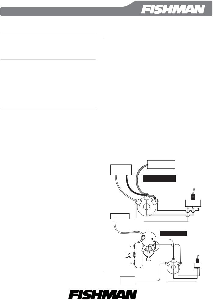
Powerbridge & magnetic pickups wired directly to a stereo jack
1. Connect the Powerbridge signal wire directly to the Ring terminal on the supplied stereo jack.
2.Connect the Powerbridge and magnetic grounds to the Sleeve terminal.
3.Connect the magnetic signal wire to the Tip terminal.
Passive volume for the Powerbridge
This circuit is easily assembled from ÒstockÓ guitar pots and components available at any electronics parts retailer.
You will need:
¥250k audio taper pot
¥330k resistor
¥820pF capacitor
¥1500pF capacitor
This network will attenuate the Powerbridge so that it better matches levels between magnetic and piezo pickups. You can expect a 14dB (nominal) decrease in Powerbridge output with this circuit.
Note: Optional 3-way selector switchÑif desired, a single pole, double throw (spdt) 3-way switch can also be added for piezo / magnetic pickup selection. Use a switch with an on-off-on orientation.
Powerbridge
Magnetic
Signal
Direct Wiring |
Optional 3-Way |
Selector Switch
|
|
|
Both |
|
|
|
|
Mag |
|
Piezo |
|
|
Tip |
Sleeve |
|
|
|
|
Ring |
|
|
|
|
|
|
ON |
OFF |
ON |
|
Powerbridge |
|
Stereo Jack |
|
|
|
|
|
|
|
|
|
|
|
250K − 300K |
|
|
|
|
|
Audio Taper P ot |
|
|
|
|
|
Passive Volume |
|
|
|
|
|
|
Optional 3-Way |
||
|
|
|
Selector Switch |
||
820 pF |
330 K |
Both |
|||
Mag |
|
Piezo |
|||
|
|
Sleeve |
|
||
|
|
|
|
|
|
|
|
Ring |
|
|
|
|
|
1500 pF |
O |
O |
O |
|
|
Tip |
F |
||
|
|
N |
N |
||
|
|
F |
|||
|
|
Stereo |
|
|
|
|
|
Output |
|
|
|
|
|
Jack |
|
|
|
Magnetic
Signal
www.Þshman.com |
514-300-113 Rev A 5-09 |
 Loading...