


ACOUSTIC BLENDER SYSTEM

ACOUSTIC
BLENDER
®
ACOUSTIC INSTRUMENT PREAMP
ACOUSTIC
BASS
BLENDER
®
ACOUSTIC BASS PREAMP
OWNER’S MANUAL
ACOUSTIC BLENDER SYSTEM
2
Thank you for your purchase of a FISHMAN product. Please read these instruc-
tions carefully. If you have any questions or problems, please feel free to call our
PRODUCT INFORMATION LINE at 978-988-9665.
The Acoustic BLENDER is a dedicated 2 channel preamp that addresses the
specific needs of acoustic stringed instrument players. The BLENDER System
combines the sounds from a pickup and instrument-mounted mini-microphone.
There are three basic components to the BLENDER System:
1) MICROPHONE and PICKUP:
A microphone alone is capable of capturing the natural ambience and resonance
of an acoustic stringed instrument. A single piezo pickup delivers a clear, bal-
anced, high output signal with low feedback. Combining the two sounds results
in tone quality and projection in which the sum is greater than the parts. Before
the BLENDER System, there was no simple and practical means to combine a
microphone and pickup for the performing acoustic musician.
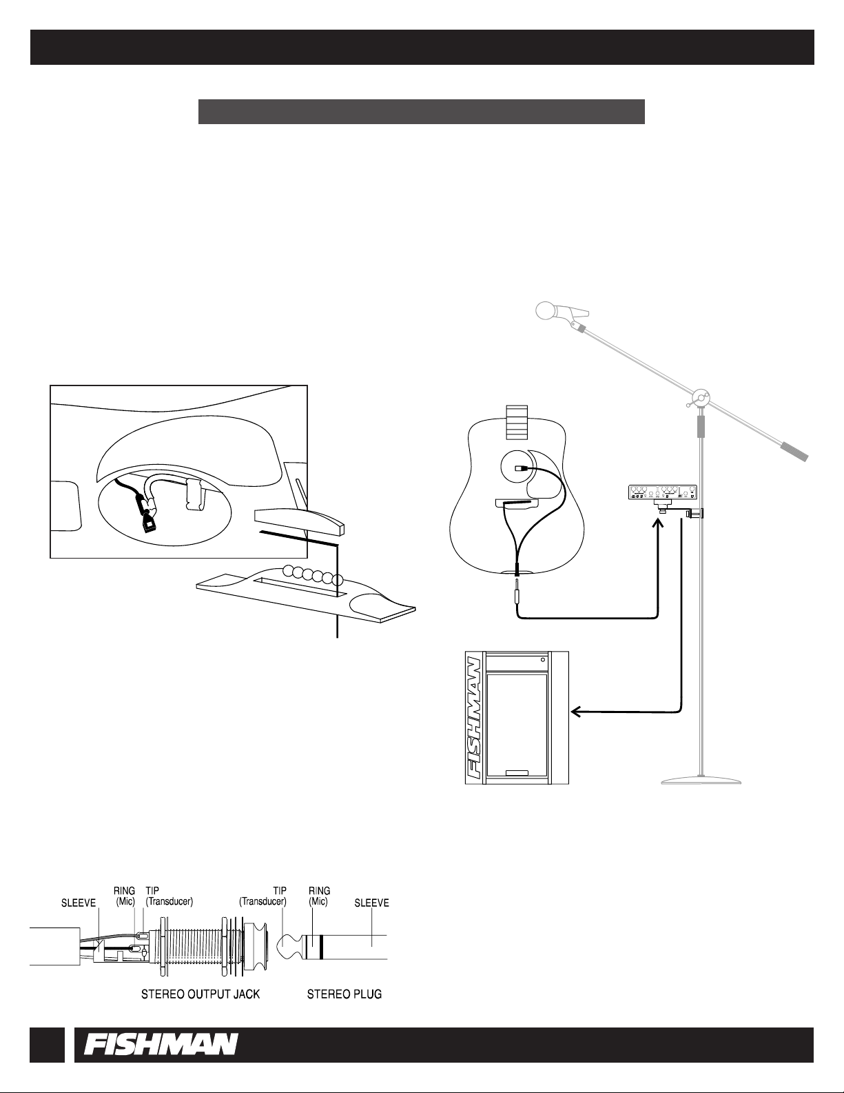
The mini-microphone is conveniently positioned on the instrument with a micro-
phone mount specifically designed for the application. This allows you the
unique opportunity of having a permanent microphone setup, precisely at the
instrument’s "sweet spot". The advantages of this are clear - especially to any-
one who has ever had to set up a microphone without a sound check - five min-
utes before the gig! With the BLENDER System, you can now arrive at the gig,
take your mic’ed instrument out of its case, plug in and play with complete free-
dom of movement.
2) STEREO INSTRUMENT CABLE:
The microphone and pickup signals are fed into a stereo jack (also called TRS or
Tip / Ring / Sleeve) that is mounted on the instrument. The two signals are then
routed through a stereo instrument cable (again,TRS) to the STEREO IN jack of
the BLENDER. The BLENDER provides low voltage Phantom Power to the mini-
microphone through the same cable.
With pickup and microphone wired to Tip and Ring respectively, and your instru-
ment connected by a stereo instrument cable to the BLENDER’s STEREO IN
jack, the pickup is controlled by the TRANSDUCER channel, and the microphone
is controlled by the MICROPHONE channel.
(See pages 12-13 for more information on Suggested Input Options.)
By consolidating the two signals plus phantom power, you save both setup time
and aggravation. The stereo instrument cable provides a simple solution to the
hassle of multiple cable runs and outboard phantom power supplies.
3) The BLENDER: The BLENDER is the brain of the System. The signals from
the instrument are sent to the MICROPHONE and TRANSDUCER channels.
Each channel is optimized for the particular input impedance, level, phase and
equalization needs of both microphone and pickup. The two signals are then
"blended" together and a composite signal can be sent to amplification, record-
ing, signal processing and/or broadcast gear.
NOTE: If your instrument has an onboard battery, and you want to route micro-
phone and pickup signals through a stereo instrument cable, you may need to
install a Fishman SMART SWITCH for the system to operate. (See Page 22)
INTRODUCTION: THE BLENDER SYSTEM
MINI-MICROPHONE MOUNTED ON
X-BRACE NEAR SOUNDHOLE
UNDER-SADDLE PIEZO TRANSDUCER
Before you begin using your Blender, you will need to have a pickup and microphone in place on your instrument.
Here are four common scenarios:
WARNING: INSTALLATION BY A QUALIFIED PROFESSIONAL REPAIRMAN IS STRONGLY RECOMMENDED. FISHMAN TRANSDUCERS WILL NOT BE RESPONSIBLE FOR ANY DAMAGES TO
YOUR INSTRUMENT DUE TO IMPROPER INSTALLATION.
ACOUSTIC BLENDER SYSTEM
3
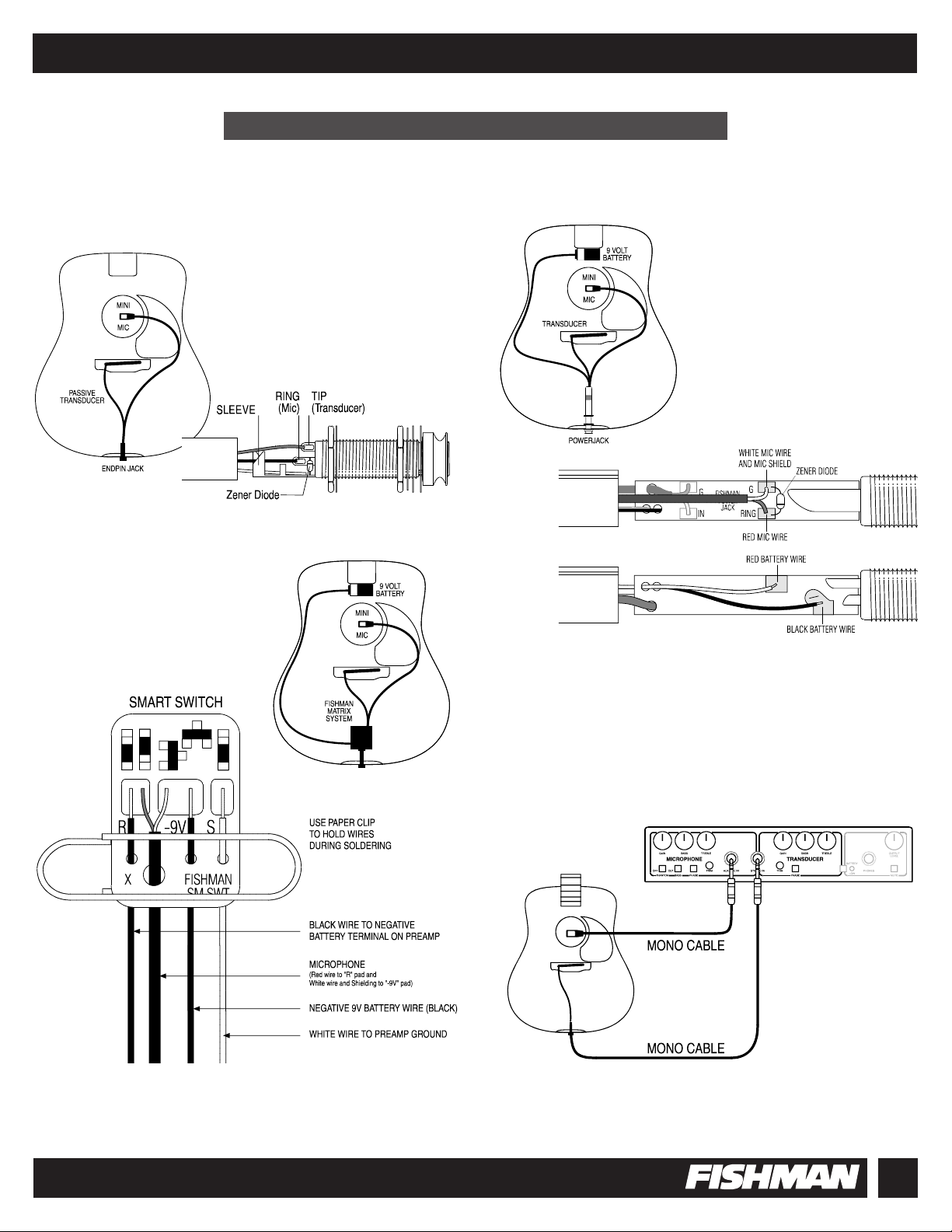
ACTIVE PICKUP AND MICROPHONE:
If your instrument has an active piezo pickup
- such as the Fishman Acoustic Matrix - you
will need a Fishman Smart Switch to connect
a microphone to the stereo endpin jack for
the system to operate. (See Page 22.)
PICKUP AND MICROPHONE
WITH SEPARATE MONO INSTRUMENT CABLES:
You may choose to route the pickup and microphone through
two separate mono instrument cables.
PREPARING YOUR INSTRUMENT
PASSIVE PICKUP
AND MICROPHONE:
If your instrument has a passive piezo
pickup, it’s easy to connect it and a
microphone to the same stereo endpin
jack. Connect the pickup to tip, and the
microphone to ring.
PICKUP WITH POWERJACK
AND MICROPHONE:
If your instrument has a piezo or magnetic
pickup and a Fishman Powerjack, connect
a microphone to the ring by soldering it to
the appropriate terminal on the Powerjack
circuit board.

ACOUSTIC BLENDER SYSTEM
4
QUICK START .......................................................4
FEATURES............................................................5
POWER
INPUT JACKS .......................................................6
FRONT PANEL - MICROPHONE CHANNEL ......................7
FRONT PANEL - TRANSDUCER CHANNEL......................9
FRONT PANEL - MASTER SECTION .............................10
REAR PANEL ......................................................11
SUGGESTED INPUT OPTIONS ............................12
SUGGESTED OUTPUT OPTIONS.........................14
EFFECTS LOOPS ................................................16
TROUBLESHOOTING ..........................................17
OPTIONAL ACCESSORIES
SPECIFICATIONS
BLOCK DIAGRAM...............................................18
APPENDIX I: THE MICROPHONE ........................19
APPENDIX II: PHASE..........................................21
APPENDIX III: SMART SWITCH ..........................22
LIMITED WARRANTY ..........................................24
You don't have to read this manual to get up and running, although we recom-
mend that you do in order to get the most out of your BLENDER.
Here's what you need to do if you want to "plug in and play".
COMPONENTS
1) ACOUSTIC BLENDER
2) 9 Volt Alkaline Battery
3) Pickup and mini-electret condenser Microphone connected to a
Stereo Jack
(TRS = Tip / Ring / Sleeve) See Page 3
4) Stereo Instrument Cable (TRS = Tip / Ring / Sleeve)
5) XLR or 1/4" Mono Instrument Cable
PROCEDURE
1) Lift the battery compartment lid on top of the BLENDER and install a fresh
9 Volt alkaline battery. Replace the lid.
2) With the stereo cable, connect the instrument to the STEREO IN jack
on the BLENDER front panel.
3) Set all front panel switches to the OUT position. Set both Gain controls
fully counter-clockwise. Set the Output Level to 3:00. Set Bass and Treble
controls to 12:00.
4) Run a cable from one of the MIX outputs on the back of the BLENDER
to your amp or PA system.
5) With the BLENDER Output level at 3:00, adjust both the MICROPHONE
and TRANSDUCER Gain controls to approximately the same volume level.
BATTERY OPERATION
Make note of the following precautions when using the BLENDER under battery power.
1) To avoid excessive battery drain:
a. Unplug the STEREO IN jack when the the unit is not being used.
b. When using the BLENDER without
a mini-electret microphone, be
sure the Phantom Power is OFF (switch is pushed IN).
Battery life is an estimated 15 hours continuous use.
2) To avoid hazardous TURN ON/OFF TRANSIENTS:
a. Always plug into the STEREO IN jack before turning on your amplifier
or PA System.
b. Always unplug the STEREO IN jack after turning off amplifier
or PA System.
3) Under battery power, the AUX / MIC IN jack will work only when the
STEREO IN jack is plugged in.
(See Page 12 #3)
CONTENTS
QUICK START
The BLENDER has no ON/OFF switch. Under battery power, the BLENDER
is turned on only when the STEREO IN jack is plugged in.
Power is always on when using an AC Adapter
(See Page 11).

FRONT PANEL
1) BATTERY COMPARTMENT: ( See Page 6 )
2) MICROPHONE GAIN: ( See Page 7 )
3) MICROPHONE BASS CONTROL: ( See Page 7 )
4) MICROPHONE TREBLE CONTROL: ( See Page 7 )
5) PHANTOM POWER OFF SWITCH: ( See Page 7 )
6) BASS CUT SWITCH: ( See Page 7 )
7) MICROPHONE PHASE SWITCH: ( See Page 8 )
8) MICROPHONE TRIM CONTROL: ( See Page 8 )
9) AUX / MIC IN: ( See Page 6 )
10) STEREO IN: ( See Page 6 )
11) TRANSDUCER GAIN CONTROL: ( See Page 9 )
12) TRANSDUCER BASS CONTROL: ( See Page 9 )
13) TRANSDUCER TREBLE CONTROL: ( See Page 9 )
14) TRANSDUCER TRIM CONTROL: ( See Page 9 )
15) TRANSDUCER PHASE SWITCH: ( See Page 9 )
16) BATTERY LOW LED: ( See Page 10 )
17) HEADPHONES OUTPUT: ( See Page 10 )
18) MUTE SWITCH: ( See Page 10 )
19) OUTPUT LEVEL CONTROL: ( See Page 10 )
REAR PANEL ( See Page 11 )
20) AC ADAPTER INPUT
21) 1/4" MIX OUTPUT
22) XLR MIX OUTPUT
23) RECESSED GROUND LIFT
24) XLR TRANSDUCER OUTPUT
25) 1/4" TRANSDUCER OUTPUT
26) MIX EFFECTS LOOP
27) TRANSDUCER EFFECTS LOOP
28) MICROPHONE EFFECTS LOOP
29) 1/4" MICROPHONE OUTPUT
30) XLR MICROPHONE OUTPUT
FEATURES
FRONT PANEL
REAR PANEL
ACOUSTIC BLENDER SYSTEM
5
Make note of the following precautions when using the BLENDER under battery power.
1) To avoid excessive battery drain (Battery life is an estimated 15 hours continuous use):
a. Unplug the STEREO IN jack when the the unit is not being used.
b. When using the BLENDER without a mini-electret microphone, be sure the Phantom Power is OFF
(switch is pushed IN).
2) To avoid hazardous TURN ON/OFF TRANSIENTS:
a. Always plug into the STEREO IN jack before
turning on your amplifier or PA System.
b. Always unplug the STEREO IN jack after
turning off amplifier or PA System.
3) Under battery power, the AUX / MIC IN jack will work only when the STEREO IN jack is plugged in.
(See Page 12 # 3)
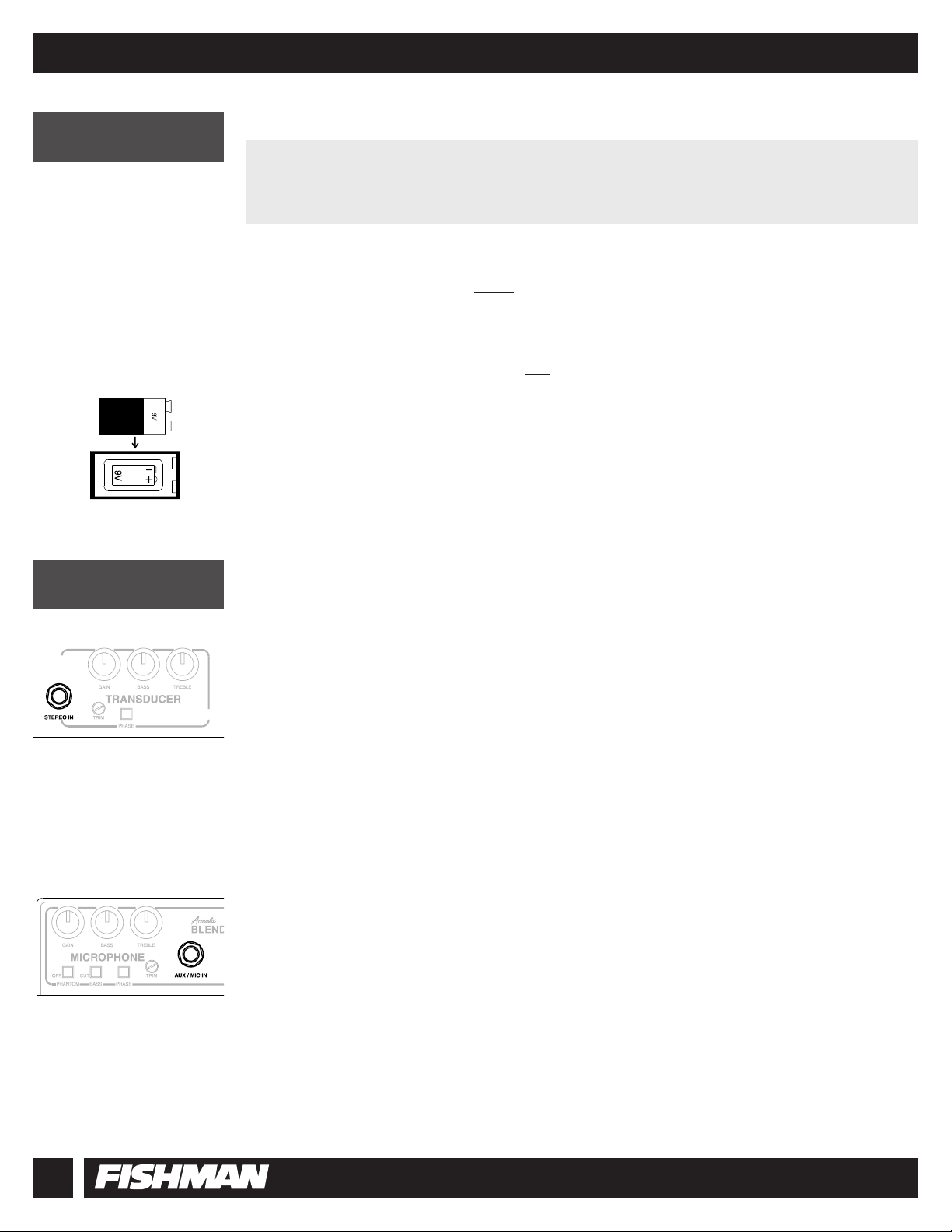
BATTERY COMPARTMENT
To replace the battery (See Page 10) lift the battery compartment lid on the top of the BLENDER
and install a 9 Volt alkaline battery.
STEREO IN
The STEREO IN jack is a TRS (Tip / Ring Sleeve) input that can accept two discrete signals through
a stereo instrument cable.
The STEREO IN jack can function in two modes:
1) MICROPHONE and TRANSDUCER CHANNELS OPERATION (Stereo Cable): Two signals from your instrument
(For example: Internal microphone and pickup) are routed through a stereo instrument cable to the STEREO IN jack.
The Ring signal goes to the MICROPHONE channel and the Tip signal goes to the TRANSDUCER channel.
2) TRANSDUCER CHANNEL ONLY OPERATION (Mono Cable): One signal from your instrument is routed through
a mono instrument cable to the STEREO IN jack. This signal goes to the TRANSDUCER channel.
AUX / MIC IN
Accepts a mono signal from a microphone or pickup. This signal is controlled by the the MICROPHONE channel.
The AUX / MIC IN jack can provide 4.5 Volt Phantom Power to a mini-condenser microphone.
This input can accept either magnetic or piezo pickups. Piezo signals will have a slight roll off at lower frequencies.
The AUX / MIC IN jack is an alternative to the Ring terminal of the STEREO IN jack.
Sometimes, using a stereo instrument cable for both of your signals is not practical. The AUX / MIC IN jack allows
you the option of sending two signals through separate mono instrument cables to both the AUX / MIC IN jack and
the STEREO IN jack.
AUX/MIC IN OVERRIDE: If you are sending two signals through the STEREO IN jack and you plug a third signal
into the AUX/MIC IN, the signal appearing at the RING of the STEREO IN jack will be replaced (overridden) by
the signal appearing at the AUX / MIC IN jack.
(See page 13 - #6)
BATTERY POWER
INPUT JACKS
ACOUSTIC BLENDER SYSTEM
6
The BLENDER has no ON/OFF switch. Under battery power, the BLENDER is turned on only when the
STEREO IN jack is plugged in.
Power is always on when using an AC Adapter (See Page 11).
ACOUSTIC BLENDER SYSTEM
7
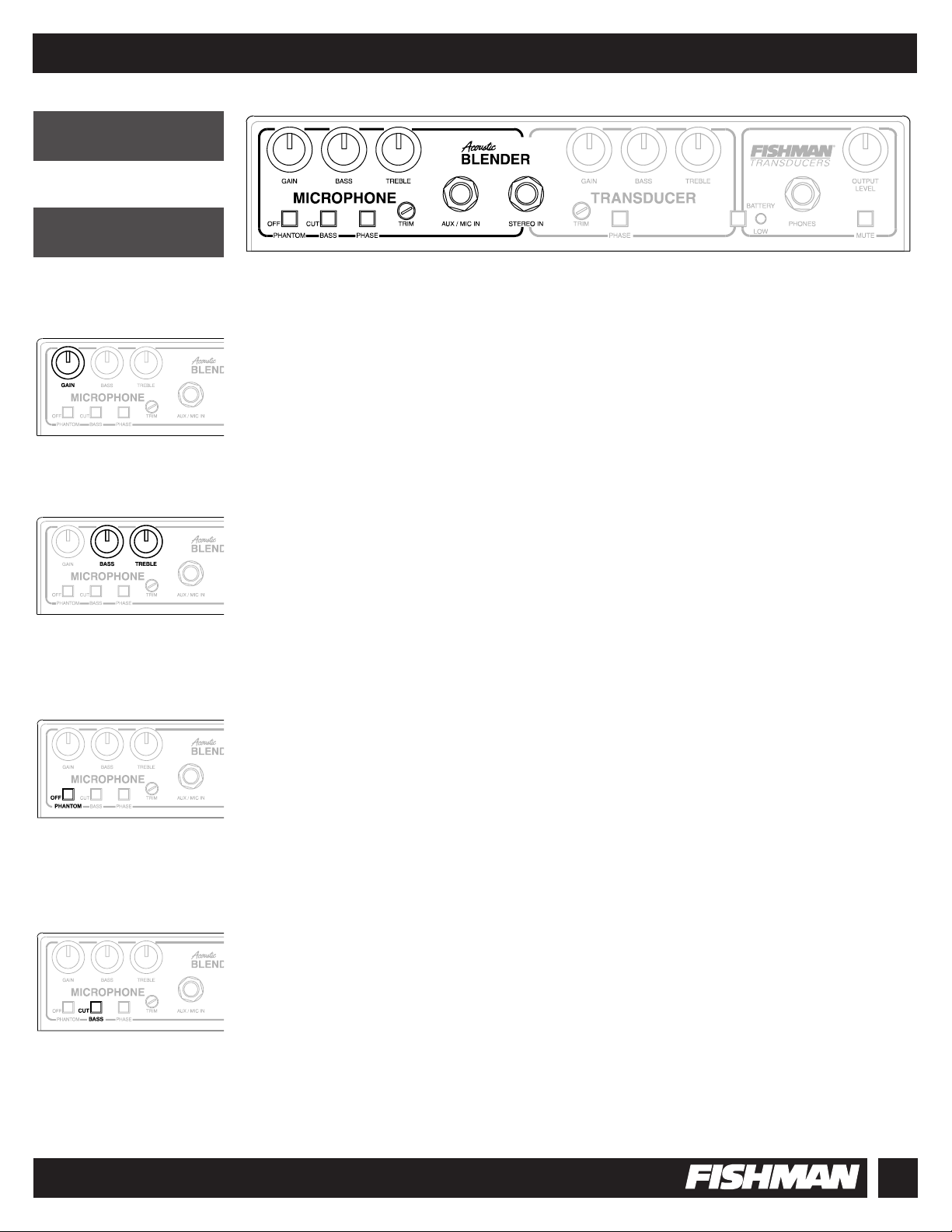
GAIN CONTROL
Controls the volume of the MICROPHONE Channel.
BASS and TREBLE CONTROLS
Controls the Bass and Treble for the MICROPHONE Channel.
These are boost / cut shelving tone controls. Setting them at 12:00 yields a flat response.
PHANTOM POWER OFF SWITCH
Pushing this switch IN shuts OFF the Phantom Power - for applications that use a dynamic microphone or pickup.
The OUT position provides 4.5 Volt Phantom Power to the Ring of the STEREO IN jack
OR the Tip of the AUX / MIC IN jack.
BASS CUT SWITCH
Pushing this switch IN rolls off bass frequencies from the MICROPHONE Channel.
This can be helpful in eliminating excessive boominess; especially in larger-bodied instruments.
In an amplified band situation, the Bass Cut may minimize microphone leakage from a bass guitar or a kick drum.
FRONT
PANEL
MICROPHONE
CHANNEL
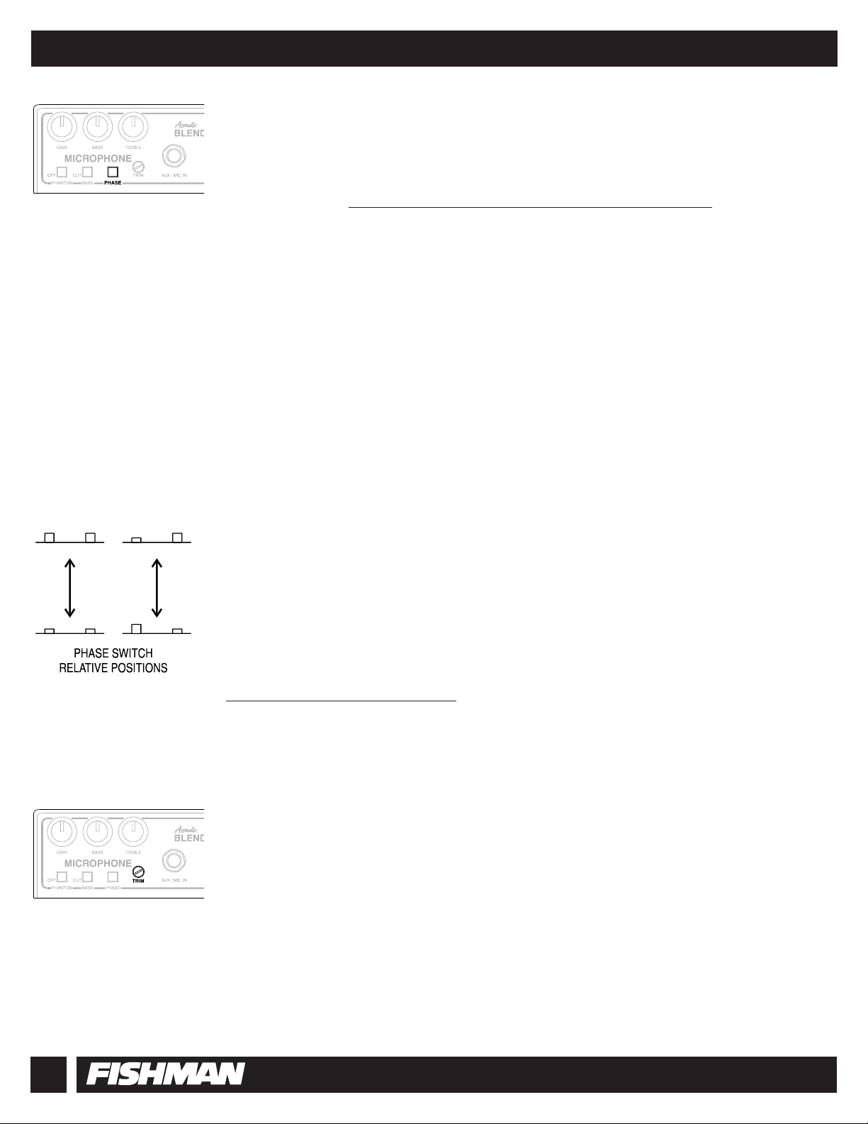
PHASE SWITCHES
Compensate for Phase differences that often occur between instrument, microphone, pickup and speaker.
HOW TO USE THE BLENDER’S PHASE SWITCHES
1. GET THE MICROPHONE PHASE ALIGNED WITH THE SOUND SYSTEM
Determine your position on stage.
Adjust the BLENDER output Level to 3:00 and the Transducer Channel Gain fully counter-clockwise.
Adjust the MICROPHONE Channel Gain to just below the threshold of feedback. Play a sustained note or chord on
your instrument while flipping the MICROPHONE Channel Phase switch. Listen to and compare each position.
Find the Phase switch position that yields the least low frequency (instrument cavity resonance) feedback.
If you decide to move more than a few feet from your playing position, you may need to repeat this test.
(See Page 21)
2. GET THE PICKUP IN PHASE WITH THE MICROPHONE
Having done part one of this test, raise the level of the TRANSDUCER Channel Gain control to suit your taste.
Play a sustained note or chord on your instrument while flipping the TRANSDUCER Channel Phase switch.
Listen to and compare each position. When the pickup and microphone are in Phase, the sound is full with lots
of deep bass. When out of Phase, the sound is thin with less bottom end.
3. MAKE NOTE OF THE RELATIVE POSITION OF BOTH PHASE SWITCHES
Once you have the BLENDER Phase aligned, note and memorize the relative position of both Phase switches.
They will be either in the same position, or one in and one out.
When you set up in a different venue, the Phase of the house sound system and room acoustics can contribute to
different Phase relationships compared to your previous gig. You will also find that the Phase issue depends a lot on
the exact performance setting; it tends to be a bigger problem in small rooms and less of a problem in large outdoor
setups.
To determine if there is a Phase difference at a new venue, play a sustained note or chord and invert both Phase
switches at once. Listen to and compare each position. The proper Phase switch position yields the least low fre-
quency (instrument cavity resonance) feedback.
See Page 21 for more information on Phase.
TRIM CONTROL
Sets the MICROPHONE Channel sensitivity for optimum signal strength before clipping.
To attain the best signal to noise ratio, start with the control fully clockwise and play your loudest note or chord.
If you hear distortion, lower the control with a small slotted screwdriver until the distortion disappears.
The Trim control can also be used to calibrate the MICROPHONE and TRANSDUCER Gain controls. If there is a
disparity between the signal strength of the two channels, use the Trim control to "normalize" the levels.
Try setting the Trim controls this way:
1) Set the Output Level to 3:00.
2) Set the MICROPHONE and TRANSDUCER Channel levels to 12:00.
3) Play a note or chord on you instrument and lower the MICROPHONE or TRANSDUCER Trim control
until both levels are equal, or are balanced to suit your taste.
ACOUSTIC BLENDER SYSTEM
8
 Loading...