


GAS RANGES
PROFESSIONAL
RGV-488, RGV-485GD, RGV-66, RGV-05, RGV-04
INSTALLATION GUIDE
US CA
!
WARNING!
SAFETY AND WARNINGS
!
WARNING!
If the information in this guide is not
followed exactly, a fire or explosion
may result causing property damage,
personal injury or death.
Do not store or use gasoline or other
flammable vapors and liquids in the
vicinity of this or any other appliance.
NEVER use this appliance as a space
heater to heat or warm the room. Doing
so may result in carbon monoxide
poisoning and overheating of the
appliance.
WHAT TO DO IF YOU SMELL GAS
• Do not try to light any appliance.
• Do not touch any electrical switch.
• Do not use any phone in your
building.
• Immediately call your gas supplier
from a neighbor’s phone.
• Follow the gas supplier’s instructions.
• If you cannot reach your gas supplier,
call the fire department.
Never operate the top surface cooking
section of this appliance unattended.
• Failure to follow this warning statement
could result in fire, explosion or burn
hazard that could cause property damage,
personal injury or death.
• If a fire should occur, keep away from the
appliance and immediately call your fire
department.
an oil/grease fire with water
Do not attempt to extinguish
Installation and service must be
performed by a qualified installer,
service agency or the gas supplier.
2
SAFETY AND WARNINGS
!
WARNING!
Electric Shock Hazard
Failure to follow this advice may result in
electrical shock or death.
• Before carrying out any work on the electrical
section of the appliance, it must be disconnected
from the mains electricitysupply.
• Connection to a good ground wiring system is
absolutely essential and mandatory.
• Alterations to the domestic wiring system must
only be made by a qualified electrician.
!
WARNING!
Tip Hazard
Failure to follow this advice may result in
death or seriousburns.
• To reduce the risk of tipping the appliance, the
appliance must be secured by properly installed
anti-tip device packed with the appliance.
!
WARNING!
Weight Hazard
Failure to follow this advice may result in
damage or personalinjury.
• Proper equipment and adequate manpower must
be used in moving the range to avoid personal
injury or damage to the unit or the floor. The unit
is heavy and rests on adjustable steellegs.
• Two persons are required to move the product
safely to the installation location.
• 30" product weight: 408lb (185kg)
• 36" product weight: 440lb (200kg)
• 48" product weight: 604-640lb (274-290kg)
!
WARNING!
Cut Hazard
Failure to use caution could result in injury.
• Take care: some edges are sharp.
• A child or adult can tip the range and be killed.
• Install the anti-tip device to the structure by
fastening the supplied bracket to the floor and
wall following the instructions for installing the
anti-tip device.
• Engage the anti-tip device.
• Re-engage the anti-tip device if the range
ismoved.
3

SAFETY AND WARNINGS
READ AND SAVE THIS GUIDE
WARNING!
To reduce the risk of fire, injury to persons or damage when using the appliance, follow the
important safety instructions listed below. Read all the guidance before using the appliance.
Servicing
z
Do not repair or replace any part of the appliance unless specifically recommended in
the user guide. All other servicing should be undertaken by a Fisher & Paykel trained and
supported service technician or qualified person.
z
Technicians must disconnect the power supply before servicing this appliance.
z
Please make this information available to the person installing the appliance.
z
This appliance must be installed and connected to the mains power supply only by a
suitably qualified person according to these installation instructions and in compliance
with any applicable local building and electricity regulations. Failuretoinstall the
appliance correctly could invalidate any warranty or liability claims.
Gas Requirements
z
Be sure that the unit being installed is set up for the kind of gas being used. The gasrange
is shipped from the factory set and adjusted for Natural Gas or LP (propane), depending
on the specific model ordered. Verify that the range is compatible with the gas at the
installation site before proceeding further.
z
Returnrange to dealer if the unit is not set for site gas supply.
General
z
The appliance must not be installed behind a decorative door in order to
avoid overheating.
z
The range must be grounded.
z
Installation must comply with your local building and electricity regulations.
z
Ensure the installer shows the customer where the gas supply shut-off valve is located.
z
A circuit breaker is recommended.
z
If the power supply cable is damaged, it must be replaced by the manufacturer, itsservice
agent or similarly qualified person in order to avoid a hazard.
z
Do not use adaptors, reducers or branching devices to connect the oven to
themainselectricity supply, as they can cause overheating and burning.
z
Improper installation, adjustment alteration, service or maintenance can cause property
damage, injury or death. Read the installation, operating and maintenance instructions
thoroughly before using, installing or servicing this appliance.
z
A risk of the appliance tipping over exists if the appliance is not installed in accordance
with installation instructions.
z
DO NOT obstruct the flow of combustion or ventilation air to the appliance.
Besureafresh air supply is available.
z
Check local building codes for the proper method of range installation. Localcodesvary.
Installation, electrical connections, and grounding must comply with all applicable codes.
In the absence of local codes, the range should be installed in accordance with the latest
edition of National Fuel Gas Code ANSI Z223.1 and National Electrical Code ANSI / NFPA 70.
z
In Canada: Installation must be in accordance with the current CAN/CGA B149.1&2 Gas
Installation codes and/or local codes. Electrical installation must be in accordance with the
current CSA C22.1 Canadian Electrical Codes Part 1 and/or local codes.
z
Do not lift the range by the door handle. Doing so may damage the product.
z
Before use, ensure all doors are correctly installed.
z
Always keep the appliance area clear and free from combustible materials, gasoline and
other flammable vapors and liquids.
4
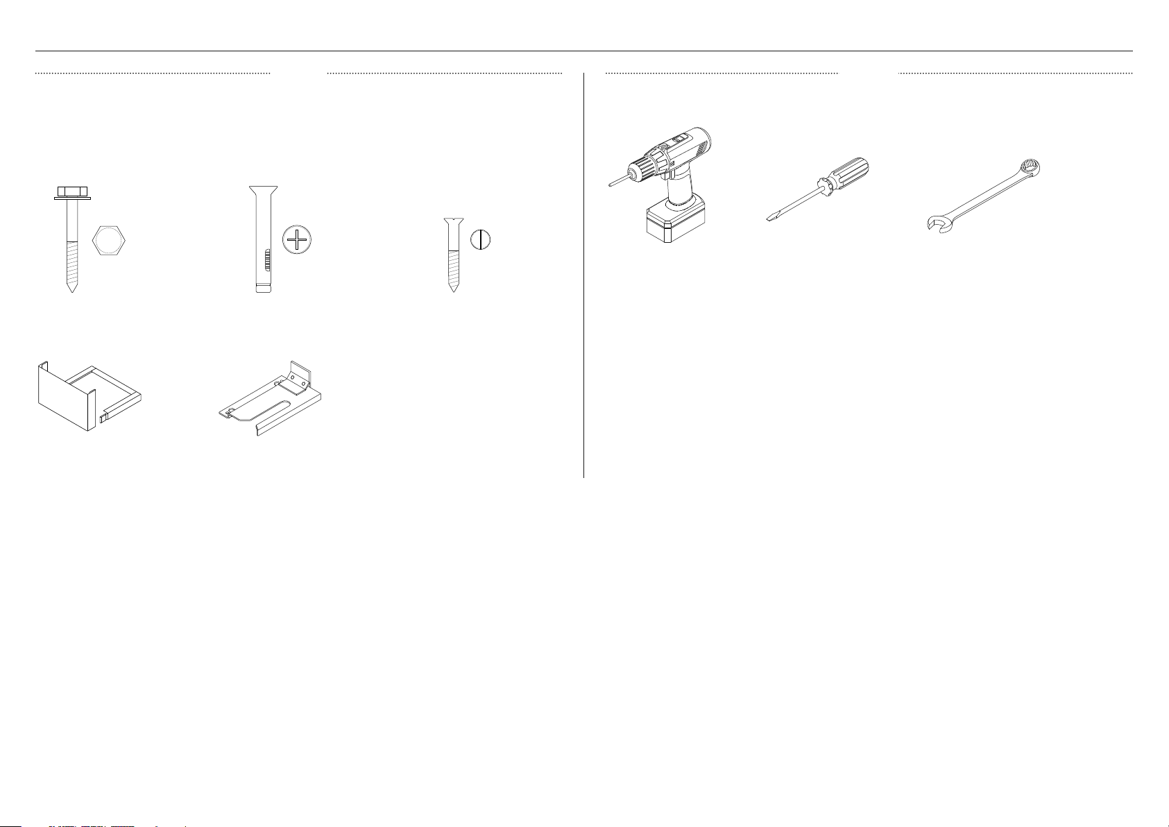
COMPONENTS REQUIRED
PARTS TOOLS
z
Keep all packing materials until the unit has been inspected.
z
Inspect the product to ensure there is no shipping damage. If any damage is detected
contact the dealer or retailer you bought the product from to report the damage.
z
Fisher & Paykel is not responsible for shipping damage.
Supplied
Not supplied
Lag bolts and washers (2)
Foot cover sets (2)
5/16" x 1 1/2" sleeve anchors (2)
Anti-tip bracket (2)
#10 x 2" wood screws (4)
Powered driver
Flat-head screw driver
15/16" spanner (2)
5
B
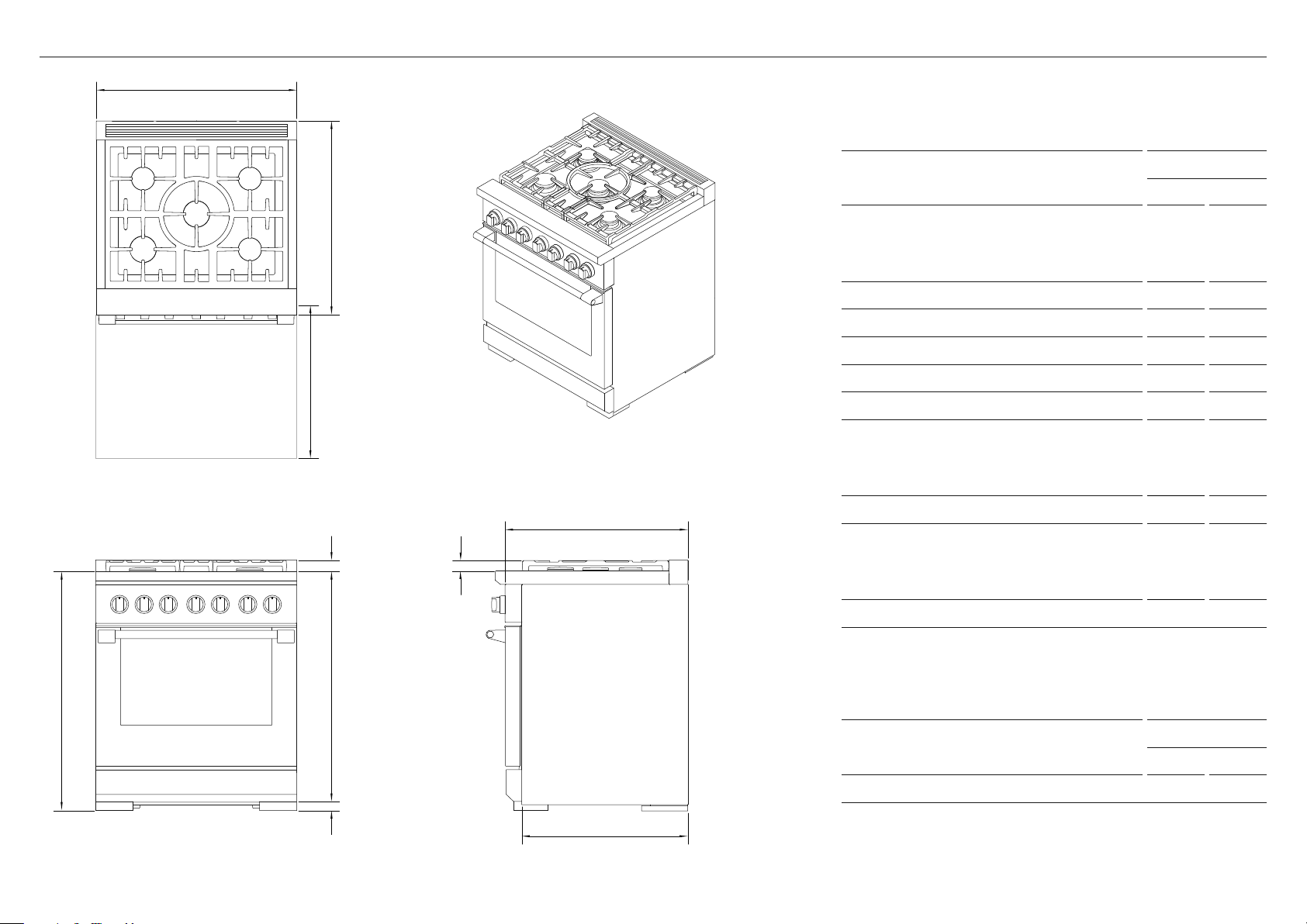
PRODUCT DIMENSIONS — 30" MODELS
A
PLAN
c
J
G F
h
ISOMETRIC
E
PRODUCT DIMENSIONS
30" MODELS
IN MM
A Overall height*
z
Min. (legs fully retracted) 35 3/4 908
z
Max. (legs fully extended) 36 3/4 933
B Overall width 29 7/8 759
C Overall depth 29 1/8 740
D Depth of chassis 25 3/8 644
E Depth from rear to control panel front 27 11/16 703
F Height from cook surface to top of burners 1 9/16 40
G Height from cook surface to top of trim
z
Vent Trim 1 3/4 45
z
Angled Vent Trim*** 3 1/2 90
H Height from cook surface to chassis base 35 1/4 895
I Height of adjustable feet
z
Min. (legs fully retracted) 1/2 13
z
Max. (legs fully extended) 1 1/2 38
J Depth of open door to front control panel 19 1/8 486
*excluding burners and trim
**excluding handle and dials
***purchased separately
PRODUCT WEIGHT
30" MODELS
LB KG
Overall weight (excluding packaging) 408 185
i
D
FRONT PROFILE
6
RGV3 305 model illustrated
Dimensions may vary by ± 2 mm
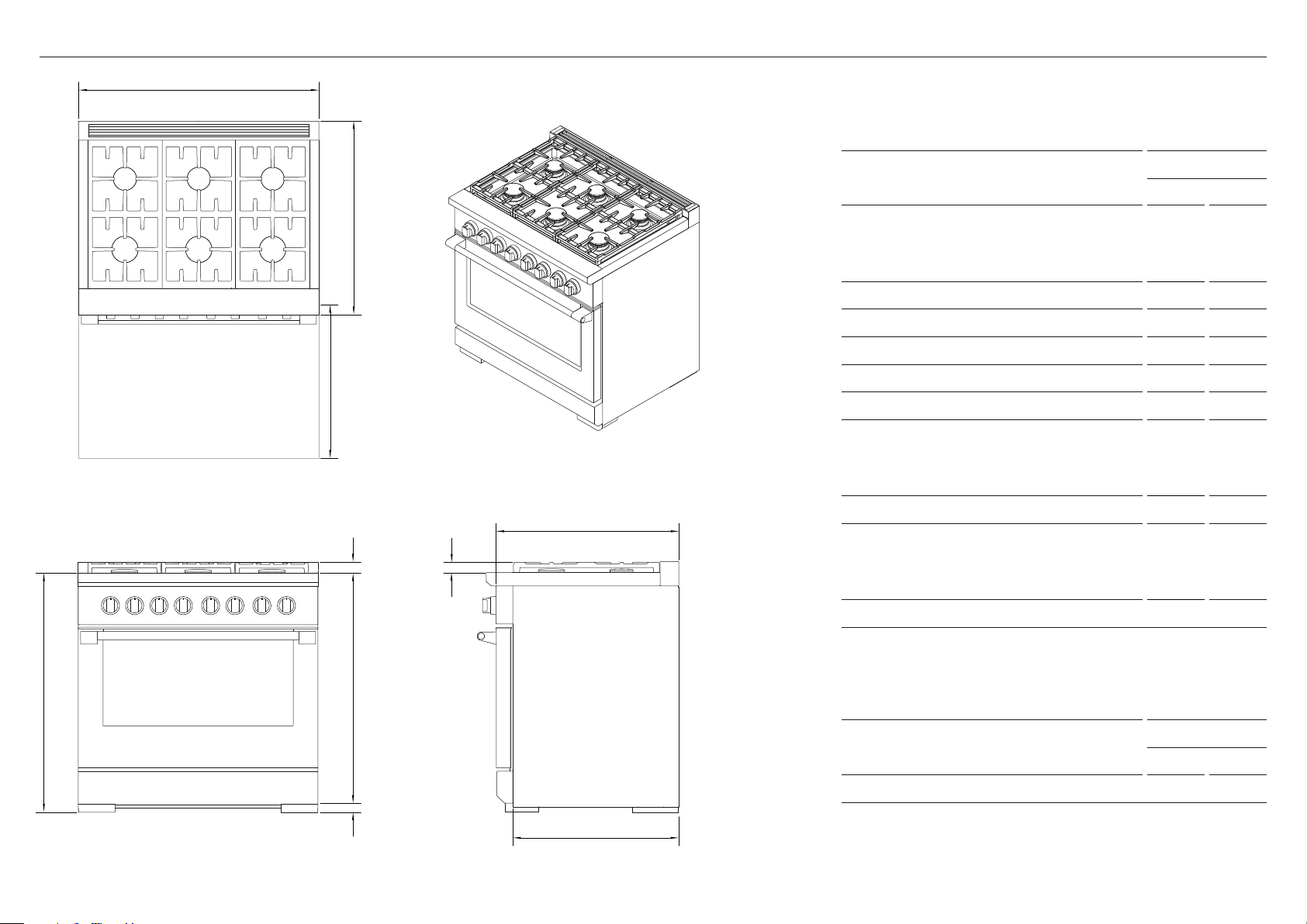
B
PRODUCT DIMENSIONS — 36" MODELS
A
PLAN
J
c
G
h
F
ISOMETRIC
E
PRODUCT DIMENSIONS
36" MODELS
IN MM
A Overall height*
z
Min. (legs fully retracted) 35 3/4 908
z
Max. (legs fully extended) 36 3/4 933
B Overall width 3 5 7/ 8 911
C Overall depth 29 1/8 740
D Depth of chassis 25 3/8 644
E Depth from rear to control panel front 27 11/16 703
F Height from cook surface to top of burners 1 9/16 40
G Height from cook surface to top of trim
z
Vent Trim 1 3/4 45
z
Angled Vent Trim*** 3 1/2 90
H Height from cook surface to chassis base 35 1/4 895
I Height of adjustable feet
z
Min. (legs fully retracted) 1/2 13
z
Max. (legs fully extended) 1 1/2 38
J Depth of open door to front control panel 19 1/8 486
*excluding burners and trim
**excluding handle and dials
***purchased separately
i
D
FRONT PROFILE
PRODUCT WEIGHT
36" MODELS
LB KG
Overall weight (excluding packaging) 440 200
RGV3 366 model illustrated
Dimensions may vary by ± 2 mm
7

B
PRODUCT DIMENSIONS — 48" MODELS
A
PLAN
J
c
G
h
F
ISOMETRIC
E
PRODUCT DIMENSIONS
48" MODELS
IN MM
A Overall height*
z
Min. (legs fully retracted) 35 3/4 908
z
Max. (legs fully extended) 36 3/4 933
B Overall width 47 7/ 8 1216
C Overall depth 29 1/8 740
D Depth of chassis 25 3/8 644
E Depth from rear to control panel front 27 11/16 703
F Height from cook surface to top of burners 1 9/16 40
G Height from cook surface to top of trim
z
Vent Trim 1 3/4 45
z
Angled Vent Trim*** 3 1/2 90
H Height from cook surface to chassis base 35 1/4 895
I Height of adjustable feet
z
Min. (legs fully retracted) 1/2 13
z
Max. (legs fully extended) 1 1/2 38
J Depth of open door to front control panel 19 1/8 486
*excluding burners and trim
**excluding handle and dials
***purchased separately
PRODUCT WEIGHT
48" MODELS
LB KG
Overall weight (excluding packaging)
604 –
640
274 –
290
i
D
FRONT PROFILE
8
RGV3 488 model illustrated
Dimensions may vary by ± 2 mm

CABINETRY DIMENSIONS
30" CABINETRY 36" CABINETRY
D
E
B
A
C
D
E
B
A
C
CABINETRY DIMENSIONS
30" MODELS
INCHES MM
A Max. height
z
Flush with counter 35 3/4 908
z
With levelling legs fully extended 36 3/4 933
B Depth
z
Flush with counter 27 11/16 703
z
Projecting control panel 25 1/8 638
C Width 30 762
D Max. depth of overhead cabinetry 13 330
E Min. width of ventilation hood required 30 762
CABINETRY DIMENSIONS
36" MODELS
INCHES MM
A Max. height
z
Flush with counter 35 3/4 908
z
With levelling legs fully extended 36 3/4 933
B Depth
z
Flush with counter 27 11/16 703
z
Projecting control panel 25 1/8 638
C Width 36 914
D Max. depth of overhead cabinetry 13 330
E Min. width of ventilation hood required 36 914
9

CABINETRY DIMENSIONS
48" CABINETRY CLEARANCES
D
E
The below clearances apply to both wall and island installations for all models.
Ensure the cook surface sits flush or above the adjacent countertop and any openings behind
or under the range are sealed. Flow of combustion and ventilation air must not be obstructed.
B
A
C
48" MODELS
CABINETRY DIMENSIONS
INCHES MM
A Max. height
z
Flush with counter 35 3/4 908
z
With levelling legs fully extended 36 3/4 933
B Depth
z
Flush with counter 27 11/16 703
z
Projecting control panel 25 1/8 638
C Width 48 1219
B
C
A A
C
ALL MODELS
CLEARANCE DIMENSIONS
INCHES MM
A Min. distance from side of range to nearest:
z
vertical combustible surface 12 305
B Min. distance from cook surface to overhead:
z
combustible surface 54 1372
z
combustible covering for ventilation hood 36 914
z
non-combustible surface 30 762
C Min. distance between countertop and cabinet 18 457
D Max. depth of overhead cabinetry 13 330
E Min. width of ventilation hood required 48 1219
10
Non-combustible surfaces: as defined in ‘National Fuel Gas Code’ (ANSI Z223.1, Current Edition). Clearances from noncombustible materials are not part of the ANSI Z21.1 scope and are not certified by UL. Clearances of less than 6" (152mm) must
be approved by the local codes and/or by the local authority having jurisdiction.

VENTILATION REQUIREMENTS
z
Ventilation hoods and blowers are designed for use with single wall ducting, however some local building codes or inspectors may require double wall ducting and/or a damper. Consultlocal
building codes and/or agencies before installing to ensure local requirements are met.
z
Hood blower speeds should be variable to reduce noise and loss of household air. The maximum speed should only be required when using the grill or SELF CLEAN.
z
Due to a high volume of ventilation air, a source of make-up air (outside replacement air) is recommended. This is particularly important for tightly sealed and insulated homes. A reputable
heating and ventilating contractor should be consulted.
WALL INSTALLATION ISLAND INSTALLATION
Non-combustible Non-combustibleCombustible Combustible
B b
B B
A A
A A
VENTILATION UNIT WALL INSTALLATION RECOMMENDATIONS
A min. 30" (762mm) max. 42 (762mm)
Hood
B min. 19" (480mm) max. 42 (762mm)
30" Range min. 550 CFM
VENTILATION UNIT ISLAND INSTALLATION RECOMMENDATIONS
A min. 30" (762mm) max. 42 (762mm)
Hood
B min. 19" (480mm) max. 42 (762mm)
30" Range min. 550 CFM
Blower
36" Range min. 550 CFM
48" Range min. 1100 CFM
Blower
36" Range min. 550 CFM
48" Range min. 1100 CFM
11

Non-combustible
BACKGUARD CONSIDERATIONS
BACKGUARD OPTIONSWALL SURFACE
max. 30"
(762mm)
NO BACKGUARD CUSTOM BACKGUARD
min. 6"
(152mm)
made from non-combustible materials
max. 1/2"
(13mm)
LOW THIN BACKGUARD HIGH THIN BACKGUARD
Combustible
RANGE
RANGE MOUNT
LOW BACKGUARD
NO BACKGUARD HIGH THICK BACKGUARD
WALL MOUNT
HIGH BACKGUARD, LOW SHELF
with angled trim
WALL MOUNT
HIGH BACKGUARD, HIGH SHELF
BACKGUARD WIDTH
INCHES MM
30" models BGRV2-1230 BGRV2-3030 BGRV3-3030H 29 7/8 759
36" models BGRV2-1236 BGRV2-3036 BGRV3-3036H 3 5 7/8 911
48" models BGRV2-1248 BGRV2-3048 BGRV3-3048H 4 7 7/ 8 1216
z
Installations against non-combustible surfaces: you may install the range without a backguard or choose any of the three backguards.
z
Installations close to combustible surfaces (above the cooking surface): without a backguard, there must be a min. 6" (152mm) clearance.
z
Installations immediately against combustible surfaces (above the cooking surface): you must purchase and fit the Wall Mount High
Backguard High Shelf and Angled Vent Trim.
z
Non-combustible surfaces: as defined in ‘National Fuel Gas Code’ (ANSI Z223.1, Current Edition). Clearances from non-combustible
materials are not part of the ANSI Z21.1 scope and are not certified by UL. Clearancesofless than 6" (152mm) must be approved by the
Note: Backguards can be purchased separately. All
ranges come fitted with an Integral Vent Trim only.
For more information on Backguard installation, refer to
the separate instructions provided with your backguard.
Backguard Installation Instructions can also be
downloaded from our website, www.fisherpaykel.com
local codes and/or by the local authority having jurisdiction.
12

ELECTRICAL REQUIREMENTS
The electrical supply must be a correctly polarized 120 VAC, 60 Hz, single phase circuit
suitable for the maximum current draw of the model, as detailed in the table below. Verify your
model’s current draw by checking the rating label on the back of the range.
This appliance is factory equipped with a power supply cord with a three-prong grounding
plug (with polarized parallel blades). It must be plugged into a mating grounding-type
receptacle, connected to a correctly polarized 120 VAC.
If the circuit does not have a grounding type receptacle, it is the responsibility and obligation
of the installer to have the existing receptacle changed to a properly grounded and polarized
receptacle in accordance with all applicable local codes and ordinances by a qualified
electrician. In the absence of local codes and ordinances, the receptacle replacement shall be
in accordance with the National Electrical Code.
The third prong should not, under ANY circumstances, be cut or removed.
MODEL MAX. CURRENT DRAW CIRCUIT FREQUENCY
RGV3-488 9 A 15 A 60 HZ
RGV3-485GD 15 A 15 A 60 HZ
RGV3-366 5 A 15 A 60 HZ
RGV3-304 5 A 15 A 60 HZ
RGV3-305 5 A 15 A 60 HZ
A wiring
diagram label
and the rating
label are
attached to
the back of
therange
z
This range must be connected to the mains power supply by a suitably qualified person.
z
This range must be grounded.
z
Always disconnect electric supply cord from the wall outlet or service disconnect before
servicing this appliance.
z
Observe all governing codes and ordinances when grounding, in absence of which, observe
National Electrical Code ANSI/NFPA No. 70.
13

GAS REQUIREMENTS
LP Gas
Connection: 1/2" NPT Minimum 5/8" dia. flex line. SupplyPressure: 11" to 14" W.C.
A regulator is required at the LP source to provide a maximum pressure of 14" W.C.
totherange regulator.
Natural Gas
Connection: 1/2" NPT Minimum 5/8" dia. flex line. SupplyPressure: 6" to 9" W.C.
z
The gas supply line must not protrude beyond the back of the appliance.
z
Ensure the gas supply is turned off at the wall valve before connecting the appliance.
z
Leak-testing of the appliance shall be conducted according to the manufacturer’s
instructions. See guidance on page 17.
z
The appliance must be isolated from the building’s gas supply piping system by closing its
individual manual shut-off valve during any pressure testing of the gas supply piping system
at test pressures equal to or less than 1/2 psig (3.5kPa.). The appliance and its individual
shut-off valve must be disconnected from the gas supply piping system during any pressure
testing of the system at the test pressures in excess of 1/2 psig (3.5kPa.). When checking
the manifold gas pressure, the inlet pressure to the regulator should be at least 7.0" W.C.
fornatural gas or 12.0" W.C. for LP.
z
The flex line for the gas supply must be metal and be approved for appliance use by a
certifying agency (CSA, CGA, or UL). Never use a hose made of rubber or other synthetic
material, as the heat may cause the hose to melt and develop leaks.
z
When hooking up the gas supply from the wall hard pipe to the range hard pipe, installation
length of flex line between range/wall hard piping must accommodate range being pulled
from wall for cleaning or servicing purposes. When range is pulled from wall, no strain
should occur at range or wall hard pipe connections.
The gas supply connections should be made by a qualified technician in accordance with local
codes or ordinances. In the absence of a local code, the installation must conform to the latest
edition of National Fuel Gas Code ANSI Z.223.1 (Warning: this appliance must be installed by a
licensed plumber or gas fitter when within the Commonwealth ofMassachusetts).
A manual shut-off valve (supplied by the installer) must be installed in an accessible location in
the gas line external to the appliance for the purpose of turning on or shutting off gas to the
appliance. (InMassachusetts such shut-off valves should be approved by the Board of State
Examiners of Plumbers & Gas Fitters.) Theshut-off valve must be located within 6 feet (1.8
meters) of the appliance it serves.
Fisher&Paykel recommends installing the manual shut-off valve in a location readily
accessible by the customer, so that gas to the appliance can be shut off in an emergency
situation. However, the appliance must not be modified to accommodate such placement.
Installer supplied manual
shut-off valve ‘open’ position
To range
To gas supply
Verify the type of gas supplied to the location. The range is shipped from the factory set up
andadjusted for Natural Gas or LP, depending on the specific model ordered.
Verify that the range is compatible with gas supply at the installation site before proceeding
further. Return the range to the dealer if the unit is not set for the gas supplied at the site.
14

UNPACKING THE RANGE
1. REMOVE TOE KICK
1
FRONT VIEW HINGE DETAIL
2 2
PROFILE VIEW PROFILE VIEW
Remove both screws to detach
the toe kick from the range.
Lift toe kick up and rotate
towards you to remove.
1
3. REMOVE FROM PALLET
2. REMOVE DOORS
Open the door completely and
open the hinge locks fully on
both sides.
Holding the door on both sides,
lift door back up to 45° and
carefully pull the door out and
away from the hinges.
1
2
3
* removal not required if range is secured at rear by brackets.
** model dependant.
Remove front bolts
Remove the two shipping
bolts made visible by
removing the toe kick.
Remove lower guard*
Unscrew the lower guard
panel from the back of
the range to remove.
Remove rear bolts or brackets**
Remove the two shipping bolts
or brackets.
packing sheet
IMPORTANT!
Two people required.
packing sheet
restraining
strap
Before restraining the product to the
hand truck, place two cardboard packing
sheets (shipped with the product)
against both side panels as shown.
Tilt the product and insert hand truck.
DO NOT insert the hand truck to the
front of the product.
Restrain the product and packing sheets
to the hand truck using straps and tilt
onto hand truck. Set pallet aside and pull
product to the installation location.
15
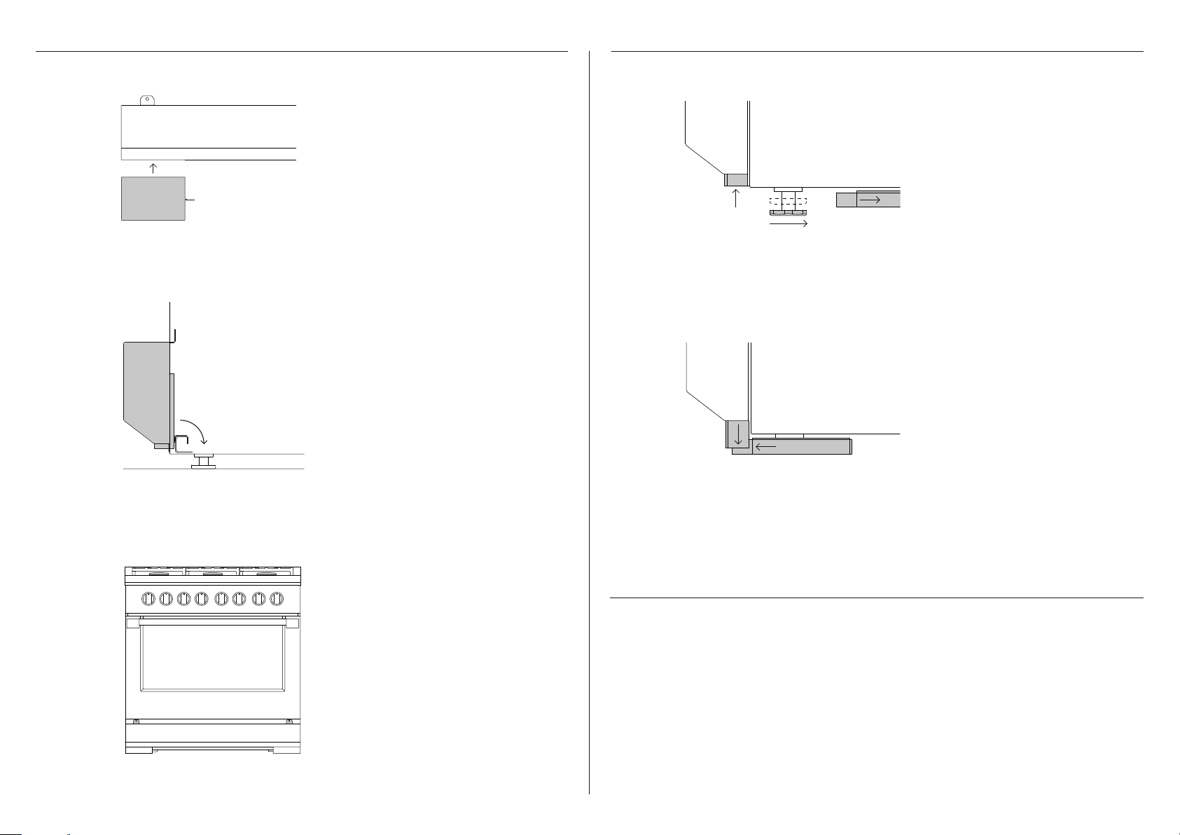
TOE KICK INSTALLATION LEVELLING THE RANGE
Insert both foot covers into
1 1
Long hem edge
FRONT VIEW
2 2
CROSS SECTION PROFILE VIEW PROFILE VIEW
the toe kick ensuring the long
hem edge is facing the inside of
the product.
Align the toe kick with side
panels of the range.
Clip into place by rotating and
pushing the bracket down over
the range structure.
To expose both front feet,
slide the interlocking foot
covers out of the way.
Turn feet to adjust the height.
PROFILE VIEW
Replace both sets of covers,
ensuring each set locks together.
PRIOR TO FINAL POSITIONING
z
Ensure the doors and toe kick panel are securely in place, if removed previously.
z
3
16
Check toe kick is flush with the
range and secure using 2 screws.
Ensure any backguard is fitted prior to final positioning. Refer to page 12 for all
backguard options.
z
Ensure all electrical and gas connections have been done as per instructions.
z
Ensure flooring and adjacent cabinetry are also level. To achieve a flush fit of the range to
adjoining countertops, it will be necessary to have level cabinets (front to back, and left to
right across opening of the range).

COOKTOP BURNERS LEAK TESTING
lifting off stable blue flameyellow tip
z
To check that the ignition system operates correctly, light each burner by itself, then all
burners in combination.
z
Check for a well-defined blue flame without any yellow tipping.
z
If any abnormality is evident, check that the burner assembly is located correctly.
z
When installing the burner port ring, align the two locating pins in the bottom side of the
port ring with the locating notch and center holes on the top side of the simmer ring, and
make sure these are properly engaged.
z
Incorrect installation may produce a dangerous flame and result in poor performance.
z
No air shutter adjustment is possible on the cooktop burners. Proper operation is achieved
with factory installed settings for the correct gas type.
z
If proper operation cannot be obtained, contact Customer Care or your nearest
Fisher&Paykel Authorized Service Center.
z
The range must not be used by the customer until proper operation has been achieved.
GAS
ON
z
Ensure all oven and burner knobs are set to OFF before connecting range to gas supply.
z
After final gas connection is made, turn gas supply on and test all connections in gas
supply piping for gas leaks with a soapy water solution.
z
In order to avoid property damage or serious personal injury, never use a Iit match or an
open flame to check for leaks.
If a leak is present: tighten joint or unscrew, apply more joint compound, tighten again and
retest connection for leak.
17

INFRARED BROIL AND OVEN BAKE BURNERS GRILL AND GRIDDLE BURNERS (SOME MODELS ONLY)
Air shutter
Blue flame
z
The oven infrared broiler burner has no air shutter and is not adjustable.
z
It is necessary to operate the oven broiler for 20-30 minutes to eliminate the harsh odor of
the insulation binder. This must be done before using the range for the first time and with
proper ventilation.
z
After approximately 5-8 minutes of operation the burner screen should be glowing red.
z
The oven bake burner has an air shutter and is adjustable.
z
Check for the proper burner flame characteristics and adjust air shutters if necessary.
Burner flames should be blue and stable with no yellow tips, excessive noise or lifting of the
flame from the burner. If any of these conditions exist, check that the air shutter or burner
ports are not blocked.
z
If the condition persists, adjust the air shutter as below:
z
If the flame is too yellow, indicating insufficient air open the shutter to increase air inlet.
z
If the flame is noisy or tends to lift away from the burner, indicating too much air, close the
shutter to reduce air inlet.
z
For warranty coverage, Fisher & Paykel requires that all burner adjustments be made by a
qualified technician at the time of installation. Improper adjustment will void your warranty.
z
Each valve and air shutter is individually tested and adjusted prior to shipment. Normally
adjustment is not required, however, vibration during transit, gas conversion or variations in
the local gas supply may make minor adjustments necessary.
z
Check for the proper burner flame characteristics and adjust air shutters if necessary.
Burner flames should be blue and stable with no yellow tips, excessive noise or lifting of the
flame from the burner. If any of these conditions exist, check that the air shutter or burner
ports are not blocked.
z
If the condition persists, adjust the air shutter as below:
z
If the flame is too yellow, indicating insufficient air open the shutter to increase air inlet.
z
If the flame is noisy or tends to lift away from the burner, indicating too much air, close the
shutter to reduce air inlet.
18

INSTALLING THE ANTI-TIP BRACKET
!
WARNING!
To reduce the risk of tipping the appliance, it must
be secured by properly installed anti-tip device
packed with theappliance.
• A child or adult can tip the range and be killed.
• Install the anti-tip device to the structure by fastening
the supplied bracket to the floor and wall following
the instructions for installing the anti-tip device.
• Engage the anti-tip device.
• Re-engage the anti-tip device if the range is moved.
All ranges must have an anti-tip device correctly installed as per the following instructions. If you pull
the range out from the wall for any reason, make sure that the device is properly engaged when you
push the range back against the wall. If it is not, there is a risk of the range tipping over and causing
injury if you or a child stand, sit or lean on an open oven door.
Instructions are provided for wood and concrete floors. Any other type of construction may require
special installation techniques as deemed necessary to provide adequate fastening of the anti-tip
bracket to the floor and wall. Theuse of this bracket does not preclude tipping of the range when not
properly installed.
Wood substrate
1 Place the bracket against the back wall,
into the right rear corner where
the range is to be located. Leave a 1/2"
(13mm) gap between the wall (or side of
range) and the bracket, as shown.
2 Drill 1/8" diameter pilot holes in the center
of the two small holes. A nail or awl may
be used if a drill is not available.
3 Fasten the bracket securely to the floor
and wall.
Once installed
Check for proper installation of the range and anti-tip bracket by grasping the back of the range
and carefully attempting to tilt it forward.
Concrete or cement substrate
1 Locate the bracket as shown.
2 Using the bracket as a template, drill (x2)
5/16" diameter pilot holes in the center
of the larger holes to a depth of at least
1 3/4".
3 Place the sleeve anchors into the holes
and use a hammer to tap them all the
way in.
4 Tighten the nuts on the sleeve anchors to
fasten the bracket securely to the floor.
Locating the bracket Securing the range
Wood
Concrete
1/2" (13mm)
Right rear foot
slides under bracket
19

TO BE COMPLETED BY THE INSTALLER
GENERAL
Specified clearance maintained.
FINAL CHECKLIST
GAS
Site gas supply iscompatible with range.
Backguard installed if clearance to combustibles behind unit is less than 6" (152mm).
Anti-tip bracket is correctly installed.
Unit is level–front to back and side to side.
Griddle (if equipped) and burner pan supports are level and does not rock.
All packaging materials have been removed. Check below grate and inside the oven.
Oven door hinges seated and door opens and closes properly.
Dials turn correctly and freely.
Burners light satisfactorily, both individually and with other burners operating.
Flame adjustments made if required.
Front toe kick panel in place and two screws are secure.
Complete and keep for safe reference:
LP Connection: 1/2" NPT Minimum 5/8" dia. flex line. SupplyPressure: 11" to 14" W.C.
NG Connection: 1/2" NPT Minimum 5/8" dia. flex line. SupplyPressure: 6" to 9" W.C.
Manual gas shut-off valve installed in an accessible location.
Unit tested and free of gas leaks.
ELECTRICAL
Receptacle with correctly rated and over-current protection is provided for service
cordconnection.
Adequate ground connection.
Model
Serial no.
Purchase date
Purchaser
Dealer address
Installer’s name
Installer’s signature
Installation company
Installation date
20

FISHERPAYKEL.COM
© Fisher & Paykel Appliances 2020. All rights reserved.
The models shown in this guide may not be available in all markets
The product specifications in this guide apply to the specific products and
models described at the date of issue. Under our policy of continuous product
improvement, these specifications may change at any time.
For current details about model and specification availability in your country,
please go to our website or contact your local Fisher&Paykel dealer.
and are subject to change at any time.
59218A 05.20
 Loading...