

Fisher & Paykel OR90 Series, OR90SCG4, OR90SDG4, OR90SCG6, OR90SDG6 Installation Manual

OR90 Dual Fuel
models
FREESTANDING COOKER
INSTALLATION GUIDE
GB IE
591554B / 1105508-ß1 11.18
3
1SAFETY AND WARNINGS
IMPORTANT!
SAVE THESE INSTRUCTIONS
The models shown in this installation guide may not be available in all markets and are subject to change at any time. For current details about model and specification availability in your country,
please go to our website fisherpaykel.com or contact your local Fisher & Paykel dealer.
IMPORTANT SAFETY INSTRUCTIONS
This appliance must be installed and serviced only
by a suitably qualified and registered person, and in
accordance with the current editions of the following
standards and regulations or other locally applicable
regulations:
-Gas Safety (Installation and Use) Regulations
-Building Regulations
-British Standards
-Regulations for Electrical Installation
Incorrect installation, for which the manufacturer
accepts no responsibility, may cause personal injury or
damage and could invalidate any warranty or liability
claims.
Be sure that the appliance being installed is set up for
the kind of gas being used. The gas cooker is shipped
from the factory set and adjusted for Natural Gas.
It can be converted for use with LPG following the
instructions in this manual.
Do not modify this appliance.
Do not use or store flammable materials on or near
this appliance.
Packing elements (eg plastic bags, polystyrene foam,
staples, packing straps etc) and tools should not be
left around during and after installation, especially if
they are within easy reach of children, as these may
cause serious injuries.
Some appliances are supplied with a protective film on
steel and aluminium parts. This film must be removed
before using the cooker.
IMPORTANT SAFETY INSTRUCTIONS
Particular attention shall be given to the relevant
requirements regarding ventilation.
Read these instructions carefully before installing this
product.
Please make this information available to the person
installing the appliance as it could reduce your
installation costs.
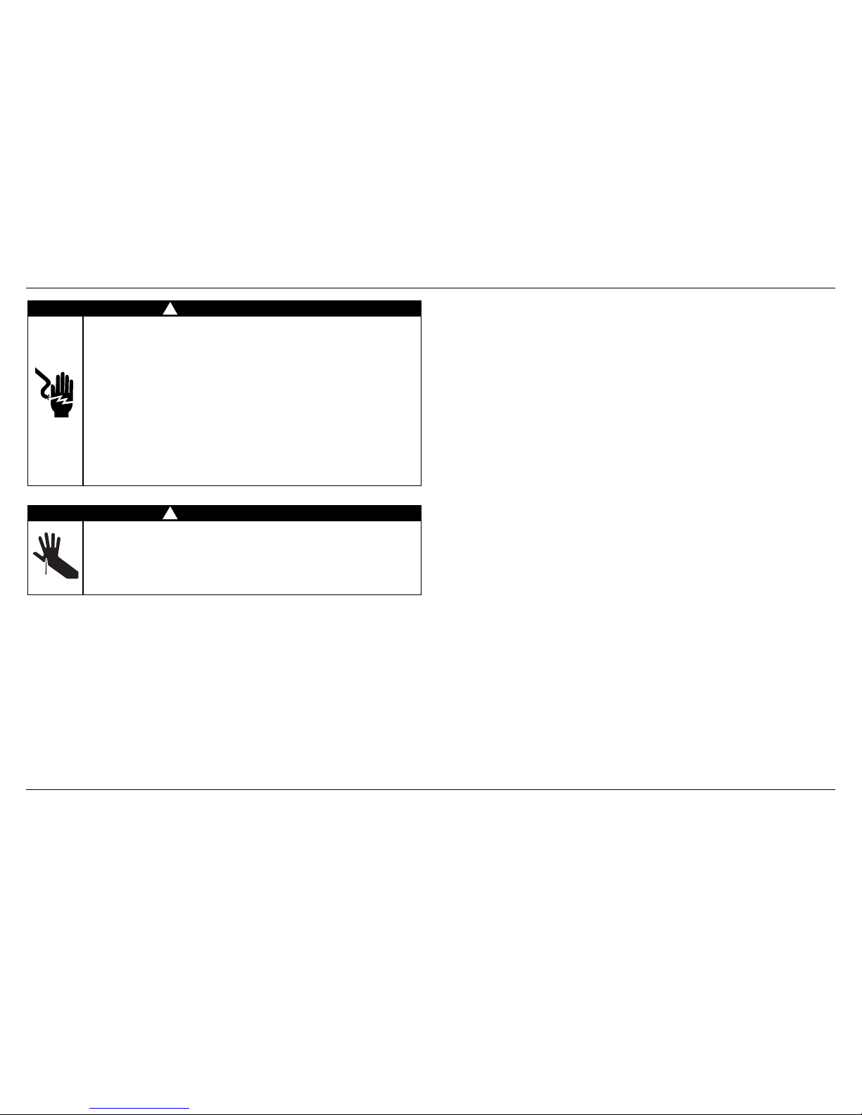
WARNING!
Electrical Shock Hazard
Before carrying out any work on the
electrical section of the appliance, it must be
disconnected from the mains electricity supply.
Connection to a good earth wiring system is
absolutely essential and
mandatory.
Alterations to the domestic wiring system must
only be made by a qualified electrician.
Failure to follow this advice may result in
electrical shock or death.
WARNING!
Cut Hazard
Take care - panel edges are sharp.
Failure to use caution could result in injury or
cuts.
!
!

4
Cleaning and servicing
Service should only be performed by an authorised technician.
When removing appliance for cleaning and/or service:
Shut off gas at main supply.
Disconnect AC power supply.
Disconnect gas line to the inlet pipe.
Carefully remove the cooker by pulling outward.
CAUTION: Cooker is heavy; use care in handling.
The misuse of oven door (eg stepping, sitting, or leaning on them) can result
in potential hazards and/or injuries.
When installing or removing the cooker for service, a rolling lift jack should be used.
Do not push against any of the edges of the cooker in an attempt to slide it into or
out of the installation. Pushing or pulling a cooker (rather than using a lift jack) also
increases the possibility of bending the leg spindles or the internal coupling connectors.
IMPORTANT!
Cooker is heavy, use care in handling.
Do not lift the cooker by the oven door handle or hob rail, or by lifting the cooktop trim
as this may damage the appliance.
Replacement parts
Only authorised replacement parts may be used in performing service on the cooker.
Replacement parts are available from factory authorised parts distributors.
Contact the nearest parts distributor in your area.
2GENERAL INSTALLATION INFORMATION
PRODUCT LABEL
5
IMPORTANT!
THIS APPLIANCE MUST BE INSTALLED BY A QUALIFIED INSTALLER.
Improper installation, adjustment, alteration, services, or maintenance can cause injury or property damage.
Consult a qualified installer, service agent, or the gas supplier.
The use of suitable protective clothing/gloves is recommended when handling or installing this appliance.
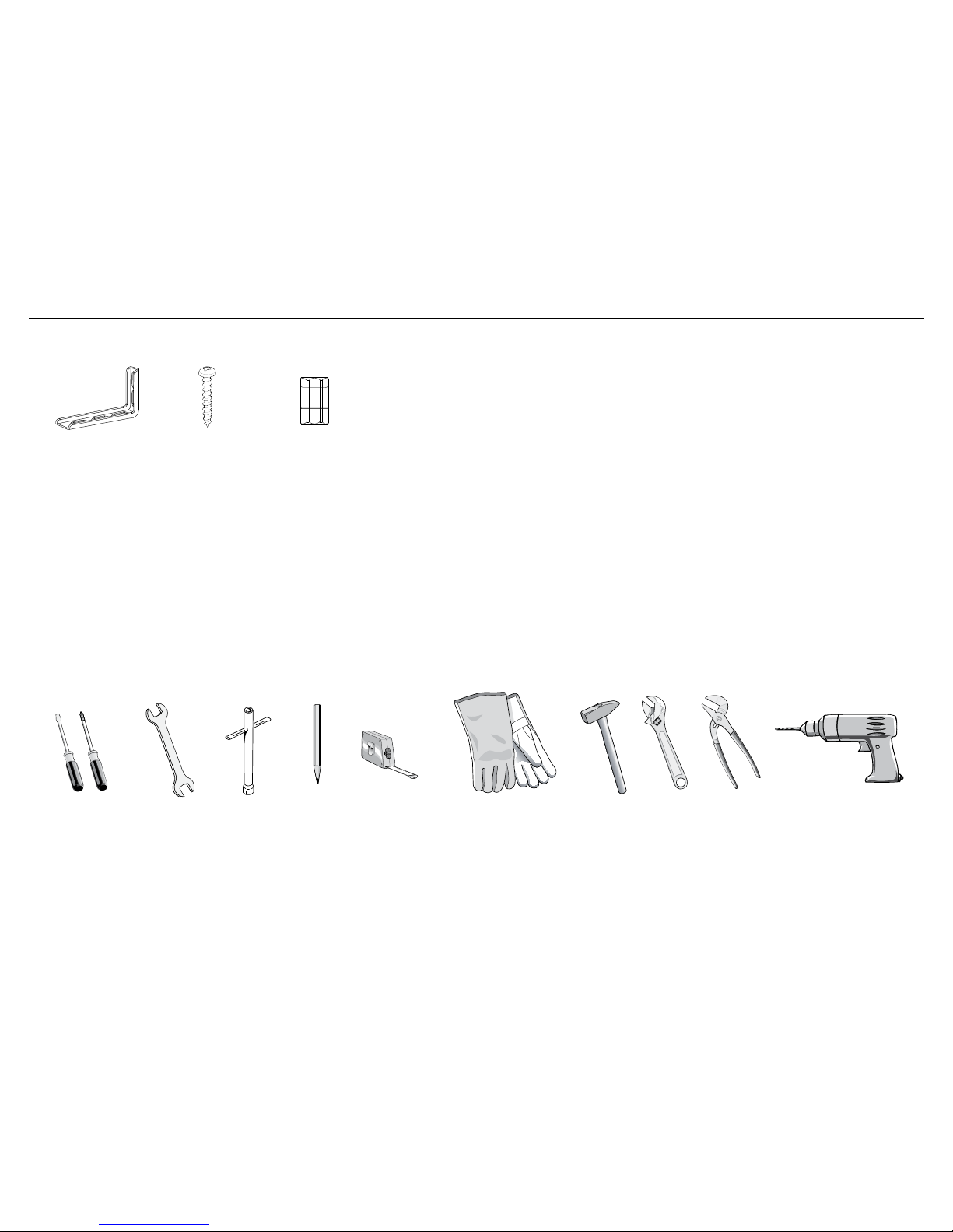
3PARTS SUPPLIED FOR INSTALLATION
4TOOLS NEEDED FOR INSTALLATION (NOT SUPPLIED WITH THE APPLIANCE)
1/2” cylindrical
connector and
fibre washer (1)
Screwdriver 2 – Wrench T-handle
wrench
Pencil Tape measure Suitable
protective gloves
Hammer Adjustable
wrench
Adjustable
pliers
Drill
3PARTS SUPPLIED FOR INSTALLATION
Screws and plastic
sleeve anchors (2)
Anti-tip bracket (1)
6
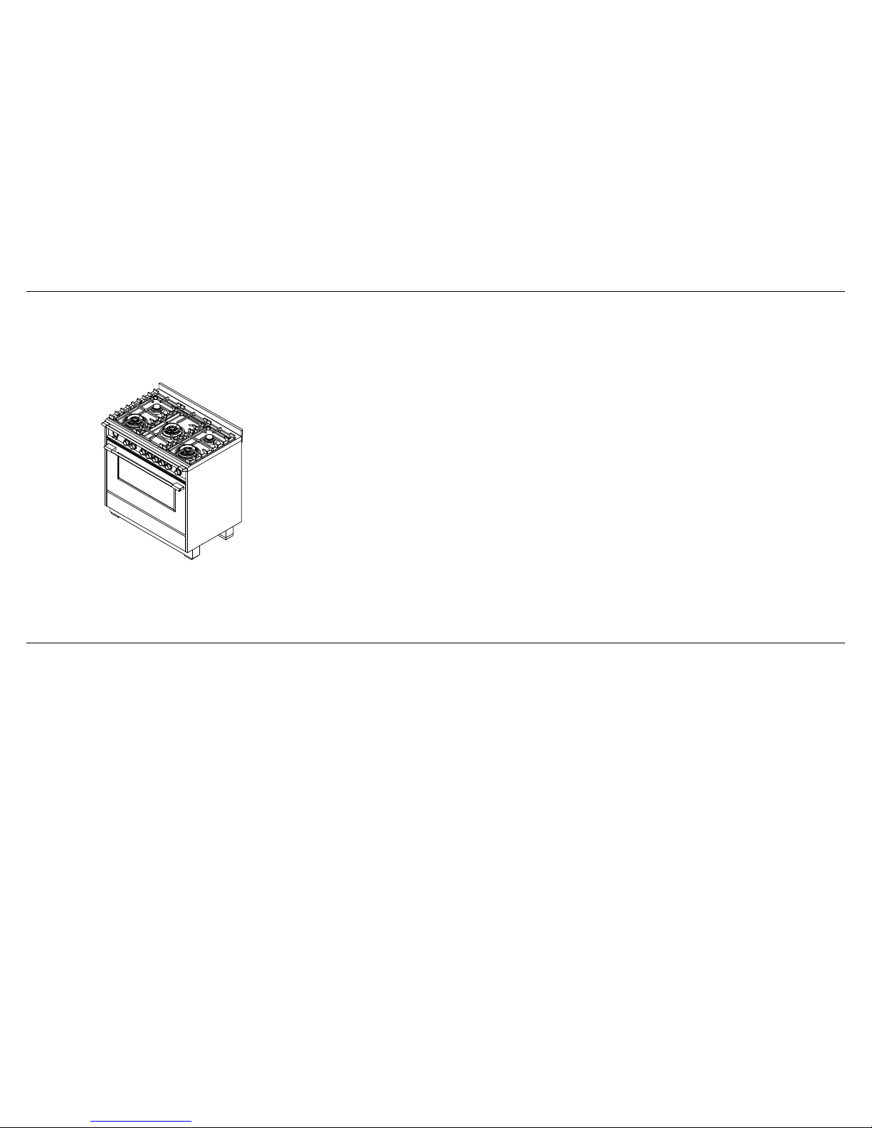
5MODEL IDENTIFICATION
OR90SCG4
OR90SDG4
OR90SCG6
OR90SDG6
Model features may vary
OR90 MODELS
6PRIOR TO INSTALLATION
Unpacking and handling
Inspect the cooker to verify that there is no shipping damage. If any damage is detected, call the shipper and initiate a damage claim. Fisher & Paykel is not responsible for shipping damage.
DO NOT discard any packing material until the cooker has been inspected.
Remove the outer carton and any packing material from cooker. Some models are supplied with a protective film on steel and aluminum parts.
This film must be removed before installing or using the appliance.
7
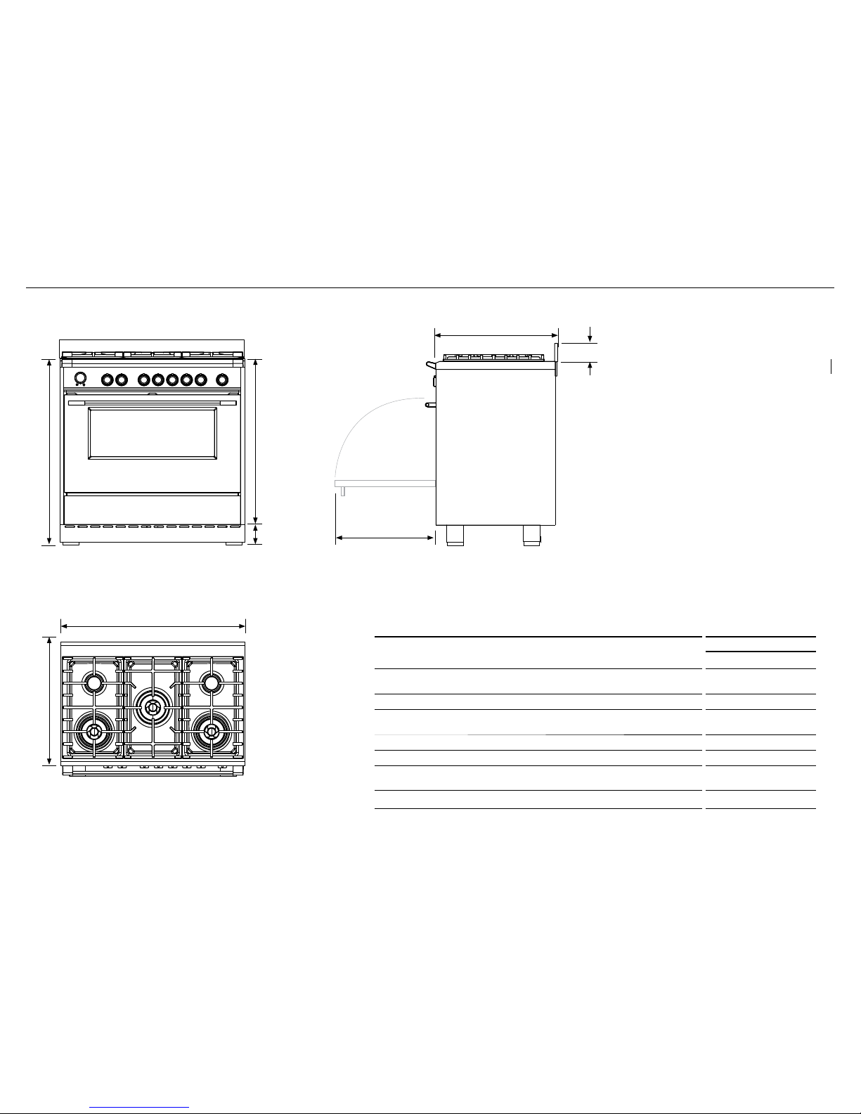
7PRODUCT DIMENSIONS
PRODUCT DIMENSIONS
OR90 DUAL FUEL
mm
A
Overall height of cooker
(from floor to top of cooktop, excluding grates and optional backguard)
min. 898
max 946
B
Overall width of cooker
897
C
Overall depth of cooker
(from front of cooker to rear of backguard, excluding handles and dials)
600
D
Height of optional backguard from top of cooktop
60
E
Height of chassis (excluding adjustable feet)
813
F
Adjustable feet height
min. 85
max. 133
G
Depth of open door to front of cooker
451
FRONT
TOP
SIDE
E
B
C
C
A
D
F
G
NOTE: Model features may vary
Optional kickstrip is available (purchased separately)
8
8CLEARANCE DIMENSIONS
Note
The cooker must be installed by a
suitably qualified technician and in
compliance with local safety standards.
This cooker has class “2/1” overheating
protection so that it can be installed
next to a cabinet
If the cooker is installed adjacent to
furniture which is higher than the gas
hob cooktop, a gap of at least 200 mm
must be left between the side of the
cooker and the furniture.
The walls and kitchen furniture
surrounding the appliance must be
made of non-flammable material. Any
veneered synthetic material and the glue
used must be resistant to a temperature
of 90°C in order to avoid ungluing or
deformations. It is recommended that a
10 mm gap to each side is made if the
adjacent kitchen furniture is made of a
plastic laminate wrap.
Curtains must not be fitted immediately
behind appliance or within 500 mm of
the sides.
Installing the cooker on a plinth
We do not recommend the cooker
is installed on a plinth. If this is
unavoidable, the cooker can be installed
on a plinth without the adjustable feet
fitted.
Ensure the cooker is secure and provide
safety measures to keep it in place.
Cabinetry dimensions can be adjusted
to suit the plinth height, see product
dimensions for chassis height.
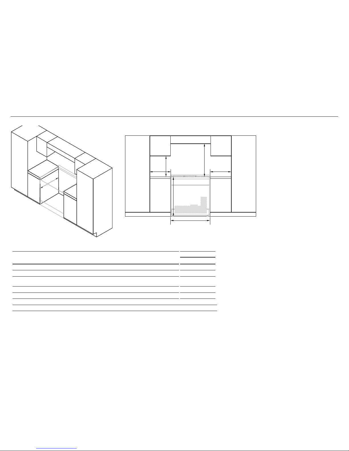
CLEARANCE DIMENSIONS
OR90 DUAL FUEL
mm
A
Minimum vertical distance between benchtop and cabinet extending above counter 450
B
Minimum clearance from left and right edge of cooker to nearest vertical combustible surface
200
C
Minimum clearance from cooking surface to:
– Overhead cabinet centered above the cooktop– Ventilation hood centered above the cooking surface 650
D
Width of cabinetry opening 900
E
Maximum height of cabinetry immediately adjacent to the cooker (from floor to countertop)*
946
F
Maximum depth from wall to cabinetry face
600
* Depending on the height of the feet adjustment. The cooking surface must sit flush or above benchtop level.
COOKING SURFACE
Electrical & Gas
(see diagrams following)
ISO
FRONT
A
C
d
e
F
b
b
 Loading...