

Fisher & Paykel OR90SDBSX Installation Instructions And User Manual

UAE
Installation instructions
and User guide
Freestanding cooker
OR90SDBSX models


1
Safety and warnings
2
Installation instructions
6
Using your seven-function oven for the first time
14
Setting the clock
15
Using your oven
16
Cooking functions
17
Using the rotisserie
20
Using the timer
22
Automatic cooking
23
Using your ceramic glass cooktop
24
Cooktop frequently asked questions
28
Cooktop troubleshooting
29
Care and cleaning
30
Warranty and service
44
Important!
SAVE THESE INSTRUCTIONS
The models shown in this document may not be available in all markets and are
subject to change at any time. For current details about model and specification
availability in your country, please go to our website www.fisherpaykel.com or
contact your local Fisher & Paykel dealer.
Contents
2
Safety and warnings
Important safety precautions
General
To avoid hazard, follow these instructions carefully before installing or using this product.
Please make this information available to the person installing the product as it could
reduce your installation costs.
Installation must comply with your local building and electricity regulations.
Failure to install the cooker correctly could invalidate any warranty or liability claims.
Some appliances have a protective lm. Remove this lm before using the cooker.
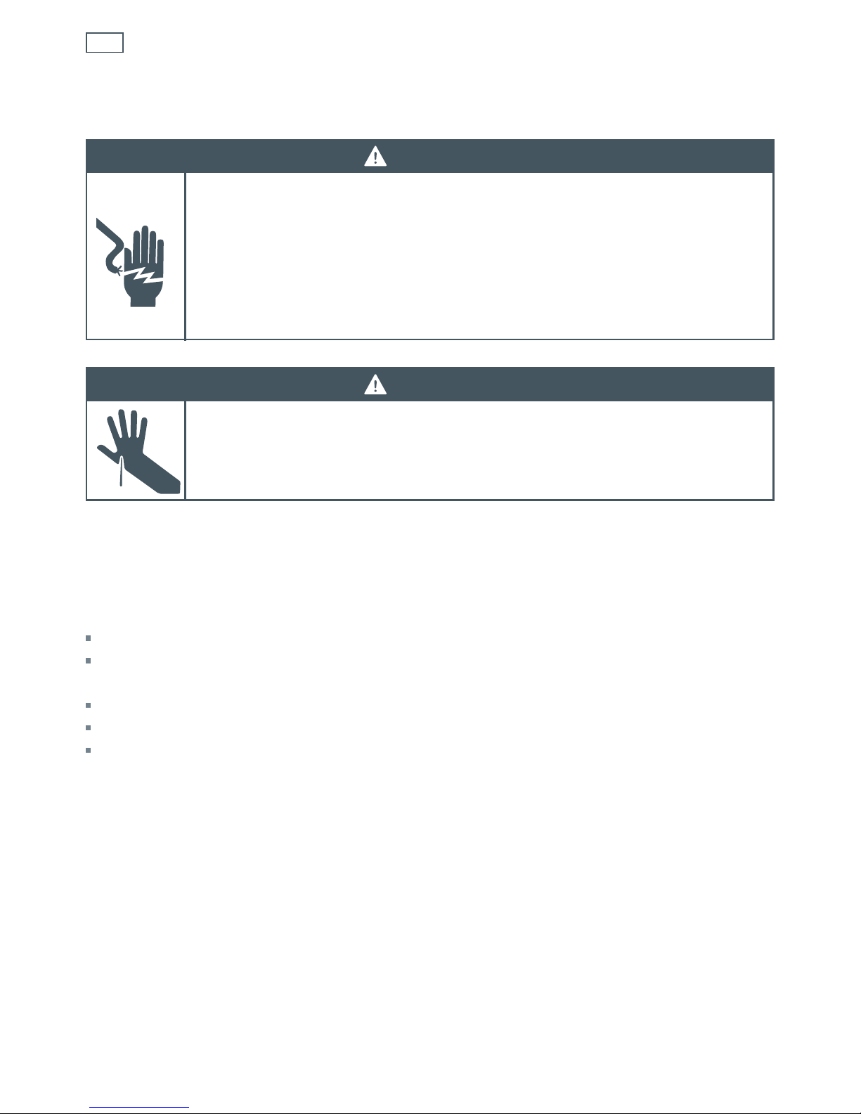
WARNING!
Electrical Shock Hazard
If the ceramic glass cooktop surface becomes cracked, switch the appliance
o at the mains power supply and call an Authorised Service Agent.
Always disconnect the cooker from the mains electricity supply before
carrying out any maintenance operations or repairs.
Failure to do so may result in death or electrical shock.
Installation
WARNING!
Cut Hazard
Take care - panel edges are sharp.
Failure to use caution could result in injury or cuts.

3
Safety and warnings
Electrical
This cooker is to be installed and connected to the electricity supply only by an authorised
person.
If the installation requires alterations to the domestic electrical system call, a qualified
electrician. The electrician should also check that the electrical system is suitable for the
electricity drawn by the cooker.
The appliance must be connected to the mains, checking that the voltage corresponds to the
value given in the rating plate and that the electrical cable sections can withstand the load
specified on the plate.
A suitable disconnection switch must be incorporated in the permanent wiring, mounted
and positioned to comply with the local wiring rules and regulations. The switch must
be of an approved type installed in the fixed wiring and provide a 3 mm air gap contact
separation in all poles in accordance with the local wiring rules.
The switch must always be accessible.
The power supply cable must not touch any hot parts and must be positioned so that it does
not exceed 75 °C at any point.
To connect the cooker to the mains, do not use adapters, reducers or branching devices as
they can cause overheating and burning.
This cooker must be connected to a suitable double pole control unit adjacent to the cooker.
No diversity can be applied to this control unit.
If the electrical supply cord is damaged, it must only be replaced by an authorised person.
The cooker must be earthed.

4
Safety and warnings
Operation
Your freestanding cooker has been carefully designed to operate safely during normal
cooking procedures. Please keep the following guidelines in mind when you are using it:
WARNING!
Explosion Hazard
Do not store ammable materials such as gasoline near the cooktop.
Do not store ammable material in the oven or storage compartment.
Do not spray aerosols near the cooktop during use.
Failure to follow this advice may result in death or serious injury.
WARNING!
Electrical Shock Hazard
Switch the power to the cooker o at the wall before replacing fuses or the
oven lamp.
If the cooktop surface is cracked, switch the appliance o at the wall. Contact
an accredited service provider to repair it, and do not use until it has been
repaired.
Failure to follow this advice may result in death or electrical shock.
WARNING!
Hot Surface Hazard
Accessible parts may become hot when this cooker is in use.
To avoid burns and scalds keep children away.
Do not touch the cooktop surface when the hot surface indicator lights are on.
Do not touch hot surfaces inside the oven.
Use oven mitts or other protection when handling hot surfaces such as oven
shelves or dishes.
Handles of saucepans may be hot to touch. Check saucepan handles do not
overhang other cooking zones that are on. Keep handles out of reach of
children.
Take care when opening the oven door.
Let hot air or steam escape before removing or replacing food.
Before cleaning, turn the cooker o and make sure it is cool.
Failure to follow this advice could result in burns and scalds.

5
Safety and warnings
Important safety precautions
Never leave the appliance unattended when in use. Boilover causes smoking and greasy
spillovers that may ignite.
Isolating switch: make sure this cooker is connected to a circuit which incorporates an
isolating switch providing full disconnection from the power supply.
Household appliances are not intended to be played with by children.
Children of less than 8 years old must be kept away from the appliance unless continuously
supervised. This appliance can be used by children aged from 8 years and above, and
persons with reduced physical, sensory or mental capabilities or lack of experience and
knowledge, if they have been given supervision or instruction concerning the use of the
appliance in a safe way and they understand the hazards involved. Cleaning and user
maintenance shall not be done by children without supervision.
Safe food handling: leave food in the oven for as short a time as possible before and after
cooking. This is to avoid contamination by organisms which may cause food poisoning. Take
particular care during warmer weather.
Do not place aluminium foil, dishes, trays, water or ice on the oven floor during cooking as
this will irreversibly damage the enamel.
Do not line the walls with aluminium foil.
Do not stand on the oven door or cooktop, or place heavy objects on them.
Do not use harsh abrasive cleaners or sharp metal scrapers to clean the ceramic glass
cooktop and the oven door glass since they scratch the surface, which may result in
shattering of the glass.
Some heavy-duty and nylon scourers can scratch the ceramic glass cooktop. Always read the
label to check if your scourer is suitable for cleaning ceramic glass cooktops.
Do not use a steam cleaner to clean any part of the cooker.
Do not use glassware on the ceramic glass cooktop. Do not use pans with rough circular
machined base as these may scratch the glass surface.
Do not place aluminium foil or plastic dishes on the ceramic glass cooktop.
Do not let large saucepans or frying pans overlap the bench as this can deflect heat onto
your benchtop and damage the surface.
Do not let large saucepans, frying pans or woks push any other pans aside. This could make
them unstable or deflect heat onto your benchtop and damage the surface.
Handles of saucepans may be hot to touch. Check saucepan handles do not overhang other
elements that are on. Keep handles out of reach of children.
If the electrical supply cord is damaged, it must only be replaced by an authorised person.
This cooker is not to be used as a space heater.
Do not drop heavy objects onto the cooktop.
6
Installation instructionsInstallation instructions
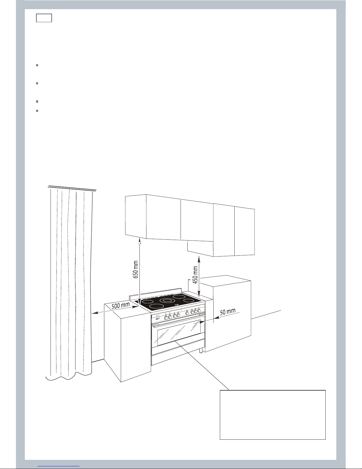
Cooker overall dimensions [mm]
•
height:
min 892 - max 917
•
product width: 898
•
depth: 600
•
cavity width 900
Fig. 1 Dimensions and
distances from cooker
Dimensions and clearances
The cooker must be installed no less than 50 mm away from any side walls which exceed the
height of the cooktop.
The cabinetry surrounding the cooker must be made of heat-resistant material and must be able
to withstand temperatures of 65 °C above room temperature.
Do not install the cooker near flammable materials (eg curtains).
If you stand the cooker on a pedestal, make sure you provide safety measures to keep it in place.
Installing the cooker above a plinth without fitting the adjustable feet
In that case the cooker stands directly above the plinth; make sure you provide safety measures
to keep it in place. Revise the installation dimensions accordingly considering that the feet have
the following measures: min 155 mm - max 180 mm.
7
Installation instructions
Fig. 4 Top of feet to be
screwed in tightly
256.5 - 281.5
mm (*)
(*) Depending on
feet adjustment
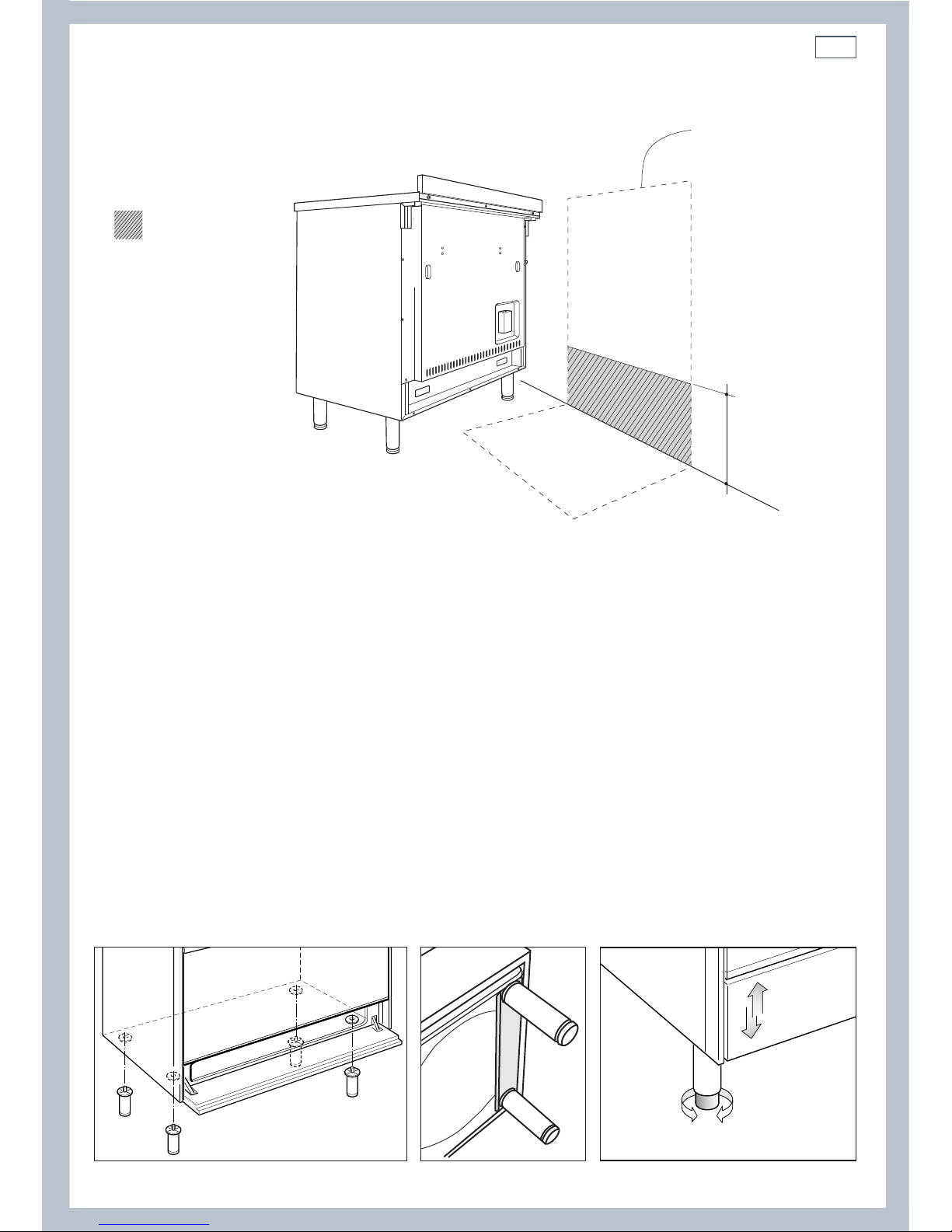
Fitting the adjustable feet
Important!
It is possible to install the cooker above a plinth without fitting the adjustable feet.
In that case the cooker will stand directly above the plint; make sure you provide safety measures to
keep it in place.
Fit the adjustable feet before using the cooker.
1
Rest the rear of the cooker on a piece of the polystyrene packaging, exposing the base for
fitting the feet.
2
Fit the four feet by screwing them tight into the support base as shown.
Levelling the cooker
Level the cooker by screwing the feet in or out,
as shown in Fig.5.
Fig. 3 Location of feet Fig. 5 Levelling the cooker
Locating the area for electrical connection
Dotted line showing
the position of the
cooker when installed
Area for electrical
connection
Fig. 2 Area for electrical connection
8
A
B
C
Installation instructionsInstallation instructions
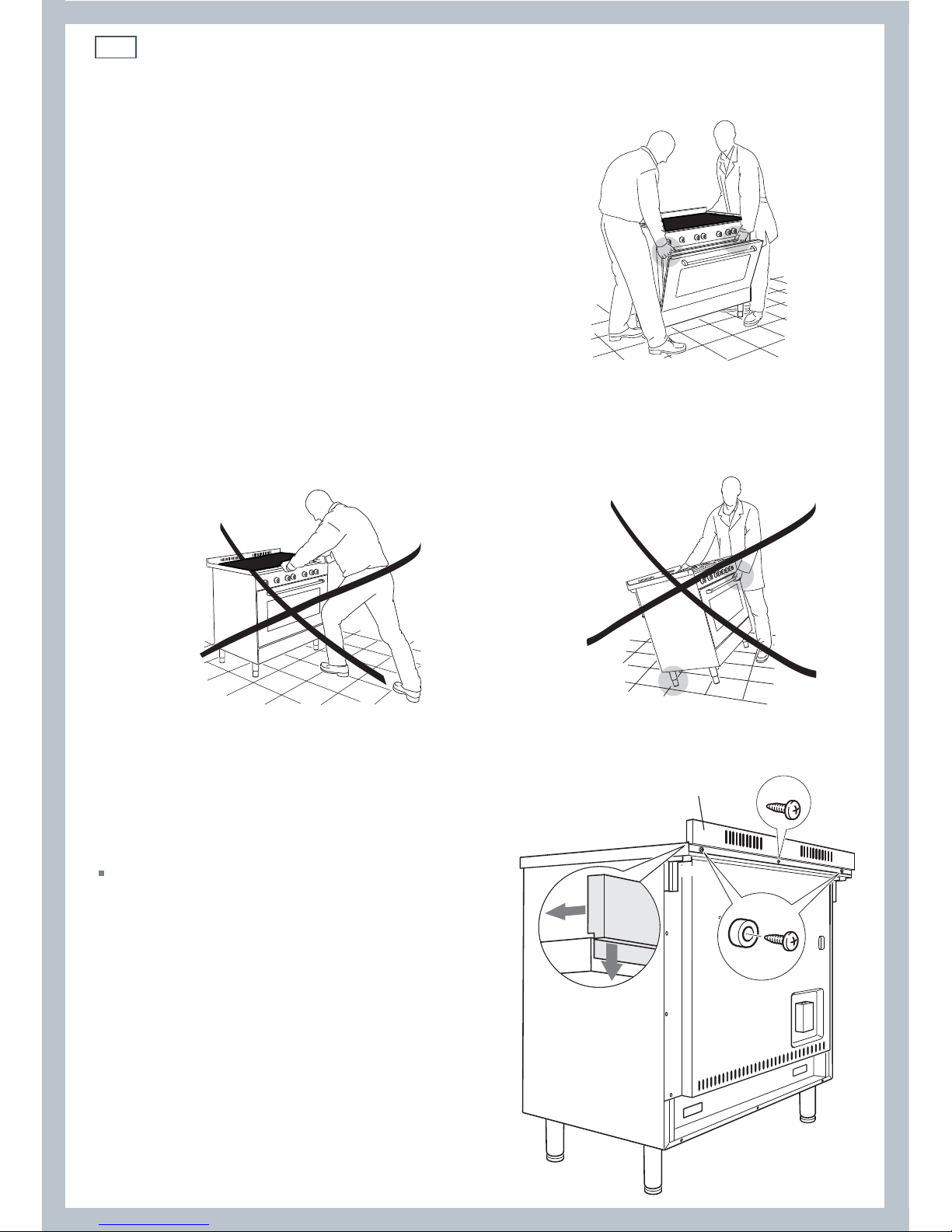
Important!
To prevent damaging the adjustable feet, ensure
the cooker is always lifted by two people.
Do not lift the cooker by the door handle.
DO NOT DRAG the cooker. Lift the feet clear of the
floor.
Moving the cooker
Fig. 6 Correctly lifting the cooker
Fig. 8 Incorrectly lifting the cookerFig. 7 Incorrectly moving the cooker
Fixing the backguard
Before installing the cooker, assemble the
backguard “C” .
The backguard “C” can be found packed
at the rear of the cooker.
1
Before assembling, remove any protective
film/adhesive tape.
2
Remove the two spacers “A” and the
screw “B” from the rear of the cooktop.
3
Assemble the backguard as shown and
fix it by screwing the central screw “B”
and the spacers “A”.
Fig. 9 Fixing
the backguard
9
Installation instructions
65
mm
833 mm
0
+ 25
min 210 mm
max 235 mm
(depending on feet adjustment)
898 mm (product width)
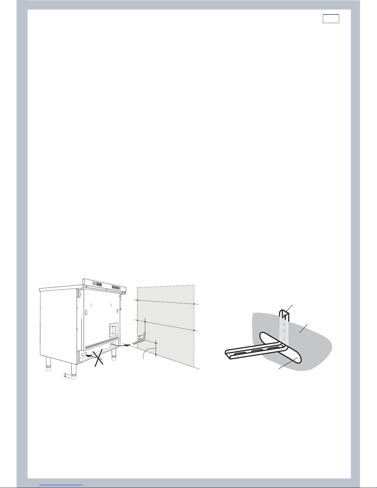
Fitting the anti-tilt bracket
Important!
To restrain the appliance and prevent it tipping accidentally, fit a bracket to its rear to fix it securely to the
wall.
If installing the cooker above a plinth (without fitting the adjustable feet), revise the installation dimensions
accordingly considering that the feet have the following measures: min 155 mm - max 180 mm.
To fit the anti-tilt bracket:
1
After you have located where the cooker is to be positioned, mark on the wall the place where
the two screws of the anti-tilt bracket have to be fitted. Please follow the indications given in
Fig10a.
2
Drill two 8 mm diameter holes in the wall and insert the plastic plugs supplied.
Important!
Before drilling the holes, check that you will not damage any pipes or electrical wires.
3
Loosely attach the anti-tilt bracket with the two screws supplied.
4
Move the cooker to the wall and adjust the height of the anti-tilt bracket so that it can engage in
the slot on the cooker’s back, as shown in Fig.10a.
5
Tighten the screws attaching the anti-tilt bracket.
6
Push the cooker against the wall so that the anti-tilt bracket is fully inserted in the slot on the
cooker’s back.
Fig. 10a Fitting the anti-tilt bracket Fig. 10b Fixing the anti-tilt bracket to the wall.
Anti-tilt bracket
attached on the
rear wall
Cooker’s
back
Slot on the
cooker’s back
10
Installation instructions
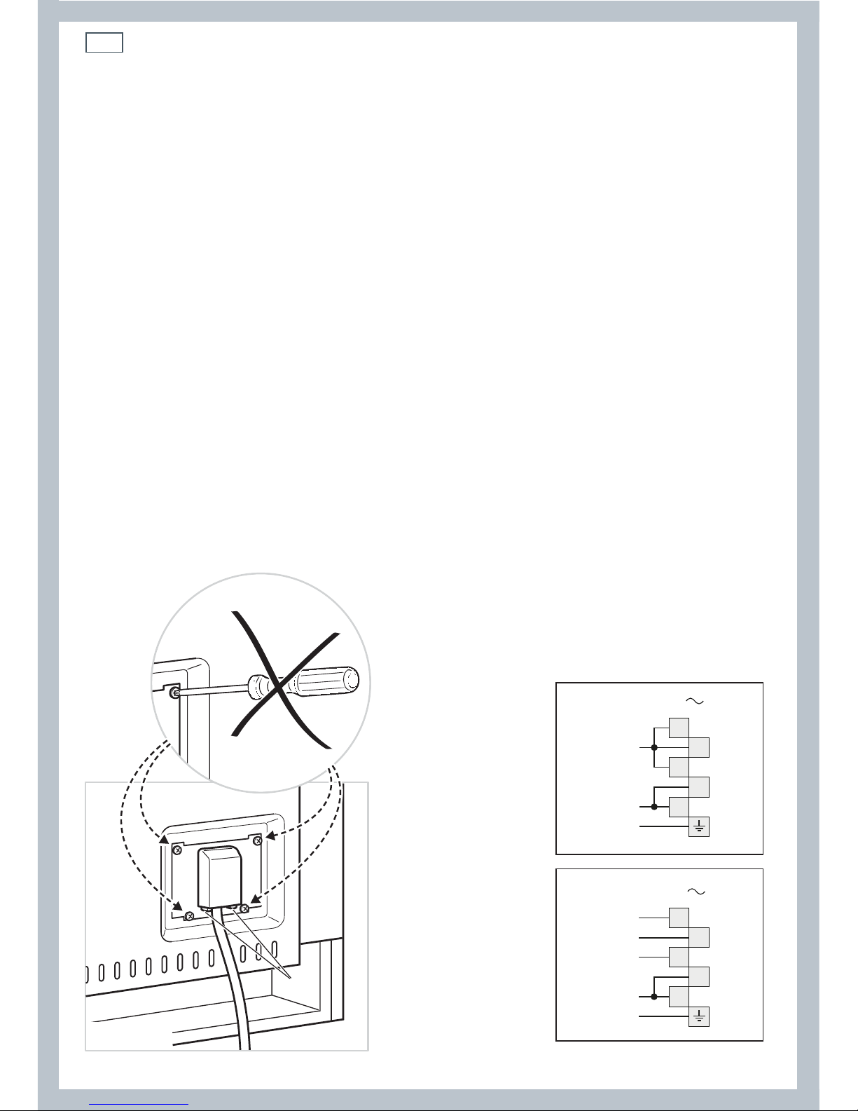
Connecting the power supply cable
Important!
This cooker must be connected to the electricity supply only by an authorised person.
To connect the power supply cable to the cooker, it is necessary to:
1
Unhook the terminal board cover by inserting a screwdriver into the two hooks ‘A’ (fig. 11).
2
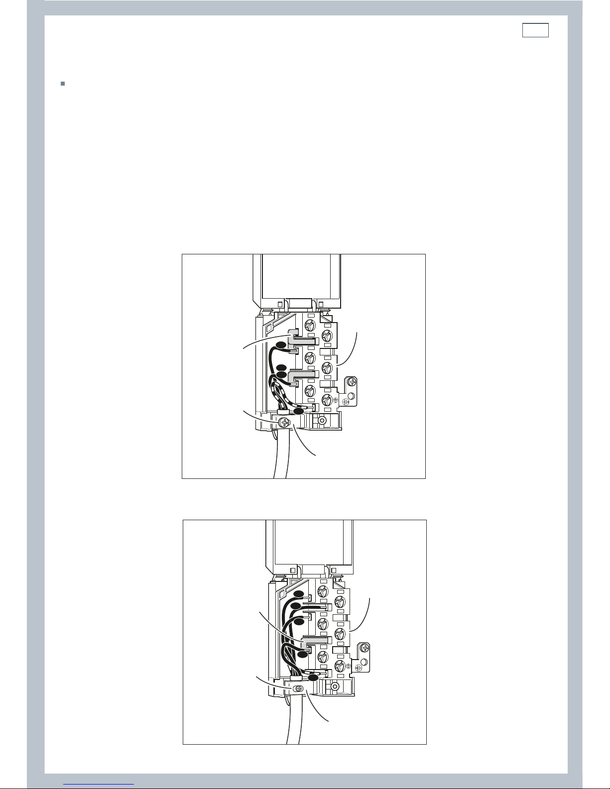
Unscrew the screw ‘D’ and open completely the cable clamp ‘E’ (figs. 12a).
3
Position the U bolts ‘F’ onto terminal board ‘G’ (figs. 12a) according to the diagrams in fig. 12.
4
Connect the phase, neutral and earth wires to terminal board ‘G’ according to the diagrams in
figs. 12 - 12a.
5
Strain the feeder cable and block it with cable clamp ‘E’ (by screwing screw ‘D’).
6
Close the terminal block cover (check the two hooks ‘A’ are correctly hooked).
Important!
To connect the power supply cable DO NOT unscrew the screws fixing the cover plate behind the terminal
block.
WARNING: If the power supply cable is damaged, it must be replaced only by an authorised service agent in
order to avoid a hazard.
Voltage and power consumption
220-240/380-415 V 3N~ 50/60 Hz 11880 W (diversity not applied)
A
PE
N (L2)
L
1
220-240 V
1
2
3
4
5
1
2
3
4
5
PE
380-415 V 3N
N
L1
L3
L2
Fig. 11 Terminal block Fig. 12 Connection diagrams
11
Installation instructions
Feeder cable section
This cooker must be connected to electrical supply using H05RR-F or H05VV-F insulated cable.
220-240 V~ 3 x 6 mm
2
(*)
380-415 V 3N~ 5 x 2,5 mm
2
(*)
* Connection with wall box connection.
- Diversity factor applied.
- A diversity factor may be applied to the total loading of the appliance only by a suitably
qualified person.
~
1
2
3
5
4
N
L2
PE
L1
G
F
D
E
220-240 V
1
2
3
5
4
PE
N
L1
L2
L3
G
F
D
E
~
380-415 V 3N
Fig. 12a Connection diagrams
12
TM
C
G
S
V
CIR
S1
LF
F1
N/7
1
1a
L/8
PR
1
6
1a
6a
4
9
4a
9a
3
8
3a
8a
2
7
2a
7a
5
10
11
5a
10a
11a
CF
TL
TMS
S2
42
5
31
M
T
S3
F2 F3 F4 F5 F6
S1
S2
4
4a
P1
P2
2
S1
S2
4
P1
P2
2
CR
P22P1
1
GIR
F7
P2P1
H
S2
4
H
S2
4
H
S2
4
H
S2
4
P4
P5
S1
S2
4
Pilot
P1
P2
2
S1
S2
4
P1
P2
2
Pilot Pilot
S1
S2
4
P1
P2
2
Pilot
P3
4A
HS
2
4
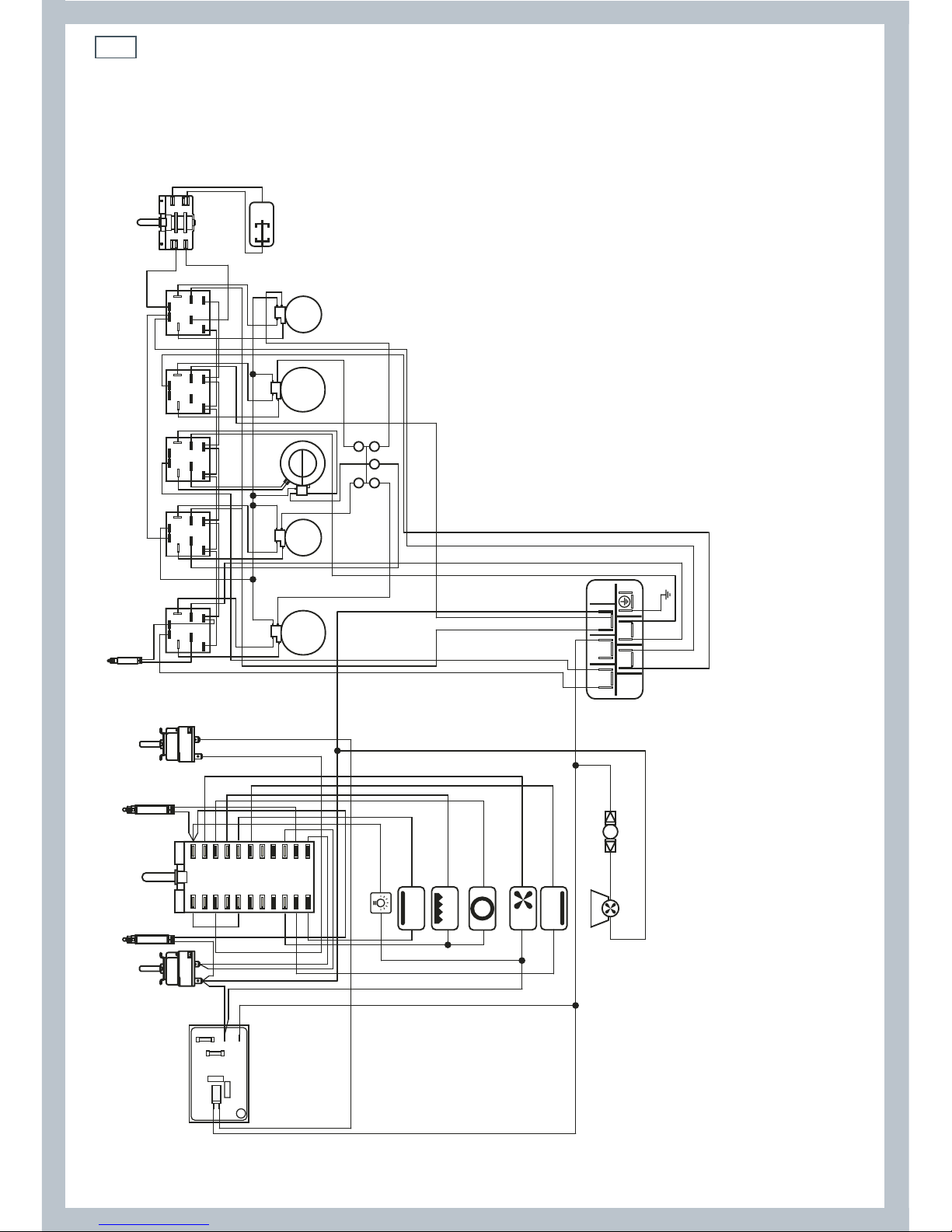
ELECTRIC DIAGRAM KEY
F1 Oven switch
F2/3/5/6 Radiant hotplate energy regulators
F4 Double hotplate energy regulator
F7 Rotisserie switch
TM Thermostat
LF Oven lamp
PR Oven programmer
CF Cooling fan
C Top element
G Grill element
V Fan motor
S Bottom element
CIR Circular element
P2/5 Radiant hotplates 1C 1200W
P1/4 Radiant hotplates 1C 1800W
P3 Double hotplate 2C 2100W
CR Residual heat lamps group
TL Thermal overload
TMS Safety thermostat
GIR Rotisserie
S1 Thermostat pilot lamp
S2 Line pilot lamp
S3 Hotplates line pilot lamp
M Terminal block
T Earth connection
Installation instructions
Wiring diagram

13
 Loading...