

Fisher & Paykel OR90SBDSIX Series, OR90SDBSIPX Installation Instructions And User Manual

NZ AU
Installation instructions
and User guide
Freestanding cooker
OR90SBDSIX models


1
Contents
Safety and warnings
2
Installation instructions
8
First use
16
Using your oven
19
Cooking functions
22
Cooking guide
25
Using the rotisserie
26
Using the electronic timer
28
Automatic cooking
29
Induction cooktop introduction
30
Choosing the right cookware
32
Using your induction cooktop
34
Using your cooktop’s special features
35
Cooking guidelines
37
Care and cleaning
38
Cooktop fault codes
52
Troubleshooting
52
Warranty and service
55
Important!
SAVE THESE INSTRUCTIONS
The models shown in this User Guide may not be available in all markets and are
subject to change at any time. For current details about model and specification
availability in your country, please go to our website www.fisherpaykel.com or
contact your local Fisher & Paykel dealer.
2
Safety and warnings
WARNING!
Electrical Shock Hazard
If the ceramic glass cooktop surface becomes cracked, switch the appliance
off at the mains power supply and call an Authorised Service Agent.
Always disconnect the cooker from the mains electricity supply before
carrying out any maintenance operations or repairs.
Failure to follow this advice may result in death or electrical shock.
Important safety instructions
General
To avoid hazard, follow these instructions carefully before installing or using this product.
Please make this information available to the person installing the product as it could reduce
your installation costs.
Installation must comply with your local building and electricity regulations.
Failure to install the cooker correctly could invalidate any warranty or liability claims.
Some appliances have a protective film. Remove this film before using the cooker.
Do not modify this appliance.
Do not operate your appliance by means of an external timer or separate remote-control system.
This appliance is to be installed and serviced only by an authorised person.
User servicing: do not repair or replace any part of the appliance unless specifically
recommended in the manual. All other servicing should be referred to a qualified technician.
Do not install or operate the appliance if it is damaged or not working properly. If you receive a
damaged product, contact your dealer or installer immediately.
Installation
WARNING!
Cut Hazard
Take care - panel edges are sharp.
Failure to use caution could result in injury or cuts.

3
Electrical
This cooker is to be installed and connected to the electricity supply only by an authorised person.
If the installation requires alterations to the domestic electrical system, call a qualified
electrician. The electrician should also check that the electrical system is suitable for the
electricity drawn by the cooker.
The appliance must be connected to the mains electricity supply, checking that the voltage
corresponds to the value given in the rating plate and that the electrical cable sections can
withstand the load specified on the plate.
A suitable disconnection switch must be incorporated in the permanent wiring, mounted and
positioned to comply with the local wiring rules and regulations. The switch must be of an
approved type installed in the fixed wiring and provide a 3 mm air gap contact separation in all
poles in accordance with the local wiring rules.
In Australia and New Zealand, a switch of the approved type with a 3 mm air gap must be
installed in the active (phase) conductor of the fixed wiring.
The switch must always be accessible.
The power supply cable must not touch any hot parts and must be positioned so that it does not
exceed 75
O
C at any point.
To connect the cooker to the mains electricity supply, do not use adapters, reducers or branching
devices as they can cause overheating and burning.
This cooker must be connected to a suitable double pole control unit adjacent to the cooker. No
diversity can be applied to this control unit.
If the electrical supply cord is damaged, it must only be replaced by an authorised person.
In Australia and New Zealand: this cooker must be connected to electrical supply using V105
insulated cable.
In New Zealand, this appliance must be connected to the electrical supply using a cable fitted
with an appropriately rated plug. The plug must be compatible with the socket-outlet fitted to the
final subcircuit in the fixed wiring that is intended to supply the appliance.
In United Kingdom and Ireland: this cooker must be connected to electrical supply using H05RR-F
or H05VV-F insulated cable.
The cooker must be earthed.
OR90SDBSIX2 220-240/380-415 V 3N~, 11080 W (*), 50/60 Hz 48,17 A (230 V) (*)
(*) diversity not applied
Safety and warnings
4
Operation
Your freestanding cooker has been carefully designed to operate safely during normal cooking
procedures. Please keep the following guidelines in mind when you are using it:
Safety and warnings
WARNING!
Electrical Shock Hazard
Switch the cooker off at the wall before replacing fuses or the oven lamp.
If the cooktop surface is cracked, switch the appliance off at the wall. Contact an
accredited
service provider to repair it, and do not use until it has been repaired.
Failure to do so may result in death or electrical shock.
WARNING!
Explosion Hazard
Do not store flammable materials such as gasoline near the cooktop.
Do not store flammable material in the oven or storage compartment.
Do not spray aerosols near the cooktop during use.
Failure to follow this advice may result in death or serious injury.
5
Safety and warnings
WARNING!
Health Hazard
This appliance complies with electromagnetic safety standards.
However, persons with cardiac pacemakers or other electrical implants (such as
insulin pumps) must consult with their doctor or implant manufacturer before
using this appliance to make sure that their implants will not be affected by the
electromagnetic field.
Failure to follow this advice may result in death.
WARNING!
Hot Surface Hazard
Accessible parts may become hot when this cooker is in use.
To avoid burns and scalds keep children away.
Do not let body, clothing or any item other than suitable cookware contact with
the ceramic glass until the surface is cool.
Never leave metal objects (such as kitchen utensils) or empty pans on the
cooktop as they can become hot very quickly.
Beware: magnetisable metal objects worn on the body may become hot in the
vicinity of the cooktop. Gold or silver jewellery will not be affected.
Keep children away.
Handles of saucepans may be hot to touch. Check saucepan handles do not
overhang other cooking zones that are on. Keep handles out of reach of children.
Do not touch hot surfaces inside the oven.
Use oven mitts or other protection when handling hot surfaces such as oven
shelves or dishes.
Take care when opening the oven door.
Let hot air or steam escape before removing or replacing food.
Do not touch the cooktop components, burners, trivets/pan supports or the base
when hot.
Before cleaning, turn the cooker off and make sure it is cool.
Failure to follow this advice could result in burns and scalds.

6
Safety and warnings
Important safety instructions
Never leave the appliance unattended when in use. Boilover causes smoking and greasy
spillovers may ignite.
NEVER try to extinguish a fire with water, but switch off the appliance and then cover flame eg
with a lid or a fire blanket.
WARNING: Danger of fire: do not store items on the cooking surfaces. Do not use your cooktop as
a work surface.
Do not use a steam cleaner on any part of your cooker.
Isolating switch: make sure this cooker is connected to a circuit which incorporates an isolating
switch providing full disconnection form the power supply.
Household appliances are not intended to be played with by children. Do not store things
children might want above the oven. Children could be burned or injured while climbing on the
oven to retrieve items.
Children of less than 8 years old must be kept away from the appliance unless continuously
supervised. This appliance can be used by children aged from 8 years and above, and persons
with reduced physical, sensory or mental capabilities or lack of experience and knowledge, if
they have been given supervision or instruction concerning the use of the appliance in a safe way
and they understand the hazards involved. Cleaning and user maintenance shall not be done by
children without supervision.
Safe food handling: leave food in the oven for as short a time as possible before and after
cooking. This is to avoid contamination by organisms which may cause food poisoning. Take
particular care during warmer weather.
If the electrical supply cord is damaged, it must only be replaced by an authorised person.
This cooker is not to be used as a space heater, especially if it is installed in marine craft or in a
caravan.
Operation
Do not place aluminium foil, dishes, trays, water or ice on the oven floor during cooking as this
will irreversibly damage the enamel.
Do not line the walls with aluminium foil. Do not stand on the door, or place heavy objects on it.
Do not place or leave any magnetisable objects (eg credit cards, memory cards) or electronic
devices (eg computers, MP3 players) near the appliance, as they may be affected by its
electromagnetic field.
We recommend using plastic or wooden kitchen utensils for cooking with your induction cooktop.
After use, always turn off the cooking zones. Do not rely on the pan detection feature to turn off
the cooking zones when you remove the pans.
Do not place or drop heavy objects on your cooktop.
Do not stand on your cooktop. Do not use pans with jagged edges or drag pans across the
ceramic glass surface as this can scratch the glass.

7
Safety and warnings
Important safety instructions
Do not use harsh abrasive cleaners or sharp metal scrapers to clean the ceramic glass cooktop
and the oven door glass since they scratch the surface, which may result in shattering of the
glass. Some heavy-duty and nylon scourers can scratch the ceramic glass cooktop. Always read
the label to check if your scourer is suitable for cleaning ceramic glass cooktops.
Do not use pans with rough circular base as these may scratch your cooktop.
Wear proper apparel. Do not wear loose fitting or hanging garments when using the appliance.
They could ignite or melt if they touch an element or hot surface and you could be burned.
Always keep oven vents unobstructed
Use only dry oven mitts or potholders. Moist or damp potholders on hot surfaces could result in
burns from steam. Do not let potholders touch hot areas or heating elements. Do not use a towel
or a bulky cloth for a potholder. It could catch fire.
Caution. Hot air can blow from the vent at the top of the oven as part of the oven’s cooling
system.
Placement of oven shelves: always position shelves in the desired location while the oven is cool
(before preheating). If a shelf must be removed while the oven is hot, do not let the oven mitts or
potholder contact hot heating elements in the oven or the base of the oven.
8
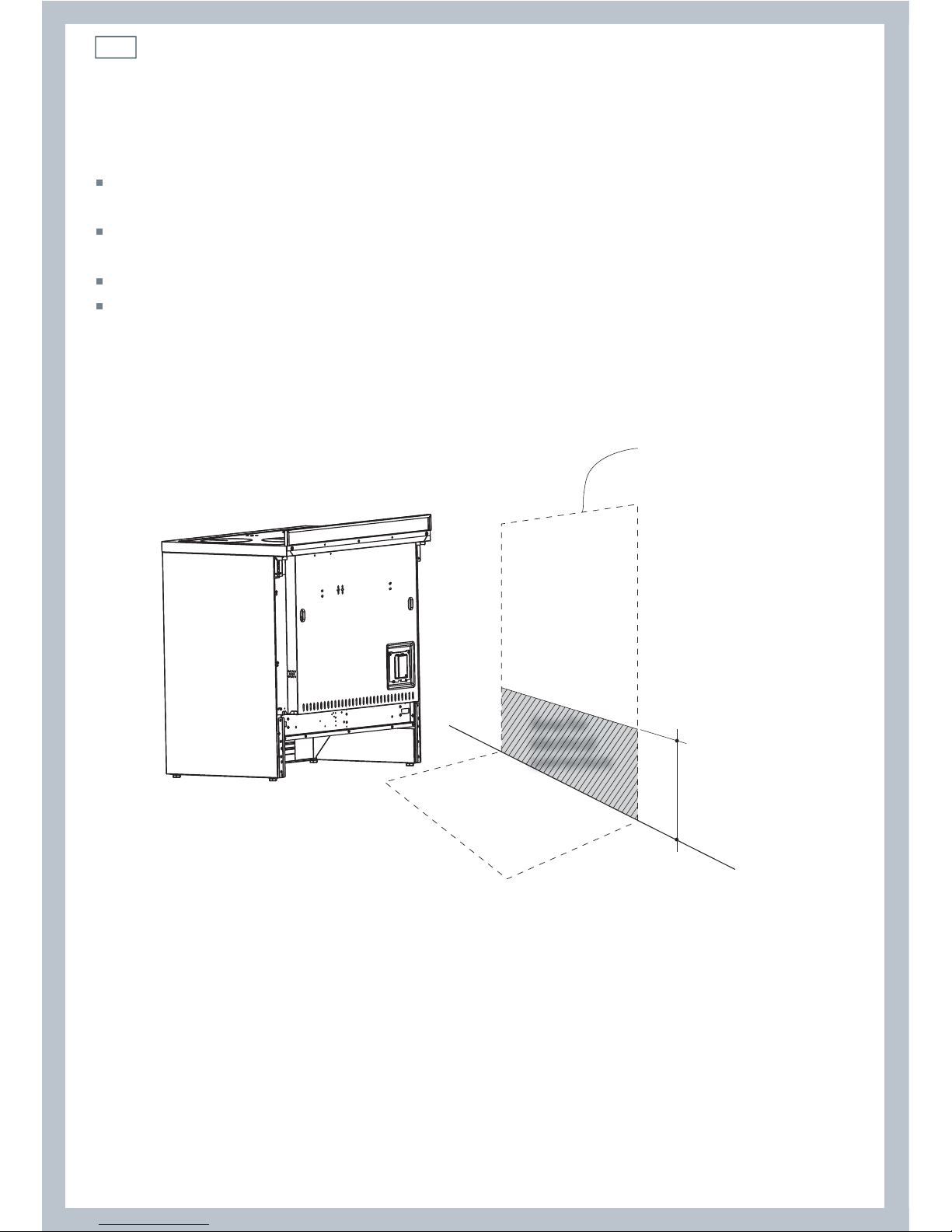
Dimensions and clearances
The cooker must be installed no less than 50 mm away from any side walls which exceed the
height of the cooktop.
The cabinetry surrounding the cooker must be made of heat-resistant material and must be able
to withstand temperatures of 65 °C above room temperature.
Do not install the cooker near flammable materials (eg curtains).
If you stand the cooker on a pedestal, make sure you provide safety measures to keep it in place.
Locating the area for electrical connection
Fig. 1 Area for electrical connection
Installation instructionsInstallation instructions
240 mm (*)
(*) Depending on
feet adjustment
Dotted line showing
the position of the
cooker when installed
Area for
electrical
connection
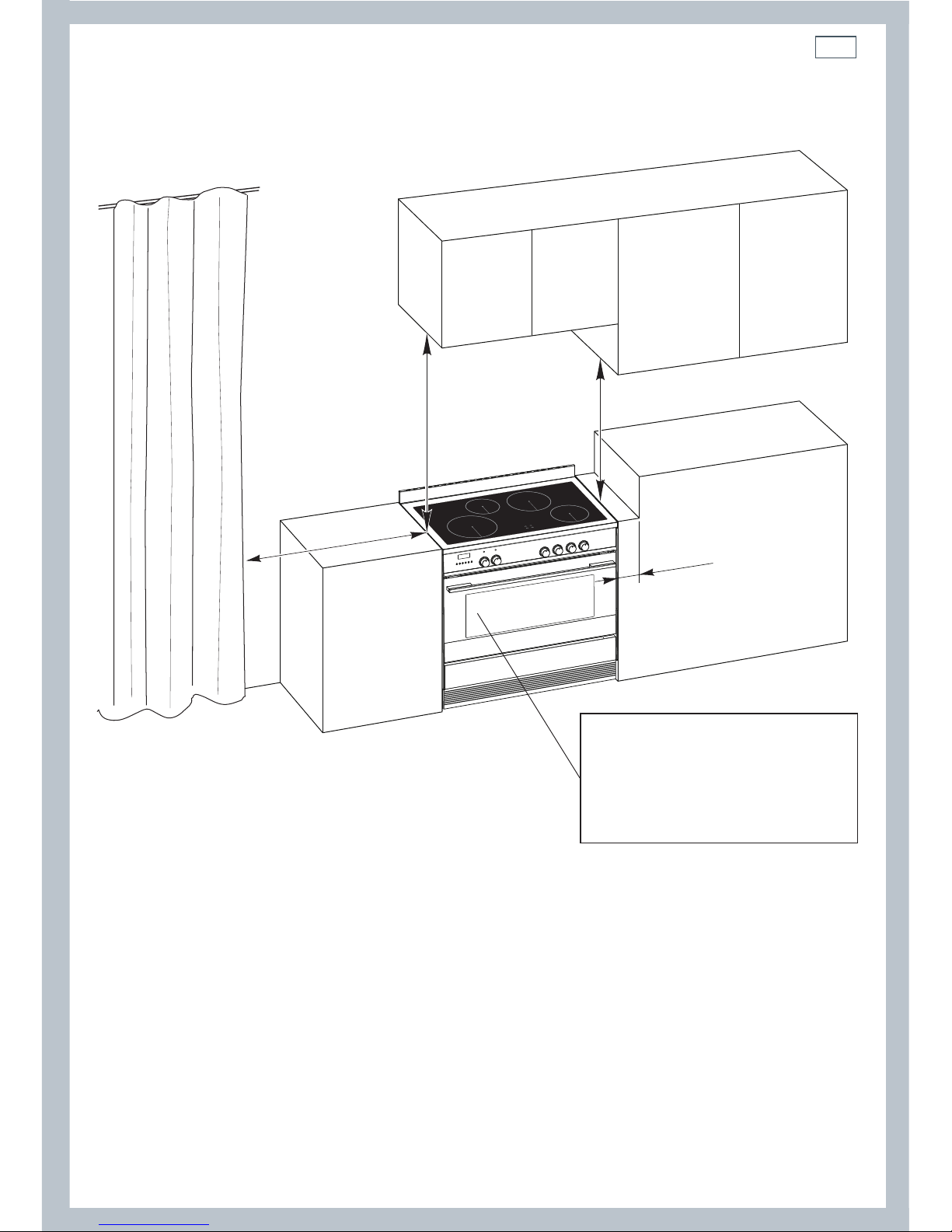
9
50 mm
650 mm
500 mm
450 mm
Cooker overall dimensions [mm]
•
height:
min 897 - max 910
•
product width: 897
•
depth: 600
•
cavity width 900
Fig. 2 Dimensions and
distances from cooker
Installation instructions
10
Installation instructionsInstallation instructions
+ 8
0
mm
+ 8
mm
+ 13
mm
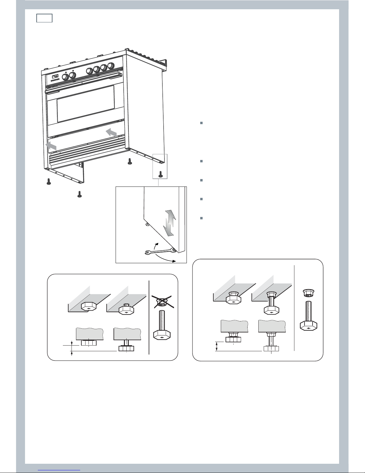
Levelling the cooker
Important!
Using the supplied adjustable feet is
MANDATORY. For safety reasons and to
ensure adequate ventilation, the cooker
chassis MUST NOT sit directly on the floor, a
plinth, or other support surface.
For ease of installation, first remove
the kickstrip. To remove the kickstrip,
unscrew the two screws holding it in
place.
The cooker is already fitted with four
levelling feet.
Level the cooker by screwing or
unscrewing the feet.
Make sure you follow the instructions in
Figs. 3a, 3b, and 3c.
Note: nuts are supplied with the cooker
in a separate kit.
Do not refit the kickstrip until you have
installed the anti-tip bracket.
Fig. 3b Do not use the supplied nuts for height
adjustments between 0 and 8 mm
Fig. 3c Use the supplied nuts for
height adjustments between 8 and 13 mm
Fig. 3a Screw/unscrew the
feet to get the required height
11
Installation instructions
Dotted line showing the position
of the cooker when installed
Rear left
foot of cooker
Anti-tilt
bracket
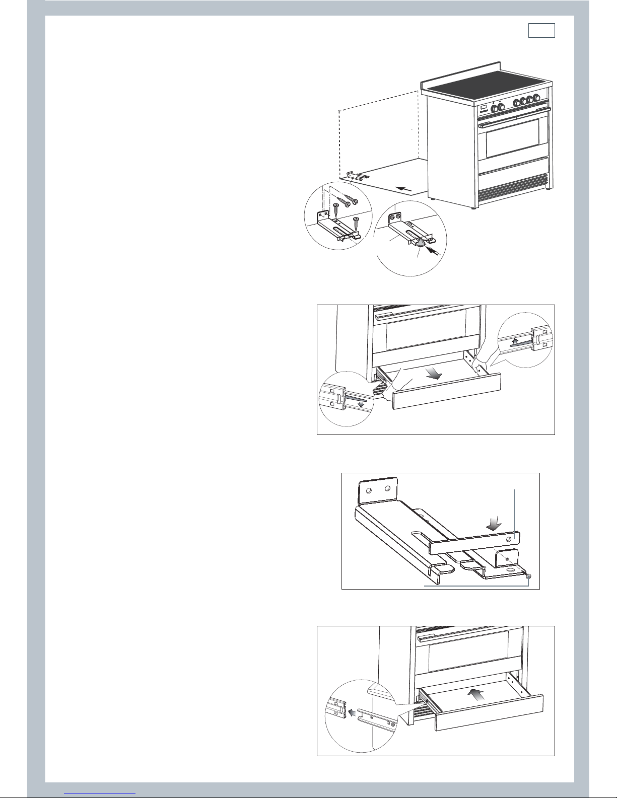
Fitting the anti-tilt bracket
Important!
To restrain the appliance and prevent
it tipping accidentally, the antitilt bracket and restraining plate
supplied must be fitted according to
the instructions below.
1
Drill four 8mm diameter holes for
the fixing screws (two in the wall
and two in the floor-see Fig.4) and
insert the plastic plugs supplied.
Important!
Before drilling the holes, check that you will not
damage any pipes or electrical wires.
2
Attach the anti-tilt bracket to the floor and
rear wall using the four screws supplied, as
shown in Fig. 4.
3
After attaching the anti-tilt bracket securely,
slide the cooker into place. Ensure that the
left rear foot slides under the bracket, as
shown in Fig.4.
4
Access the bracket by removing the drawer
(Fig. 5):
a
Slide out the drawer completely.
b
Press the lever of the left guide rail
down and pull the lever of the right
guide rail up.
c
Holding the levers, disengage and
remove the drawer.
5
If fitted, remove the kickstrip (see ‘Levelling
the cooker’). Fix the restraining plate by
sliding it into place and securing it with the
fixing screw and washer supplied. See Fig. 6.
6
Replace the drawer (Fig. 7):
a
Insert the drawer rails into the guide
rails.
b
Gently push the drawer in
completely; the safety catches will
automatically hook.
7
Replace the kickstrip using the two screws.
Important!
Beware of sharp edges when removing or
replacing the drawer.
Fig. 4 Attaching the
anti-tilt bracket and
sliding the cooker
into place
Fig. 5 Accessing the anti-tilt bracket
by removing the drawer
Fig. 7 Replacing the drawer
Fig. 6 Fixing the restraining plate
Restraining plate
Screw & Washer
12
Installation instructionsInstallation instructions
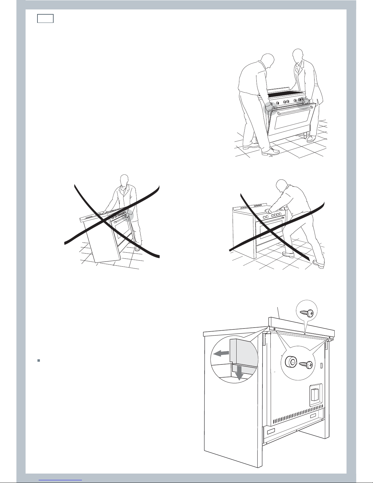
Important!
To prevent damaging the adjustable feet or lower
trim, ensure the cooker is always lifted by two
people.
Do not lift the cooker by the door handles.
DO NOT DRAG the cooker. Lift the feet clear of the
floor.
Moving the cooker
Fig. 8 Correctly lifting the cooker
Fig. 10 Incorrectly moving the cookerFig. 9 Incorrectly lifting the cooker
Fixing the backguard
Before installing the cooker, assemble the
backguard “C” .
The backguard “C” can be found packed
at the rear of the cooker.
1
Before assembling, remove any protective
film/adhesive tape.
2
Remove the two spacers “A” and the
screw “B” from the rear of the cooktop.
3
Assemble the backguard as shown and
fix it by screwing the central screw “B”
and the spacers “A”.
Fig. 11 Assembling
the backguard
A
B
C
13
Installation instructions
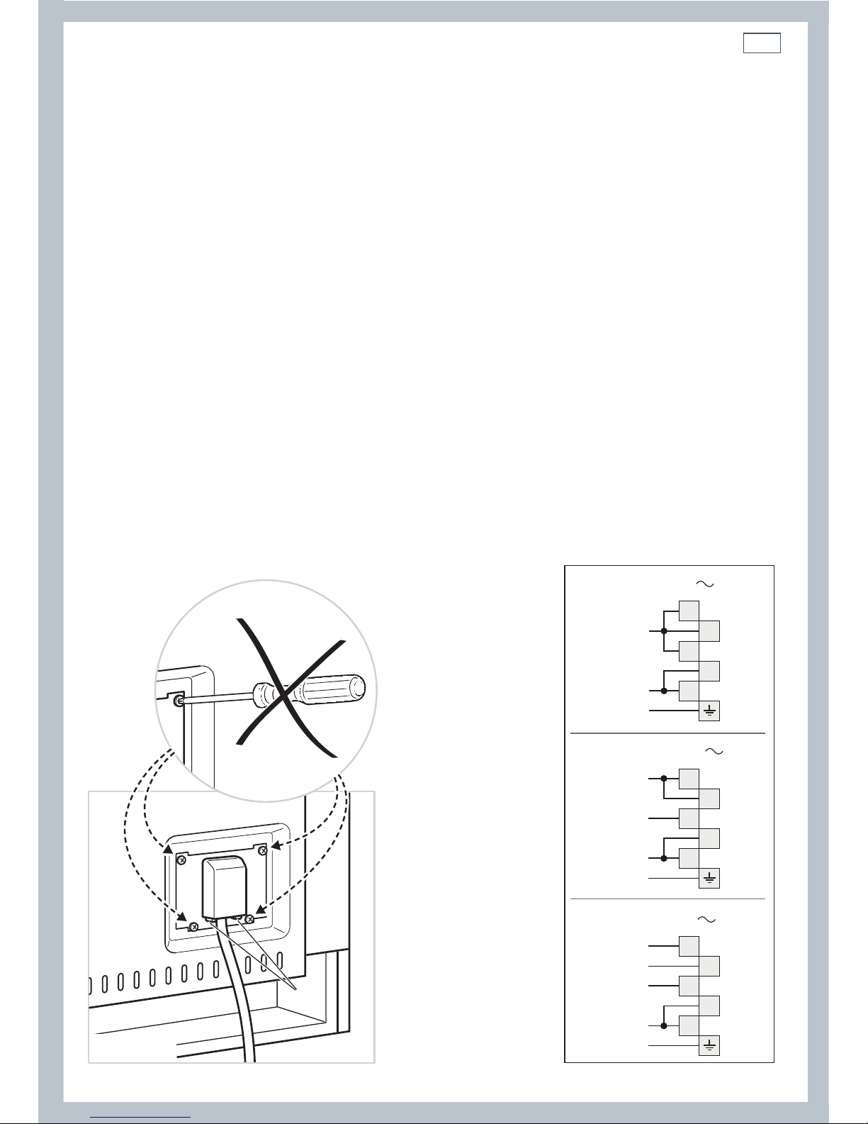
Connecting the power supply cable
Important!
This cooker must be connected to the electricity supply only by an authorised person.
To connect the power supply cable to the cooker, it is necessary to:
1 Unhook the terminal board cover by inserting a screwdriver into the two hooks ‘A’ (fig. 12).
2 Unscrew the screw ‘D’ and open completely the cable clamp ‘E’ (figs. 14).
3 Position the U bolts ‘F’ onto terminal board ‘G’ (figs. 14) according to the diagrams in fig. 13.
4 Connect the phase, neutral and earth wires to terminal board ‘G’ according to the diagrams in
figs. 13 - 14.
5 Strain the feeder cable and block it with cable clamp ‘E’ (by screwing screw ‘D’).
6 Close the terminal block cover (check the two hooks ‘A’ are correctly hooked).
Important!
To connect the power supply cable DO NOT unscrew the screws fixing the cover plate behind the terminal
block.
WARNING: If the power supply cable is damaged, it must be replaced only by an authorised service agent in
order to avoid a hazard.
Voltage and power consumption
220-240/380-415 V 3N~ 50/60 Hz 48,17 A (230 V) 11080 W (diversity not applied)
A
PE
N (L2)
L
1
220-240 V
1
2
3
4
5
1
2
3
4
5
PE
380-415 V 2N
N
L1
L2
1
2
3
4
5
PE
380-415 V 3N
N
L1
L3
L2
Fig. 12 Terminal block Fig. 13 Connection diagrams
14
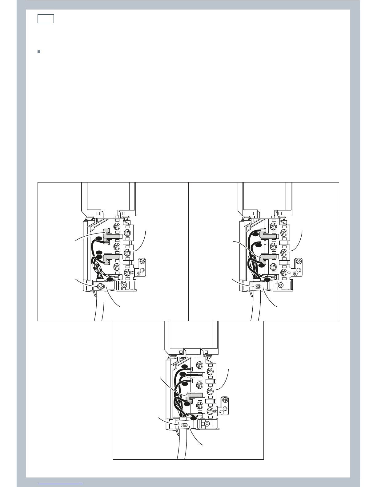
Installation instructions
Feeder cable section
In Australia and New Zealand: this cooker must be connected to electrical supply using V105
insulated cable.
220-240 V~ 3 x 6 mm
2
(*)
380-415 V 3N~ 5 x 2,5 mm
2
(*)
380-415 V 2N~ 4 x 6 mm
2
(*)
* Connection with wall box connection.
- Diversity factor applied.
- A diversity factor may be applied to the total loading of the appliance only by a suitably
qualified person.
~
1
2
3
5
4
N
L2
PE
L1
G
F
D
E
220-240 V
1
2
3
5
4
PE
N
L1
L2
G
F
D
E
~
380-415 V 2N
1
2
3
5
4
PE
N
L1
L2
L3
G
F
D
E
~
380-415 V 3N
Fig. 14 Connection diagrams
15
Installation instructions
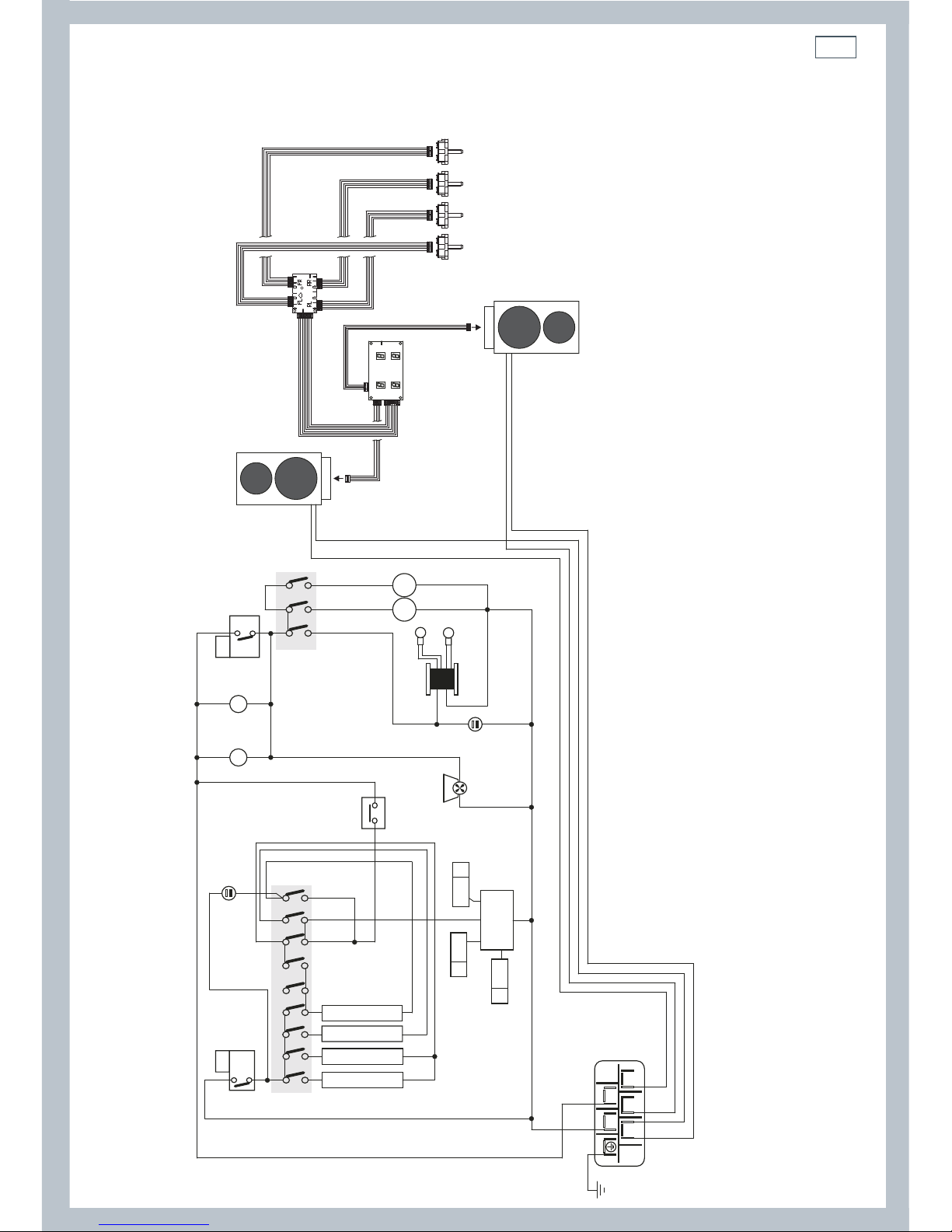
Wiring diagram
ELECTRIC DIAGRAM KEY
F1 Oven switch
ST Safety thermostat
TL Thermal overload
TL1 Induction hob thermal overload
PR Electronic programmer
PB Temperature probe
TS Oven temperature selector
EC Oven function selector (encoder)
R1 Relay 1
R2 Relay 2
LF Oven lamp
TR Oven lamps transformer
S1 Thermostat pilot lamp
S2 Line pilot lamp
C Oven top heating element
G Oven grill heating element
S Oven bottom heating element
CI Oven circular heating element
IU-LH Induction unit, left zones
IU-RH Induction unit, right zones
UD Induction units user display
PCB Induction units PCB
RSI Rotary selector interface
GIR Rotisserie motor
V Oven fan motor
CF Cooling fan motor
M Terminal block
T Earth connection
R1
R2
PT1
PT2
P8
P9
3a
3
4a
4
5a
5
6a
6
7a
7
GSCI C
8a
8
9a
9
10a
10
11a
11
1a
1
2a
2
LF
V
GIR
LF
TR
ST
12a
12
X1
TL TL1
PR
PR
PR
TS
EC
P4
PB
X0
F1
F1
IU-LH
IU-RH
RSI RSI RSI RSI
UD
PCB
CF
S1
S2
42
135
M
T
N
L1
N
L1
X6/X18/X19
X6/X18/X19
X1
X2
X8
16
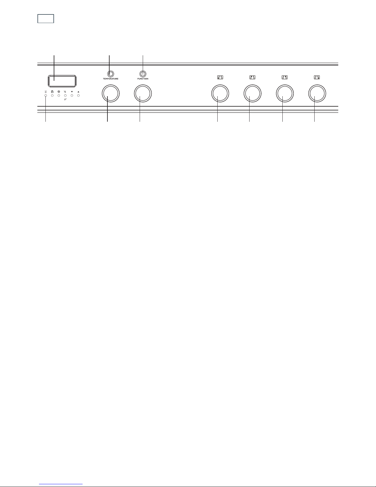
Fig. 15 Control panel
1
Control buttons
2
Clock display
3
Temperature dial
4
Function dial
5
Front left cooking zone dial
6
Rear left cooking zone dial
7
Rear right cooking zone dial
8
Front right cooking zone dial
9
Function indicator light
10
Temperature indicator light
2910
134 5678
First use
 Loading...