

Fisher & Paykel OR90SDBSI Installation Instructions And User Manual

NZ AU GB IE
Installation instructions
and User guide
Freestanding cooker
OR90SDBSI models


1
Contents
Safety and warnings
2
Installation instructions
6
Using your oven for the first time
14
Setting the clock
15
Using your oven
16
Cooking functions
17
Using the rotisserie
19
Using the electronic timer
20
Automatic cooking
21
Induction cooktop introduction
22
Choosing the right cookware
24
Using your induction cooktop
26
Using your cooktop’s special features
27
Cooking guidelines
29
Care and cleaning
30
Cooktop fault codes
43
Cooktop troubleshooting
44
Warranty and service
45
Important!
SAVE THESE INSTRUCTIONS
The models shown in this User Guide may not be available in all markets and are
subject to change at any time. For current details about model and specification
availability in your country, please go to our website www.fisherpaykel.com or
contact your local Fisher & Paykel dealer.
2
Safety and warnings
WARNING!
Electrical Shock Hazard
If the ceramic glass cooktop surface becomes cracked, switch the appliance
off at the mains power supply and call an Authorised Service Agent.
Always disconnect the cooker from the mains electricity supply before
carrying out any maintenance operations or repairs.
Failure to follow this advice may result in death or electrical shock.
Important safety instructions
General
To avoid hazard, follow these instructions carefully before installing or using this product.
Please make this information available to the person installing the product as it could reduce
your installation costs.
Installation must comply with your local building and electricity regulations.
Failure to install the cooker correctly could invalidate any warranty or liability claims.
Some appliances have a protective film. Remove this film before using the cooker.
Do not modify this appliance.
Do not operate your appliance by means of an external timer or separate remote-control system.
This appliance is to be installed and serviced only by an authorised person.
Installation
WARNING!
Cut Hazard
Take care - panel edges are sharp.
Failure to use caution could result in injury or cuts.

3
Electrical
This cooker is to be installed and connected to the electricity supply only by an authorised person.
If the installation requires alterations to the domestic electrical system, call a qualified
electrician. The electrician should also check that the electrical system is suitable for the
electricity drawn by the cooker.
The appliance must be connected to the mains electricity supply, checking that the voltage
corresponds to the value given in the rating plate and that the electrical cable sections can
withstand the load specified on the plate.
A suitable disconnection switch must be incorporated in the permanent wiring, mounted and
positioned to comply with the local wiring rules and regulations. The switch must be of an
approved type installed in the fixed wiring and provide a 3 mm air gap contact separation in all
poles in accordance with the local wiring rules.
In Australia and New Zealand, a switch of the approved type with a 3 mm air gap must be
installed in the active (phase) conductor of the fixed wiring.
The switch must always be accessible.
The power supply cable must not touch any hot parts and must be positioned so that it does not
exceed 75
O
C at any point.
To connect the cooker to the mains electricity supply, do not use adapters, reducers or branching
devices as they can cause overheating and burning.
This cooker must be connected to a suitable double pole control unit adjacent to the cooker. No
diversity can be applied to this control unit.
If the electrical supply cord is damaged, it must only be replaced by an authorised person.
In Australia and New Zealand: this cooker must be connected to electrical supply using V105
insulated cable.
In New Zealand, this appliance must be connected to the electrical supply using a cable fitted
with an appropriately rated plug. The plug must be compatible with the socket-outlet fitted to the
final subcircuit in the fixed wiring that is intended to supply the appliance.
In United Kingdom and Ireland: this cooker must be connected to electrical supply using H05RR-F
or H05VV-F insulated cable.
The cooker must be earthed.
Safety and warnings

4
Operation
Your freestanding cooker has been carefully designed to operate safely during normal cooking
procedures. Please keep the following guidelines in mind when you are using it:
Safety and warnings
WARNING!
Electrical Shock Hazard
Switch the cooker off at the wall before replacing fuses or the oven lamp.
If the cooktop surface is cracked, switch the appliance off at the wall. Contact an accredited
service provider to repair it, and do not use until it has been repaired.
Failure to do so may result in death or electrical shock.
WARNING!
Health Hazard
This appliance complies with electromagnetic safety standards.
However, persons with cardiac pacemakers or other electrical implants (such as insulin
pumps) must consult with their doctor or implant manufacturer before using this appliance
to make sure that their implants will not be affected by the electromagnetic field.
Failure to follow this advice may result in death.
WARNING!
Explosion Hazard
Do not store flammable materials such as gasoline near the cooktop.
Do not store flammable material in the oven or storage compartment.
Do not spray aerosols near the cooktop during use.
Failure to follow this advice may result in death or serious injury.
WARNING!
Hot Surface Hazard
Accessible parts may become hot when this cooker is in use.
To avoid burns and scalds keep children away.
Do not let body, clothing or any item other than suitable cookware contact with the
ceramic glass until the surface is cool.
Never leave metal objects (such as kitchen utensils) or empty pans on the cooktop as they
can become hot very quickly.
Beware: magnetisable metal objects worn on the body may become hot in the vicinity of
the cooktop. Gold or silver jewellery will not be affected.
Keep children away.
Handles of saucepans may be hot to touch. Check saucepan handles do not overhang
other cooking zones that are on. Keep handles out of reach of children.
Do not touch hot surfaces inside the oven.
Use oven mitts or other protection when handling hot surfaces such as oven shelves or
dishes.
Take care when opening the oven door.
Let hot air or steam escape before removing or replacing food.
Do not touch the cooktop components, burners, trivets/pan supports or the base when
hot.
Before cleaning, turn the cooker off and make sure it is cool.
Failure to follow this advice could result in burns and scalds.

5
Safety and warnings
Important safety instructions
Never leave the appliance unattended when in use. Boilover causes smoking and greasy
spillovers that may ignite.
Isolating switch: make sure this cooker is connected to a circuit which incorporates an isolating
switch providing full disconnection from the power supply.
Household appliances are not intended to be played with by children.
Children, or persons with a disability which limits their ability to use the appliance, should have a
responsible person to instruct them in its use. The instructor should be satisfied that they can use
the appliance without danger to themselves or their surroundings.
Safe food handling: leave food in the oven for as short a time as possible before and after
cooking. This is to avoid contamination by organisms which may cause food poisoning. Take
particular care during warmer weather.
Do not place aluminium foil, dishes, trays, water or ice on the oven floor during cooking as this
will irreversibly damage the enamel.
Do not line the walls with aluminium foil.
Do not stand on the door, or place heavy objects on it.
Do not place or leave any magnetisable objects (eg credit cards, memory cards) or electronic
devices (eg computers, MP3 players) near the appliance, as they may be affected by its
electromagnetic field.
We recommend using plastic or wooden kitchen utensils for cooking with your induction cooktop.
After use, always turn off the cooking zones. Do not rely on the pan detection feature to turn off
the cooking zones when you remove the pans.
Do not place or drop heavy objects on your cooktop.
Do not stand on your cooktop.
Do not use pans with jagged edges or drag pans across the ceramic glass surface as this can
scratch the glass.
Do not use harsh abrasive cleaners or sharp metal scrapers to clean the ceramic glass cooktop and
the oven door glass since they scratch the surface, which may result in shattering of the glass.
Some heavy-duty and nylon scourers can scratch the ceramic glass cooktop. Always read the
label to check if your scourer is suitable for cleaning ceramic glass cooktops.
The heating of magnetic tins is forbidden! Closed tins may explode by exceeding pressure while
heating. There is a burning risk with open tins as well, because the integrated temperature
protection can’t work well.
Do not use a steam cleaner to clean any part of the cooker.
Do not use glassware on the ceramic glass cooktop. Do not use pans with rough circular
machined base.
Do not place aluminium foil or plastic dishes on the ceramic glass cooktop.
Do not let large saucepans or frying pans overlap the bench as this can deflect heat onto your
benchtop and damage the surface.
Do not let large saucepans, frying pans or woks push any other pans aside. This could make them
unstable or deflect heat onto your benchtop and damage the surface.
Saucepan handles may be hot to touch. Keep handles out of reach of children.
If the electrical supply cord is damaged, it must only be replaced by an authorised person.
This cooker is not to be used as a space heater, especially if it is installed in marine craft or in a
caravan.
6
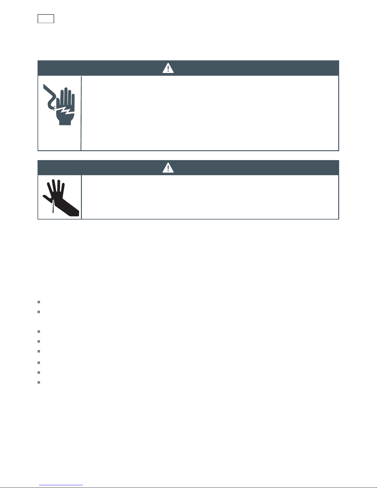
Dimensions and clearances
The cooker must be installed no less than 50 mm away from any side walls which exceed the
height of the cooktop.
The cabinetry surrounding the cooker must be made of heat-resistant material and must be able
to withstand temperatures of 65 °C above room temperature.
Do not install the cooker near flammable materials (eg curtains).
If you stand the cooker on a pedestal, make sure you provide safety measures to keep it in place.
Installing the cooker above a plinth without fitting the adjustable feet
In that case the cooker stands directly above the plinth; make sue you provide safety measures
to keep it in place. Revise the installation dimensions accordingly considering that the feet have
the following measures: min 155 mm - max 180 mm.
50 mm
650 mm
500 mm
450 mm
Installation instructionsInstallation instructions
Cooker overall dimensions [mm]
•
height:
min 892 - max 917
•
product width: 898
•
depth: 600
•
cavity width 900
Fig. 1 Dimensions and
distances from cooker
7
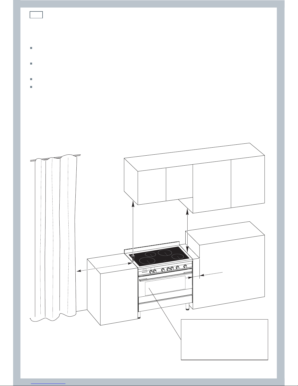
Fig. 4 Top of feet to be
screwed in tightly
Installation instructions
256.5 - 281.5
mm (*)
(*) Depending on
feet adjustment
Fitting the adjustable feet
Important!
It is possible to install the cooker above a plinth without fitting the adjustable feet.
In that case the cooker will stand directly above the plint; make sure you provide safety measures to
keep it in place.
Fit the adjustable feet before using the cooker.
1
Rest the rear of the cooker on a piece of the polystyrene packaging, exposing the base for
fitting the feet.
2
Fit the four feet by screwing them tight into the support base as shown.
Levelling the cooker
Level the cooker by screwing the feet in or out,
as shown in Fig.5.
Fig. 3 Location of feet Fig. 5 Levelling the cooker
Locating the area for electrical connection
Dotted line showing
the position of the
cooker when installed
Area for electrical
connection
Fig. 2 Area for electrical connection
8
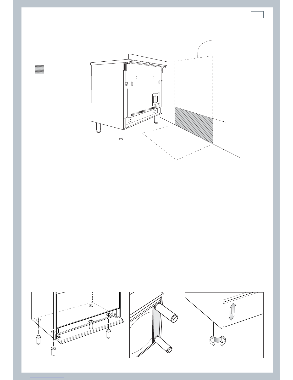
Installation instructionsInstallation instructions
Important!
To prevent damaging the adjustable feet, ensure
the cooker is always lifted by two people.
Do not lift the cooker by the door handles.
DO NOT DRAG the cooker. Lift the feet clear of the
floor.
Moving the cooker
Fig. 6 Correctly lifting the cooker
Fig. 8 Incorrectly lifting the cookerFig. 7 Incorrectly moving the cooker
Fixing the backguard
Before installing the cooker, assemble the
backguard “C” .
The backguard “C” can be found packed
at the rear of the cooker.
1
Before assembling, remove any protective
film/adhesive tape.
2
Remove the two spacers “A” and the
screw “B” from the rear of the cooktop.
3
Assemble the backguard as shown and
fix it by screwing the central screw “B”
and the spacers “A”.
A
B
C
Fig. 9 Assembling
the backguard
9
1
2
65
mm
833 mm
0
+ 25
min 210 mm
max 235 mm
(depending on feet adjustment)
898 mm (product width)
Installation instructions
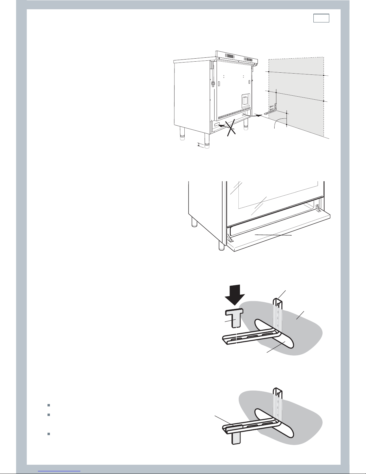
Fitting the anti-tilt bracket
Important!
To restrain the appliance and prevent it tipping
accidentally, fit a bracket to its rear to fix it
securely to the wall.
For New Zealand and Australia only: make
sure you also fit the supplied lock pin to the
anti-tilt bracket.
If installing the cooker above a plinth (without
fitting the adjustable feet), revise the
installation dimensions accordingly
considering that the feet have the following
measures: min 155 mm - max 180 mm.
To fit the anti-tilt bracket:
1
After you have located where the cooker
is to be positioned, mark on the wall the
place where the two screws of the anti-tilt
bracket have to be fitted. Please follow the
indications given in Fig10a.
2
Drill two 8 mm diameter holes in the wall
and insert the plastic plugs supplied.
Important!
Before drilling the holes, check that you will not
damage any pipes or electrical wires.
3
Loosely attach the anti-tilt bracket with the
two screws supplied.
4
Move the cooker to the wall and adjust the
height of the anti-tilt bracket so that it can
engage in the slot on the cooker’s back, as
shown in Fig.10a.
5
Tighten the screws attaching the anti-tilt
bracket.
6
Push the cooker against the wall so that the
anti-tilt bracket is fully inserted in the slot
on the cooker’s back.
7
New Zealand and Australia only: access the
bracket and fit the lock pin;
Open the pivoting panel (Fig. 10b).
Fit the lock pin through the bracket,
as shown (Fig.10c).
Close the pivoting panel.
Fig. 10a Fitting the anti-tilt bracket
Fig. 10b Opening the pivoting panel
Fig. 10c New Zealand and Australia only: fitting the
lock pin through the bracket
Pivoting
panel
Anti-tilt bracket
attached on the
rear wall
Cooker’s
back
Lock pin
Slot on the
cooker’s back
Lock pin
correctly
tted

10
Installation instructions
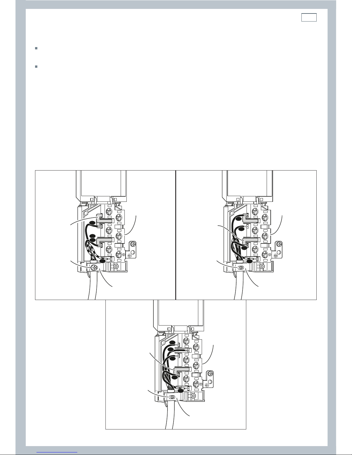
Connecting the power supply cable
Important!
This cooker must be connected to the electricity supply only by an authorised person.
To connect the power supply cable to the cooker, it is necessary to:
1 Unhook the terminal board cover by inserting a screwdriver into the two hooks ‘A’ (fig. 11).
2 Unscrew the screw ‘D’ and open completely the cable clamp ‘E’ (figs. 13).
3 Position the U bolts ‘F’ onto terminal board ‘G’ (figs. 13) according to the diagrams in fig. 12.
4 Connect the phase, neutral and earth wires to terminal board ‘G’ according to the diagrams in
figs. 12 - 13.
5 Strain the feeder cable and block it with cable clamp ‘E’ (by screwing screw ‘D’).
6 Close the terminal block cover (check the two hooks ‘A’ are correctly hooked).
Important!
To connect the power supply cable DO NOT unscrew the screws fixing the cover plate behind the terminal
block.
WARNING: If the power supply cable is damaged, it must be replaced only by an authorised service agent in
order to avoid a hazard.
Voltage and power consumption
220-240/380-415 V 3N~ 50/60 Hz 11080 W (diversity not applied)
A
PE
N (L2)
L
1
220-240 V
1
2
3
4
5
1
2
3
4
5
PE
380-415 V 2N
N
L1
L2
1
2
3
4
5
PE
380-415 V 3N
N
L1
L3
L2
Fig. 11 Terminal block Fig. 12 Connection diagrams
11
Installation instructions
Feeder cable section
In Australia and New Zealand: this cooker must be connected to electrical supply using V105
insulated cable.
In United Kingdom and Ireland: this cooker must be connected to electrical supply using H05RR-F
or H05VV-F insulated cable.
220-240 V~ 3 x 6 mm
2
(*)
380-415 V 3N~ 5 x 2,5 mm
2
(*)
380-415 V 2N~ 4 x 6 mm
2
(*)
* Connection with wall box connection.
- Diversity factor applied.
- A diversity factor may be applied to the total loading of the appliance only by a suitably
qualified person.
~
1
2
3
5
4
N
L2
PE
L1
G
F
D
E
220-240 V
1
2
3
5
4
PE
N
L1
L2
G
F
D
E
~
380-415 V 2N
1
2
3
5
4
PE
N
L1
L2
L3
G
F
D
E
~
380-415 V 3N
Fig. 13 Connection diagrams
12
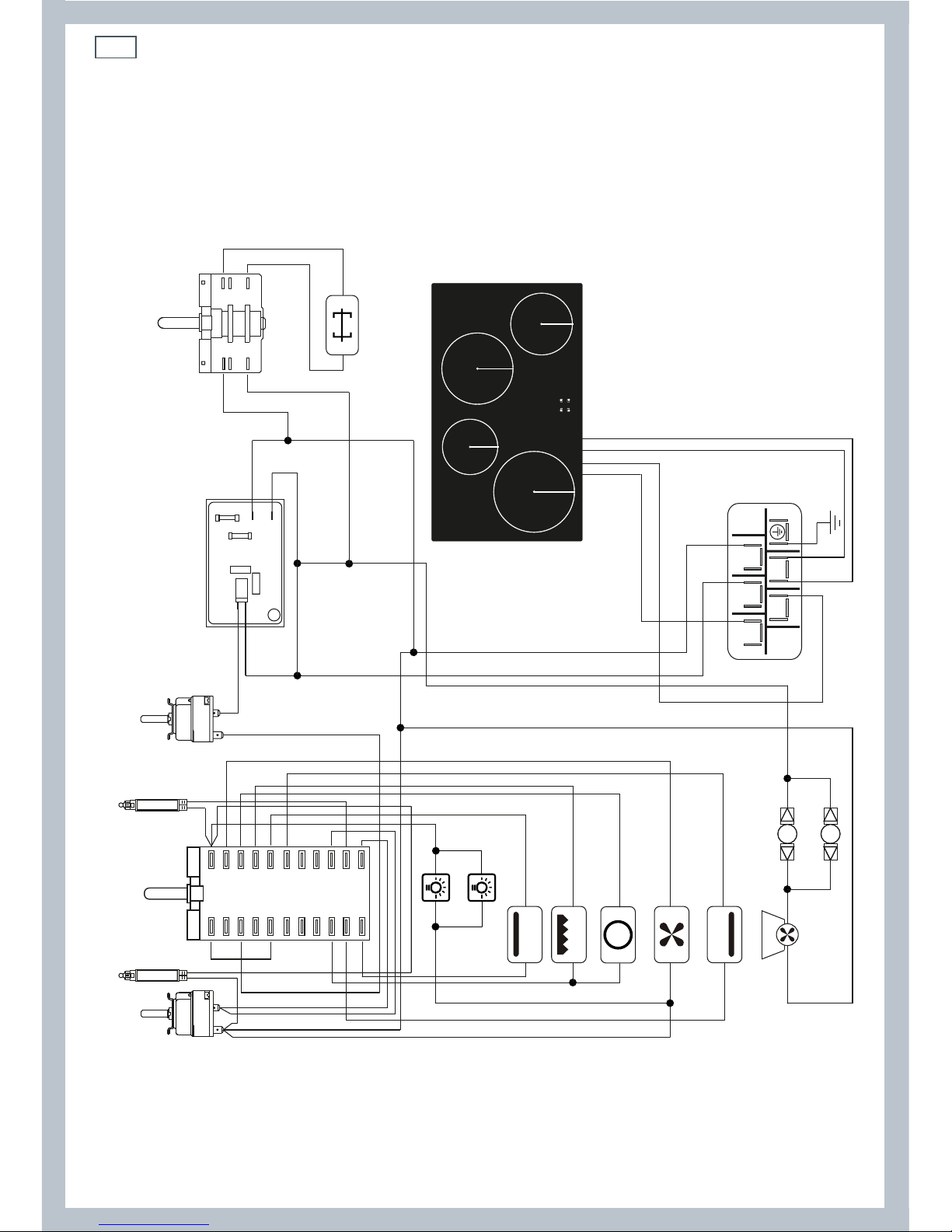
Wiring diagram
Installation instructions
TM
S2
S1
F1
LF
LF
C
G
CIR
V
S
CF
TL
TL
M
T
1a2a3a4a5a6a7a8a9a
10a
11a
1
1
N/7
L/8
1a
1
2
P1
135
24
P2
2345678
9
10
11
TMS
PR
F2
GIR
IH

13
Wiring diagram key
F1 Oven function selector (switch)
TM
Oven thermostat
TMS
Safety thermostat
TL
Thermal overload (n.o.)
S1
Oven temperature indicator light
S2
Oven ON indicator light
PR
Oven programmer
F2
Rotisserie selector (switch)
GIR
Rotisserie motor
LF
Oven lamps
IH Induction cooktop
S
Oven bottom heating element
C
Oven top heating element
G
Oven grill heating ele ment
CIR
Oven fan (circular) heating element
V
Oven fan motor
CF
Cooling fan motor
M
Terminal block
T
Earth connection
Installation instructions
14
11
Using your oven for the rst time
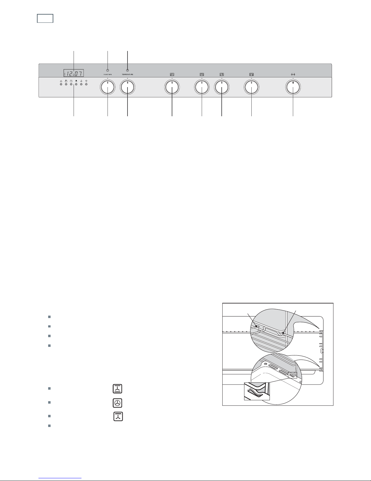
Fig. 14 Control panel
Before using your new oven, please:
1
Read this user guide, taking special note of the ‘Safety and warnings’ section.
2
Remove all accessories and packaging. Peel the protective film off all surfaces and accessories.
3
Set the clock. The oven will not work until the clock has been set.
4
If your model has sliding shelf supports, check that these are fitted. If they aren’t, see ‘Care and
cleaning’ for instructions.
5
Slide in the shelves you will need, making sure that:
they are between the two wires of a shelf position;
the stop notches point down;
the guard rail is at the back.
Note: the grill tray should be positioned between
the two wires of a shelf position and orientated
as shown.
6
Heat the oven on maximum for:
60 minutes in the position
30 minutes in the position
15 minutes in the position
There will be a distinctive smell while you are
conditioning your oven. This is normal, but make
sure your kitchen is well ventilated during the conditioning.
7
Once cooled, wipe out the oven with a damp cloth and mild detergent, and dry thoroughly.
Fig. 15 Correct position of shelves
and grill tray
1
1
Control buttons
2
Clock display
3
Function dial
4
Temperature dial
5
Front left zone
6
Rear left zone
7
Rear right zone
8
Front right zone
9
Rotisserie dial
10
Function indicator light
11
Temperature indicator light
2
34 5 67 8 9
10
Guard rail
Stop notch
Stop
notch
(NZ AU models only)
 Loading...