


AeroCare clothes dryer
Installation instructions
and User guide
US

WARNING!
For your safety the information in
this manual must be followed
to minimize the risk of fire or
explosion or to prevent property
damage, personal injury or death.
—Do not store or use gasoline or other
flammable vapors and liquids in the
vicinity of this or any other appliance.
—WHAT TO DO IF YOU SMELL GAS
• Donottrytolightanyappliance.
• Donottouchanyelectricalswitch;do
not use any phone in your building.
• Cleartheroom,buildingorareaofall
occupants.
• Immediatelycallyourgassupplierfrom
a neighbor’s phone. Follow the gas
supplier’s instructions.
• Ifyoucannot reachyourgassupplier,
call the fire department.
—Installation and service must be
performed by a qualified installer, service
agency or the gas supplier.
The Governor of California is required to publish a list of substances known to the state of
California to cause cancer or reproductive harm and requires business to warn customers of
potential exposures to such substances.
WARNING!: Gas appliances contain or produce substances, which can cause death, or
serious illness and which are known to the State of California to cause cancer, birth
defects, or other reproductive harm. To reduce the risk from substances in fuel or from fuel
combustion, make sure this appliance is installed, operated, and maintained according to
the manufacturer’s instructions.
In the Commonwealth of Massachusetts
Installation of this appliance must be performed by a contractor, plumber or gasfitter who is
qualified or licensed by the state.

Contents
Introduction 2
Important safety instructions 3
Installation instructions 7
The first time you turn your dryer on 48
Getting started quickly 50
AeroCare controls 52
Sorting and loading 54
Dryer cycles 56
Drying special items 61
Drying cycle options 63
Dryer operation 66
Care labels 68
Drying rack 69
Customizing dryer cycles 70
Changing pre-set options 71
Caring for your dryer 73
Before you call for service
User warnings 76
Fault codes 76
Solving operating problems 77
Solving drying problems 80
Limited warranty 82
How to get service 84
1
Important!
SAVE THESE INSTRUCTIONS
The models shown in this User Guide may not be available in all markets and are
subject to change at any time. For current details about model and specification
availability in your country, please visit our website listed on the back cover or
contact your local Fisher & Paykel dealer.
2
Introduction
Thank you for buying a Fisher & Paykel AeroCare clothes dryer. We are very proud of this dryer
and trust it will serve you well for many years.
At Fisher & Paykel we aim to provide innovative products that are simple to use, ergonomic,
energy efficient and kind to the environment. Thousands of tonnes of washing and 75 years of
laundry experience have been programmed into your dryer to help give you the best possible
performance.
We have developed this dryer to treat your clothes with the utmost care, drying them gently, so
they will look better for longer. We trust you’ll enjoy the benefits of numerous drying cycles and
options, its extra large capacity and reverse tumbling.
Please take the time to read this User Guide carefully. It will help you to operate and maintain
your new AeroCare dryer. Your safety and the safety of others is very important. Located on your
dryer and throughout this guide are safety messages and instructions; it is important that you
understand and follow them.
We hope you enjoy your new dryer.
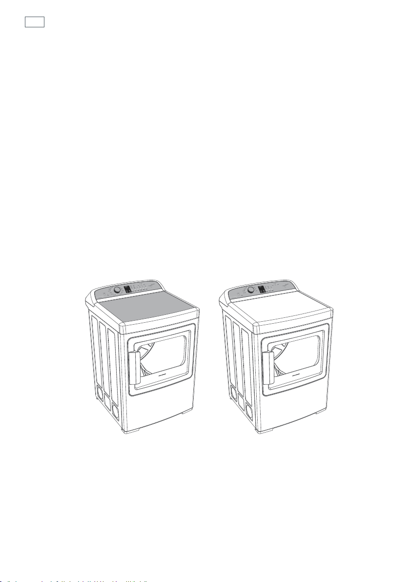
Fig.1 AeroCare dryer models
Important!
It is important that this User Guide should be retained with your AeroCare clothes dryer for
future reference. Should the appliance be sold or transferred to another owner, please ensure
that the User Guide is left with the appliance. This will ensure that the new owner can familiarize
themselves with the information and warnings contained within the Guide.
Important safety instructions
Symbols
Symbols will be used in this Guide to highlight when extra care is required. Abide by these at all
times to ensure you and your family are not harmed while operating your dryer.
It is important to always act with caution and use common sense when operating your dryer.
Use only as instructed by the User Guide.
This is the safety alert symbol. This symbol alerts you to hazards that can
present risk of losing life, or hurt you and others.
The safety alert symbol and the word WARNING will precede all safety
messages. This word means:
3
WARNING
All safety messages will identify the hazard, tell you how to reduce the chance of injury,
and tell you what can happen if the instructions are not followed.
You can be at risk of losing your life or being seriously
injured if you don’t follow instructions.

4
Important safety instructions
WARNING!
Electric Shock Hazard
Follow the safety precautions outlined in this User Guide.
Failure to do so can result in death or electrical shock.
Important safety precautions
Read all instructions carefully before using this dryer. Use this dryer only for its intended purpose
as described in this User Guide.
Installation must conform with local codes, or in absence of local codes, with the National Fuel Gas
Code, ANSIZ223.1/NFPA54 or the Canadian Natural Gas and Propane Installation Code, CSAB149.1
Installation and service must be performed by a qualified or licensed contractor, plumber or gasfitter
qualified or licensed by the state, province, or region where this appliance is being installed.
This dryer must be properly installed and located in accordance with the Installation Instructions
before it is used.
This dryer, when installed, must be electrically grounded in accordance with local codes, or in the
absence of local codes, with the National Electrical Code, ANSI/NFPA70, or the Canadian Electrical
Code, CSAC22.1.
Do not install or store the dryer where it will be exposed to water or exposed to the weather.
Connect to a properly protected, rated and sized power supply circuit to avoid electrical overload.
Do not repair or replace any part of the appliance or attempt any servicing, unless specifically
recommended in the published user repair instructions that you understand and have the skills to
carry out.
To minimize the possibility of electric shock, unplug this dryer from the power supply or disconnect
the dryer at the household distribution panel (by removing the fuse or switching off the circuit
breaker) before attempting any user maintenance or cleaning.
When disconnecting the dryer, pull by the plug rather than the cord or junction of the cord plug, to
avoid damage to the cord or junction of the cord plug.
Make sure the cord is located so that it will not be stepped on, tripped over or otherwise subject to
stress or damage.
Do not tamper with the controls.
Note: Touching the POWER button does NOT disconnect the dryer from the power supply, even
though the lights are out.
Do not operate this dryer if it is damaged, malfunctioning, partially disassembled or has missing
or broken parts, including a damaged cord or plug.
This dryer must be directly connected to an approved fixed electrical outlet. It cannot be plugged
into an extension cord or an adaptor plug.
Do not use the dryer if there is water on the floor near the dryer. Call an Authorized Service Agent
if there is a leak.

Important safety instructions
WARNING!
Fire Hazard
Only dry fabrics that have been washed with water.
Do not use a drying cycle with heat to dry articles containing foam
rubber or similarly textured rubber-like materials. Only dry on the
AIRDRY cycle.
A clothes dryer produces combustible lint and must be exhausted
outdoors. Take care to prevent the accumulation of lint around the
exhaust opening and in the surrounding area.
Do not use fabric softeners or products to eliminate static unless
recommended by the manufacturer of the fabric softener or product.
Failure to follow these instructions can result in death or personal injury.
To reduce the risk of fire in a tumble dryer the following should be observed:
Do not place items in a tumble dryer that have previously been cleaned in, washed in, soaked in,
or spot cleaned with flammable liquids or solids. They give off vapors which are a fire or explosion
hazard. Highly flammable substances commonly used in domestic environments include acetone,
denatured alcohol, gasoline, kerosene, some brands of spot removers and dry cleaning solvents,
turpentine, waxes, wax removers, vegetable oil, fish oil, massage oil, and cooking oil.
Do not place items exposed to cooking oils in your dryer. Items contaminated with cooking oils
may contribute to a chemical reaction that could cause a load to catch fire.
Do not leave hot oil-affected items in a pile or stack. This can prevent heat from escaping and can
create a fire hazard. Oil-affected items can ignite spontaneously, especially when exposed to heat
sources such as a tumble dryer. The items become warm causing an oxidation reaction in the oil. This
oxidation creates heat. If the heat cannot escape the items can become hot enough to catch fire.
Do not use a drying cycle with heat to dry items containing rubber, foam rubber, plastic or similar
materials (such as padded bras, bath mats, rugs, bibs, baby pants, plastic bags, pillows etc), as these
materials might melt or burn. Some rubber materials when heated can under certain circumstances
produce fire by spontaneous combustion. Only dry on the AIR DRY cycle.
Unless specifically recommended by their manufacturer, do not use fabric softeners or similar
products in a tumble dryer.
Do not store or use gasoline or other flammable gases and liquids near this or any other appliance.
Keep the area around the exhaust opening and adjacent surrounding areas free from the
accumulation of combustible materials such as lint, dust, dirt, paper, rags, chemicals etc.
Do not store any items that may burn or melt (such as paper materials, plastics or plastic containers
etc) next to the dryer.
Clean the lint filter each time you use the dryer, before or after each load.
The dryer must be exhausted to the outside. Carefully follow the exhausting and venting details in
the Installation Instructions.
The interior of the appliance and the exhaust duct should be cleaned periodically by qualified
service personnel.
5

6
Important safety instructions
Safe use of the dryer
Do not allow children to play inside, on, around or with this dryer or any other appliance. Close
supervision is necessary if this dryer is used near children.
Never climb on, climb into, or stand on the dryer top, or drum, or apply weight to the door.
Keep the floor around your dryer clean and dry to reduce the possibility of slipping.
If your dryer is running and you want to unload or add clothes, touch START/PAUSE then open
the dryer door.
Do not reach into the appliance if the drum is moving.
Undergarments that contain metal reinforcements should not be placed directly in the dryer.
Damage to the dryer can result if the metal reinforcements come loose during drying. If you wish
to dry these items use the drying rack supplied with your dryer.
BEFORE THE APPLIANCE IS REMOVED FROM SERVICE OR DISCARDED, REMOVE THE DOOR.
SAVE THESE INSTRUCTIONS
Installation instructions
WARNING! – Risk of fire
Clothes dryer installation must be performed by a qualified installer.
Install the clothes dryer according to the manufacturer’s instructions and local codes.
DO NOT install the clothes dryer with flexible plastic venting materials. If flexible
metal (foil-type) duct is installed, it must be identified by the dryer manufacturer
as suitable for use with clothes dryers and installed in strict accordance with the
instructions found on pages 26 to 38 of these installation instructions. Flexible
venting materials are known to collapse, be easily crushed and trap lint. These
conditions will obstruct dryer airflow and increase the risk of fire.
The dryer must be vented to the outdoors.
Use only rigid metal 4” (102 mm) diameter ductwork inside the dryer cabinet and use
only UL-listed transition ducting between the dryer and the home duct.
Do not install or store this appliance in any location where it could be exposed to
water and/or weather.
To reduce the risk of severe injury or death, follow all installation instructions.
SAVE THESE INSTRUCTIONS
Before you begin
7
Read the important safety instructions on the inside cover and on pages 3 – 6 before you start
installing the dryer.
Check to make sure you have all the tools and parts necessary to correctly install this appliance.
Tools required:
Adjustable wrench 10” (254 mm) × 2 (for gas connection).
Flat-blade screwdriver.
Slip joint pliers.
Pipe wrench 8” (203 mm) (for gas connection).
Phillips screwdriver.
Drill with ⁄” (3 mm) drill bit (for bottom venting only).
Caulking gun and compound (for installing new exhaust vent).
Glasses.
Gloves.
Knife.
Hacksaw.
Spirit level.

8
Installation instructions
Materials:
4”(102mm) diameter rigid metal duct (recommended).
4”(102mm) diameter UL-listed flexible metal duct (if needed).
4”(102mm) diameter metal elbow(s).
Flexible metal gas line connector (for gas connections only).
Duct or spring clamps(2).
Pipe joint compound (pipe dope or tape) for gas pipe connections, resistant to LP Propane,
butane and natural gas (for gas connections only).
Exhaust/vent hood.
Duct tape.
Soap solution for gas leak detection (for gas connections only).
¾”(19mm) strain relief (electric connections only).
Dryer power cord kit (power cord is not supplied with United States models).
Requirement: UL-rated 120/240V, 30 amp with 3 or 4 prongs. Identify the plug type needed from
the existing house receptacle before purchasing. Length of cord must be at least 5 feet (1.5 m) long.
To the installer
Read these instructions completely and carefully.
These instructions must be left with the home owner for future reference.
Correct installation is the responsibility of the installer.
Installation of this appliance must be performed by a qualified installer.
The dryer must be exhausted to the outdoors.
Remove the door from an old dryer before it is removed and discarded.
The wiring diagram and service information can be found in the control console.
The limited warranty does not cover product failure as a result of improper installation.
The dryer must be installed in a location where the temperature is above 50°F (10°C) to ensure
suitable operation of the dryer control system.
UL-listed duct material must be used. Discard existing plastic or metal foil duct and replace with
UL-listed duct material.
Observe all governing codes and ordinances.
Follow the installation instructions carefully.
Important!
Save these instructions for local electrical inspector’s use.
Observe all governing codes and ordinances.
Install the clothes dryer according to the manufacturer’s instructions and local codes.
Installation instructions
Unpacking
To ensure the best performance from the dryer, please follow the instructions below.
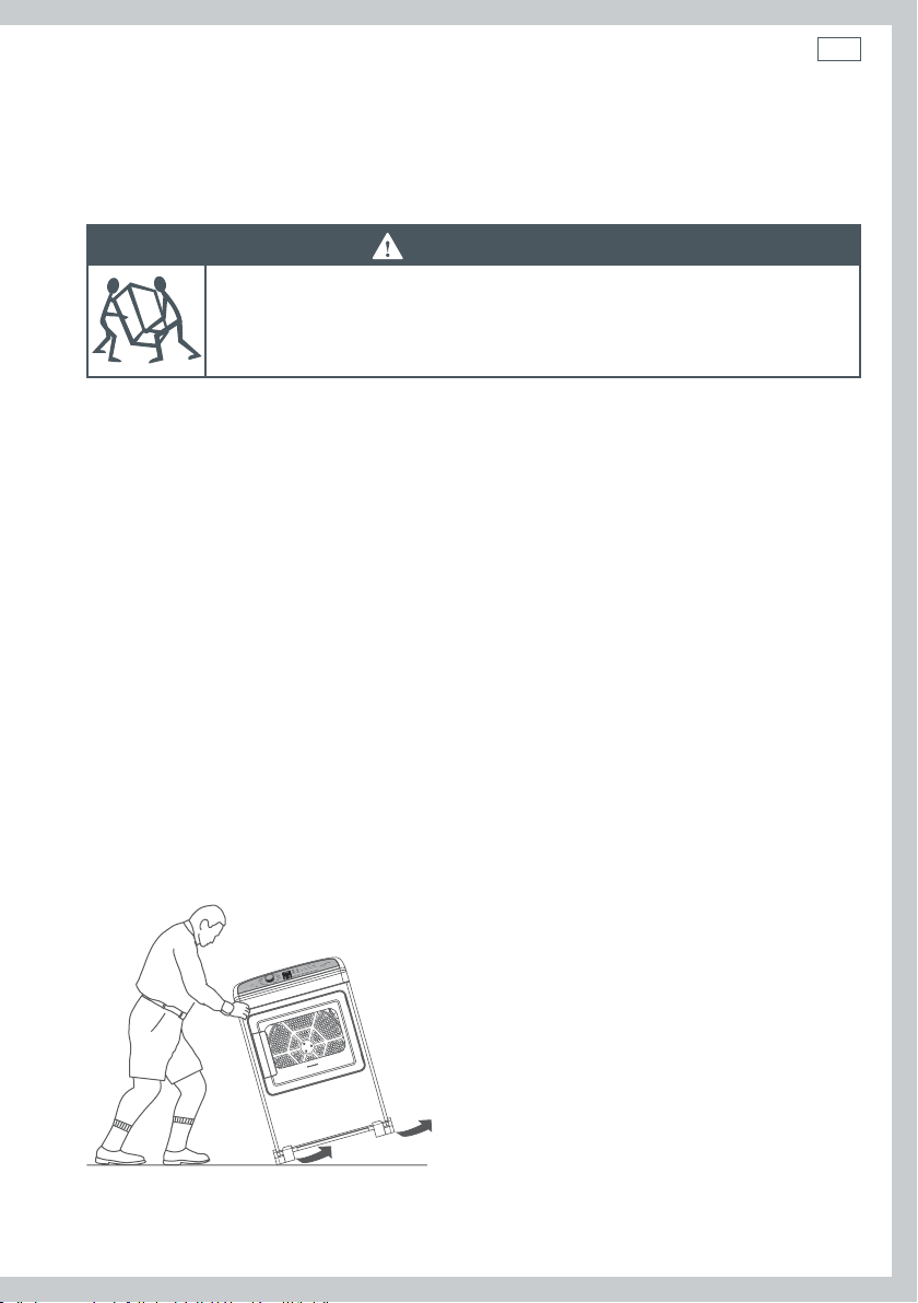
WARNING!
Excess Weight Hazard
Use two or more people to move and install the dryer.
Failure to do so can result in back or other injury.
Important!
Only remove the packaging at the customer’s premises.
This will ensure the appliance arrives in pristine condition and reduces the risk of damage during
transportation to the customer’s home.
1. Remove packaging
Remove all of the outer packaging. Dispose of unwanted packaging thoughtfully.
2. Discard packing material from around dryer feet
Tilt the dryer sideways and remove the foam shipping pads by pulling at the sides and breaking
them away from the dryer feet. Be sure to remove all the foam pieces before continuing with
installation.
9
3. Drying rack
Open the door. Remove the tape holding the drying rack in place. Remove the rack and remove
protective tape from ‘legs’ of rack.
4. Accessories
Remove the accessories from inside the dryer.
Fig.2 Unpacking your dryer correctly

10
Installation instructions
Location requirements
WARNING!
Explosion Hazard
Keep flammable materials and vapors, such as gasoline, away from
thedryer.
Place dryer at least 18” (460 mm) above the floor for a garage installation.
Failure to do so can result in death, explosion, fire, or burns.
The dryer must be installed or stored in an area which is not exposed to water or weather.
It is extremely important that the dryer is installed in a well ventilated location. This dryer must
exhaust air outdoors. Do not install the dryer in any room or closet which does not permit the
free flow of replacement air. The free area of any opening for the introduction of outside air shall
not be less than twice the area of the dryer exhaust outlet.
The area in which the dryer is located must be kept clear and free from combustible materials,
gasoline and other flammable vapors and liquids. A dryer produces combustible lint so the area
around the dryer must be cleaned regularly to keep it free of lint.
Make sure dryer is in a suitable location for installation.
Consider installing the dryer before the washing machine in a side by side installation, this will
allow better access to electrical and exhaust connections.
Installation instructions
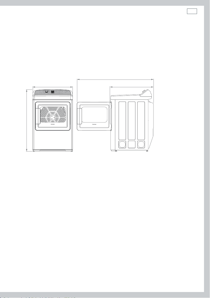
Minimum clearance required other than alcove or closet installation
Allow sufficient room behind the dryer for the exhaust. The air intake is at the rear of the dryer.
Ensure that there is a sufficient air passage on each side of the dryer for intake air.
The minimum clearance to combustible surfaces and for air openings are: 1” (25 mm) clearance
both sides, 2” (51 mm) clearance at the front, and 1” (25 mm) clearance at the rear, or 5” (127mm)
clearance if the dryer exhaust duct is at the rear. Consideration must also be given to provide
adequate clearance for proper operation and service.
52 ½” (1332 mm)
27” (683 mm)
41 ½” (1051 mm)*
* Excludes adjustable foot height
29 ½” (743 mm)
11
Fig.3 AeroCare dimensions
12
Installation instructions
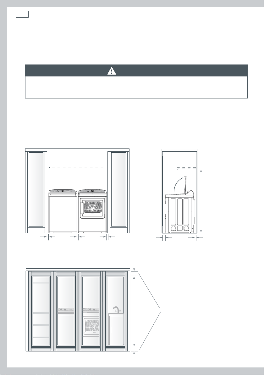
Requirements for alcove or closet installation
Your dryer is approved for installation in an alcove or closet (as specified on the dryer back).
WARNING!
When installing a dryer in a closet alcove it MUST be exhausted to the outdoors. No
other fuel burning appliance can be installed in the same closet or alcove.
The total ventilation area must be a minimum of 60 sq. in. (387 cm2) of open area equally
distributed. If the closet contains both a washer and a dryer, doors must contain a minimum of
120 sq. in. (774 cm
louvered door with the minimum air opening is acceptable). Minimum installation clearances are
required but more clearance is recommended.
2
) of open area equally distributed. The openings must never be obstructed (a
minimum clearance
required
56 ⁄” (1430 mm)
1” (25 mm) 1” (25 mm) 1” (25 mm) min 1” (25 mm)
min 2” (50 mm)
(rear of product to wall)
Fig.4 Minimum clearances
total ventilation area
120 in.sq (774 cm)
Fig.5 Minimum ventilation

Installation instructions
Requirements for alcove or closet installation continued
The closet should be vented to the outdoors to prevent gas pocketing in case of a gas leak in the
supply line.
No other fuel-burning appliance shall be installed in the same closet with the dryer (gas models
only).
Note: when the exhaust duct is located at the rear of the dryer, minimum clearance required
from the wall is 5” (127 mm).
Bathroom or bedroom installation
The dryer MUST be vented to the outdoors. See “Exhausting the dryer” (page 26).
Mobile or manufactured home installation
Installation is required to comply with the Manufactured Home Construction & Safety Standard,
title 24CFR, part 3280. If or when such standard is not applicable, installation must comply with
the American National Standard for Mobile Home, ANSI/NFPA No. 501.
The dryer MUST be vented to the outdoors with the termination securely fastened to the mobile
home structure.
Exhaust ducts MUST be securely fastened to a non-combustible portion of the mobile home
structure.
The exhaust MUST NOT be terminated beneath a mobile or manufactured home.
The exhaust duct material MUST BE METAL.
The exhaust duct MUST NOT be connected to any other duct, vent, or chimney, or be vented into
a wall, ceiling or concealed space of a building.
Do not use sheet metal screws or other fastening devices which extend into the interior of the
exhaust vent.
13
In addition to the above, for gas dryer models:
Kit 14-D346-33 MUST be used to attach the dryer securely to the structure.
Provide an opening with a free area of at least 25 sq. in. (161 cm2) for introduction of outside air
into the dryer room.
Residential garage installation
Dryers installed in residential garages must be elevated 18” (460 mm) above the floor.
The installation must conform with local codes or, in the absence of local codes, with the
National Electrical Code, NFPANO.70 (for electric dryers) or National Fuel Gas Code,
ANSIZ223.1/NFPA54 (for gas dryers) in the United States; and the Canadian Electrical Code
CSAC22.1 (for electric dryers) or Natural Gas and Propane Installation Code, CSAB149.1 (for gas
dryers), in Canada.
14
Installation instructions
Connecting a gas dryer (skip for electric dryer)
Refer to page 7 for tools required.
Note: installation and service of this dryer must be performed by a qualified installer, service
agency or the gas supplier.
Gas supply and installation requirements
In the Commonwealth of Massachusetts:
Installation of the dryer must be completed by a plumber or gas fitter licensed by the state.
When using ball-type gas shut-off valves, the t-handle type shall be used.
If using a flexible gas connector, this must not exceed a length of 3 feet in total.
WARNING!
Explosion Hazard
Installations must be performed by a qualified or licensed contractor,
plumber, or gasfitter qualified or licensed by the state, province, or
region where this appliance is being installed.
Use a new AGA or CSA approved gas supply line.
Install a shut-off valve in an accessible place.
Only use a gas shut-off valve approved for use within the state, province,
or region where this appliance is being installed.
Securely tighten all gas connections.
If connecting to LP Gas, have a qualified person make sure gas pressure
does not exceed 13” (330 mm) water column.
Failure to follow these instructions can result in death, explosion, or fire.

Installation instructions
WARNING!
To Reduce the Risk of Fire, Electrical Shock and Personal Injury:
Before connecting the dryer turn off circuit breaker(s) or remove the dryer’s circuit
fuses at its electrical box. Ensure the power cord is unplugged from the wall socket.
Ensure the gas shut off valve in the supply line is OFF.
Use only new ducting materials. Remove and discard old flexible gas connector and
duct material.
Gas type
This gas dryer is equipped with a valve and burner assembly for use only with natural gas. Your
local service organization can convert this dryer for use with propane (LP) gas, using conversion
kit WC254C1258A001.
Important!
All conversions must be completed by correctly trained and qualified personnel, in accordance
with all local codes and ordinances.
Pressure testing
The dryer must be disconnected from the gas supply piping system during any pressure testing
of the system at a pressure greater than 0.5psi (3.5kPa).
The dryer must be isolated from the gas supply piping system by closing the equipment shut-off
valve during any pressure testing of the gas supply piping of test pressure equal to or less than
0.5psi (3.5kPa).
15
Gas supply
A ⁄” National Pipe Taper (NPT) plugged tapping must be installed immediately upstream of the
gas supply connection to the dryer. This must be accessible for test gauge connection. Please
contact your local gas utility if you have questions regarding the installation of the plugged
tapping.
The gas supply line is to be ½” (12.7 mm) rigid pipe. The line must be equipped with an
accessible shut-off which is within 6 feet (1.8 m) of the dryer AND in the same room as the
appliance.
Pipe thread compound appropriate for Natural or Propane (LP) gas must be used.
New flexible metal gas line connector should be used to connect the dryer and gas supply.
16
Installation instructions
Elevation adjustment
The input ratings of gas operated clothes dryers are based on their operation at sea level, and
need not be adjusted for operation at or below 2000 ft. (610 m) elevation. For operation at
elevations above 2000feet (610m), input ratings should be reduced at a rate of four percent per
1000feet (305m) elevation above sea level.
Installation must conform to all local codes and ordinances. In the absence of local codes and/or
ordinances, installation shall conform to the National Fuel Gas Code, ANSIZ223.1/NFPA54, or the
Natural Gas and Propane Installation Code, CSAB149.1.
Gas supply connection
2 ½” (64 mm)
1 ¾” (45 mm)
Note: add to vertical dimension the
distance between cabinet bottom to floor
⁄” NPT Male thread gas supply
Fig.6 Gas connection at rear of dryer
Installation instructions
Connecting the dryer to the gas supply
Gas connection parts
Ensure you have the following parts before installing the dryer.
Adapter
New metal flexible
gas line connector
⁄” NPT pipe plug for
checking gas inlet pressure
17
Adapter
Elbow
⁄” NPT
Pipe size at least ½” (12.7 mm)
Shutoff valve
Fig.7 Parts required for gas connection
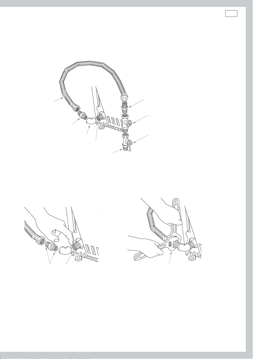
Connecting to dryer
Install a female ⁄” NPT elbow at the gas inlet end of the dryer.
Attach a ⁄” flare union adapter to the female NPT elbow.
Apply pipe compound to the adapter
and dryer gas inlet threads
Fig.8 Attaching elbow and adapter
Using two adjustable wrenches tighten
the flexible gas line connection
Fig.9 Tighten connections
Important!
Securely hold on to the end of the dryer gas inlet with a pipe wrench to help prevent twisting
the inlet.
18
Installation instructions
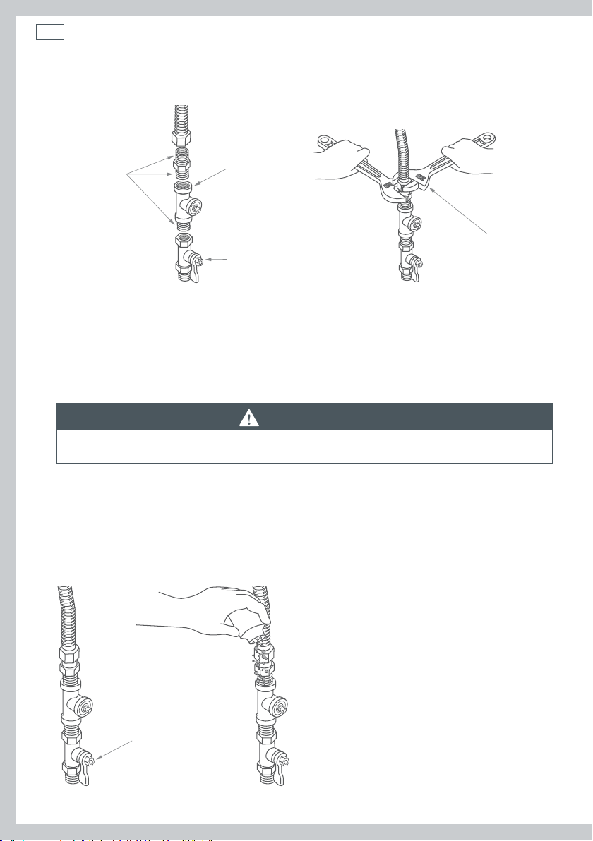
Connecting to supply
Apply pipe
compound to
all male threads
Fig.10 Connecting supply
Plugged
Tapping
Shutoff valve
Using two adjustable
wrenches tighten all
connections
Fig.11 Tightening supply connections
Important!
Do not over tighten the connections.
Test for gas leaks
WARNING!
NEVER use an open flame to test for gas leaks.
Turn on the gas (open the gas shut off valve).
All connections should be checked for leaks with a soapy, or equivalent solution. Apply a soap
(or equivalent) solution to the connection points. If leaks are found, close the shut-off valve,
re-tighten the joint, then repeat the test.
Note: Do not use a solution that contains ammonia. This may cause damage to the brass fittings.
Open gas valve
Fig.12 Testing for gas leaks

Installation instructions
WARNING!
Fire and Poisoning Hazard
Gas leaks cannot always be detected by the sense of smell.
Use of an approved UL or CSA gas detector is recommended.
If a gas leak is detected follow the “What to do if you smell gas” instructions, stated on
the inside font cover of this user guide.
19
20
Installation instructions
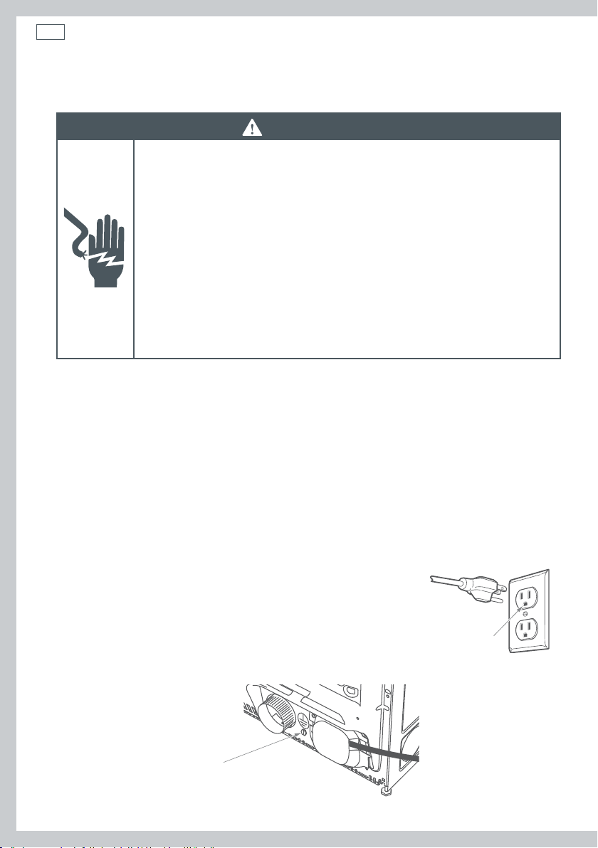
Electrical connection information for gas dryers
WARNING!
Electrical Shock Hazard
Make sure appliance is wired or plugged into a grounded outlet.
Improper connection of the equipment-grounding conductor can result in
a risk of electric shock. Check with a qualified electrician or service person
if you are in doubt as to whether the appliance is properly grounded.
Do not modify the plug if it will not fit the outlet.
Have the proper outlet installed by a qualified electrician.
Do not use an adaptor.
Do not use an extension cord.
Failure to follow these instructions can result in death, fire or
electricalshock.
The appliance must be electrically grounded in accordance with all local codes and ordinances.
In the absence of local codes, the dryer must be electrically grounded in accordance with the
National Electrical Code, ANSI/NFPANO.70, or the Canadian Electrical Code, CSAC22.1.
Electrical requirements for gas dryers
The power supply must be 120V, 60Hz, and connected to a properly grounded branch circuit,
which is protected by a 15 or 20 amp circuit breaker, or a time-delay fuse.
If the electrical supply provided does not meet specifications outlined above, the installation of
an approved outlet by a licensed electrician is recommended.
Important!
The dryer is supplied with a three-prong (grounding) plug for your
protection against electric shock. The plug should be plugged
directly into a correctly grounded three prong power socket.
DONOT cut or remove the grounding terminal from this plug.
Ensure proper ground exists before use.
If local codes permit, an external
ground wire (not provided), which
meets local codes, may be added by
attaching to the green ground screw
on the rear of the dryer, and to a
grounded metal cold water pipe or
other established ground.
Fig.13 Grounding screw
Ensure proper
ground exists
before use
Installation instructions
Connecting an electric dryer (skip for gas dryers) – in the United States only
Refer to page 7 for tools required.
Electrical requirements (electric models only)
WARNING!
To reduce the risk of fire, electrical shock & personal injury:
The appliance must be correctly grounded electrically, in accordance with all local
codes and ordinances. In the absence of these, the appliance shall be grounded in
accordance with the National Electrical Code ANSI/NFPA No. 70.
Before connecting the dryer, turn off the circuit breaker(s) or remove the dryer’s circuit
fuses at its electrical box. Ensure the power cord is unplugged from the wall outlet.
DO NOT leave the cover off the terminal block.
Never use an extension cord or adapter plug with the dryer.
Use only new ducting materials. Remove and discard old duct material.
WARNING!
Electric Shock Hazard
Use a new UL/CSA-listed 30-ampere power cord.
Use a UL-listed strain relief.
Disconnect power before making electrical connections.
Connect neutral wire (white or center wire) to center terminal.
On all four wire installations remove the grounding link and connect the
ground wire to the green ground connecting screw.
Connect remaining two supply wires to remaining two terminals.
Securely tighten all electrical connections.
Failure to do so can result in death, fire, or electrical shock.
21
Note: the wiring diagram is located in the control console.
The dryer must be plugged into or connected to an individual branch circuit, protected by the
correct time delay fuses or circuit breakers. The power supply must be a 3- or 4-wire, single
phase, 120/240 V, 60 Hz, 30 amp circuit.
22
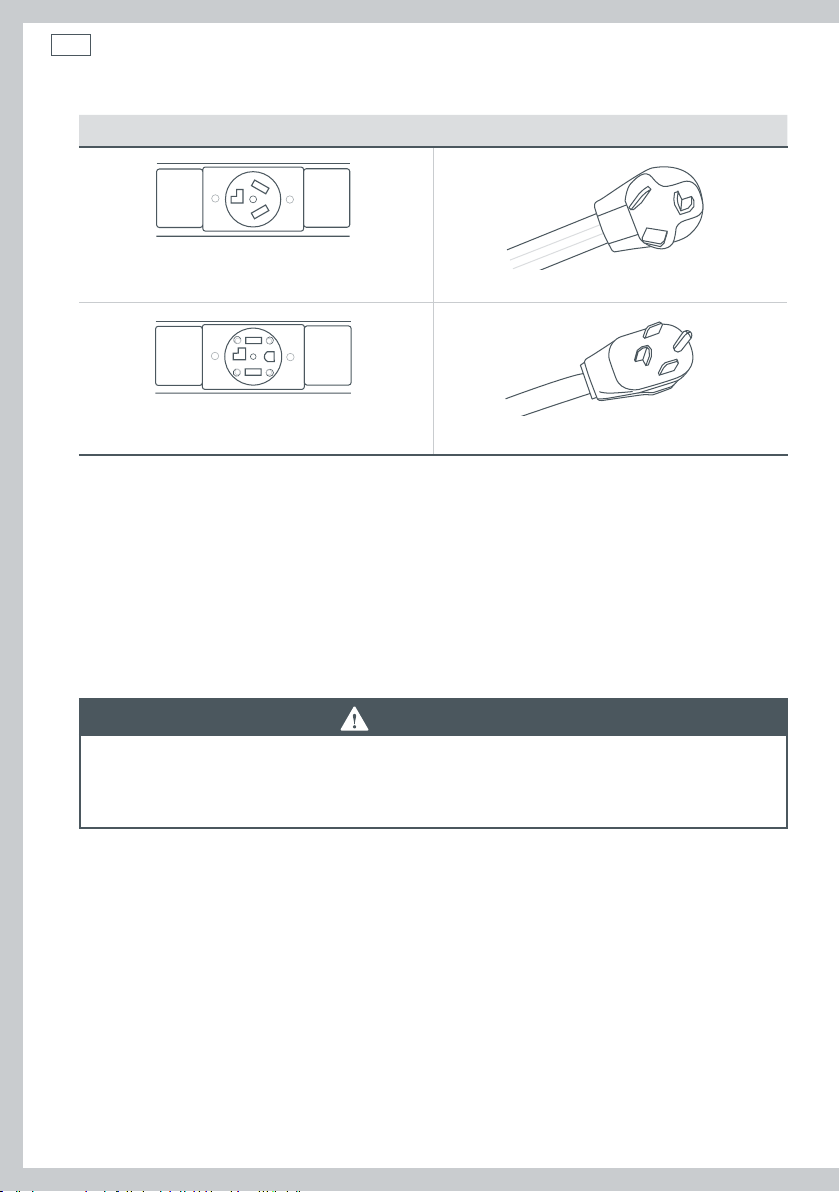
Installation instructions
If your outlet looks like this Choose this power supply cord
3-wire
(NEMA type 10-30R) (See 3-wire connection)
4-wire
(NEMA type 14-30R) (See 4-wire connection)
If a power cord is used, this must be plugged into a 30 amp socket only.
The power cord is NOT supplied with electric model dryers in the United States.
Contact a licensed electrician if the electricity supply does not meet the required specifications.
Grounding instructions
This dryer MUST be connected to a grounded metal, permanent wiring system. Alternatively, an
equipment grounding conductor must be run with the circuit conductors and connected to the
equipment grounding terminal on the dryer.
WARNING!
Improper connection of the equipment-grounding conductor can result in a risk of
electric shock. Check with a qualified electrician or service representative if you are in
doubt as to whether the appliance is properly grounded.
Installation instructions
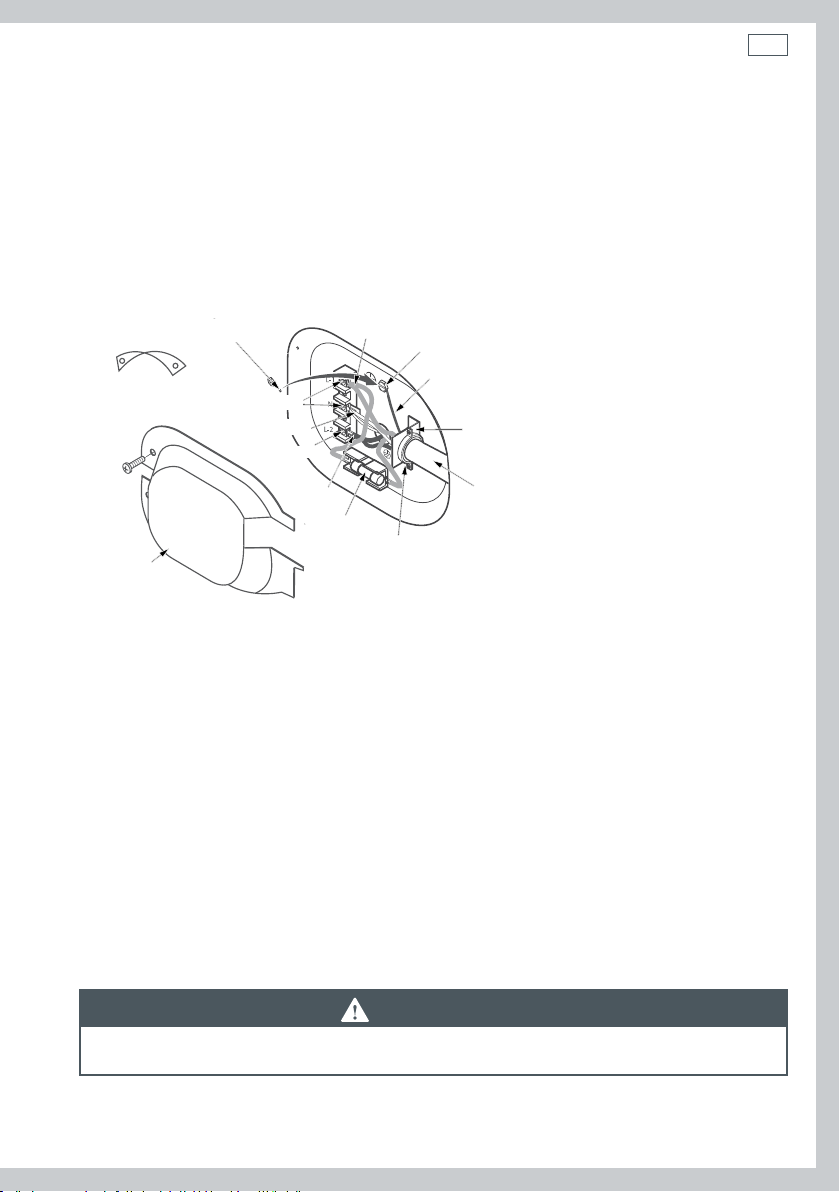
Connecting the dryer using 4-wire connection (must be used for mobile home installation)
Note: the National Electrical Code requires that new constructions use a 4-wire connection to
an electric dryer (effective as of January 1, 1996). Where local codes do not permit grounding
through the neutral, a 4-wire cord must also be used.
Important!
New constructions must NOT use a 3-wire connection.
23
Remove ground strap and discard.
Keep green ground screw
Screws (2)
Neutral (white)
Cover
Fig.14 4-wire connections
1
Turn off the circuit breaker(s) (30 amp) or remove the dryer’s circuit fuse at the electrical box.
2
Ensure the dryer cord is unplugged from the wall outlet.
3
Locate and remove the power cord cover at the lower rear of the dryer.
4
Remove and discard the ground strap. Retain the green ground screw for later relocation (Step 7).
5
Install a ¾” (19 mm) UL-recognized strain relief to the entry hole for the power cord. Move the
Screw
Hot wire
Hot wire
Relocate green ground screw here
Green or yellow wire
Strain relief bracket
120/240V 30 amp power supply cord kit (min
length: 5 feet (1.5 m) marked for use with
dryers & provided with closed loop or spade
Fuse
⁄” (19 mm), UL recognized strain relief
terminals with upturned ends (not supplied).
power cord through the strain relief.
6
Connect the power cord according to the following:
a
Connect the two hot lines to the outer screws of the terminal block (labelled L1 and L2).
b
Connect the neutral (white) line to the center of the terminal block (labelled N).
7
Use the green ground screw to attach the ground wire of the power cord (ie relocate the green
ground screw to the hole above strain relief bracket).
8
Tighten all three terminal block screws completely.
9
Correctly secure the power cord to the strain relief.
10
Replace the power cord cover.
WARNING!
NEVER leave the power cord cover off the terminal block.
24
Installation instructions
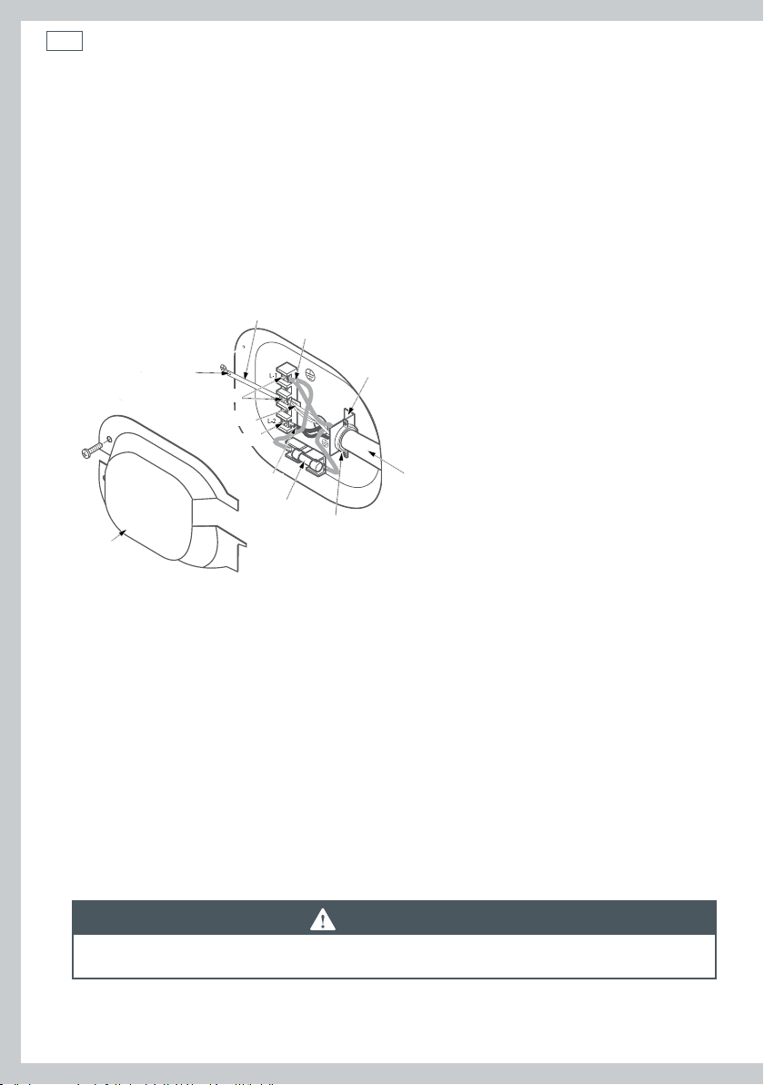
Connecting the dryer using 3-wire connection
Important!
DO NOT use in Canada.
DO NOT use for Mobile home installations, on new constructions, or on recreational vehicles.
NOT for use in areas where local codes prohibit grounding through the neutral conduction.
If required by local codes, install an external ground (not provided) to grounded metal,
a cold water pipe or other established ground as determined by a qualified electrician.
Ground strap
Hot wire
Green ground screw
Screws (2)
Neutral (white)
Screw
Hot wire
Fuse
Cover
Fig.15 3-wire connections
1
Turn off the circuit breaker(s) (30 amp) or remove the dryer’s circuit fuse at the electrical box.
2
Ensure the dryer cord is unplugged from the wall outlet.
3
Locate and remove the power cord cover at the lower rear of the dryer.
4
Install a ¾” (19 mm) UL-recognized strain relief to the entry hole for the power cord. Move the
Strain relief bracket
120/240V 30 amp power supply cord kit (min
length 4 feet (1.5 m)) marked for use with
dryers and provided with closed loop or spade
terminals with upturned ends (not supplied)
⁄” (19 mm), UL recognized strain relief
power cord through the strain relief.
5
Connect the power cord according to the following:
a
Connect the two hot lines to the outer screws of the terminal block (labelled L1 and L2).
b
Connect the neutral (white) line to the center of the terminal block (labelled N).
6
Ensure the ground strap is connected to neutral (center) terminal of block, and to the green
ground screw on located on the cabinet rear.
7
Tighten all three terminal block screws completely.
8
Correctly secure the power cord to the strain relief.
9
Replace the power cord cover.
WARNING!
NEVER leave the power cord cover off the terminal block.
Installation instructions
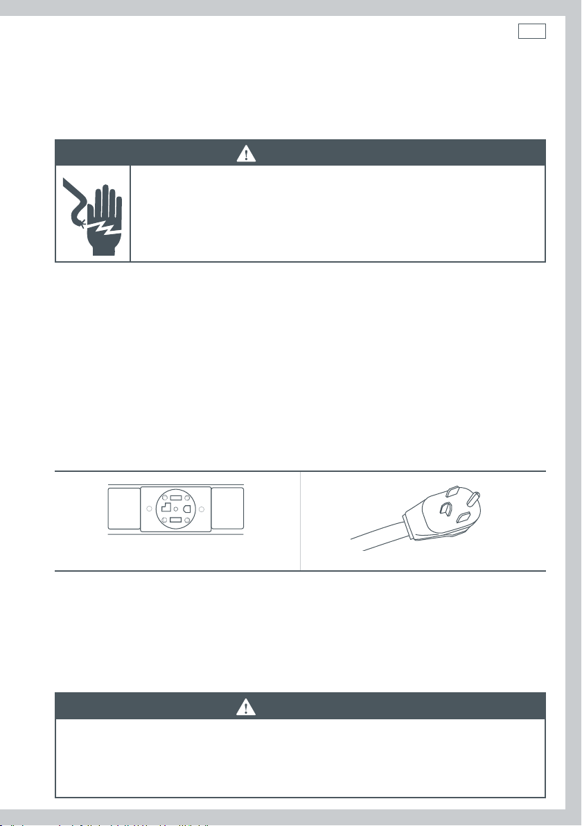
Connecting an electric dryer (skip for gas dryers) – in Canada only
Electrical requirements (electric models only)
WARNING!
Electric Shock Hazard
Plug appliance into grounded 4 prong outlet.
Failure to do so can result in death or electric shock.
Note: the wiring diagram is located in the control console.
It is your responsibility to:
Contact a qualified electrical installer.
Ensure the electrical connection is adequate and conforms with Canadian Electrical Code, C22.1
and all local code requirements.
Plug the dryer into, or connect the dryer to an individual branch circuit, which is protected by
the correct time delay fuses or circuit breakers. The power supply must be a 4-wire, single phase,
120/240 V, 60Hz, 30 amp circuit.
This dryer is supplied with a CSA approved power cord (5 feet (1.52 m) in length, intended for
plugging into a 14-30R wall outlet. Ensure the outlet is within reach of the dryer’s final location.
25
4-wire
(NEMA type 14-30R)
A replacement power cord is available, if required. Use of part number 248C1014G001 (240 V
cord set) is recommended. Contact Fisher & Paykel Customer Care (refer to page 84).
Grounding instructions
This dryer MUST be connected to a grounded metal, permanent wiring system.
WARNING!
Improper connection of the equipment-grounding conductor can result in a risk of
electric shock. Check with a qualified electrician or service representative if you are
in doubt as to whether the appliance is properly grounded. Do not modify the plug
provided with the dryer.

26
Installation instructions
Exhausting the dryer
Refer to page 7 for tools required.
WARNING!
Fire Hazard
The dryer must be vented to the outdoors.
Use rigid or thick wall flexible metal exhaust duct only.
Do not use a plastic exhaust duct.
Do not use a metal foil exhaust duct.
Failure to follow these instructions can result in death or fire.
This dryer must be vented to the outdoors. This will prevent the build up of lint and moisture in
the room in which it is located and reduce the risk of fire.
Use only 4” (102 mm) rigid metal ducting material for the home exhaust duct.
Use only 4” (102 mm) rigid metal or UL-listed flexible metal (semi-rigid or foil-type) duct material
to connect the appliance to the home exhaust duct. The ducting must be installed according to
the instructions found in the section “Connecting the dryer to the house vent” (page 29).
The dryer must not under any circumstances be exhausted into a chimney, a wall, a ceiling, gas
vent, crawl space, attic, under an enclosed floor, or into any concealed space of a building.
Never vent the dryer into a common duct with an exhaust system originating from a kitchen. The
combination of grease and lint creates a potential fire hazard.
Ducting must be kept as short in length and as straight as possible. Ducts can accumulate lint
and create a potential fire hazard. Do not exceed the maximum exhaust duct lengths stated later
in these installation instructions (page 33).
Never install a screen in or over the dryers exhaust duct. The screen will cause lint to accumulate,
creating a potential fire hazard.
Use duct tape to secure joints in the ducting. Do not use screws as these will extend into the
duct system, accumulate lint and create a potential fire hazard.
Never obstruct incoming or exhausted air.
Ensure access is provided for inspection and cleaning of the exhaust. This is particularly
important at turns and joints. The exhaust system shall be inspected and cleaned annually.
The dryer is set up for rear exhausting. If space available for installation is limited, the dryer can
be vented directly from the sides or bottom of the cabinet. Refer to pages 35 to 38.
Installation instructions
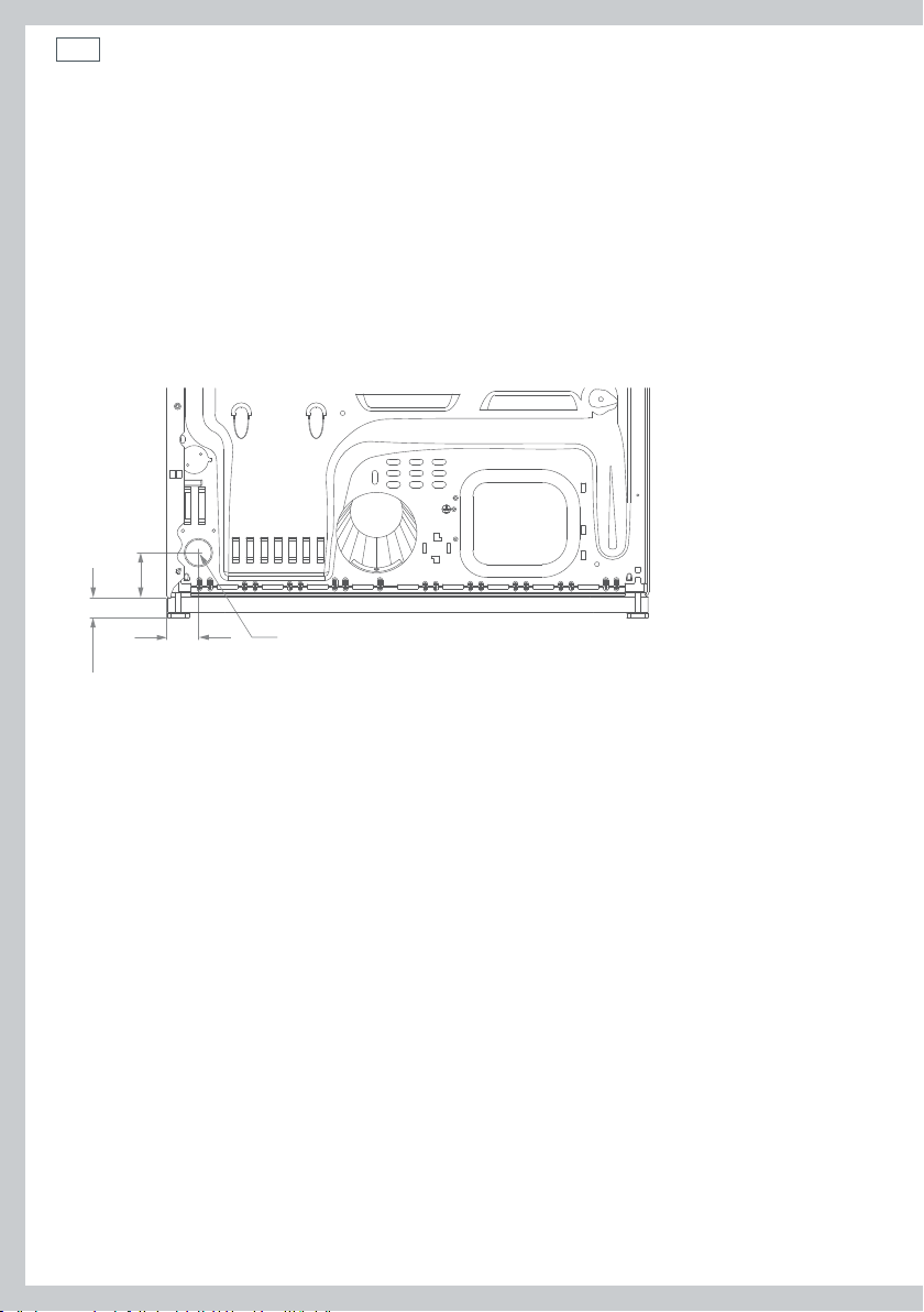
Dimensions
Exhaust outlet location
Exhaust outlet
3 ½” (89 mm)
11 ¾” (298 mm)
Note: add to vertical dimension the
distance between cabinet bottom to floor
Before you start
If required, remove and discard of all existing plastic or metal foil duct. Replace this with
UL-listed duct material.
Check for and remove any lint from the vent opening in the wall.
Ensure the exhaust hood damper moves freely.
Fig.16 Exhaust outlet dimensions
27
Internal duct
opening
Wall
Check that exhaust
hood damper opens
and closes freely
Fig.17 House vent opening

28
Installation instructions
Exhaust system setup
Hood or wall cap
Ensure the exhaust duct ends with a vent hood
with a swing out damper to prevent back drafts
12” min.
(305 mm)
and entry of wildlife.
Ensure there is minimal resistance to the exhaust
airflow. The structure should also require little or
no maintenance to prevent clogging.
Never place a screen in or over the duct.
The vent hood should have at least 12”(305 mm)
clearance between the bottom of the hood and
the ground or other obstruction.
The hood or wall cap should point downward.
Fig.18 Exhaust hood installation
12” min.
(305 mm)
Separation of turns
Separate all turns by at least 4 feet (1.2 m) of straight ducting (including the distance between
the last turn and the wall cap) to ensure the best performance of the dryer.
Turns other than 90°
One turn of 45° or less may be ignored.
Two 45° turns are to be considered equal to one 90° turn.
Each turn greater than 45° should be considered as equal to one 90° turn.
Important!
Choose a route that will provide the straightest and most direct path to the outdoors. Plan the
installation to use the fewest number of elbows and turns as possible.
When using elbows (rigid duct) or making turns (thick wall flexible metal duct), allow as much
room as possible. Bend thick wall flexible metal duct gradually to avoid kinking, and avoid
90°turns using this material.
Recommended Acceptable
Fig.19 Duct configurations

Installation instructions
Sealing of joints
All joints must be tightly sealed to avoid leaks.
The male end of each section of duct must be installed away from the dryer.
Do not use screws or fasteners that extend into the duct to secure the joint as lint will
accumulate around these, creating a potential fire hazard.
Joints should be made air- and moisture-tight by securing the overlapped joints with duct tape,
or aluminum tape.
Horizontal duct runs should slope down towards the outdoors ¼” (6 mm) per foot.
Insulation
Ducting that is directed through an unheated area or is near air conditioning should be insulated
in order to reduce condensation and lint build-up.
Connecting the dryer to the house vent
Rigid metal duct
The use of a rigid metal ducting is recommended for best drying performance.
The risk of crushing and kinking of the duct is reduced when using this duct material.
UL-listed flexible metal (semi-rigid) transition duct
If rigid metal duct is not appropriate, a UL-approved flexible metal (semi-rigid) duct material can
be used (kit WC572D559P006).
Do not install flexible metal duct in walls, ceilings, floors or other enclosed spaces.
Flexible metal duct should not exceed 8 feet (2.4 m) in total.
Installing elbows at both the dryer and the wall is highly recommended. An elbow allows the
dryer to be positioned close to the wall without kinking and/or crushing the transition duct, and
maximizes the performance of the dryer.
Do not rest the ducting on sharp materials and objects.
29

30
Installation instructions
UL-listed flexible metal (foil-type) transition duct
Connecting the dryer to the house vent using flexible metal (foil-type) duct maybe required in
some installations. A UL-listed flexible metal (foil-type) duct can ONLY be used where:
rigid metal or flexible metal (semi-rigid) ducting cannot be used, AND
a 4” (102 mm) diameter can be maintained throughout the entire length of the transition duct.
Only flexible metal (foil-type) ducts that comply with the requirements of the “Outline for
Clothes Dryer Transition Duct Subject UL2158A”, shall be used in the United States and Canada.
Do not install flexible metal duct in walls, ceilings, floors or other enclosed spaces.
Flexible metal duct shall not exceed 8 feet (2.4 m) in total.
Do not rest the ducting on sharp materials and objects.
To ensure the best performance of flexible metal (semi-rigid and foil type) transition duct:
1
Slide one end of the duct over the exhaust outlet pipe at the back of the dryer.
2
Secure the duct to the pipe with a clamp.
3
Move the dryer to its final position.
4
Extend the duct to its full length. Allow 2” (51 mm) of duct to overlap the house exhaust
outlet pipe. Cut off and remove the unwanted duct. Keep the duct as straight as possible for
maximum airflow.
5
Secure the duct to the house exhaust outlet pipe with a clamp.

For transition venting (dryer to wall):
DO:
Installation instructions
Elbows
31
DO cut duct as short as possible
and install straight into wall
Fig.20 Correct venting installation
DO NOT:
DO NOT bend or collapse ducting
Use elbows if turns are necessary
DO use elbows when turns
are necessary
DO NOT use excessive exhaust length
Cut duct as short as possible
DO NOT crush duct against the wall DO NOT set dryer on duct
Fig.21 Dangerous venting installation set ups

32
Installation instructions
Exhaust Length
Maximum length of exhaust duct
The maximum length of the exhaust duct system depends upon:
The type of ducts used (rigid or thick-walled flexible metal).
The number of elbows or bends used.
The type of exhaust hood (wall cap).
1
Refer to the exhaust duct length chart (page 33) that matches your hood type to determine
the maximum duct lengths you can use. DO NOT use duct lengths longer than specified in the
exhaust duct length charts.
Using exhaust duct systems longer than is specified will:
Accumulate lint creating a potential fire hazard.
Shorten the life of the dryer.
Reduce the performance, resulting in longer drying times and an increased energy usage.
2
Determine the number of elbows/bends you will need.
3
In the column listing the type of metal duct you are using (rigid or flexible metal), find the
maximum length of metal duct on the same line as the number of elbows/bends to be used
(refer to page 33).
Important!
Use 4” (102 mm) metal duct only.
Do not use duct that is longer than that specified in the table on page 33.
Flexible metal duct shall not exceed 8 feet (2.4 m) in total.
The correct exhaust installation is YOUR RESPONSIBILITY.
Problems due to incorrect installation are not covered by the limited warranty.
WARNING!
Incorrect installation of the exhaust duct may result in poor dryer performance and
increase the risk of fire.

Installation instructions
Preferred 4” (102 mm) Hoods
33
4” Dia (102 mm)
4” (102 mm)
When you have a 4” (102 mm) Hood
Maximum length of 4” (102 mm) diameter metal duct.
Number of 90˚
elbows/bends
0 90 ft 27.4 m 8 ft 2.4 m
1 60 ft 18.3 m 8 ft 2.4 m
2 45 ft 13.7 m 8 ft 2.4 m
3 35 ft 10.7 m 8 ft 2.4 m
4 25 ft 7.6 m 8 ft 2.4 m
Rigid metal
4” Dia (102 mm)
Flexible metal
(fully extended)
Acceptable 2 ½” (64 mm) Hood (for short length installations)
4” Dia (102 mm)
2 ½” (64 mm)
When you have a 2 ½” (64 mm) Hood
Maximum length of 4” (102 mm) diameter metal duct.
Number of 90˚
elbows/bends
0 60 ft 18.3 m 8 ft 2.4 m
1 45 ft 13.7 m 8 ft 2.4 m
2 35 ft 10.7 m 8 ft 2.4 m
3 25 ft 7.6 m 8 ft 2.4 m
4 15 ft 4.6 m 8 ft 2.4 m
Rigid
Flexible Metal
(fully extended)
34
Installation instructions
Standard rear exhaust
We strongly recommend the use of rigid metal exhaust duct. We recommend you install your dryer
first, before installing your washer. This will allow you easier access for connecting the exhaust.
Place the end of the exhaust duct on the outlet at the rear of the dryer. Secure with duct tape or
a hosed clamp. For a straight installation, connect the dryer exhaust directly to the wall. Use duct
tape to secure the join.
Wall side
Duct
Dryer side
Fig.22 Attaching the metal duct to the dryer outlet
Fig.23 Securing the duct join with duct tape

Installation instructions
Dryer exhaust to right, left or bottom of cabinet
WARNING!
Before performing this exhaust installation, be sure to disconnect the dryer from its
electrical supply. Protect your hands and arms from sharp edges when working inside
the cabinet. Be sure to wear gloves.
Important!
Dryer exhaust to right of cabinet (electric models only).
Dryer exhaust to left of cabinet (gas and electric models).
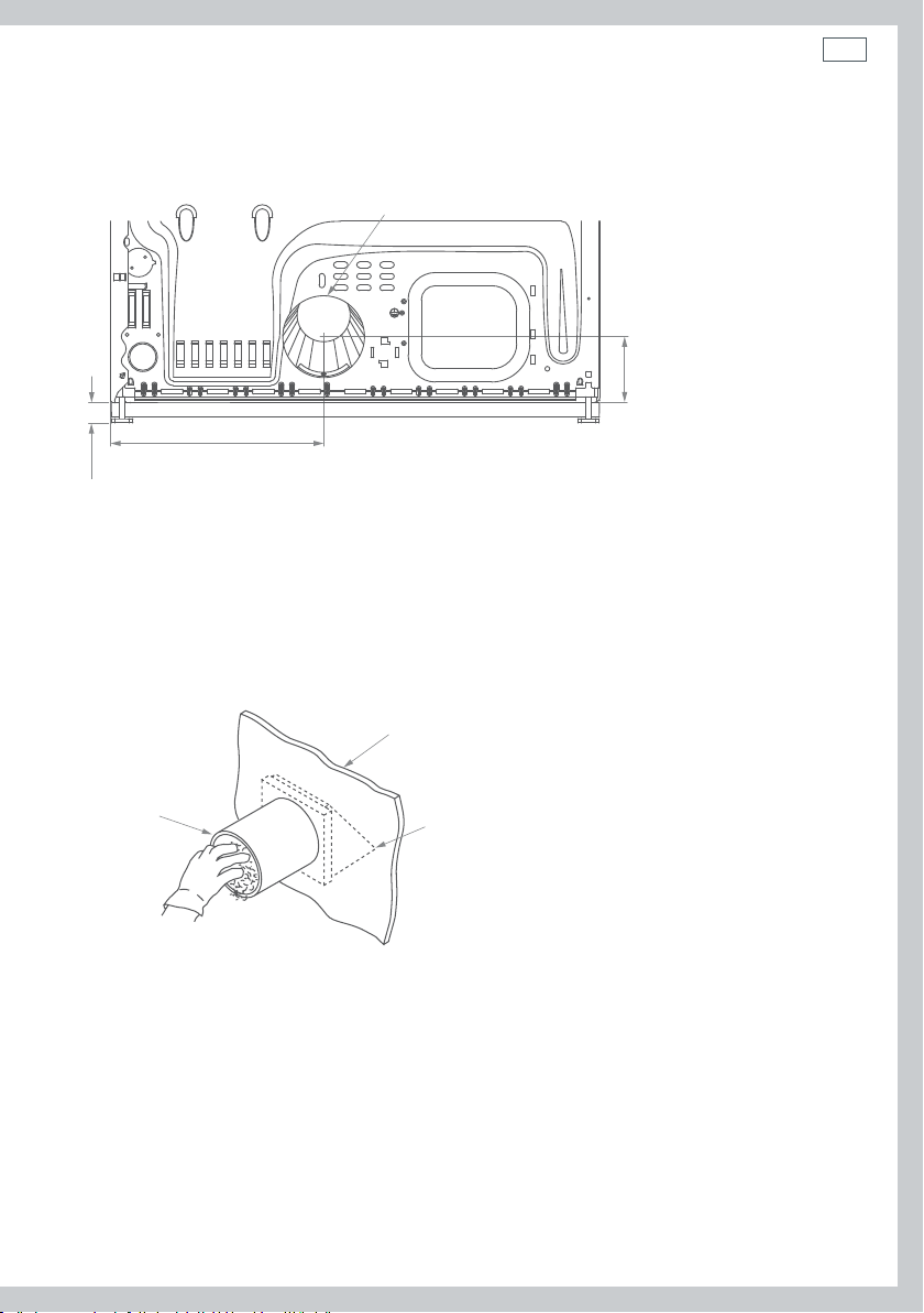
Detach and remove the bottom, right or left side knockout (the opening for alternate ducting),
as preferred for the direction of ducting. Tape around the knockout and exhaust opening to
provide protection from sharp edges during installation. Remove the screw inside the dryer
exhaust duct and slide the duct out of the dryer. Keep the screw. Cut the duct as shown in
Figure24. Retain portion A of the duct.
Right (electric
models only)
Fixing hole
35
Remove screw
and save
Bottom (gas
and electric
models)
Left (gas and
electric models)
Remove desired
knockout (one only)
Fig.24 Removing and
shortening the duct
9” (230 mm)
Tab location
Through the rear opening, find the tab located in the middle of the dryer base. Using a flat blade
screwdriver, lift the tab to approximately 45°.
Bend tab
up 45°
Fig.25 Lifting the tab

36
Installation instructions
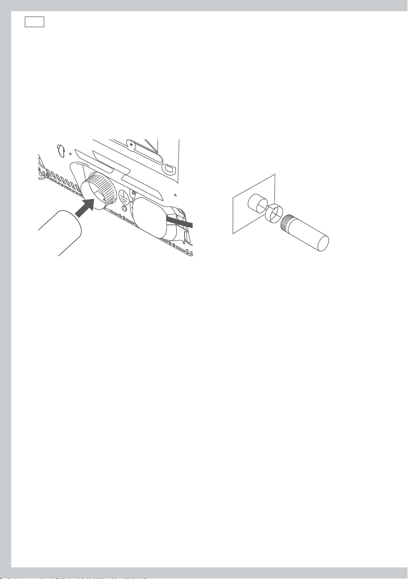
Adding shortened duct section
Connect portion “A” of the original length of duct to the blower housing, ensuring the shortened
duct is aligned with the tab in the base. Use the screw saved previously to secure the duct in
place through the tab on the dryer base.
Fixing
hole
Portion “A”
Side exhaust
Fig.26 Installing shortened duct section

Installation instructions
Adding ducting for exhaust to the right or left side of the cabinet
Assemble a 4” (102 mm) elbow with a 4” (102 mm) length of duct. Secure the joint with duct tape.
Insert the elbow end of the duct assembly carefully through the side opening, and connect this
end to the internal duct of the dryer (inside).
WARNING!
Be sure not to pull or damage the electrical wires inside the dryer when inserting the duct.
Internal duct joints must be secured with tape, otherwise they may separate and cause
a safety hazard.
Exhaust can be added
to the left (gas or electric
models) or right side (electric
models only)
Duct tape
Fig.27 Left and right exhausting
Use duct tape (as shown in Figure 28) to secure the joint between the dryer internal duct and the
elbow, and also the joint between the elbow and the side duct.
37
Duct tape
Fig.28 Securing joints correctly with duct tape
Cover the original duct opening at the back with a plate (kit WE1M454), available from Fisher &
Paykel, refer to page 84).
Fig.29 Cover plate

38
Installation instructions
Adding elbow for exhaust through bottom of cabinet
Insert the elbow section of the duct through the rear opening and connect it to the dryer
internal duct.
Secure the joint between the internal duct and elbow with duct tape, as shown in Figure28
(page37).
Fig.30 Exhaust elbow
Complete the exhaust system by connecting the required standard metal elbows and ducts.
Cover the original duct opening at the back with a plate (kit WE1M454, available from Fisher &
Paykel (refer to page 84). Refer to Figure 29 (page 37).
Move the dryer into its final position.
WARNING!
The rear duct opening must be covered with a plate. The dryer must not be operated
without the plate in place.

Installation instructions
39
Water connection (for selected models with Steam cycles)
Supply requirements
The hot and cold faucets MUST be installed no further than 42” (1070 mm) from the washer’s
inlet supply. Faucets need to be ¾” (19 mm) so the inlet hoses can be connected correctly.
Inlet water pressure required: Min. 10 psi (70 kPa) to Max. 120 psi (827 kPa). Consult your Water
Department for information about the pressure supplied to your home.
Note: if your domestic water supply is hard, we recommend using a water softener to help
reduce the build up of lime scale within the steam generator. Over time, a build up of lime scale
may block up the water system, causing reduced performance and the possible need for part
repair or replacement.
Water supply connection
For the Steam cycles to work correctly, the dryer must be connected to the cold water supply. A
“Y” connector can be used so that the washer (which also requires a cold water supply) and dryer
can be connected to the cold supply at the same faucet.
Important!
Use the new inlet hoses provided with your dryer. Never reuse old hoses or rubber washers.
Inlet hose replacement
We recommend the inlet hoses are changed every 5 years. Hoses should also be checked from
time to time and replaced if any wear, cuts, bulges, kinks or leaks are found. WARNING!: Failure to
do so may result in a flood and damage to property.
To connect the dryer
Parts required:
Flat rubber washers(4).
Filter washer.
“Y” connector.
Short inlet hose.
Long inlet hose.
1
Ensure the cold faucet is turned off. Disconnect
the cold inlet hose from the end of the faucet.
2
Insert the filter washer into the female coupling
of the short inlet hose and connect it to the
cold faucet.
3
Insert a flat washer into the female coupling of
the “Y” connector and fit the connector to the
male coupling of the short inlet hose.
Long inlet hose
“Y” connector
Flat rubber
washer(s)
Filter washer
Filter washer
Short inlet hose
Fig.31 “Y” Connector
40
Installation instructions
4
Check that the washer inlet hose (which has been removed from the faucet) has a flat washer or
filter washer fitted. If not insert a flat washer and connect the hose to one of the male couplings
on the “Y” connector.
5
Take the long inlet hose and insert a flat washer into the straight female coupling and connect it
to the other male coupling on the “Y” connector.
6
Insert a flat rubber washer into the other female connector and couple the hose to the inlet
valve on the rear of the dryer.
Fig.32 Attaching the inlet hose to the dryer
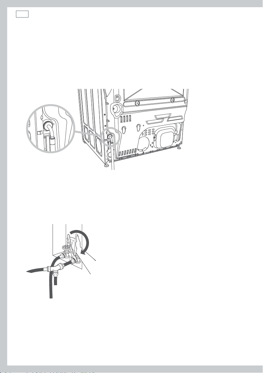
7
Check that all connections are firmly hand tight, then using a pair of pliers tighten each coupling
another two-thirds of a turn.
Important!
Ensure you DO NOT OVERTIGHTEN the connections. Overtightening may result in damage to the
couplings.
Fig.33 Tightening the connections
8
Check immediately for any leaks from the “Y” connector, hose couplings and/or the faucet. Check
again for leaks after 24 hours.

Installation instructions
Reversing the door
Tools required:
Standard #2 Phillips screwdriver.
Tape-tipped putty knife.
Needle-nosed pliers.
1
Remove the plug from the power outlet.
2
Open the door and remove the blanking plugs opposite the hinges. Retain the blanking plugs
for Step 4.
3
With the door completely open, remove the bottom screw from each hinge on the dryer face.
Insert these screws about half way into the top holes, for each hinge, on the opposite side
(where you removed the plastic plugs). Apply firm pressure to get the screw started in untapped
holes.
41
Fig.34 Removing the door
4
Loosen the top screw from each hinge on the dryer face to half way. With one hand holding
the top of the door and the other hand holding the bottom, remove the door from the dryer by
lifting it up and out. Remove the two remaining screws and retain for later use. Fit the blanking
plugs removed in Step 2.

42
Installation instructions
5
To invert the direction of the door panel, lay the door face down on a safe, protected surface and
remove the four screws from the hinges.
Fig.35 Removing screws from the hinges
6
Separate the door panel from the inside of the door by removing the six screws, as shown in
Figure 36.
Fig.36 Separating door panel from inside of door
Important!
Remove only the six screws as shown.
7
Lift and rotate the door panel 180º then reinsert the inside of the door in the panel. Replace the
six screws removed in Step 6.
Fig.37 Rotating door panel, then replacing screws

Installation instructions
8
Reattach the hinges on the opposite side to the door handle, using the same four screws on the
hinge retained from removing the hinges in Step 5.
Fig.38 Fixing hinges to opposite side
Important!
Check the position of the hinge as shown in Figure 38.
9
To change the direction of the door strikes, unscrew both the cover plate and the strike plate
(the strike plate being the plate with the metal part protruding). Reinstall one plate in place of
the other.
43
Fig.39 Exchanging cover plate and strike plate location
10
Install the door on the opposite side of the opening by moving the door in and down until the
top hinge and bottom hinge are resting on the two screws inserted in Step 3. With the two
screws retained in Step 4, secure each hinge at the bottom.
Fig.40 Installing the door in the reverse position
11
Tighten the two top screws of each hinge.

44
Installation instructions
Leveling the dryer
Position the dryer near the final location. Adjust the four leveling legs (wind up or down) at the
corners as needed, to ensure the dryer matches the height of the washer and is level from side to
side and front to back. The dryer must rest firmly on all four legs, and not rock in any direction.
1
Move the dryer to its final location.
2
To ensure the dryer is correctly level from side-to-side, place a spirit level on the top center of
the machine. If level, the air bubble will sit between the two lines.
3
To check whether the dryer is correctly level from front-to-back, open the door to the 90°
position, place the spirit level on the top edge of the door and check the bubble sits between
the two lines.
4
If the dryer is not level in any direction, adjust the height of the appropriate leg(s) until the dryer
is correctly level.
Level side-to-side
Level front-to-back
4 leveling feet
Fig.41 Leveling the machine
Installation instructions
Installation checklist
1. Packaging
Have all of the packaging materials been removed, and disposed of responsibly? Remove the
accessories from the drum.
2. Parts
Check that all parts have been installed.
3. Tools
Check all tools are present.
4. Grounding
Important!
Make sure the dryer is correctly grounded before operating.
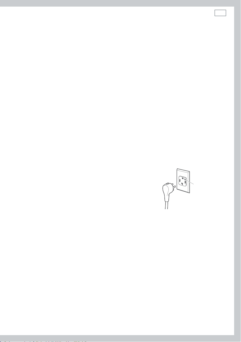
45
This appliance must be grounded. In the event of malfunction
or breakdown, grounding will reduce the risk of electric shock
by providing a path of least resistance for electric current.
This appliance is equipped with a cord having an equipmentgrounding conductor and a grounding plug. The plug must be
plugged into an appropriate outlet that is properly installed and
grounded in accordance with all local codes and ordinances.
Fig.42 Ensure outlet is grounded
correctly before use
Ensure proper
ground exists
before use
5. Installation
Please ensure:
No plastic or non-UL listed flexible metal foil material has been used for the exhaust ducting.
Exhaust material used is either rigid ducting or thick wall flexible metal ducting.
All joints in the ducting are secured with duct tape, as described in the instructions. Screws or
other fastening devices which extend into the inside of the duct should not be used.
Ducting system is clean and is correctly and securely connected to the dryer.
The ducting system is not being crushed or kinked when the dryer is in its final position.
The faucets are turned on. Check for leaks around the connections (at the Y connector, hoses
and faucets).
The dryer is correctly level and does not rock in any direction.
The inside of the drum is wiped out with a damp cloth to remove any residue remaining from
manufacture or installation, before use.

46
Installation instructions
Additionally for electric dryer models only, check:
Dryer is plugged or directly wired into an approved fitting, and is properly grounded.
Dryer starts, heats, cools and shuts off.
Customer has been shown how to use the dryer.
Additionally for gas dryer models only, check:
Dryer is plugged into an approved fitting, and is properly grounded.
All fittings in the gas line have been tested for leaks.
Exhaust temperature increases, to confirm ignition has occurred.
– If ignition does not occur initially, it may be due to air in the gas line or low voltage power supply.
– The gas regulator valve may fail to open if the power supply falls below 105 Volts.
– If the gas fails to flow or does not ignite, the dryer will automatically switch off.
Customer has been shown how to use the dryer.
6. Turning the dryer on
To turn the dryer on, simply touch the POWER button.
Note: if the dryer has been exposed to temperatures below freezing for
an extended period of time, allow it to warm up before touching POWER.
Otherwise, the display will not come on.
If the dryer will not start, check that:
The START/PAUSE button has been pressed firmly.
The dryer is plugged in and the power is turned on. Could the household supply be at fault?
The household fuse is intact and that the circuit breaker has not been tripped.
The dryer door is completely closed.
Note: some models of dryer have a drum reversal feature to reduce clothes tangle. Throughout
the drying cycle the motor will run for 4 minutes, then stop and run in the opposite direction for
40 seconds before reversing again.
The dryer may emit an odor when it is first used. This is due to the new heating element, and is
normal. The odor will diminish with the use of the dryer.
Important!
Please read the user guide in its entirety and familiarize yourself with the correct use and care of
the dryer.

Installation instructions
Servicing
Important!
Label all wires prior to disconnection when servicing controls. Wiring errors can cause improper
and dangerous operation after servicing/installation.
For service and other information, refer to the “How to get service” section in the back of this
book (refer to page 84).
Drum light replacement
Before replacing the light bulb, be sure to unplug the
dryer power cord or disconnect the dryer at the household
distribution panel by removing the fuse or switching off
the circuit breaker. Reach inside, above the dryer opening
inside the drum. Remove the bulb and replace with the
same size bulb.
Fig.43 Drum light
47

48
The first time you turn your dryer on
Remove the protective tape from the control panel.
WARNING!
Electric Shock Hazard
To reduce the risk of fire, electric shock, or injury to persons, read and
follow the IMPORTANT SAFETY INSTRUCTIONS outlined in this User
Guide before operating this appliance, pages 3 – 6.
Failure to do so can result in death, electric shock, fire or injury to
persons.
Features
Perfect with the Fisher & Paykel AquaSmart™ washer
The dryer combined with the AquaSmart™ washer’s superior spin performance and quick cycle
times will cut laundry turn around time, reducing the time you spend doing laundry.
Superior clothes care
Superior clothes care is accomplished by an efficient high airflow fan and careful heat control.
Your AeroCare dryer provides the right heat for temperature-sensitive delicate garments while
still efficiently drying more robust regular and denim loads.
Reverse action tumbling (selected models only)
You can select to have the drum rotate in the reverse direction regularly, so your clothes dry
more evenly and roping and tangling of garments is minimized.
Autosensing
AeroCare’s internal computer measures the moisture content of the load using metal sensing
bars and together with a temperature sensor determines when the clothes have reached the
selected dryness level.
Steam cycles (selected models only)
Two cycles, AEROSTEAM and AEROSTEAM PLUS use pulses of steam to de-wrinkle items and/or
freshen your garments from unpleasant odors or after prolonged storage.
Stainless steel drum
AeroCare’s stainless steel drum is not only more hygienic, it’s also more resilient and is easier to
keep looking good.

The first time you turn your dryer on
Wrinkle Free
Use WRINKLE FREE to minimize wrinkling and creasing in your garments. After the clothes are
dried, they will be tumbled periodically in cool air. WRINKLE FREE will continue for 24 hours or
until the dryer is stopped by pressing POWER, or opening the door.
WRINKLE FREE can be selected if you are using one of the automatic cycles (excluding the
ENERGY SAVER cycle), and on the TIME DRY cycle.
Drum light
A convenient light located inside the dryer helps make unloading easier. The light switches on
automatically when the door is opened.
For drum light replacement, please refer to page 47.
Drying rack
The drying rack can be used for drying articles such as soft toys,
pillows, washable sweaters and shoes, ie items that are too
delicate or maybe damaged by tumbling. Place (hook) the rack
over the lint filter so that it extends back into the drum.
Note: the drying rack should be used with the RACK DRY or
TIMEDRY cycles only. Also, the drying rack should not be used
when there are other items in the dryer as this may cause
damage to the garments.
Fig.44 Drying rack
49

50
Getting started quickly
Ensure the lint filter has been cleaned before each drying cycle. Check the lint filter has been
replaced correctly in its housing before using your dryer.
Sort and load items into the dryer drum. Ensure that no items are caught in the way of the door,
then close the door. Check the door is fully closed before starting the dryer.
Important!
Ensure there is plenty of room for the garments to tumble freely while drying – do not overload
your dryer. Load in terms of the space clothes take up when dry rather than when they are wet.
1
Press POWER to activate your dryer.
2
Your dryer will default to the REGULAR cycle. Select your desired drying cycle by turning the
SmartTouch™ Control Dial.
3
Select your preferred drying options (if you wish to select different options from the default options
programmed for the cycle) using the SmartTouch™ buttons on the right hand side of the panel.
4
Touch the START/PAUSE button to start the drying cycle.
Fig.45 AeroCare control panel (models may vary)
Note: the control panel may differ depending on what model of dryer you have.
21

Getting started quickly
If you make an invalid selection the dryer will beep to alert you.
When the cycle finishes, your dryer will beep to alert you and then turn off automatically. If the
WRINKLE FREE option has been selected the machine will rotate the drum periodically after the
end of the cycle, blowing cool air into the drum to help minimize wrinkling of the clothes.
If you wish to stop your dryer at any point during a cycle simply touch START/PAUSE to pause the
cycle, then open the door. To restart the dryer, close the door and touch START/PAUSE to resume
the cycle.
If you wish to cancel a cycle or select a different option once a drying cycle has started, touch
the START/PAUSE button then select the new cycle or option. Touch START/PAUSE to restart the
dryer with the new settings.
Important!
If you wish to stop the dryer before the cycle has finished you MUST remove the clothes
IMMEDIATELY and spread them out to cool. DO NOT leave the clothes in the dryer or bunched
up in a clothes basket, these must be spread out in order for the heat to dissipate. There is a risk
of spontaneous combustion. Take extreme care when removing items as the drum and the load
items may be extremely hot.
51
43
Important!
Failure to follow the advice in this guide may result in damage to your garments and your
expectations of drying performance may not be met.
Note: selected drying cycles and options may not be available depending on your model of dryer.

52
AeroCare controls
SmartTouch™ Control Dial
The SmartTouch™ Control Dial provides easy and efficient drying cycle selection. As you rotate
the dial, the icon of the drying cycle selected will be illuminated, along with the default settings
for that cycle on the right side of the control panel.
SmartTouch™ buttons
The smooth, easy clean buttons enable simple selection of options with lights clearly showing
the selections you are making.
Digital display screen
The digital display screen provides feedback on how long the drying cycle has to go. If you have
programmed a DELAY START, the time remaining until the cycle will start will be displayed here,
along with any messages to help you with the overall running of your dryer (eg user warnings).
Time to go
Your AeroCare dryer displays approximately how many minutes the cycle has remaining, so
that you can tell at a glance when your drying will be finished. Please be aware that a number
of factors influence the overall cycle time, eg the fabric type, load size, the wetness of the load,
environmental conditions, etc. If the dryer display screen shows a dashed line tracing around the
outside of the screen, this indicates the dryer is sensing the moisture in the load. The updated
time remaining will soon appear on the screen.
Progress lights
The progress lights indicate what part of the cycle the dryer is currently up to (DAMP, DRY, or
COOLING). The light for the current part of the cycle flashes, to let you know at a glance how dry
your load is.

AeroCare controls
Keylock
Keylock can be used to deactivate the buttons on your AeroCare dryer when it is in use. This
will avoid accidental button touches from items left on top of the dryer (eg washing baskets,
clothing) as well as touches from any little fingers.
To turn Keylock ON or OFF:
Touch and hold the KEYLOCK button for two seconds.
Note: when activated, the light above the KEYLOCK button is illuminated.
If Keylock is activated:
To turn your dryer on, touch and hold the POWER button for two seconds. This will activate the
control panel. Keylock will remain activated but let you select your drying cycle options and start
the cycle.
To PAUSE your dryer at any time during the cycle, touch and hold the START/PAUSE button for
two seconds.
To STOP your dryer and power off, simply touch the POWER button.
53

54
Sorting and loading
When preparing your load there are some important things to consider:
Sorting
Check the fabric care labels on the inside of garments to determine whether the item is suitable
for tumble drying.
It is best that you sort your garments into loads of similar items, and loads that take similar times
to dry, before placing them in the dryer. Heavier items (eg towels, t-shirts and sheets) are best
dried separately from lightweight items (eg synthetics and shirts). This prevents the possibility of
some garments becoming over-dried whilst others are still damp. It will also help to extend the
life of your clothing and linen.
Drying your clothes as soon as you remove them from the washer will reduce the chance of
wrinkles occurring and the chance of dye transfer from colored items to white items.
We recommend that articles of clothing with screen-printing are turned inside out to minimize
damage to the print. Garments with hooks or zippers should be fastened and where possible
turned inside out.
Use the drying rack to dry garments and items that could be damaged by tumbling or you do
not wish to tumble, eg woolen garments, shoes, toys.
Before you load
Check pockets for items that could damage your clothes or get caught in the dryer.
Close zippers, hooks and eyes, and other fastenings (ie fasten the openings of comforter covers),
and remove loose bra wires. These may damage both your dryer and your clothes.
Check the lint filter is clean.
To reduce wrinkling
Shake clothes out and load individually to help items dry evenly.
Launder “permanent press” garments separately, eg business shirts.
Allow enough room in the dryer for clothes to tumble freely.
Use the WRINKLE FREE option.
Hang garments as soon as the dryer cycle is complete to reduce the need for ironing.
Loading
Garments need to be loaded correctly to minimize creasing and wrinkling, and to ensure the
load is dried evenly. Ensure there is plenty of room for the garments to tumble freely while
drying. Load in terms of the space the garments take up when dry, rather than when they are wet.
The general rule is that one wash load equals one dryer load. Do not overload your dryer, as it
may damage your dryer and clothes.
It is a good idea to dry “permanent press” type garments together on a separate cycle with
the WRINKLE FREE option turned on (the EASY IRON has the WRINKLE FREE option turned on
automatically if you use the default settings). This will help reduce wrinkling and creasing and
the need for ironing.

Sorting and loading
Important!
Do not overload your dryer beyond its rated capacity.
Never put dripping wet clothes in or on top of the dryer as excess water may cause an electrical hazard.
Do not under any circumstances dry an electric blanket or any other electrical, plastic or rubber
item on a drying cycle with heat in your AeroCare dryer, unless the care label specifically states it is
safe to do so. Only dry on the AIR DRY cycle.
Do not dry curtains in your dryer. Sunlight makes them brittle and they may disintegrate during drying.
Drying times
Drying very small loads is inefficient. Try to dry medium to large loads.
Heavier items (jeans, sweatshirts) will take longer to dry than light items (synthetics, shirts).
Spin clothes at the highest spin speed suitable for the load type. The more water you remove in the
wash, the less drying time required.
Care labels on garments provide valuable information about the fabric type and how the garment
should be dried. Always follow the advice on the garment labels. Only dry items in this dryer that
have a care label stating tumble drying is suitable.
Separate colored items from whites where possible, especially when new. Color run may be an
issue especially if you intend to delay the start of the drying cycle.
Lint
55
Some items are lint givers, while others are lint collectors. Always dry lint givers and collectors
separately.
Lint givers Lint collectors
Towels Synthetics
Flannel Socks
Nappies Polyester cottons
Delicate or easily damaged items (ie woolen or silk garments, nylon stockings, fine fabrics, delicate
embroidered fabrics, garments with metal accessories) should be dried separately using the DELICATE
cycle or the RACK DRY cycle (if you do not want them tumbled).
Lint filter
Before you start your dryer you need to ensure the lint filter has
been cleaned. AeroCare will flash the “Clean Lint Filter” signal light
on the panel (above the START/PAUSE button) every time you turn
your dryer on to remind you to clean the lint filter.
Important!
It is important that you run your dryer with the lint filter in place AT ALL TIMES.
Fig.46 Clean lint filter signal light
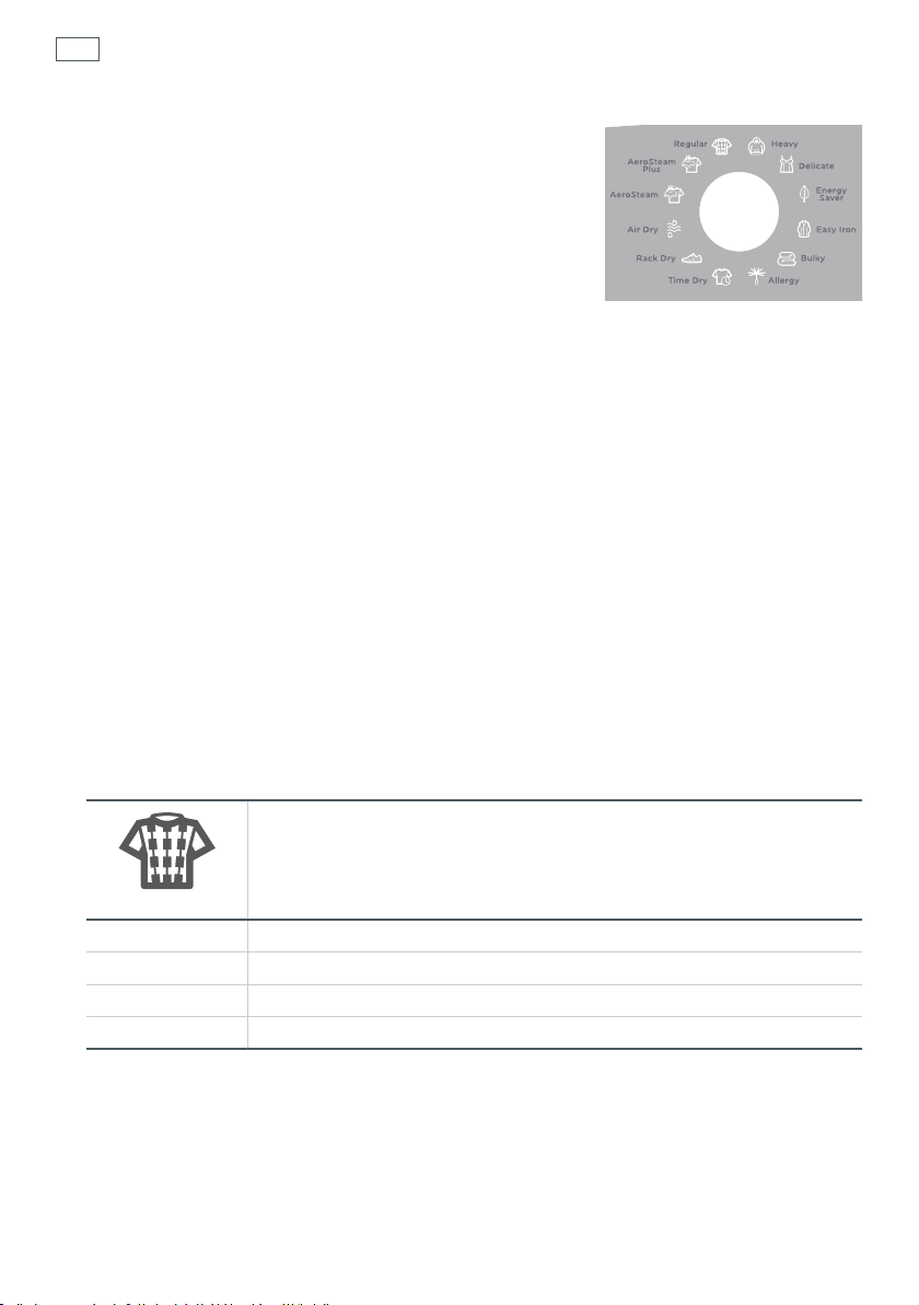
56
Dryer cycles
Your dryer has a number of DRYING CYCLES that can be used
to dry different types of garments:
All drying cycles default to the recommended options for
that cycle based on the average expected load to be dried
using that cycle. You can vary the options (egDRYNESS
LEVEL, DRYING TEMP) to create your desired cycle. Refer to
page70.
Note: some options are not available on some cycles,
for clothes care reasons, or because the option is not
appropriate for the cycle.
To change a drying cycle or options you have selected after a cycle has started, touch START/
PAUSE and select your new cycle and or settings, then touch START/PAUSE again to resume the
cycle with the new setting(s). Some options may not be available for selection under certain
conditions and after particular stages of the cycle have passed.
Always follow manufacturer’s care label instructions when drying your garments. If you are
unsure of the temperature to select for a load, it’s best to select a cycle with a lower rather than a
higher temperature, eg the DELICATE or EASY IRON cycle instead of the REGULAR cycle.
When drying casual, everyday garments we recommend using the EASY IRON cycle (with DRY
drying temp selected). If this cycle is not offered on your model of dryer, use the DELICATE cycle.
Fig.47 Drying cycles
Note: not all cycles may be available
on your model of dryer
Note: not all cycles and options may be available on your model of dryer. Default cycle settings
are shown.
Regular
A high heat cycle for rapid drying of everyday cottons. This cycle is
suitable for most garments labelled “Tumble Dry”.
Regular
Dryness Level Dry
Drying Temp High
Wrinkle Free Off
Drum Reverse On

Heavy
An extended, high heat cycle designed for heavy fabrics and denims to
ensure thick and bulky seams are thoroughly dried.
Heavy
Dryness Level Dry
Drying Temp High
Wrinkle Free Off
Drum Reverse On
Delicate
Extra care for delicate, heat sensitive items or fabrics recommending low
heat. Also recommended for casual garments.
Delicate
Dryness Level Dry
Drying Temp Low
Wrinkle Free Off
Drum Reverse On
Dryer cycles
57
Energy Saver (selected models only)
An extended cycle with periods of no heating, reducing overall energy
consumption.
Energy Saver
Dryness Level Dry
Drying Temp Low
Wrinkle Free Off
Drum Reverse On
Easy Iron (selected models only)
A medium heat cycle with WRINKLE FREE option, for extra care and to
minimize wrinkles forming. Ideal for any garments that you may wish to
Easy Iron
Dryness Level Damp Dry
Drying Temp Medium
Wrinkle Free On
Drum Reverse On
Note: fasten buttons before placing shirts in the dryer.
wear immediately (eg casual items).
58
Dryer cycles
Bulky
A specialized cycle to care for bulky items, eg blankets, jackets, comforters.
Bulky
Dryness Level Dry
Drying Temp Medium
Wrinkle Free Off
Drum Reverse On
The BULKY cycle takes special care of bulky items. Bulky garments and bedding dry most
effectively when they can move freely. Ensure that there is sufficient room in the drum for the
load to move during drying.
For all bulky items:
It is important that you check the care label of any item carefully, to ensure it is suitable for
tumble-drying, before placing it into the dryer.
Check bulky items during the cycle to ensure even drying. Reposition if necessary. For items
containing down or feathers, place a damp towel tied in a knot in the dryer along with the item
to help fluff the feathers.
When drying a single bulky item or blanket include 4 – 5 medium sized towels to provide
cushioning. This will help to keep the item moving throughout the cycle.
Important!
Dry bulky items thoroughly to prevent mildew from forming.
Allergy
A high temperature cycle to eliminate dust, mites and bacteria.
Allergy
Dryness Level Extra Dry
Drying Temp High
Wrinkle Free Off
Drum Reverse On
Note: the ALLERGY cycle is not recommended for garments prone to shrinkage or susceptible to
heat damage (eg synthetics). Check the garments care label.

Dryer cycles
Time Dry
For clothes that you only want dried for a specific time period. A high heat
cycle where the time can be adjusted using the MORE
Time Dry
Dryness Level n/a*
Drying Temp High
Wrinkle Free Off
Drum Reverse On
Note: the dryer dries for the selected time regardless of the level of moisture in your clothes. It
is important to check your items throughout a TIME DRY cycle to avoid over-drying. The time
includes a 5 minute cool down period at the end of the cycle.
We recommend that you dry your clothes for a slightly shorter time than you think they need, or
check on them regularly (to avoid over-drying).
Rack Dry
Dryness Level n/a*
Drying Temp Medium
Wrinkle Free Off
Drum Reverse Off
buttons.
Rack Dry
Specifically for use with the drying rack so you can dry items flat without
them tumbling. eg shoes, hats, delicate jerseys. A 40 minute cycle with no
heat. Cycle time can be adjusted using the MORE
and LESS
and LESS buttons.
59
Air Dry
A cool, 40 min cycle for drying items with no heat. Ideal for airing clean
clothes or those that have been stored. Cycle time can be adjusted using
the MORE
Air Dry
Dryness Level n/a*
Drying Temp No Heat
Wrinkle Free Off
Drum Reverse On
and LESS buttons.
60
Dryer cycles
Aerosteam Plus (selected models only)
A cycle with a short burst of heat and steam followed by a fixed period of
air dry (no heat). Designed for larger loads of wrinkled garments and to
freshen items that have been stored. Recommended for 7 – 13 garments.
Aerosteam Plus
Dryness Level n/a*
Drying Temp High, followed by no heat
Wrinkle Free Off
Drum Reverse On
Aerosteam
Dryness Level n/a*
Drying Temp High, followed by no heat
Wrinkle Free Off
Drum Reverse On
Not intended for use with towels, heat sensitive, delicate or bulky items.
Aerosteam (selected models only)
A cycle with a short burst of heat and steam followed by a fixed period of
air dry (no heat). Designed for 3 – 5 garments or items that are wrinkled or
to freshen items that have been stored. Not intended for use with towels,
heat sensitive, delicate or bulky items.
* Dryness level is an option available on automatic sensing cycles only. On manually timed or
pre-programed cycles dryness will vary depending on the load and its initial moisture content.
Note: if items are still damp at the end of a steam cycle, select the AIR DRY cycle to finish drying
the items. To freshen towels, heat sensitive, delicate or bulky items, use the AIR DRY cycle only.
Important!
Ensure the water supply to the dryer is connected and turned on before using the AEROSTEAM or
AEROSTEAM PLUS cycles.
DO NOT start an AEROSTEAM or AEROSTEAM PLUS cycle if there is no load in the drum. Make sure
you have loaded the dryer before starting an AEROSTEAM or AEROSTEAM PLUS cycle.
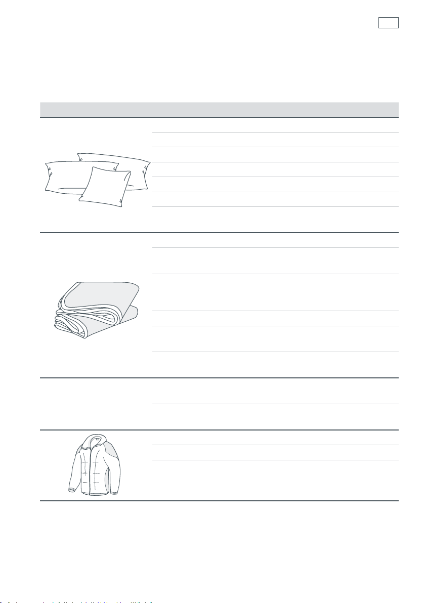
Drying special items
There are some articles that need to be dried in a special way. Before you dry any item that is
not described in AeroCare’s cycles (refer to pages 56 to 60), refer to the table below. Always
remember to follow the manufacturer’s instructions (please read the care label of the item).
Item Special instructions
Pillows
Blankets/throws
Plastic, foam rubber, and
rubber-backed products
Jackets
Check the care label – can the pillow be dried in the dryer?
Do not dry foam rubber pillows.
Check for weak seams where feathers or fillings could escape.
Dry only one average-sized pillow at a time.
Select the BULKY cycle.
Check the pillow at regular intervals.
Note: It is important to ensure the pillow is completely dry to
prevent mildew from forming.
Check the care label – can the blanket be dried in the dryer?
Include 4 – 5 medium sized towels along with the blanket for
cushioning. This will help stop shrinkage from over-tumbling.
If you are drying more than one blanket, ensure the blankets do
not fill more than half of the dryer, otherwise there will not be
enough space for them to tumble.
Select the BULKY cycle.
On completion, remove the blanket, shake and, if needed,
stretch the blanket back to its original shape.
Note: It is important to ensure the blanket is completely dry to
prevent mildew from forming.
Do not dry products containing foam rubber, plastic or rubber
on any cycle other than AIR DRY.
Drying these types of garments on any cycle other than AIR DRY
is a fire hazard.
Check the care label – can the jacket be dried in the dryer?
Check that all zippers and/or buttons are fastened.
Select the BULKY cycle.
61
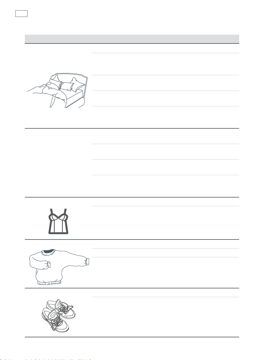
62
Drying special items
Item Special instructions
Extra large items
(including bedspreads
and comforters)
“In Dryer” dry-cleaning
products
Delicates, fine fabrics
Check the care label – can the item be safely dried in the dryer?
We recommend using the BULKY cycle. Note: we recommend
drying synthetic-type comforters and bedspreads using the AIR
DRY cycle ONLY.
It is best to check the item halfway though the cycle to ensure
even drying.
If the item contains feathers or down, add a heavy item (eg a
damp wet towel tied in a knot) to the load to help ‘fluff ’ the item.
Ensure the load does not sit higher than level with the top edge
of the door handle (close the door to assess this) before starting
the cycle.
Ensure the dry-cleaning product is recommended for use in a
domestic dryer.
Follow the manufacturer’s instructions for how to prepare
theload.
Set the dryer to the EASY IRON cycle, this cycle uses a
mediumheat.
At the end of the cycle remove the dry-cleaning product from
the machine and continue to follow the dry-cleaning product’s
instructions.
Check the care label – can the item be dried in the dryer?
Use a low heat setting (or no heat). We recommend the
DELICATE, or RACK DRY cycle (for items too delicate to tumble).
Woolens, silks Check the care label – can the item be dried in the dryer?
Use the drying rack – place item(s) flat on the rack.
Use the RACK DRY cycle.
Soft toys, shoes
Use the drying rack – sit item on the rack.
Use the RACK DRY cycle.

Drying cycle options
63
Once you have selected your drying cycle you may wish to change the default drying options.
Dryness Level
Your AeroCare dryer takes the guess work out of choosing drying times by sensing the dryness
of the load. When your dryer senses that the clothes have dried to the dryness level you have
selected, the dryer will automatically turn off.
AeroCare offers up to four dryness levels to choose from, depending on what dryer model you
have. This allows you to customize how dry you would like your load to be at the end of the cycle.
Choose the dryness level to suit your load depending on how dry you wish your clothes to be.
If you find the load is not dry enough, select the next dryness level up. The higher the level, the
longer the drying time and the drier your clothes will become.
Damp
Suitable for delicate
light-weight fabrics
and garments you
may wish to iron dry
Damp Dry
(selected models only)
An ideal setting for
lightweight cotton
items that you want
less dry
Dry Extra Dry
Designed to provide
items dry enough to
be worn immediately
Useful for drying
items that you wish to
store (cupboard dry)
If items are still damp, or too dry at the conclusion of the cycle, next time try a different dryness
level setting to customize the dryness level to your personal preference.
Cooling
When the dryer has sensed that the load is dry it will
automatically go into a cool-down phase. During COOLING
the drum tumbles and cool air is blown through the clothes.
This reduces wrinkling if the clothes are left in the dryer after
the cycle has completed.
Fig.48 Cooling
Drying Temp
There are up to four drying temperatures you can choose from: High, Medium,
Low, Extra Low (available on selected models only).
Each drying cycle is set to a default temperature to ensure the best possible
fabric care for your clothes.
To select a different drying temperature, touch the DRYING TEMP button until
the light next to your desired drying temperature is illuminated.
Note: not all temperatures are available on all cycles, for clothes care reasons.
Fig.49 Drying
temperature options

64
Drying cycle options
Wrinkle Free
Select the WRINKLE FREE if you wish to minimize wrinkling. At the end of
the cycle, the drum will rotate for 30 seconds every 5 minutes circulating
cool air through the load to minimize wrinkling and creasing. This is
particularly useful if you cannot remove the items immediately after the
cycle ends.
WRINKLE FREE can be selected on any cycle (except ENERGY SAVER,
RACK DRY and AIR DRY) and can be turned ON or OFF at any time
during the cycle by touching START/PAUSE, then WRINKLE FREE to OFF.
WRINKLE FREE will operate for a maximum of 24 hours if not stopped
beforehand. To stop WRINKLE FREE at any time touch START/PAUSE, or
open the door. You can then remove your items. Touch POWER to stop
the cycle and turn the dryer off.
After completing each tumble AeroCare will beep to remind you that the load is dry and can
beremoved.
Note: WRINKLE FREE is automatically selected on the EASY IRON cycle.
Fig.50 WRINKLE FREE
option ON
Delay Start (selected models only)
The DELAY START option enables you to delay the start of the drying cycle from between five
minutes and 18 hours. Time delays you can select are 5 mins, 15 mins, 30 mins, 1 hour, and then
hourly up to 10 hours, then for either 12 hours, 15 hours or 18 hours. This can be useful to time
your drying to finish when you arrive home from work, or to start when power rates are lower.
To program a DELAY START, simply touch the DELAY START option button to select ON, then the
MORE
START/PAUSE to confirm your selection and start the countdown. Once started, the time will
countdown on the digital display panel in one minute increments (or one hour increments
when the DELAY START time selected is greater than 10 hours). The START/PAUSE light will stop
flashing and turn on solid. The dryer will tumble periodically during the delay start countdown.
Touch the DELAY START button to turn DELAY START off.
To cancel a delay start time once it is counting down, simply touch START/PAUSE, then touch the
DELAY START button to select OFF to disable the feature. Touch START/PAUSE to start the cycle
immediately.
Note: we strongly recommend that you avoid using DELAY START for damp, non-colorfast items
as this may cause dye to transfer from one item to another.
button to increase the delay time and LESS button to decrease the time. Touch

Drying cycle options
Damp/Dry Signal (selected models only)
When your load reaches the DAMP/DRY stage, the dryer will play a musical series of beeps to
alert you to remove any items you wish to, and then continue drying until your load reaches
the dryness level you selected. This reminds you to remove some items in your load before they
become dry, so is ideal for items that tend to crease easily and require ironing, or may shrink
when tumble dried.
Drum Reverse (selected models only)
When DRUM REVERSE is turned ON, AeroCare will automatically change the direction of the
drum regularly to ensure more even drying, and reducing roping and tangling of items.
65

66
Dryer operation
Starting a drying cycle
Once you have chosen all your desired settings, ensure the door is closed and touch START/PAUSE
(located on the right-hand side of the control panel).
Stopping your dryer
Your AeroCare dryer can be stopped during any stage of the drying process, to allow you to
check on your load or add/remove clothes. To do this, simply open the dryer door or touch
START/PAUSE and open the door. There will be a slight delay as the drum slows down and stops.
To restart your dryer, close the door and touch START/PAUSE.
Important!
If you wish to stop the dryer before the cycle is finished, you MUST remove the clothes
IMMEDIATELY and spread them out to cool. DO NOT leave the clothes in the dryer or bunched up
in a clothes basket. There is a risk of spontaneous combustion.
If the cycle is interrupted before it progresses into COOLING, the clothes and parts of the drum
may be extremely hot. Take extreme care when removing the clothes load.
Finishing your cycle early
AeroCare will advance through the progress lights as it dries and will switch off once it has
completed the COOLING (final) phase of the cycle.
The COOLING phase means the heating elements switch off and the clothes are tumbled without
heat. When AeroCare senses the clothes are cool, the dryer will automatically end the cycle (this
takes between two and 10 minutes depending on the size of your load).
If you wish to finish your drying cycle early you can pause the current cycle and select the
AIRDRY cycle (select a cycle time of at least 10 minutes to cool the load down before removing it
from the dryer).
Beeps
At the end of the cycle, the dryer will beep to alert you that the load has completed drying.
You can modify the number of beeps that sound, or for the dryer to not beep at all. The dryer
defaults to five beeps. Please refer to page 72 for details on modifying the number of end of
cycle beeps.

Dryer operation
Drying times
Operation of the dryer and drying times of clothes loads can be affected by a number of factors
including (but not limited to):
The drying cycle chosen
Load size
Size of the items
Type of fabric
Load wetness
Location of the dryer
Ambient/environmental conditions
Venting method
Heat used (electric, natural gas or LP gas)
Condition of exhaust ducts
Fabric softener sheets
If you want to use fabric softener sheets, you must ensure that they are labeled “dryer safe”.
Always follow the manufacturer’s instructions on the packaging. Do not place them in a dryer
with warm clothes as there is a chance the fabric softener in the sheet may stain your clothes.
Only use a softener sheet once, then discard it.
67

68
Care labels
Below is a selection of care label symbols that garment manufacturer’s use to show how their
garments should be dried. We’ve converted these symbols into the cycles and heat settings
that we recommend you use in the AeroCare dryer. By following our recommendations, you can
ensure that your clothes will retain their appearance over time.
Tumble
dry symbols
Drying cycle we
recommend
Tumble
dry symbols
Drying cycle we
recommend
Additional drying
instructions
Normal Permanent
Press
REGULAR,
HEAVY,
ENERGY SAVER
Any heat High Medium Low No heat
Any cycle
Hang to dry
(line dry)
EASY IRON DELICATE
REGULAR,
HEAVY,
ALLERGY
EASY IRON,
BULKY
Drip dry Dry in shade Dry flat
Delicate Do not
tumble dry
Do not place
in dryer
DELICATE
AIR DRY,
RACK DRY
Do not place articles with these symbols in the dryer.

Drying rack
The drying rack helps to dry items such as sports shoes,
sweaters, hats and stuffed toys – all those delicate items that are
best dried without tumbling.
Always use the drying rack when using the RACK DRY cycle. Also
use a low temperature (a maximum of MED drying temp can be
selected only).
To install the drying rack, guide the rack (with the end of the
rack with the hooks extending closest to you) into the dryer.
Hold the back of the rack up towards the top of the drum and
hook the rack into the lint filter housing (with the lint filter
in place). Lower the rack so the longer ‘legs’ slide down and
sit against the front inner of the drum. Ensure the rack sits
horizontally in place.
Do not use the AUTOMATIC CYCLES (ie REGULAR, HEAVY, DELICATE, ENERGY SAVER, EASY IRON,
BULKY, ALLERGY ) when using the drying rack, as the dryer is unable to sense articles placed on
the drying rack and therefore cannot determine when articles are dry. Use the RACK DRY cycle
when placing items on the drying rack, ensure they do not hang over the edge of the drying
rack, as this may result in damage.
Drying rack part number: WC212D1411G002
Fig.51 Drying rack
69
Important!
Check articles regularly throughout the cycle to avoid over-drying.
Do not put other items in the dryer while you are drying items on the drying rack.
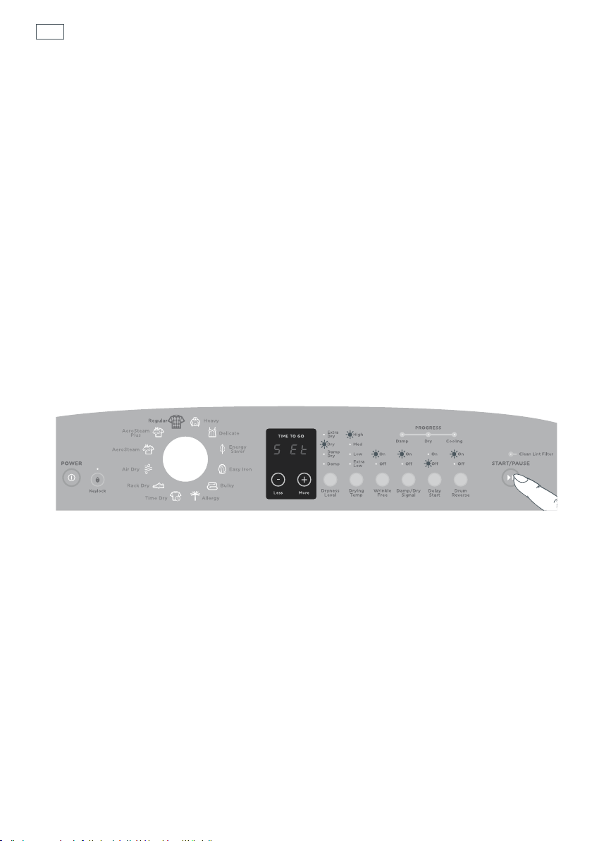
70
Customizing drying cycles
To customize a cycle
You can program your AeroCare dryer to remember the drying options you prefer for each
drying cycle. For instance, you may want to set the REGULAR cycle to operate the WRINKLE FREE
option every cycle, or set the TIME DRY cycle to a lower DRYING TEMP.
1
Touch POWER.
2
Turn the dial to select the cycle you wish to customize.
3
Touch and hold the button of the preferred option you want to customize, eg DRYING TEMP,
for three seconds. You will hear two quick beeps and the cycle icon will flash. The screen will
display “SEt”.
4
Select your preferred setting for this option, and any other options you wish to customize for
the cycle (ie you can customize other options at this point also).
Note: some options may not be selectable for clothes care reasons. The dryer will beep to alert
you when settings cannot be selected for that cycle.
5
Touch the START/PAUSE button to store your customized cycle. A long beep will sound to
confirm that your changes have been saved.
To modify your customized drying cycle again, simply repeat these steps. To return all drying
cycles to their factory default settings, please refer to page 72.
Fig.52 Customizing a drying cycle, eg customizing the WRINKLE FREE option to operate for every REGULAR cycle
Note: the control panel may differ depending on what model of dryer you have

Changing pre-set options
Changing pre-set options
Option Adjustment mode
In this mode you can modify the number of beeps that sound at the end of the cycle (ie end of
cycle (EOC) beeps), and reset the dryer to the settings it left the factory with (factory reset).
Note: DRYNESS LEVEL and DRYING TEMP settings cannot be modified.
To enter Option Adjustment mode
1
Turn the machine on at the wall but do not touch the POWER button. Touch and hold the
KEYLOCK and START/PAUSE buttons for three seconds. You will hear three quick beeps
indicating you have entered Option Adjustment mode. The diagram below shows how the drying
cycle icons relate to the options you can change. Page 72 explains the options in more detail.
2
Use the dial and buttons on the control panel to make your changes to the pre-set options.
3
Touch POWER to return to normal mode when you have finished modifying your options. Your
dryer will automatically remember your changes.
Adjusting your options
1
Enter the Option Adjustment mode (refer above).
2
The diagram below shows how the drying cycle icons relate to the options you can change.
The two options (the number of end of cycle beeps, and resetting the factory defaults) you can
adjust are accessible using the HEAVY and DELICATE cycles.
3
Use the MORE and LESS buttons underneath the digital display to scroll through the
available settings of your selected option.
71
Fig.53 Option Adjustment mode
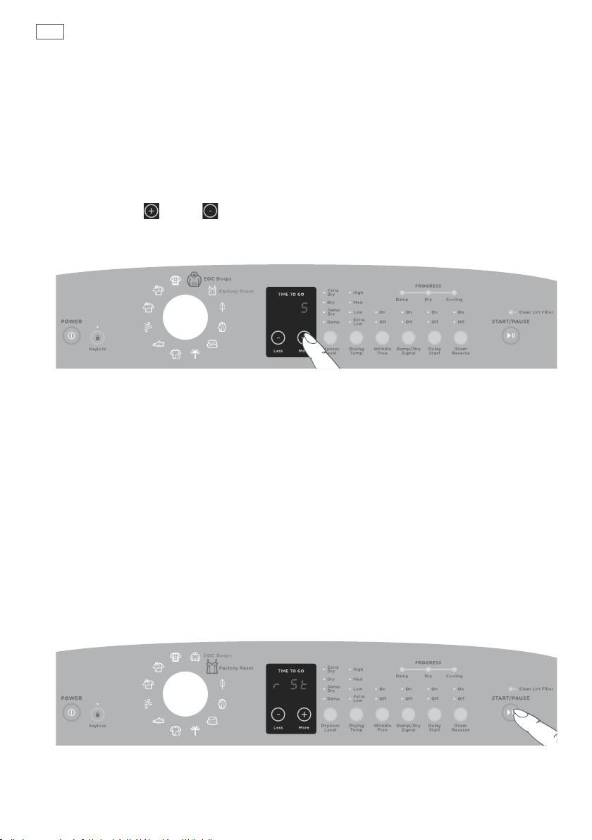
72
Changing pre-set options
End of cycle beeps
The beeps signalling the end of the cycle can be set to O (no beeps), 5 beeps or 15 beeps. The
default setting is 5 beeps.
To modify the number of beeps sounding at the end of the cycle:
1
Enter Option Adjustment mode (refer to page 71).
2
Select the HEAVY cycle.
3
Touch the MORE or LESS buttons to increase the number of beeps, or for no beeps to
sound at the end of the cycle.
4
Touch POWER to save your settings.
Fig.54 Adjusting the end of cycle beeps
Factory reset
You can reset your dryer to the default settings it left the factory with.
To reset your dryer to its factory settings:
1
Enter Option Adjustment mode (refer to page 71).
2
Select the DELICATE cycle.
3
The display will show “rSt”. Touch the START/PAUSE button for three seconds to reset your dryer
to its factory settings.
Note: this action will reset the dryer to the default settings, exit Option Adjustment mode and
power off your washer.
Touch POWER to exit if you do not wish to reset your dryer.
Fig.55 Resetting back to the factory settings
Remember, to save changes and exit from the Option Adjustment mode at any time (ie return to
normal operating mode), touch the POWER button.

Caring for your dryer
Clean your dryer with a soft damp cloth and wipe dry. Do not use
scouring cleaners as they can damage the paint and plastic surfaces.
Before you start cleaning your AeroCare dryer, ensure that it is
disconnected from the power (ie remove the plug from the power
outlet), or that KEYLOCK has been activated (refer to page 53).
Interior
The drum is rust-resistant. However, colored fabrics which lose
color or bleed during washing may cause discoloration of the
dryer drum. We recommend that the dryer drum be cleaned with
a cloth using a paste made from detergent and water, or a nonabrasive cleaner. Complete the cleaning by thoroughly wiping the
drum with a moist cloth, and then drying several wet rags or old
towels for 20 to 30 minutes using the TIME DRY cycle before using
the dryer normally.
Exterior
Wipe off any spills or washing compounds/products. Wipe or dust with a damp cloth. Do not strike
the surface with sharp objects. Pre-treatment products may damage parts of your dryer. Please
treat soiled or stained items where the pre-treatment will not come in contact with dryer surfaces.
Cleaning the control panel and machine top
Use a soft damp cloth to wipe all surfaces, and wipe dry. Avoid using chemical or scouring
cleaners, as these will damage the paint and plastic surfaces of your dryer.
73
Important!
The SmartTouch™ Control Dial is not designed to be removable for cleaning. Do not attempt to
remove the dial.
Pre-treatment sprays
Do not use pre-treatment sprays or liquids on or near your dryer as they can damage your
machine’s control panel as well as any of its plastic parts. Damage to your dryer caused by pretreatment products will not be covered by the limited warranty.
Stains
If stains appear inside the drum of your machine, mix a detergent with water to create a paste (or
use a non-flammable liquid cleaner) and wipe over the stain with a soft cloth. Then dry several
wet rags or old towels for 20 to 30 minutes using the TIME DRY cycle to remove all traces of the
cleaner.

74
Caring for your dryer
Lint filter
Lint is generally formed during wearing and washing. Lint and
fibers released from clothes during the drying cycle are collected
in the lint filter.
It is important to clean the lint filter after every load, as the lint
produced in the drying process can become a fire hazard if it
is allowed to accumulate in or around your dryer. AeroCare will
flash the “Clean Lint Filter” signal light on the panel each time
you power your dryer on to remind you to clean the lint filter.
Remove the lint filter from the housing and wipe the surface with your fingers. It is easier to
remove the lint when your fingers are moistened. A clean lint filter will ensure your clothes
remain lint-free and your dryer will operate at maximum efficiency.
Be sure to replace the lint filter before using the dryer.
Fig.56 Cleaning the lint filter
Important!
If the lint filter becomes damaged, contact Fisher & Paykel (refer to page 84) to arrange getting a
new filter. Do not operate your dryer with a damaged lint filter or without the lint filter in place,
as this will cause damage to your dryer.
Exhaust duct
The dryer exhaust ducting must be inspected and cleaned
periodically by an Authorized Service Agent to remove
accumulated lint and prevent clogging. This will help keep your
dryer operating at optimum performance. A partially clogged
exhaust can lengthen the drying time.
To clean the exhaust duct follow these steps:
1
Turn off the electrical supply by disconnecting the plug from the
power socket.
2
Disconnect the exhaust duct from the dryer.
3
Vacuum the exhaust duct with the hose attachment or attach a
rag to a pole or drain cleaning wire and clean the duct.
Fig.57 Cleaning the exhaust duct
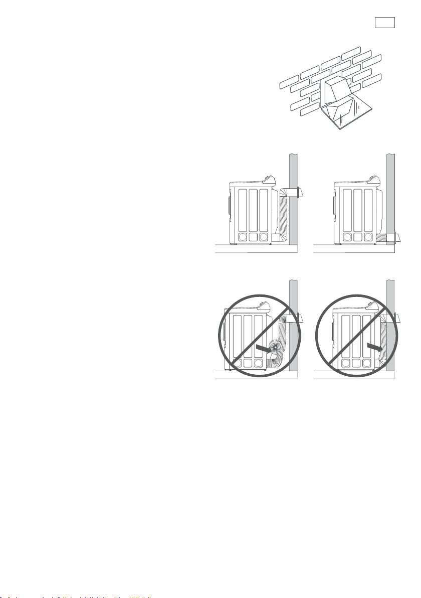
Caring for your dryer
Exhaust hood
Ensure the inside flaps or any damper on the exhaust hood
moves sufficiently and opens and shuts freely (you may want
to check with a mirror).
Make sure inside flaps are fully open when dryer is operating.
Make sure there is not wildlife (birds, insects, etc) nesting
inside the exhaust duct or hood.
Venting
For best drying performance, the dryer needs
to be properly vented.
Ensure:
Only rigid metal or flexible metal 4” (102 mm)
diameter ductwork has been used inside the
dryer cabinet or for exhausting to the outside.
The shortest length possible has been used.
The exhaust duct is not crushed or collapsed.
The duct is not resting on sharp objects.
Plastic or other combustible ductwork has
NOT BEEN USED.
75
Fig.58 Checking the exhaust hood
Correct venting
Carefully follow the details on exhausting
the dryer in the “Installation instructions”.
Refer to page 26.
Ensure that the area around the dryer is kept
clear and free from combustible materials,
gasoline and other flammable vapors or
liquids. Ensure also that the dyer area is kept
clear and free from items that would obstruct
the flow of combustion and ventilation air.
Important!
Venting must conform to local building codes.
Incorrect venting
Fig.59 Correct and incorrect venting

76
Before you call for service
User warnings
Your dryer is capable of diagnosing a number of its own problems. A continuous series of beeps
will sound and a code will be displayed when it has a problem that you can correct yourself. All
control panel lights will turn off and a code will be displayed to inform you what the problem is.
To stop the beep sounding, press any button on the control panel. Do not try to continue your
drying cycle once you stop the noise. You must address the problem the dryer is alerting you to.
Check this chart before you call for service.
Description Displayed as What should you do?
The door is
not closed
Once you have addressed the issue the user warning was alerting you to, try using your dryer
normally.
If the symptom persists, call your Fisher & Paykel Authorized Service Agent (refer to page 84).
Close the door fully and touch START/PAUSE.
Try opening and closing the door again.
Reposition the load, make sure the load is correctly in the
drum and that no items are caught in the way of the door.
Fault codes
When a continuous series of beeps is sounded, all the lights turn off on the control panel and a
number appears on the display; a fault has occurred. The dryer will automatically enter this mode
if a fault occurs. The fault code will be displayed as a number on the digital display. To stop the
sound, touch any button and perform the following steps:
1
Unplug your dryer from the power outlet.
2
Wait one minute and plug the dryer back in.
3
Check the dryer is correctly level (refer to page 44).
4
Remove your dryer load and retry.
5
Perform a TIME DRY cycle (20 mins).
6
If the fault re-occurs repeat steps 1 and 2.
7
If the machine still will not work you will be required to call a Fisher & Paykel Authorized Service
Agent to arrange service (refer to page 84). Record the fault code number displayed and the
serial number of your dryer (located on the drum opening surround (open the door)) before
calling. The fault code will indicate to the Service Agent what the problem could potentially be.
If a fault code is being displayed, you can still turn your dryer off by pressing POWER.
Solving operating problems
The following is a list of problems you may encounter when using this appliance and some
suggestions that may help to correct the problem. If you still have problems, please contact a
Fisher & Paykel Authorized Service Agent.
Pressing POWER does not turn on the dryer
Is the electrical cord plugged in? If not, plug the cord in.
If there is a switch at the power point, is it switched on?
Could your household power supply be at fault? If your plug is suitable, try plugging another
electrical appliance into the same outlet.
Turn off the power at the power point. Unplug the dryer from the wall. Wait 60 seconds, plug it
back in, turn it on and try again.
Check your house circuit breakers and fuses. If they are at fault contact an electrician.
Is the power cord damaged?
Dryer does not heat
Is the dryer set to the AIR DRY cycle?
Is the gas turned on (gas dryers only)?
Has the dryer progressed to COOLING? Check the progress lights.
If the problem persists call for service.
Pressing START / PAUSE does not start the drying cycle
Did you touch START/PAUSE firmly enough?
Is the dryer paused? If so, the START/PAUSE light will be flashing.
Is the dryer door closed properly?
Is there a user warning or fault code displayed on the control panel? Refer to page 76.
Is the dryer making a beeping noise? Refer to page 79.
Has the lint filter been emptied?
Is the lint filter in place?
Has the dryer been overloaded?
Is DELAY START set?
Dryer keeps stopping and starting
Your dryer has a reverse action tumble. When it changes direction it will pause momentarily,
and will then start again in the opposite direction. This is normal.
Has WRINKLE FREE been turned on? WRINKLE FREE ON is the default setting for the EASYIRON
cycle, meaning the drum will rotate periodically after the cycle has finished to minimize
wrinkling.
77

78
Solving operating problems
Dryer stops working mid cycle
Is there a fault code or user warning displayed on the digital display panel? Is the machine beeping?
Was there a power failure? If so, when power resumes, you will need to reselect your chosen
drying cycle and touch START/PAUSE to resume the cycle.
Has the dryer been paused?
Is the door open?
Drying is taking too long
Have you selected an appropriate cycle for the load?
What dryness level did you select?
Try selecting a lower/higher temperature.
Is the dryer overloaded for the cycle?
Try dividing the load in half and dry half at a time.
Is the lint filter blocked? Check this does not need to be cleaned.
If you have a gas dryer, is the gas turned on? Could your gas supply be at fault?
What environmental conditions are you using the dryer in? Hot, humid conditions may cause the
dryer to become less efficient and take longer to dry a load. High altitude will also affect your
dryers performance, including making your drying cycle longer.
How wet was the load when you put it in? It might require water being hand-wrung or machinespun out of the load before drying.
Is the airflow system free from obstruction?
Has the dryer been exhausted correctly? Is the exhaust duct distance too great?
Were items getting wrapped up inside other items? Separate items and dry items of similar
‘weight’ together.
Open items out when you place them in the dryer. Do not fold them up. Untangle items, eg pull
long sleeves out so they are not stuck on the inside of the garment.
Items got too hot or damaged
Did you select the appropriate cycle and options for the items?
Did you remove the items before the end of cycle cool down? This may damage clothing if items
are not spread out and exposed to air to cool once removed from the dryer.

Solving operating problems
Dryer is beeping, displaying unfamiliar light patterns and/or a message on the digital display
See the USER WARNINGS and FAULT CODES sections (refer to page 76).
Try turning the dryer off, waiting 30 seconds and turning it back on.
Cycle time longer than usual / Inaccurate time remaining/ Adjustment of time remaining
during the cycle
Cycle time is approximate and may be affected by the composition and size of the load, how dry
the load was to begin with, environmental conditions, cycle and options selected, sensing while
drying and any interruptions during the cycle (refer to page 52).
Noises
Have you overloaded the machine?
Your dryer has a reverse action tumble. When it changes direction it will pause momentarily and
will start again in the opposite direction. This is normal.
Continuous beeping or a musical series of beeps with a message displayed on digital display (refer
to page 76).
End of cycle beeps – These can be turned off (refer to page 72).
Cannot see steam at start of cycle, or an any time during the cycle
The release of steam occurs at different times in the cycle and may not be visible.
Check whether the steam nozzle might be blocked from impurities in the water supply. You may
be required call an Authorized Service Agent to replace this.
Water visible on inside of door and lint filter after steam cycle
Steam produced during the cycle may condense in these locations and is normal.
Water drips from inside of door after steam cycle
Steam produced during the cycle may condense on the inside of the door. This is normal operation
of the dryer.
Puddle of water on the floor in front of the dryer after using a steam cycle
Have you used a large enough load for the steam cycle you have selected? Refer to page 60.
Try adding more items to the dryer.
Puddle of water on the floor at the rear of the dryer
Check the inlet hose connection. Tighten if necessary.
Check that the rubber washer is installed in the inlet hose.
79

80
Solving drying problems
Linting
Has the lint filter been cleaned and replaced correctly?
Was the dryer overloaded?
Have you separated lint-shedding garments (eg towels) from lint receiving garments (eg synthetics).
Have you checked your pockets for tissues or other items that could have been left in them?
Dry similar colors together (eg light items with light items, dark items with dark items).
Have you over-dried your load? Over-drying can cause lint-attracting static electricity. Try a lower
dryness setting or use an AUTOSENSING cycle instead of TIME DRY.
Were new items (eg towels, flannelette sheets) dried in your dryer recently?
Static problems
Have your clothes been over-dried? Select a lower dryness setting.
Have you used fabric softener? Place fabric softener sheets in the dryer.
Fabric damage
Has the load been over-dried? Select a lower dryness setting.
Is tumble drying recommended for the item? Check the care labels inside garments.
Did you follow the instructions on the care label of clothing for tumble drying correctly?
Were delicate items dried separately on the DELICATE cycle or the RACK DRY cycle?
Were there metal parts on the items? Were zips and other clasps done up?
Were items separated and dried on an appropriate cycle for the fabric type?
If using the RACK DRY cycle, did items fall off the rack?
Was an appropriate drying temperature and dryness level selected for the fabric type?
Did you monitor the dryness of clothes if dried on a TIME DRY cycle?
Did you remove the items before the end of cycle cool down? This may damage clothing if it is not
spread out and exposed to air to cool once removed from the dryer.
Dye transfer
Remember to separate whites and colors.
Do not leave wet items sitting in the dryer for long periods before drying, if they are prone to color
run. If you do intend to leave them for long periods before drying, then separate the load and put
color run items aside.

Solving drying problems
Tangling
Try separating out larger items from smaller items.
Load items individually and loosely into the dryer and do not fold the items.
Try using the EASY IRON cycle to dry shirts.
Try drying smaller load sizes.
Dry pantyhose, bras and any other delicate items prone to tangling in a delicates bag or on the
RACK DRY cycle. Note: items may not dry as well in a delicates bag.
Dry sheets and comforter covers separately from other laundry.
Ensure comforter covers are buttoned or domed closed before drying
Clothes are wrinkled
Was the washer or dryer overloaded? Decrease the load size.
Selecting the EASY IRON cycle will minimize creasing.
Did you remove your clothes as soon as the dryer was finished? Use the WRINKLE FREE option, if
you cannot return to the dryer in time.
Have your clothes been over-dried? Select a lower dryness level. Check your garments care labels.
Try not to leave wet clothes sitting in the dryer for a long period before starting it.
Damp patches on items after using a steam cycle
Steam may condense inside the drum which your items may come in contact with. Add more
items to the dryer if this occurs.
Items wrinkled even after using one of the steam cycles
Are there too many items in the load? Reduce the number of items.
Items in the dryer are wet after using one of the steam cycles
Are there enough items in the load? Add more items.
Check the lint filter is clean.
Use the AEROSTEAM cycle if you are drying childrens’ and infants clothing.
81

82
Limited warranty
When you purchase any new Fisher & Paykel AeroCare dryer product for personal or
consumer use you automatically receive a two year limited warranty covering parts and
labor for servicing within the 48 mainland United States, Hawaii, Alaska, Washington DC and
Canada. Products for use in Canada must be purchased through the Canadian distribution
channel to ensure regulatory compliance.
Fisher & Paykel undertakes to:
Repair or at its option replace without cost to the owner either for material or labor any part
of the product, the serial number of which appears on the product, which is found to be
defective. In Alaska, you must pay to ship the product to the service shop or for the service
technician’s travel to your home. If the product is installed in a motor vehicle, boat or similar
mobile facility, you must bring it to the service shop at your expense or pay for the service
technician’s travel to the location of the product. If we are unable to repair a defective part
of the product after a reasonable number of attempts, at our option we may replace the part
or the product, or we may provide you a full refund of the purchase price of the product (not
including installation or other charges).
This limited warranty extends to the original purchaser and any succeeding owner of the
product for products purchased for ordinary single-family home use.
All service under this limited warranty shall be provided by Fisher & Paykel or its Authorized
Service Agent during normal business hours.
How long does this limited warranty last?
Our liability under this limited warranty expires two years from the date of purchase of
the product by the first consumer.
Our liability under any implied warranties, including the implied warranty of merchantability
(an unwritten warranty that the product is fit for ordinary use) also expires two years (or such
longer period as required by applicable law) from the date of purchase of the product by the
first consumer. Some States do not allow limitations on how long an implied warranty lasts,
so this limit on implied warranties may not apply to you.

Limited warranty
This limited warranty does not cover:
A
Service calls that are not related to any defect in the product. The cost of a service call will be
charged if the problem is not found to be a defect of the product. For example:
1. Correcting faulty installation of the product.
2. Instructing you how to use the product.
3. Replacing house fuses, resetting circuit breakers, correcting house wiring or plumbing, or
replacing light bulbs.
4. Correcting fault(s) caused by the user.
5. Changing the set-up of the product.
6. Unauthorized modifications of the product.
7. Noise or vibration that is considered normal, for example, drain/fan sounds or user
warning beeps.
8. Correcting damage caused by pests, for example, rats, cockroaches etc.
B
Defects caused by factors other than:
1. Normal domestic use or
2. Use in accordance with the product’s user guide.
C
Defects to the product caused by accident, neglect, misuse, fire, flood or Act of God.
D
The cost of repairs carried out by non-authorized repairers or the cost of correcting such
unauthorized repairs.
E
Travel fees and associated charges incurred when the product is installed in a location with
limited or restricted access (eg airplane flights, ferry charges, isolated geographic areas).
F
Normal recommended maintenance as set forth in the product’s User Guide.
83
If you have an installation problem contact your dealer or installer. You are responsible for
providing adequate electrical, exhausting and other connection facilities.
We are not responsible for consequential or incidental damages (the cost of repairing or
replacing other property damaged if the product is defective or any of your expenses caused if
the product is defective). Some States do not allow the exclusion or limitation of incidental or
consequential damages, so the above limitation or exclusion may not apply to you.

84
Limited warranty
How to get service
Please read your User Guide. If you then have any questions about operating the product,
need the name of your local Fisher & Paykel Authorized Service Agent, or believe the product is
defective and wish service under this limited warranty, please contact your dealer or call us at:
USA and Canada
TOLL FREE 1.888.9.FNP.USA (1.888.936.7872)
or use the link at: www.fisherpaykel.com/locator/servicer/
You may be required to provide reasonable proof of the date of purchase of the product before
the product will be serviced under this limited warranty.
Commercial use
If you are using the product in a commercial setting (any use other than a single family dwelling),
we agree to repair or replace, without cost to you for parts only, any defective parts, the serial
number of which appears on the product. Our liability for these repairs expires ONE YEAR from
the date of original purchase.
At our option we may replace the part or the product, or we may provide you a full refund of
the purchase price of the product (not including installation or other charges). All service under
this limited warranty shall be provided by Fisher & Paykel or its Authorized Service Agent during
normal business hours.
No other warranties
This limited warranty is the complete and exclusive agreement between you and Fisher & Paykel
regarding any defect in the product. None of our employees (or our Authorized Service Agents)
are authorized to make any addition or modification to this limited warranty.
Warrantor: Fisher & Paykel Appliances, Inc.
If you need further help concerning this limited warranty, please call us at above number, or
write to:
Fisher & Paykel Appliances, Inc.
5900 Skylab Road
Huntington Beach
CA 92647
This limited warranty gives you specific legal rights, and you may also have other rights which
vary from state to state.


www.sherpaykel.com
Copyright © Fisher & Paykel 2013. All rights reserved.
The product specifications in this booklet apply to the specific products
and models described at the date of issue. Under our policy of continuous
product improvement, these specifications may change at any time. You
should therefore check with your Dealer to ensure this booklet correctly
describes the product currently available.
US 10.2013F&P PN - 234D1668P001
 Loading...