

Page 1
Installation instructions
and User guide
AeroSmart clothes dryer
US CA (EN)
Page 2

WARNING: For your safety the
information in this manual must be
followed to minimize the risk of fire or
explosion or to prevent property
damage, personal injury or death.
—Do not store or use gasoline or other
flammable vapors and liquids in the
vicinity of this or any other appliance.
—WHAT TO DO IF YOU SMELL GAS
UК КМКМАЮКМК}МК>ЮК>««>Vi°
UК КМКМХVК>ЮКiiVМАV>КГЬМVЖК`К
not use any phone in your building.
UÊ i>ÀÊÌiÊÀ]ÊLÕ`}ÊÀÊ>Ài>ÊvÊ>Ê
occupants.
UÊ i`>ÌiÞÊV>ÊÞÕÀÊ}>ÃÊÃÕ««iÀÊvÀ
a neighbor’s phone. Follow the gas
supplier’s instructions.
UÊ vÊÞÕÊV>ÌÊ Ài>VÊÞÕÀÊ}>ÃÊÃÕ««iÀ]Ê
call the fire department.
—Installation and service must be
performed by a qualified installer, service
agency or the gas supplier.
The Governor of California is required to publish a list of substances known to the
state of California to cause cancer or reproductive harm and requires business to
warn customers of potential exposures to such substances.
WARNING!: Gas appliances contain or produce substances, which can cause death,
or serious illness and which are known to the State of California to cause cancer,
birth defects, or other reproductive harm. To reduce the risk from substances in
fuel or from fuel combustion, make sure this appliance is installed, operated, and
maintained according to the manufacturers instructions.
Page 3

Contents
Introduction 2
Important safety instructions 3
Installation instructions 7
The first time you turn your dryer on 32
Getting started quickly 34
Operating instructions 34
AeroSmart controls 36
Easy touch controls, The display screen 36
Using your dryer 37
Sorting and loading 37
Lint bucket 38
Choosing your drying cycle 39
Changing the drying cycle options 40
Drying cycle options 41
Drying cycle progress 42
Drying cycles explained 43
Lifestyle cycles 46
Special Care Handwash / Jeans / Freshen Up / Warm Up / Dryclean 47
Family Comforter / Pillows / Allergy / Shirts / Towels / Soft Toys 48
Sports Sportswear Light / Sportswear Heavy / Outdoor Wear /
Protection Equipment 50
Care labels 51
Lid Lock 52
Power failure 52
Settings Menu 53
Alarm Level / Screen Brightness / Key Lock Mode 53
Reminders / Hints / Language 54
Service Contacts / Trouble Shooting / Reset Defaults / Replay Intro 55
Caring for your AeroSmart dryer 56
Before you call for service 57
If your AeroSmart dryer beeps for help 57
Solving operating problems 58
Solving drying problems 59
Limited warranty 60
1
Important!
SAVE THESE INSTRUCTIONS
The models shown in this User Guide may not be available in all markets and are
subject to change at any time. For current details about model and specification
availability in your country, please visit our local website listed on the back cover
or contact your local Fisher & Paykel dealer.
Page 4
2
Introduction
Welcome to AeroSmart
Thank you for buying a Fisher & Paykel AeroSmart clothes dryer. We are very proud of this dryer
and trust it will serve you well for many years.
At Fisher & Paykel we aim to provide innovative products that are simple to use, ergonomic and
kind to the environment.
We have developed this dryer to treat your clothes with the utmost care, drying them gently,
so they will look better for longer. We trust you’ll enjoy the benefits of its easy loading drum,
reverse tumbling and unique lint removal system.
Please take the time to read this User Guide carefully. It will help you to operate and maintain
your new AeroSmart dryer.
Your safety, and the safety of others is very important. Located on your dryer and throughout this
guide are safety messages and instructions; it is important that you understand and follow them.
We hope you enjoy your new dryer, we have certainly enjoyed designing it for you.
Fig.1 AeroSmart dryer
Important!
It is important that this User Guide should be retained with your AeroSmart clothes dryer for
future reference. Should the appliance be sold or transferred to another owner, please ensure
that the User Guide is left with the appliance. This will ensure that the new owner can familiarise
themselves with the information and warnings contained within the Guide.
Page 5
Important safety instructions
Symbols
Symbols will be used in this Guide to highlight when extra care is required. Abide by these at all
times to ensure you and your family are not harmed while operating your dryer.
It is important to always act with caution and use common sense when operating your dryer.
Use only as instructed by the User Guide.
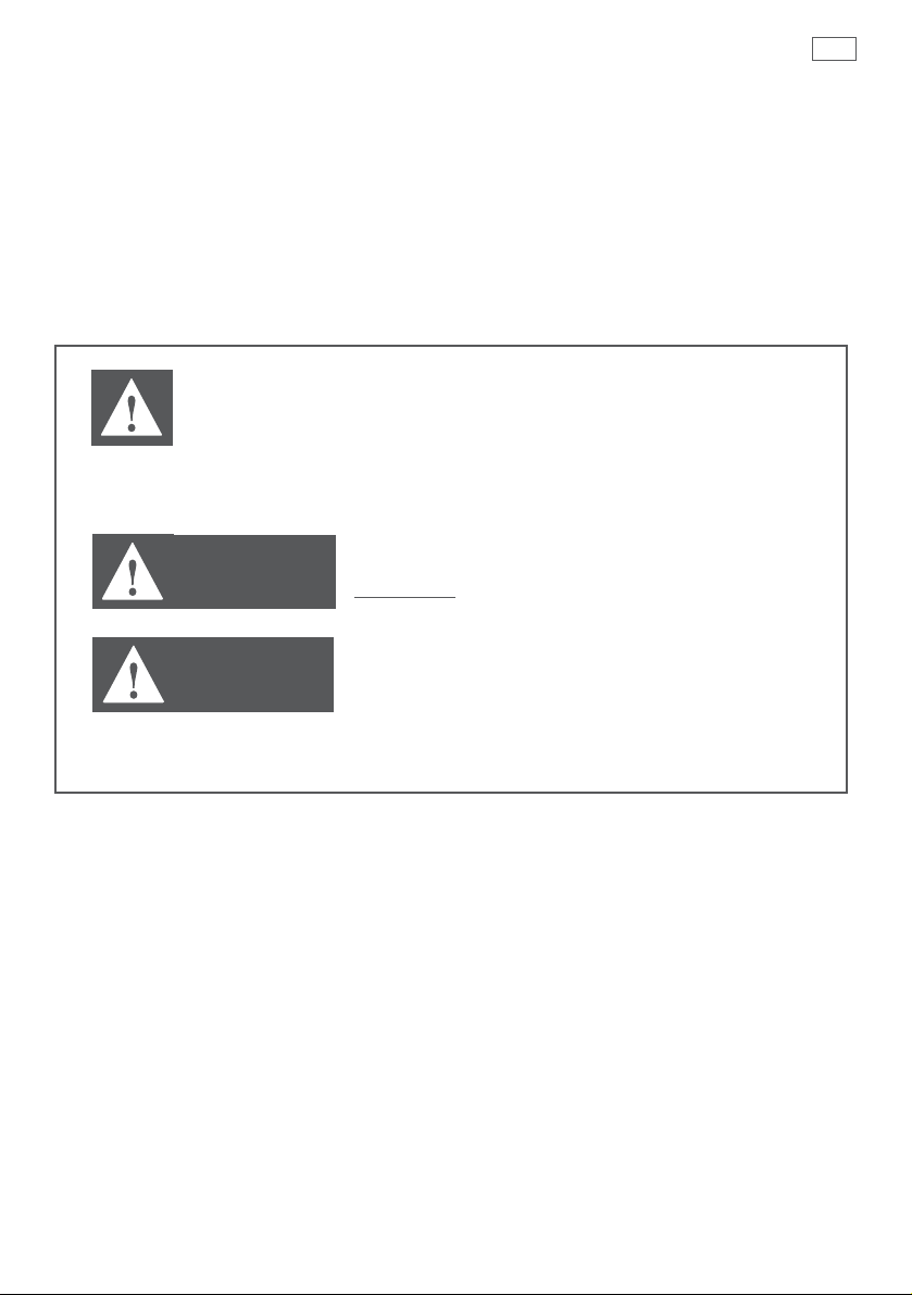
This is the safety alert symbol. This symbol alerts you to hazards that can kill
or hurt you and others.
The safety alert symbol and the word DANGER or WARNING will precede all
safety messages. These words mean:
3
DANGER
WARNING
All safety messages will identify the hazard, tell you how to reduce the chance of injury,
and tell you what can happen if the instructions are not followed.
You can be killed or seriously injured if you don’t
immediately follow instructions.
You can be killed or seriously injured if you don’t
follow instructions.
Page 6

4
Important safety instructions
WARNING!
Electric Shock Hazard
Follow the safety precautions outlined in this User Guide.
Failure to do so can result in death or electric shock.
Important safety precautions
Read all instructions carefully before using this dryer.
Use this dryer only for its intended purpose as described in this User Guide.
To minimize the possibility of electric shock, unplug this dryer from the power supply or disconnect
the dryer at the household distribution panel (by removing the fuse or switching
off the circuit breaker) before attempting any user maintenance or cleaning.
Installations must be performed by a qualified or licensed contractor, plumber or gasfitter qualified
or licensed by the state, province, or region where this appliance is being installed.
This dryer must be properly installed and located in accordance with the Installation Instructions
before it is used.
This dryer must be properly grounded to conform with all governing codes and ordinances. Follow
details in Installation Instructions.
Do not install or store the dryer where it will be exposed to water or exposed to the weather.
Connect to a properly protected, rated and sized power supply circuit to avoid electrical overload.
Do not repair or replace any part of the appliance or attempt any servicing, unless specifically
recommended in the published user repair instructions that you understand and have the skills to
carry out.
When disconnecting the dryer, pull by the plug rather than the cord or junction of the cord plug, to
avoid damage to the cord or junction of the cord plug.
Make sure the cord is located so that it will not be stepped on, tripped over or otherwise subject to
stress or damage.
Do not tamper with the controls or the lid lock.
Note: Pressing the POWER button does NOT disconnect the dryer from the power supply, even
though the lights are out.
Do not operate this dryer if it is damaged, malfunctioning, partially disassembled or has missing or
broken parts, including a damaged cord or plug.
This dryer must be directly connected to an approved fixed electrical outlet. It cannot be plugged into
an extension cord.
Page 7
Important safety instructions
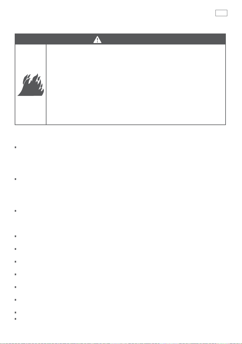
WARNING!
Fire Hazard
Only dry fabrics that have been washed with water.
Do not use heat to dry articles containing foam rubber or similarly textured
rubber-like materials. Dry on the Air Dry cycle.
A clothes dryer produces combustible lint and must be exhausted
outdoors. Take care to prevent the accumulation of lint around the exhaust
opening and in the surrounding area.
Do not use fabric softeners or products to eliminate static unless
recommended by the manufacturer of the fabric softener or product.
Failure to follow these instructions can result in death or personal injury.
To reduce the risk of fire in a tumble dryer the following should be observed:
Do not place items in a tumble dryer that have previously been cleaned in, washed in, soaked
in, or spot cleaned with flammable liquids or solids. They are a fire or explosion hazard.
Highly flammable substances commonly used in domestic environments include acetone,
denatured alcohol, gasoline, kerosene, some brands of spot removers and dry cleaning solvents,
turpentine, waxes, wax removers, vegetable oil, fish oil, massage oil, and cooking oil.
Do not leave hot oil-affected items in a pile or stack. This can prevent heat from escaping and
can create a fire hazard. Oil-affected items can ignite spontaneously, especially when exposed
to heat sources such as a tumble dryer. The items become warm causing an oxidation reaction
in the oil. This oxidation creates heat. If the heat cannot escape the items can become hot
enough to catch fire.
Do not use heat to dry items containing rubber, foam rubber, plastic or similar materials, (such
as padded bras, bath mats, rugs, bibs, baby pants, plastic bags, pillows etc), as these materials
might melt or burn. Some rubber materials when heated can under certain circumstances
produce fire by spontaneous combustion. Dry only on the AIR DRY cycle.
Unless specifically recommended by their manufacturer, do not use fabric softeners or similar
products in a tumble dryer.
Do not store or use gasoline or other flammable gases and liquids near this or any other
appliance.
Keep the area around and underneath your dryer free from the accumulation of combustible
materials such as lint, paper, rags, chemicals etc.
Do not store any items that may burn or melt (such as paper materials, plastics or plastic
containers etc) next to the dryer.
Empty the lint bucket before the lint reaches the top of the transparent section (usually once a
week).
The dryer must be exhausted to the outside. Carefully follow the venting details in the
Installation instructions.
Keep the floor around your dryer clean and dry to reduce the possibility of slipping.
If your dryer is running and you want to unload or add clothes, press START/PAUSE and wait
until the machine has unlocked the lid. Do not force it open.
5
Page 8

6
Important safety instructions
Do not reach into the appliance if the drum is moving.
Close supervision is necessary if this dryer is used by or near children. Do not allow children to
play inside, around or with this dryer or any other appliance.
Never climb on, climb into, or stand on the dryer top, lid or drum.
Undergarments that contain metal reinforcements should not be placed directly in the dryer.
Damage to the dryer can result if the metal reinforcements come loose during drying.
The interior of the appliance and exhaust duct should be cleaned periodically by qualified
service personnel.
Before the appliance is removed from service or discarded remove the lid and the drum door to
the drying compartment.
SAVE THESE INSTRUCTIONS
Page 9
Installation instructions
WARNING! – Risk of fire
Clothes dryer installation must be performed by a qualified installer.
Install the clothes dryer according to the manufacturer’s instructions and local codes.
Do not install a clothes dryer with flexible plastic venting materials. If flexible metal
(foil type) duct is installed, it must be of a specific type identified by the appliance
manufacturer as suitable for use with clothes dryers. Flexible venting materials are known
to collapse, be easily crushed, and trap lint. These conditions will obstruct clothes dryer
airflow and increase the risk of fire.
To reduce the risk of severe injury or death, follow all installation instructions.
SAVE THESE INSTRUCTIONS
Read the important safety instructions on pages 3 – 6 before you start installing the dryer.
Check to make sure you have all the tools and parts necessary to correctly install this appliance.
Tools required
¼’’ nut driver or socket wrench
Phillips screwdriver
Flat-blade screwdriver
Adjustable wrench 8” or 10” (200 mm or 250 mm) for gas connections
Pipe joint compound (pipe dope or tape) for gas pipe connections that is resistant to
LP Propane, Butane and Natural Gas (Gas models only)
Level
Caulking gun and compound (for installing new exhaust vent)
Gloves
Safety glasses
Knife
Duct tape
7
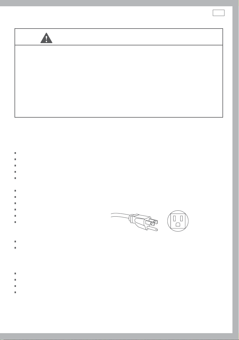
Parts supplied
2 feet inserts for front feet.
A power supply cord is supplied already connected to the gas dryer (Gas models only)
Check to make sure all parts have been supplied.
Fig.2 Power supply cord
Accessories
Mobile Home Installation Kit Part No 395488
Natural Gas to LP Conversion Kit Part No 395489 (Gas models only)
LP to Natural Gas Conversion Kit Part No 395490 (Gas models only)
Kit Element 208V Part No 395500 (Electric models only)
Parts needed
If you need to purchase a power supply cord kit or power supply cable, they must meet the
requirements outlined on page 21 (power supply). Check with local codes and read electrical, gas
and venting requirements before purchasing parts.
Page 10
8
Installation instructions
To the installer
The correct installation of the dryer is your responsibility.
Be sure you read the following instructions carefully before you start to install the dryer. These
instructions should be left with the home owner for future reference.
It is your responsibility to:
Observe all governing codes and ordinances.
Check code requirements. Some codes limit or do not permit installation of clothes dryers in
garages, closets, mobile homes or sleeping quarters. Contact your local building inspector.
Adhere to these installation instructions.
Allow for spacing requirements with side by side installations (refer page 9).
Make sure you have all items necessary for correct installation.
Properly install the dryer.
Contact a qualified installer to ensure that the electrical and gas installation meets all national
and local codes and ordinances. (See page 4).
Location requirements
WARNING!
Explosion Hazard
Keep flammable materials and vapors, such as gasoline, away from the dryer.
Place dryer at least 18 inches (460 mm) above the floor for a garage
installation.
Failure to do so can result in death, explosion, fire, or burns.
The dryer must be installed or stored in an area which is not exposed to water or weather.
It is extremely important that the dryer is installed in a well ventilated location. This dryer must
exhaust air outdoors. Do not install the dryer in any room or closet which does not permit the
free flow of replacement air.
The free area of any opening for the introduction of outside air shall not be less than twice the
area of the dryer exhaust outlet.
Before installing the dryer ensure that there is sufficient height to fully open the lid. Allow
sufficient room behind the dryer for the exhaust. The air intake is at the rear of the dryer. Ensure
that there is a sufficient air passage on each side of the dryer for intake air.
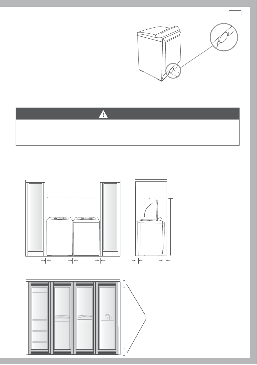
Page 11
Installation instructions
Location requirements
The area in which the dryer is located must be
kept clear and free from combustible materials,
gasoline and other flammable vapors and
liquids. A dryer produces combustible lint so
the area around the dryer must be cleaned
regularly to keep it free of lint.
Fig.3 Rear venting
This dryer can only be vented from the rear and must be exhausted to the outdoors.
Alcove or closet installation
WARNING!
When installing a dryer in a closet/alcove it must be exhausted to the outdoors. No other
fuel burning appliance can be installed in the same closet or alcove.
9
The top opening area in the door must be a minimum of 48 square inches (3100 mm2) and the
bottom opening area must have a minimum of 24 square inches (1550 mm
2
). These openings
must never be obstructed (a louvred door with the minimum air opening is acceptable).
Minimum installation clearances are required but more clearance is recommended.
min 56 /”
(1430 mm)
Fig.4 Minimum clearances
1” (25 mm) 1” (25 mm) 1” (25 mm)
min 2” (50 mm) min 3” (76 mm)
48 sq” (3100 mm2)
total ventation area
72 sq” (4650 mm
2
)
24 sq” (1550 mm
2
Fig.5 Minimum ventilation
)
Page 12
10
Installation instructions
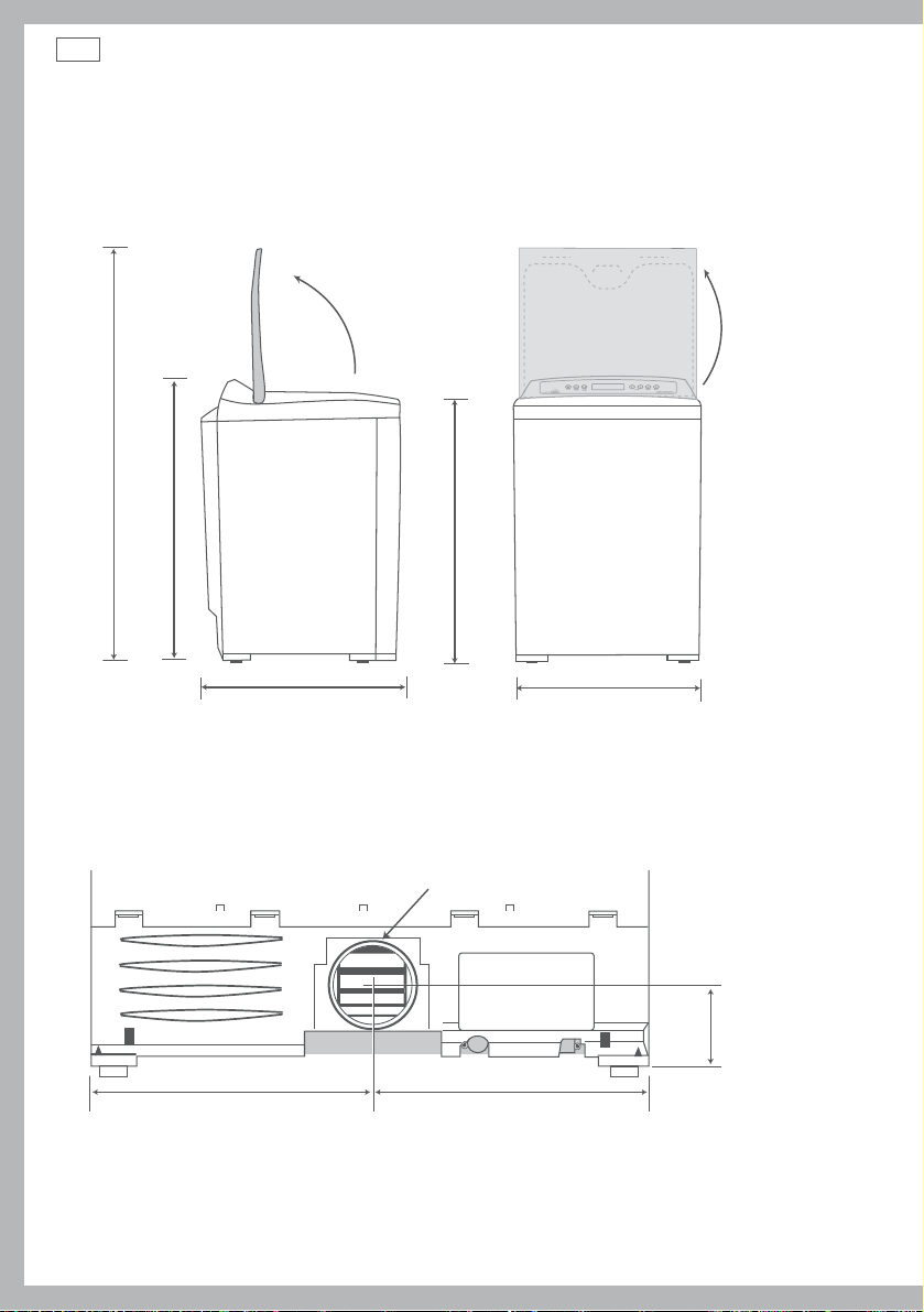
Dimensions
Check that there is enough clearance for the lid to fully open.
56” (1422 mm)
37” – 37 ⁄”
39 /” – 41 ⁄”
(1010 – 1050 mm)
(925 – 955 mm)
27 ⁄” (700 mm)
Exhaust outlet location
13 ⁄” (352 mm)
Fig.6 AeroSmart dimensions
Exhaust outlet
13 ⁄” (333 mm)
Fig.7 Exhaust outlet dimensions
27” (685 mm)
Does not include
4 ⁄”
foot height
(111 mm)
Page 13
Installation instructions
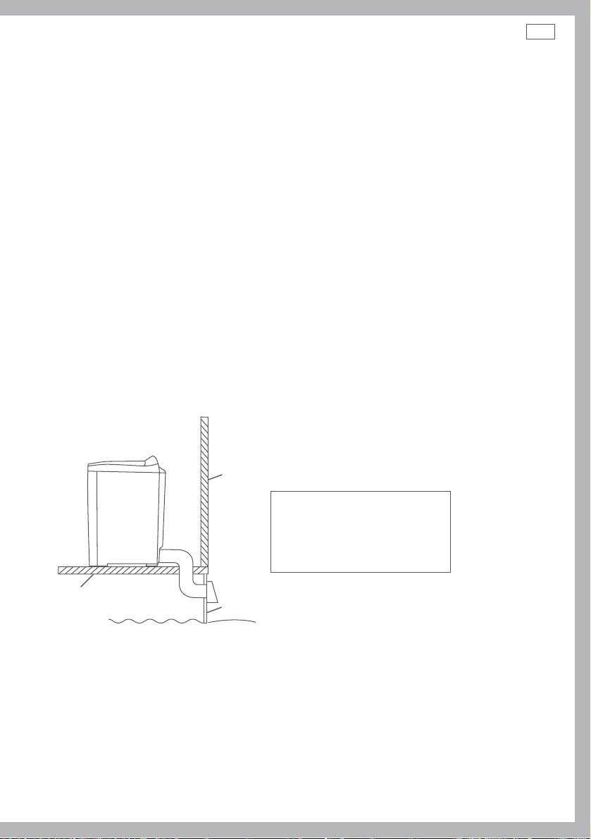
Mobile home installation
The installation of the dryer in a mobile home must conform to the Manufactured Home
Construction and Safety Standard Title 24 CFR, Part 3280 {formerly the Federal Standard for
Mobile Home Construction and Safety, Title 24 HUD (Part 280), 1975} for the United States or
Standard CAN/CSA – Z240MH for Canada.
When installing a dryer in a mobile home, provisions for anchoring the dryer to the floor must
be made.
A Mobile Home anchoring installation kit is available with instructions (see Accessories page 7).
Locate in an area that has adequate outside make up air (a minimum of 72 square inches of
unobstructed opening is required).
Mobile home installations must be exhausted to the outdoors with the exhaust duct
termination securely fastened to the mobile home structure, using materials that will not
support combustion.
The exhaust duct must not terminate beneath the mobile home. See the section on exhausting
for more information (refer to page 12).
The dryer must be
exhausted outside
11
enclosed area
floor
Fig.8 Exterior venting
outside
wall
The exhaust vent must be securely
fastened to a non-combustible
portion of the mobile home
structure and must not terminate
beneath the mobile home.
skirting
Page 14
12
Installation instructions
Venting
WARNING!
Fire Hazard
The dryer must be vented to the outdoors.
Use rigid or thick wall flexible metal exhaust duct only.
Do not use a plastic exhaust duct.
Do not use a metal foil exhaust duct.
Failure to follow these instructions can result in death or fire.
The dryer exhaust must be vented to the outdoors. This will prevent the build up of lint and
moisture in the room in which it is located and reduce the risk of fire.
Exhaust ducting products can be purchased from your local Appliance store or Hardware store.
Never use plastic or metal foil flexible duct. This ducting can kink, sag, be punctured, reduce
airflow, extend drying times and affect dryer operation.
A minimum of 4 inch (100 mm) thick wall flexible metal or rigid galvanised metal duct must be
used. Using ducts larger than 4 inches (100 mm) diameter may result in more lint accumulating.
In Canada, the exhaust duct must be 4.02 inches (102 mm) in diameter.
Using straight rigid metal ducting will minimize lint accumulation. Thick wall flexible metal
ducting may be used but care must be exercised to avoid sharp bends which may squash the
duct and cause blockages.
Use duct tape to secure joints. Do not use screws or any other fastening device which will
extend into the duct, as they will collect lint.
Keep ducting as short and straight as possible. Do not exceed the maximum exhaust duct
lengths stated later in these installation instructions. The total length of flexible metal duct used
should be no longer than 94.5 inches (2.4 m).
Do not vent the dryer into any other duct, chimney or gas vent because accumulated lint and
other material is a potential fire hazard. Do not vent the dryer into any ceiling, attic, crawl space,
under-floor space, wall cavity, window well or any other concealed cavity that will accumulate lint.
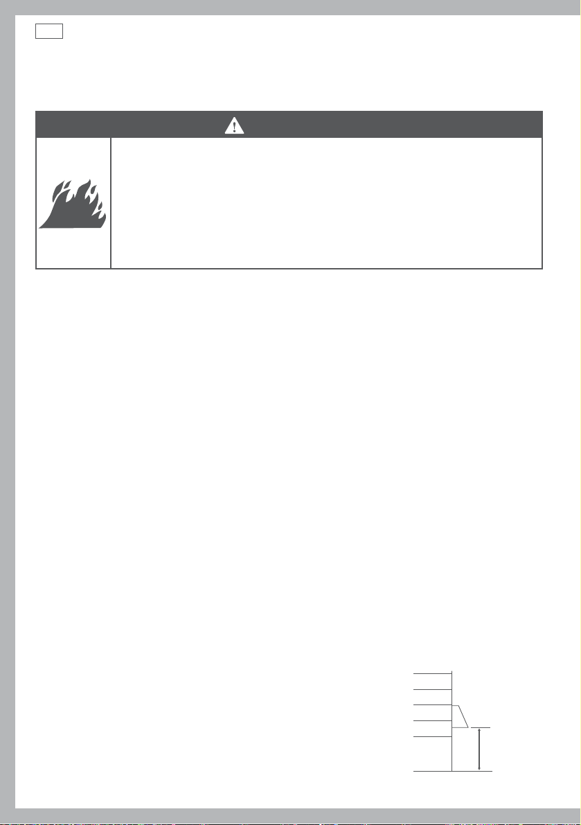
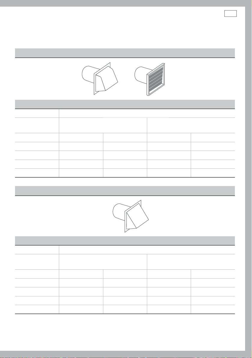
Fit an exhaust hood with a swing-out damper to the outside end
of the exhaust duct to prevent back drafts and entry of wild life.
Never use exhaust hoods with a magnetic damper. The hood
should have at least 12 inches (305 mm) clearance between the
bottom of the hood and the ground or other obstruction. The
hood opening should point down. Never install a screen over the
exhaust outlet.
Fig.9 Exhaust hood minimum
ground clearance
12” (305 mm)
Page 15
Installation instructions
Venting
To reduce condensation, insulate any ducting which passes through unheated areas. Slope the
duct gently downwards to the hood, to drain condensation and reduce lint build up. Avoid sag
or loops in the duct as they may collect and store water and accumulate lint.
Before using an existing exhaust duct system for a dryer ensure that:
No plastic or other potentially combustible duct or flexible metal foil ducting has been used.
The duct is not pierced, kinked or crushed.
The duct does not exceed the maximum recommended length for the new dryer.
The exhaust hood damper opens and closes freely and with sufficient movement.
Static pressure in the exhaust ducting does not exceed 1 inch of water column (250Pa), or is not
less than 0 inches of water column (ie. negative pressure), when measured with a manometer
in the 6 inches of the duct nearest the dryer, with the empty dryer running on Air Dry (no heat)
setting.
The exhaust duct system meets all relevant local, state and national codes.
All ducting should be inspected and cleaned at least once a year to remove accumulated lint.
Frequently check that the damper on the exhaust hood moves sufficiently and opens and
shuts freely.
Mobile Home Installations
A Mobile Home Installation Kit is available (see Accessories page 7).
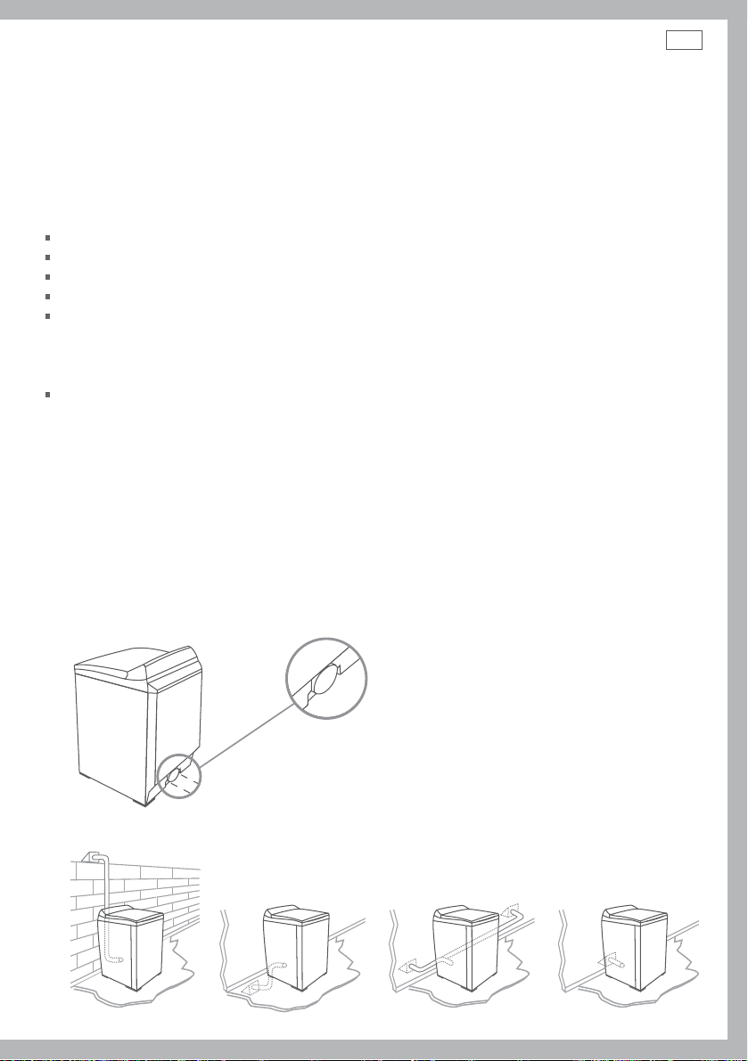
13
Determine vent duct length
This dryer can only be vented from the rear and must be exhausted to the outdoors.
Fig.10 Rear venting only
Different types of vent arrangements are shown below.
Fig.11 Venting options
Page 16
14
Installation instructions
Venting
Choose a route that will provide the straightest and most direct path outdoors. Plan the
installation to use the fewest number of elbows and turns.
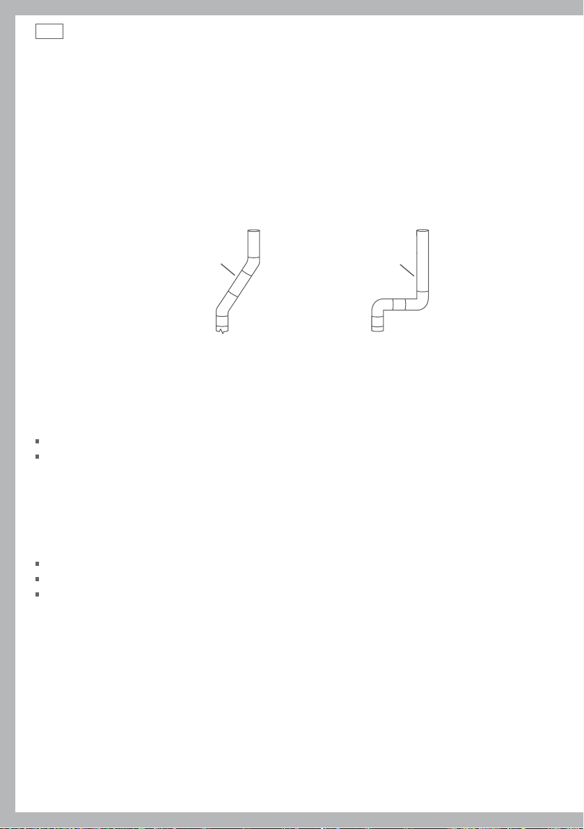
When using elbows (rigid duct) or making turns (thick wall flexible metal duct), allow as much
room as possible. With thick wall flexible metal duct bend duct gradually to avoid kinking and
avoid 90˚ turns.
recommended acceptable
Fig.12 Duct configurations
Maximum length of exhaust duct
The maximum length of the exhaust duct system depends upon:
The type of ducts (rigid or thick walled flexible metal).
The number of elbows or bends used.
1
Refer to the exhaust duct length chart that matches your hood type for the maximum duct
lengths you can use. Do not use duct runs longer than specified in the exhaust duct length
charts (refer to page 15).
Exhaust duct systems longer than specified will:
Accumulate lint creating a potential fire hazard.
Shorten the life of the dryer.
Reduce performance, resulting in longer drying times and an increased energy usage.
2
Determine the number of elbows/bends you will need.
3
In the column listing the type of metal duct you are using (rigid or thick wall flexible metal), find
the maximum length of metal duct on the same line as the number of elbows/bends to be used
(refer to page 15).
Page 17
Installation instructions
Maximum length of exhaust duct
Preferred 4” Hoods
When you have a 4” (100 mm) Hood
Maximum length of 4” diameter metal duct.
Number of 90˚
elbows/bends
0 64 ft 19.5 m 8 ft 2.4 m
1 54 ft 16.5 m 8 ft 2.4 m
2 44 ft 13.4 m 8 ft 2.4 m
3 35 ft 10.6 m 8 ft 2.4 m
4 27 ft 8.2 m 8 ft 2.4 m
Rigid
Thick Wall Flexible Metal
(fully extended)
15
Acceptable 2 ½” Hood
When you have a 2 ½” (60 mm) Hood
Maximum length of 4” diameter metal duct.
Number of 90˚
elbows/bends
0 58 ft 17.6 m 8 ft 2.4 m
1 48 ft 14.6 m 8 ft 2.4 m
2 38 ft 11.5 m 8 ft 2.4 m
3 29 ft 8.8 m 8 ft 2.4 m
4 21 ft 6.4 m 8 ft 2.4 m
For exhaust systems not covered by the exhaust duct length charts (such as multiple unit
hook-ups, plenums, and power-assist fans), call our Customer Care Center:
TOLL FREE 1.888.9.FNP.USA (1.888.936.7872).
Rigid
Thick Wall Flexible Metal
(fully extended)
Page 18
16
Installation instructions
Alternative installation for close clearances
Venting systems come in many varieties. Select the type best for your installation.
A close-clearance installation is shown.
swivel collar
sections separate,
fittings can face
same or opposite
wall connection
swivel collar
Extra long
band–clamp
for dryer
connection
Fig.13 Close-clearance installation Fig.14 Installation configuration
telescoping
sections
beveled edges
allow corner
installations
The maximum length using a 2” x 6” (50 mm x 150 mm) rectangular duct with two elbows and a
2 ½” (63 mm) exhaust hood is 8 ft (2.4 m).
Refer to the venting system kit manufacturers instructions.
Page 19
Installation instructions
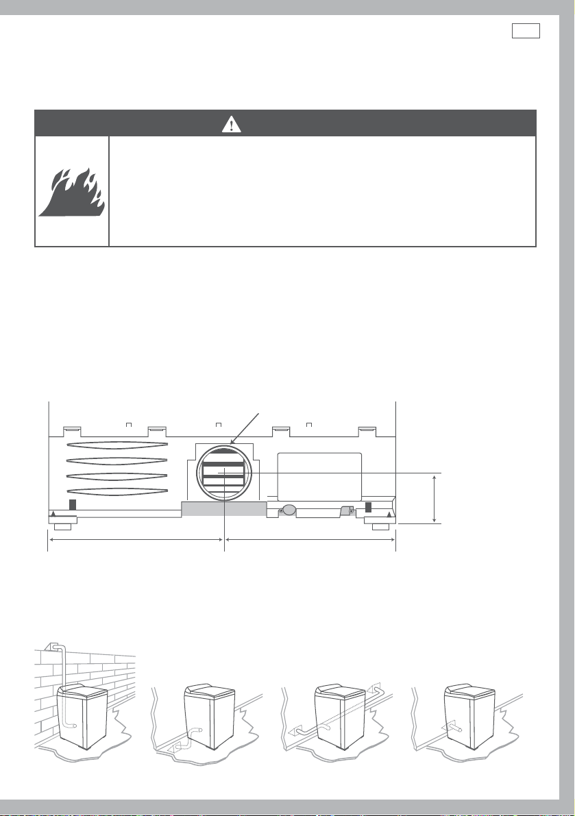
Exhaust venting
WARNING!
Fire Hazard
Use heavy metal exhaust duct.
Do not use a plastic exhaust duct.
Do not use thin metal foil exhaust duct.
Failure to do so can result in death or fire.
1
Read the exhaust section (pages 12 – 15) before installing the exhaust system to determine the
maximum allowable exhaust duct length.
Do not use sheet metal screws when assembling ducting. Always use suitable duct tape.
Never use plastic or thin metal foil flexible exhaust material.
2
The exhaust outlet is located close to the center of the rear of the dryer. Make sure you join the
exhaust duct to the dryer with duct tape only. This will prevent lint and dust from escaping from
the dryer and exhaust system.
Exhaust outlet
17
Does not include
4 ⁄”
foot height
(111 mm)
13 ⁄” (352 mm)
Fig.15 Exhaust venting dimensions
3
The exhaust vent can be routed up, down, left, right or straight out the back of the dryer.
Refer to diagram.
Fig.16 Venting options
13 ⁄” (333 mm)
Page 20
18
Installation instructions
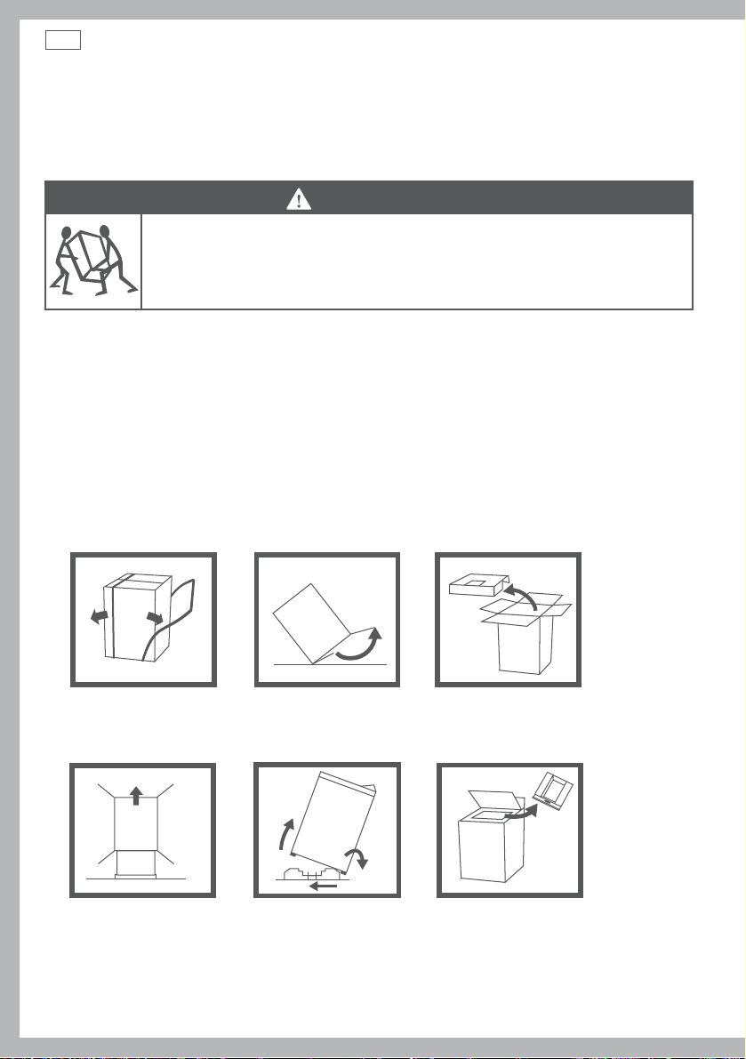
Installation
Parts and literature are packaged inside the dryer drum.
WARNING!
Excess Weight Hazard
Use two or more people to move and install the dryer.
Failure to do so can result in back or other injury.
Only remove the packaging at the customer’s premises. This will ensure the appliance arrives in
pristine condition and reduces the risk of damage when transporting to the customer’s home.
Unpacking
Make sure dryer is in a suitable location for installation.
Consider installing the dryer before the washing machine in a side by side installation, this will
allow better access to electrical and exhaust connections.
Remove packaging
1.
1. Remove straps.
4. 5.
4. Remove the carton
by lifting it off the
product (do not cut
the carton off ).
2. 3.
2. Unfold the bottom
flaps on the carton.
Tilt
5. Remove the basepacker
by tilting the product
back and walking the
product off it.
Walk
off
Slide out
3. Unfold the top flaps on
the carton, remove top
packer.
6.
6. Remove the drum
packer and the tape
from the lint collector
bucket in the drum.
Page 21
Installation instructions
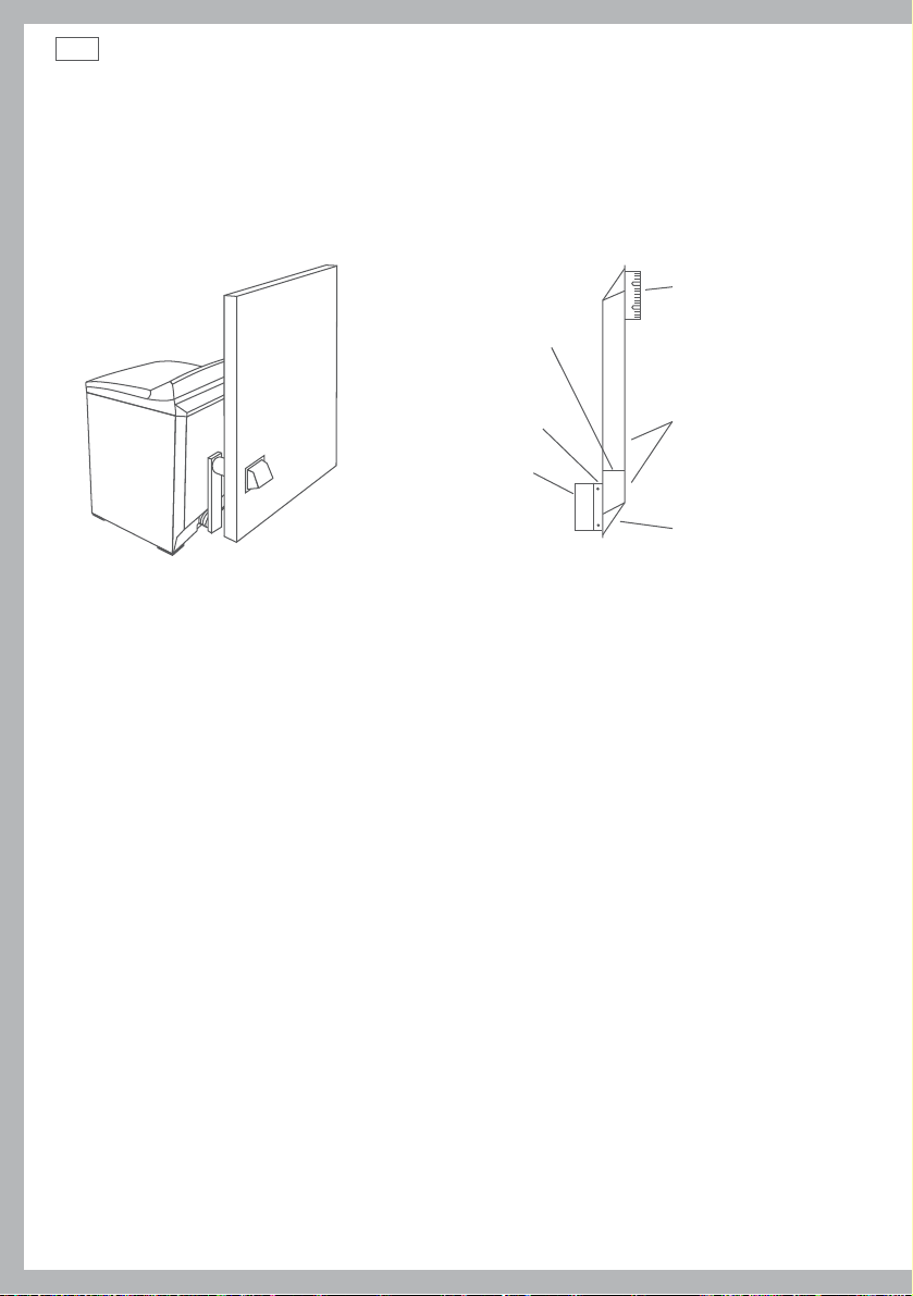
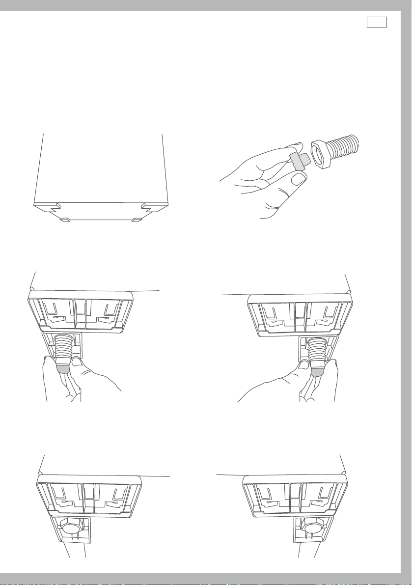
Fitting the front feet
Note: Dryer is usually supplied with feet fitted and protruding the correct distance.
1
Tilt the dryer back using a hand trolley and making sure the trolley and dryer are secure.
2
Fit a rubber insert to each plastic foot as shown.
Fig.17 Inserting rubber inserts
3
Screw the feet into the foot retainers on the left hand and right hand sides as shown.
19
Fig.18 Adjusting feet
4
Screw both feet in so they protrude ½” (12 mm) below the bottom of the wall on the foot retainers.
Fig.19 Final foot position
Page 22
20
Installation instructions
Grounding instructions for gas and electric dryers
WARNING!
Electrical Shock Hazard
Make sure appliance is wired or plugged into a grounded outlet.
Do not use an adaptor.
Do not use an extension cord.
Failure to follow these instructions can result in death, fire, or electrical
shock.
WARNING!
Electrical Shock Hazard
Check with a qualified electrician or serviceperson if you are in doubt as to
whether the appliance is properly grounded.
Do not modify the plug if it will not fit the outlet.
Have the proper outlet installed by a qualified electrician.
Failure to follow these instructions can result in death, fire, or electrical
shock.
Grounding for a cord-connected appliance
This appliance must be grounded. In the event of malfunction or breakdown, grounding will
reduce the risk of electric shock by providing a path of least resistance for electric current.
When this appliance is equipped with a cord having an equipment-grounding conductor and a
grounding plug, the plug must be plugged into an appropriate outlet that is properly installed
and grounded in accordance with all local codes and ordinances, or in their absence, with the
National Electrical Code ANSI/NFPA 70, or the Canadian Electrical Code, CSA C22.1. Do not cut or
remove the grounding prong from this plug.
Improper connection of the equipment-grounding
conductor can result in a risk of electric shock. Check with
WARNING
Refer to pages 21 – 27 for wiring details for electric dryers.
a qualified electrician or service representative if you are in
doubt as to whether the appliance is properly grounded.
Page 23
Installation instructions
21
Electrical requirements for electric models only
WARNING!
Electric Shock Hazard
Use a new UL approved 30-ampere power cord or direct wire cable.
Use a UL approved strain relief.
Disconnect power before making electrical connections.
Connect neutral wire (white or center wire) to center terminal.
On all four wire installations remove the grounding link and connect the
ground wire to the green ground connecting screw.
Connect remaining 2 supply wires to remaining 2 terminals.
Securely tighten all electrical connections.
Failure to do so can result in death, fire, or electrical shock.
Note: The wiring diagram is located in the control console.
The dryer must be plugged into or connected to an individual branch circuit, do not use an
extension cord.
The power supply must be 220/240V or 208V, 60 Hz approved alternating current electrical
service. The electrical service requirements can be found on the data label that is located on the
splash back. A 30-ampere fuse or circuit breaker is required on each of the lines.
If a power cord is used, the cord must be plugged into a 30-ampere receptacle.
The power cord is NOT provided with U.S. electric model dryers.
This dryer is supplied with the cabinet grounded through the neutral on the terminal block.
If the dryer is to be installed in (1) a new branch circuit installation, (2) a mobile home, (3) a
recreational vehicle, (4) an area where local codes do not permit grounding through the neutral
conductor, the appliance grounding link must be removed and a 4-wire power cord/cable or a
separate grounding wire must be used.
Do not reuse a power supply cord/cable from an old dryer. The power cord/cable electric supply
wiring must be retained at the dryer cabinet with a suitable UL listed strain relief.
208V requirements
If your power supply is 208V 60 Hz, a new element kit must be fitted by a qualified electrician or
service representative (see Accessories page 7 for kit part number).
Page 24

22
Installation instructions
Power supply cord requirements for U.S.A (for electric models only)
Only a UL listed power-supply cord kit a suitable length for the installation and rated 120/240 V
min, 30 A and marked with use for clothes dryers shall be used.
This shall have ring terminals to connect to the dryer.
The UL-rated strain relief included with it shall be suitable for a 1 /” (28.5 mm) hole.
Fig.20 UL listed power-supply cord
If your outlet looks like this Choose this power supply cord
3 wire
4 wire
Connecting by direct wire
Power supply cable must match power supply (4-wire or 3-wire) and be:
Flexible armoured or non-metallic sheathed copper cable (with ground wire). All currentcarrying wires must be insulated.
10 gauge AWG solid copper wire (do not use aluminium wire).
Suitable length for the installation.
A UL approved strain relief must be used.
Grounding for a direct wired appliance
This appliance must be connected to a grounded metal permanent wiring system, or an
equipment grounding conductor must be run with the circuit conductors and connected to the
equipment-grounding terminal on the appliance.
Page 25

Installation instructions
Electrical connections (electric models only)
Please read Electrical requirements and grounding instructions on pages 20 – 21 first.
Electric models of the dryer are manufactured for a 3-wire connection system. The dryer frame
is grounded by a link to the neutral conductor on the dryer terminal block. If local codes do
not permit grounding through the neutral, the grounding link from the terminal block must be
removed and a separate ground wire must be used.
The grounding link on the dryer must be removed for all 4-wire installations including new,
remodelled construction, or mobile homes.
These Electrical Connection instructions provide for installing the dryer in the following
situations:
3-wire connection where local codes permit grounding through the neutral.
3-wire connection plus separate grounding connector where local codes do not permit
grounding through the neutral.
4-wire connection.
Each of the above connections can be made with an approved power supply cord or by direct
wiring. Each connection instruction identifies the appropriate Power Supply Cord and covers
requirements for direct wiring.
For 3-wire connections by power cords
3-wire power supply cord must have three 10 AWG copper wires and match a 3-wire receptacle
of NMEA Type10-30R.
23
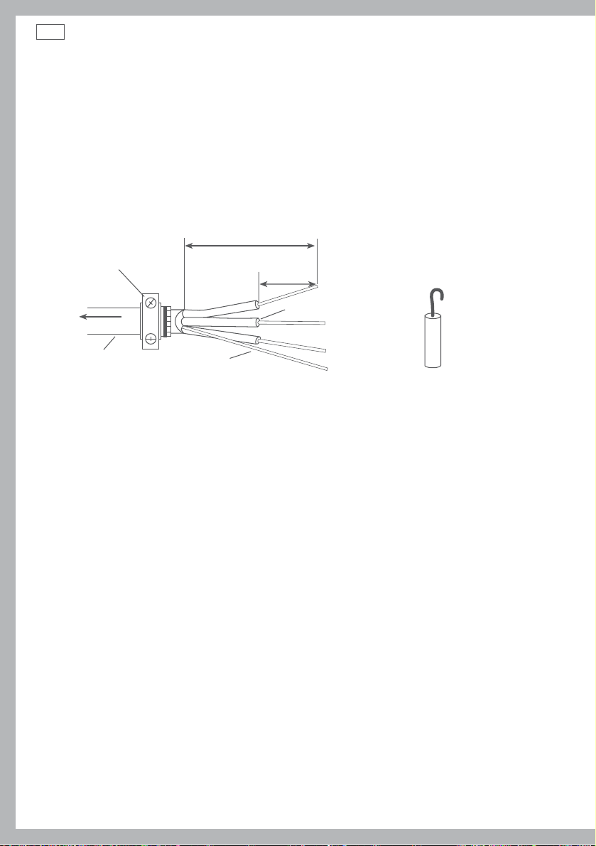
For 3-wire connections by direct wiring
Three-wire with ground
wire: Bare wire cut short.
Wire not used. Dryer is
¾” UL-listed
strain relief
to disconnect
box
10-gauge, 3-wire or,
10-gauge, 3-wire with
ground wire (Romex)
grounded through neutral
or separate grounding
Fig.21 Wiring 3-wire connections
4 ¼”
1” of wires
stripped of
insulation
NEUTRAL wire
(white or center)
Strip 4 ¼” of outer covering from end of
cable. Strip insulation back 1”. If using
3-wire cable with ground wire, cut bare
wire even with outer covering.
Shape ends of wire
into a hook.
Page 26
24
Installation instructions
Electrical connections (electric models only)
For 4-wire connections by power cords
4-wire power supply cord must have four 10 AWG copper wires and match a 4-wire receptacle
of NMEA Type14-30R. The fourth wire (ground conductor) must be identified by a green cover
and the neutral wire by a white cover.
For 4-wire connections by direct wiring
¾” UL-listed
strain relief
to disconnect
box
10-gauge, 3-wire with
ground wire (Romex)
4 ¼”
1” of wires
stripped of
insulation
NEUTRAL wire
(white or center)
bare ground wire
Fig.22 Wiring 4-wire connections
Strip 4 ¼” of outer covering from end of
cable. Strip insulation back 1”.
Shape ends of wire
into a hook.
Page 27

Installation instructions
3-wire connections
For use where local codes permit grounding through the Neutral wire.
Use approved 3-wire Power Supply Cord or a 3-wire Cable for Direct Wiring as described on
page 23.
1
Remove the terminal block cover plate.
2
Insert the power cord with a UL listed strain relief through the hole provided in the cabinet near
the terminal block. Do not tighten strain relief screw until wiring connections are complete.
Note: a strain relief must be used.
25
2
strain relief
screws
Fig.23 Inserting the power cord
3
Loosen or remove the center terminal block screw. Connect the neutral wire (center) of the
strain relief
clamp sections
power supply cord to the center terminal screw of the terminal block. Tighten screw.
4
Connect the other wires to the upper and lower terminal block screws marked with the letter L.
Tighten screws.
4
3
Fig.24 Connecting the wires
5
Refit terminal block cover by inserting the two tabs first on the rear panel of the dryer. Secure
4
cover with securing screw.
6
Tighten strain relief screws.
56
Fig.26 Tightening strain relief screwsFig.25 Refitting terminal block cover
Page 28

26
Installation instructions
3-wire connections plus separate grounding connector
For use where local codes do not permit grounding through the Neutral wire.
Use approved 3-wire Power Supply Cord or a 3-wire Cable for Direct Wiring as described on page 23.
A separate 10AWG copper grounding wire is required.
1
Remove the terminal block cover plate.
2
Insert the power supply cable with a UL listed strain relief through the hole provided in the cabinet
near the terminal block. Do not tighten strain relief screw until wiring connections are complete.
Note: a strain relief must be used.
2
strain relief
screws
Fig.27 Inserting the power cord
3
Remove center terminal block screw.
4
Remove appliance ground link by removing the ground connector screw (Green screw).
5
Connect a separate copper ground wire (green with yellow stripe) using the ground connector
screw (Green screw). Make sure a ring terminal is used when connecting the ground wire and that
the wire is firmly secured to an adequate grounding path.
strain relief
clamp sections
3
Note: If the appliance is
moved back to a 3-wire
4
installation the ground
link must be refitted.
Remove link
Fig.28 Connecting the wires
6
Connect the neutral wire (center) of the power supply cord to the center terminal screw of the
terminal block. Tighten screw.
7
Connect the other wires to the upper and lower terminal block screws marked with the letter L.
Tighten screws.
8
Refit terminal block cover by inserting the two tabs first on the rear panel of the dryer and secure
cover with securing screw.
9
Tighten strain relief screws.
9
grounding wire
It is recommended that a qualified electrician
determine that the ground path is adequate
8
Fig.29 Refitting terminal
block and tightening screws
7
6
5
7
Page 29

Installation instructions
4-wire connections
Use approved 4-wire Power Supply Cord or a 4-wire Cable for Direct Wiring as described
on page 24.
1
Remove the terminal block cover plate.
2
Insert the power supply cable with a UL listed strain relief through the hole provided in the cabinet
near the terminal block. Do not tighten strain relief screw until wiring connections are complete.
Note: a strain relief must be used.
2
strain relief
screws
3
Remove center terminal block screw.
4
Remove appliance ground link by removing the ground connector screw (green screw).
Remove link
5
Connect ground wire (green) of the power supply cord to the ground conductor green screw.
Fig.30 Inserting the power cord
3
4
Note: If the appliance is moved back to a 3-wire
installation the ground link must be refitted.
Fig.31 Removing screws
Tighten screw.
6
Connect the neutral wire (white) of the power supply cord to the center terminal screw of the
terminal block. Tighten screw.
7
Connect the red wire and black wire to the upper and lower terminal block screws marked with
the letter L. Tighten screws.
7
6
5
Fig.32 Connecting wiring
strain relief
clamp sections
27
7
8
Refit terminal block cover by inserting the two tabs first on the rear panel of the dryer and
secure cover with securing screw.
9
Tighten Strain Relief screws.
8
Fig.33 Refitting terminal block and screws
9
Page 30
28
Installation instructions
Gas requirements (gas models only)
The installation must conform with Local Codes, or in the absence of Local Codes, to the
National Fuel Gas Code ANSI Z223.1/NFPA 54 or the Canadian Natural Gas and Propane
Installation Code, CSA B149.1.
WARNING!
Explosion Hazard
Installations must be performed by a qualified or licensed contractor,
plumber, or gasfitter qualified or licensed by the state, province, or region
where this appliance is being installed.
Use a new AGA or CSA approved gas supply line.
Install a shut-off valve in an accessible place.
Only use a gas shut-off valve approved for use within the state, province, or
region where this appliance is being installed.
Securely tighten all gas connections.
If connecting to LP Gas, have a qualified person make sure gas pressure
does not exceed 13” (330 mm) water column.
Failure to follow these instructions can result in death, explosion, or fire.
Gas type
Your dryer must have the correct burner for the type of gas in your home. Burner information
is located on the rating plate located on the rear of the console. If this information does not
agree with the type of gas available in your home, contact your local Fisher & Paykel supplier or
service center.
Natural gas
This dryer is supplied ready for use with Natural Gas.
It is design certified by UL International for LP (Propane or Butane) Gases with the appropriate
conversion.
LP gas conversion
If the dryer is to be operated on LP (Liquid Propane or Butane) Gas, the dryer must be
converted. To do so, use only the approved Fisher & Paykel conversion kit listed in Accessories
on page 7. Do not use with a different gas without consulting the serving gas supplier.
The dryer must be converted for safe and proper performance by qualified service or installation
personel.
Conversion kits for Natural and LP Gas are available from your local Fisher & Paykel Dealer
(see Accessories page 7). If other conversions are required, check with your local gas utility for
specific information concerning conversion requirements.
Page 31
Installation instructions
Connecting gas to your dryer (gas models only)
Use compound or thread tape appropriate to the gas type that is to be used (Natural or LP Gas),
on the male threads of all non-flared connections.
Never use an open flame to test for gas leaks.
This dryer will operate satisfactorily up to altitudes of 6500 ft (2000 m) above sea level at the
BTU rating indicated on the model/serial plate. Burner input adjustments may be required if
operating above this elevation.
The dryer must be disconnected from the gas supply system during any pressure testing.
Gas ignition
This dryer has an automatic ignition system to ignite the burner. There is no pilot flame burning
in this dryer.
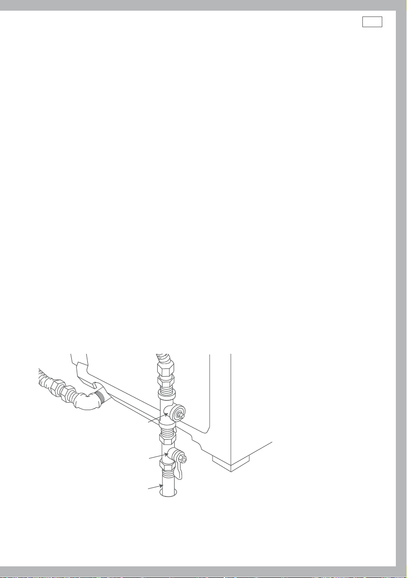
Connecting to the gas supply
1
The gas supply line should be ½ inch.
2
An individual manual shut-off valve must be installed on the gas supply line within 6 ft (1.8 m)
of the dryer, in accordance with the National Fuel Gas Code ANSI Z223.1/NFPA 54 for the United
States or in accordance with the B149.1 Natural Gas and Propane Installation Code for Canada.
3
An ⁄ inch NPT plugged tapping must be installed to allow the gas inlet pressure to be checked.
It must be accessible for the test gauge connection and immediately upstream of the gas
connection to the dryer.
29
⁄” NPT plugged tapping
Gas shut–off valve
⁄” NPT gas supply line
Fig.34 Connecting the gas supply
Page 32

30
Installation instructions
Connecting gas to your dryer (gas models only)
4
A listed connector in compliance with ANSI Z21.24/CSA6.10 must be used to connect the dryer
to the gas supply.
5
If flexible tubing is used, an elbow should be installed on the pipe at the back of the dryer for
the flexible tube to be connected to. This will minimize damage to the tube when the dryer is
moved back. Use a flexible tubing connection kit that has designed for use on a clothes dryer.
This kit should have the unions necessary to join to the ends of the tubing. Be sure to follow all
instructions supplied with the kit.
6
Copper tubing should not be used for Natural Gas and if used for LP Gas, it must be LP Gas
compatible.
7
Disconnect and discard old flexible tubing.
8
The gas pipe that comes out of the rear of your dryer has on it a ⁄” NPT male thread. Remove
the protective cap and apply sealing compound or tape to the thread. Thread sealant should be
appropriate for the type of gas to be used.
Apply thread
sealant
Remove cap
Fig.35 Preparing for gas tubing connection Fig.36 Connecting the gas tubing
⁄” NPT pipe thread
Elbow required for
flexible tubing
Completing the connection
9
Use wrenches to tighten all joints but do not over tighten.
10
Open the gas supply valve and check all joints by brushing on a non-corrosive leak-detecting
solution. Bubbling will indicate a leak. If any leaks are found, close the valve immediately and
correct the leaks. Retest and repeat until no leaks are found.
Page 33
Installation instructions
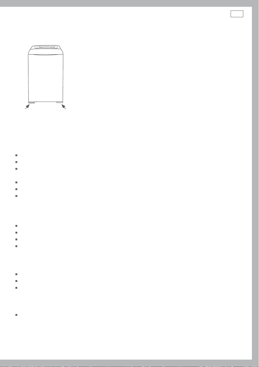
Levelling the dryer
Fig.37 Levelling the dryer
Check the dryer is level, and make necessary adjustments to the front levelling feet.
The rear levelling feet are self adjusting.
Final installation check list
Check that:
No plastic or flexible metal foil is used in the exhaust ducting.
Exhaust is rigid ducting or thick wall flexible metal ducting.
All joints in the ducting are made with duct tape. It must not be connected with screws or other
fastening devices which extend into the inside of the duct.
Ducting is clean and is connected to the dryer.
Inserts are fitted to the two front feet.
Dryer is level across the front.
31
Additionally for electric dryer models only, check:
If installation is 208V, special element kit has been fitted (see page 21).
Dryer is plugged or directly wired into an approved fitting and is properly grounded.
Dryer starts, heats, cools and shuts off.
Customer has been shown how to use the dryer.
Additionally for gas dryer models only, check:
Dryer is plugged into an approved fitting and is properly grounded.
All fittings in the gas line are tested for leaks.
Exhaust temperature increases, to confirm ignition has occurred.
– If ignition does not occur initially, it may be due to air in the gas line or low voltage power supply.
– The gas regulator valve may fail to open if the power supply falls below 105 Volts.
– If the gas fails to flow or does not ignite, the dryer will automatically switch off.
Customer has been shown how to use the dryer.
Note: All dryers have a drum reversal feature to reduce clothes tangle. Throughout the drying
cycle the motor will run for four minutes, then stop and run in the opposite direction for forty
seconds before reversing again.
Page 34

32
The rst time you turn your dryer on
WARNING!
Electric Shock Hazard
Read and follow the Important safety instructions outlined in this User
Guide before operating this appliance, pages 3 – 6.
Failure to do so can result in death, electric shock, fire or injury to persons.
Close supervision is necessary if this dryer is used by or near children. Do not allow children to
play inside, around or with this dryer or any other appliance.
Customizing your AeroSmart dryer
The first time that you turn your dryer on an initial set-up mode will be initiated. This is to
ensure that your AeroSmart is customized for your individual needs. The set-up mode will
prompt you to select the language that you would prefer your AeroSmart dryer to use.
JH:C<A>H=
Using the SCROLL buttons, scroll to the language that you would like your dryer to use. Once
the language icon has been highlighted, press SELECT to confirm your choice. Your dryer will
now use this language, and the initial set-up prompt will not appear again.
If you wish to change your language choice at any time, you can do this by simply selecting the
LANGUAGE option in the SETTINGS MENU (please refer to pages 53 and 54).
Page 35
Smart loading
The new ergonomic design of this dryer means less bending. Simply
move clothes from the washer to the dryer with
minimal effort.
Superior clothes care
Superior clothes care is accomplished by an efficient high airflow
fan and careful heat control. The AeroSmart dryer provides the right
heat for temperature sensitive delicate articles while still efficiently
drying more robust regular and denim loads.
Reverse action tumbling
The drum reverses regularly, so your clothes dry more evenly
without roping or tangling.
Features
33
Lint bucket
The lint filter is automatically scraped clean during the drying
cycle and the lint is deposited into the lint bucket. No touching
or scraping lint any more. Airflow is more efficient as it is never
restricted by a blocked filter.
Perfect with the Fisher & Paykel AquaSmart™ washer
The dryer combined with the AquaSmart™ washer’s superior spin
performance and quick cycle times will cut laundry turn around time
by up to one third, reducing the time you spend doing laundry.
Stainless steel drum
Being stainless steel, this drum is not only more hygienic, it’s also
more resilient and easier to keep looking good.
Page 36

34
Getting started quickly
Operating instructions
Sorting
For the best drying results, sort your clothes into similar types
that will take a similar time to dry (refer to Sorting page 37).
Loading
Ensure that clothes are loaded no higher than the top of
the transparent section of the lint bucket (refer to Loading
page 37).
Lint bucket
Before each cycle, check to see if the lint bucket needs to be
emptied. Empty the bucket before the lint reaches the top of
the transparent section (refer to Lint bucket page 38).
1 2 6
Fig.38 Maximum loading level
Empty before this
level is reached
Fig.39 Lint bucket
Fig.40 AeroSmart control panel
Page 37

Getting started quickly
Easy touch buttons and LCD screen
These buttons require only a gentle touch to activate.
1
Touch POWER to activate your AeroSmart dryer.
2
WRINKLE FREE – this light tells you when WRINKLE FREE mode is recommended, and the button
also allows you to activate the WRINKLE FREE mode manually. (refer to page 36).
3
The LCD display screen, located in the middle of the control panel, will display the cycle options
available (refer to page 41).
4
Use the SCROLL buttons to select the drying cycle that best suits your load (refer to page 41).
5
Use the SELECT/TICK button to confirm your selection. (For more information on how to alter
the cycle options refer to pages 40 – 41).
6
Ensure the lid is closed and touch START - your AeroSmart will automatically lock the lid and
close the drum. It will then start to tumble, automatically sensing the dryness of your load as
the cycle progresses (unless Timed Dry is selected).
To pause your AeroSmart dryer at any time, simply touch START/PAUSE.
3 4 5
35
Page 38
36
AeroSmart controls
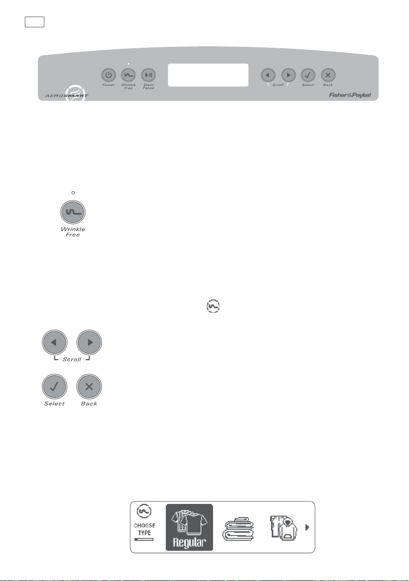
Easy touch controls
These smooth, easy clean buttons require only a gentle touch to activate. To scroll you need to
remove your finger to break contact and touch it again. Once you become accustomed to the
soft touch technology you will find it effortless to operate.
Wrinkle Free mode
This button activates or deactivates the WRINKLE FREE mode. This mode
minimizes the likelihood of wrinkles forming in clothes, if you are not
able to unload the dryer straight away. WRINKLE FREE rotates the drum
periodically after the cycle has finished. This tumbling action, combined
with blowing cool air through the clothes, helps garments to remain
wrinkle free.
WRINKLE FREE uses very little power and will continue for up to 24 hours or
until the dryer is paused or switched off. WRINKLE FREE can be selected on
any cycle.
The WRINKLE FREE symbol
active.
Scroll
The SCROLL buttons allow you to scroll between the drying options.
Select
Use the SELECT key to confirm your selected option and the BACK key to
cancel.
will appear on the screen when the mode is
The display screen
The display screen allows you to view the available cycles and modify options. It provides
feedback on what your AeroSmart dryer is doing and how long the cycle has to go, to keep you
informed throughout the process. The screen will also display messages to help you with the
overall running of your dryer.
Page 39

Using your dryer
Check the care labels inside the garments to determine whether the garment manufacturer
recommends tumble-drying.
37
Sorting
It is best that you sort your garments before placing them into the
dryer. Sort into loads of similar types, and loads that take similar times
to dry.
Heavier items (eg towels, t-shirts and flannel sheets) are best dried
separately from lightweight items (eg synthetics, poly-cotton sheets
and shirts). This prevents the possibility of some items becoming over-
dried whilst others are still damp. It will also help to extend the life of
your clothing and linen.
For best results match your load to the drying cycles offered to ensure the best drying of your
items (for more information on drying cycles available refer to page 43).
Drying your clothes as soon as the washer has finished will decrease the chance of wrinkles and
the chance of dye transfer from colored items to white items.
We recommend that articles of clothing with screen-printing are turned inside out to ensure the
screen-printing does not stick to the drum. Garments with hooks or zippers need to be fastened
and where possible turned inside out. Place undergarments in a net bag to provide protection
from other items in the load.
Fig.41 Sort before loading
Loading
Garments need to be loaded correctly to reduce the likelihood
of them wrinkling and to ensure the load is dried evenly. Make
sure there is ample room for the garments to tumble freely while
drying. Load in terms of the space the garments take up when
dry, rather than when they are wet.
The general rule is one wash load = one dryer load.
Only load the dryer up to the top of the transparent section of
the lint bucket. Loading any higher may result in uneven drying,
tangling, wrinkling and the dryer becoming overloaded.
It is a good idea to dry ‘permanent press’ type garments together
using the EASY IRON cycle, which has the WRINKLE FREE option
turned on. This will help reduce wrinkles and the need for ironing.
Load no higher
than here
Fig.42 Maximum loading level
Page 40
38
Using your dryer
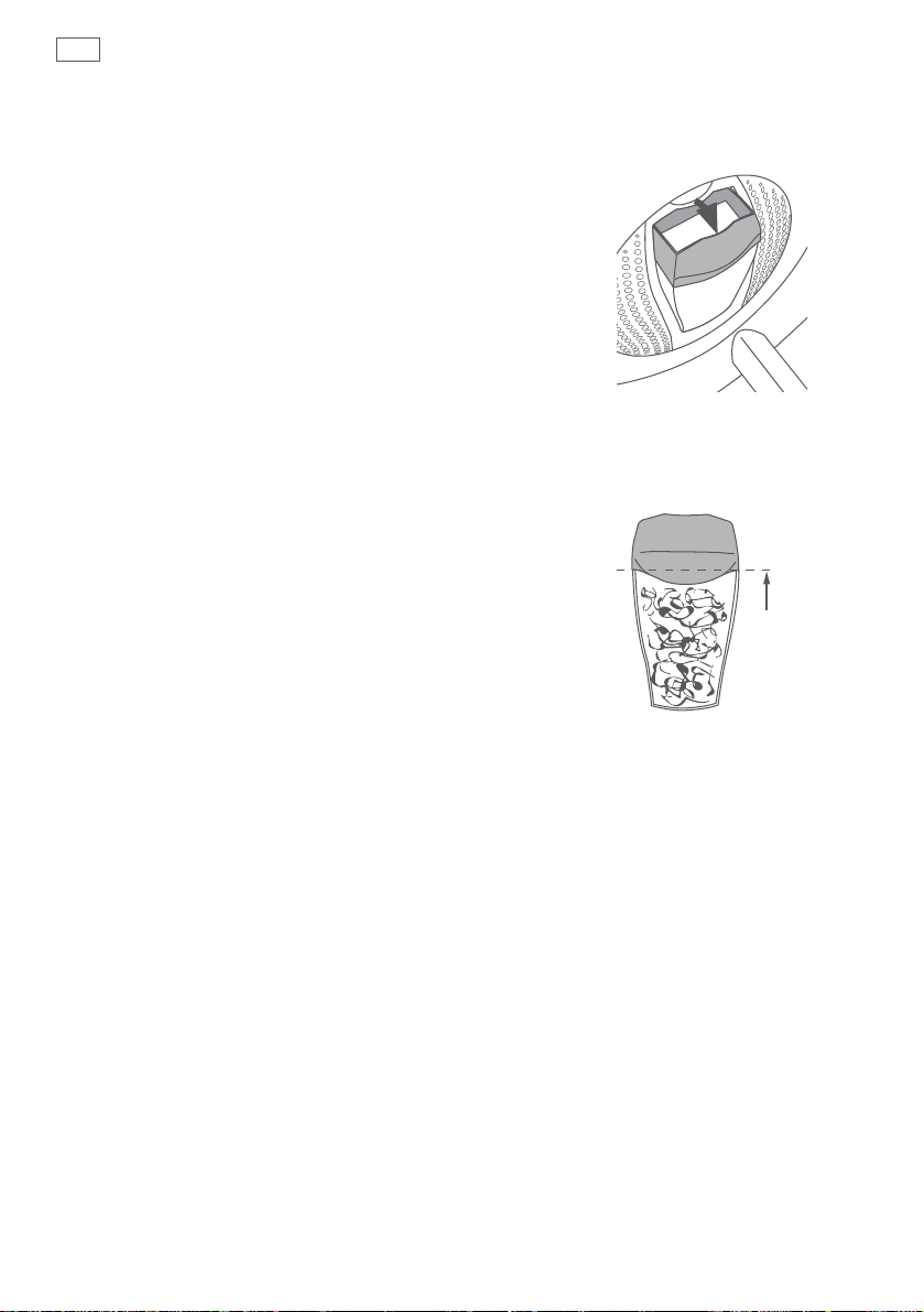
Lint bucket
The AeroSmart dryer’s lint removal system is unique.
Unlike other dryers, the AeroSmart dryer automatically
removes the lint for you, from the lint screen – all you
have to do is tip the lint out!
The lint filter is hidden behind the lint bucket. As the air
passes through this filter the lint is caught on the fine
mesh. Once the lint is about ⁄” (2 mm) thick it comes into
contact with a scraper which deposits it into the bucket.
This process is automatically performed every time lint
builds up on the filter.
Apart from the benefit of not having to scrape the lint
after every cycle, it also means the drying efficiency is not
affected by lint build-up during the drying cycle.
The lint bucket is located inside the dryer on the left-hand
side. You can remove it by gently pulling the handle and
lifting outwards. It slots easily back into place.
This lint bucket does not need to be cleaned as regularly
as other dryer’s lint filters. The lint bucket only needs to
be emptied before the lint reaches the top of the
transparent section.
Fig.43 Removing lint bucket
Empty before this
level is reached
Fig.44 Maximum lint level
Important!
It is important that you run your dryer with the lint bucket in place at all times.
Page 41

Choosing your drying cycle
Viewing the drying cycles
When you turn your AeroSmart dryer on, the main drying cycles will be displayed.
To view all 8 drying cycles, the Lifestyle cycles and menu options, use the arrow buttons to scroll
to the right.
39
Delicate Easy iron Casual Bulky Air dry Lifestyle MenuHeavySheets
To see the cycles explained in more detail please refer to pages 43 – 50.
To select a drying cycle
To select a drying cycle scroll along until your selection is highlighted then touch the SELECT
button. This will confirm your selection.
The drying cycle options will then be displayed for your chosen cycle.
Page 42

40
Changing the drying cycle options
1
Scroll to the option you wish to modify, by highlighting it and touching the SELECT button.
2
Scroll to the appropriate setting and press SELECT. This will highlight your choice to show you
that it has been selected.
3
You will then be given the option to save this modified option for future cycles or to just use it for
this one. If you select ‘save for future cycles?’, the machine will save the changed option for that
cycle only.
4
Press SELECT to select.
5
You will then return to the main cycle options screen.
6
Select START to begin drying, or press the START/PAUSE button.
Page 43

Changing the drying cycle options
Cycle options
To alter any of the Cycle Options explained below, please refer to page 40 for further instructions.
Auto Sensing
Auto sensing is automatically selected when your AeroSmart dryer is turned on.
AeroSmart’s internal computer automatically measures the moisture content of the
load and will turn off when it senses that the clothes have reached the designated
dryness level.
Using the Auto sensing capability of your dryer will ensure the best possible drying
result.
Timed Dry
Timed Dry allows you to select from three time periods – 20, 40 and 80 minutes. A
cooling period of 10 minutes is also included in the 80 and 40 minute cycles and a 5
minute cool down is included in the 20 minute cycle.
If you choose to select Timed Dry, please note that the dryer will not sense when
your clothes are dry. This may increase the chance of over-drying. We recommend
that you dry your clothes for a slightly shorter time than you think they need, or
check on them regularly (to avoid overdrying).
41
Auto sensing often provides the best drying results and can lead to lower energy
costs when compared to using the Timed Dry option.
Dryness Level (How dry?)
AeroSmart offers 5 dryness levels to choose from. This allows you to customise how
dry you would like your load to be at the end of the cycle, when using the Auto
sensing option.
Damp
Garments are
considered ‘moist’
Suitable for delicate,
light-weight fabrics, and
garments which you
may wish to iron dry
If items are still damp, or too dry at the conclusion of the cycle, next time try adjusting the
dryness level to customise it to your personal preference.
Damp+
(Damp/Dry)
Dry
Garments are
considered ‘dry’
Designed to
provide items
dry enough
to be worn
immediately
Dry+
(Dry/Extra Dry)
Extra Dry
Garments are
‘ex t ra dr y ’
Useful for drying
items that you
wish to store
(cupboard dry)
Page 44

42
Changing the drying cycle options
Temperature
AeroSmart offers 4 drying temperatures. Each drying cycle is set with a temperature
specific to the load type, to ensure the best possible fabric care for your clothes. If you
wish to use a different temperature simply select another drying cycle.
Air
no heat
Circulates room
temperature air
through the drum to
dry clothes without
heat
Remember to always check care labels on garments before placing them into the
dryer or selecting a drying temperature.
Low
gentle heat
This low heat provides
extra care for special
items
Medium
moderate heat
This moderate heat
provides efficient
drying for garments
that require a reduced
heat
High
maximum heat
This setting is the
maximum heat
setting to dry more
robust, everyday
items quickly
Drying cycle progress
As the cycle progresses the following symbols will be shown on the display screen to indicate
the progression of the cycle and which phase of the process AeroSmart has reached and the
dryness level selected. A progress bar will also appear once the cycle has started, to let you
know how the drying is progressing. For Time Dry cycles, Time To Go will also be displayed.
sensing dampness drying air drying cooling
Page 45
Changing the drying cycle options
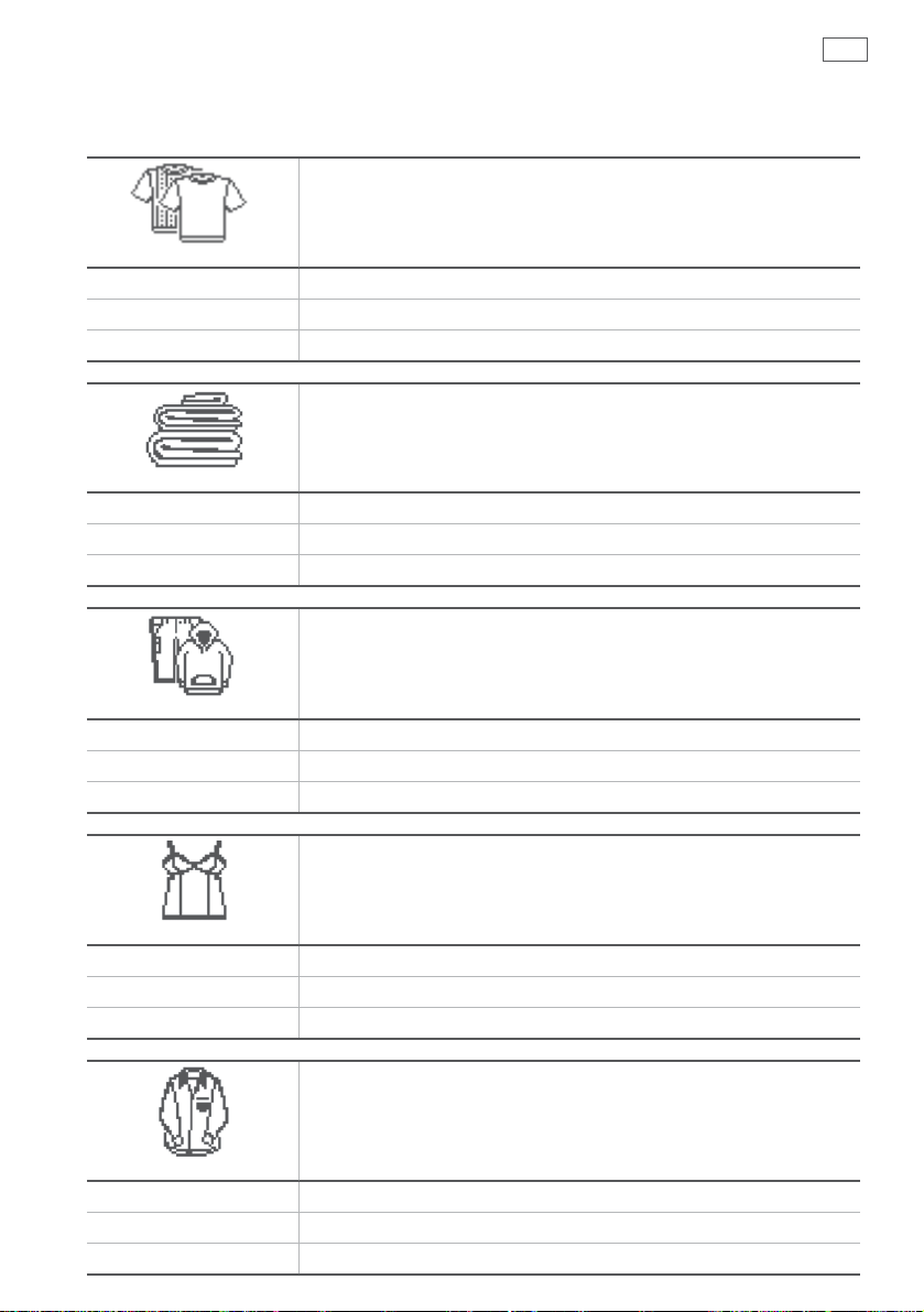
Drying cycles explained
Regular
A high heat cycle for rapid drying of everyday cottons. This cycle is
Regular
Drying Temp Medium+
Dryness Level Dry
Automatic Wrinkle Free Off
Bed Sheets
Drying Temp Medium+
Dryness Level Dry+
Automatic Wrinkle Free On
Heavy
Drying Temp High
Dryness Level Dry+
Automatic Wrinkle Free Off
suitable for most garments labelled “Tumble Dry”.
Bed Sheets
A high heat cycle, with WRINKLE FREE option, for the optimum
result for sheets.
Heavy
An extended, high heat cycle for heavy fabrics and denims to
ensure thick and bulky seams are thoroughly dried.
43
Delicate
Extra care for delicate heat sensitive items or fabrics
Delicate
Drying Temp Low
Dryness Level Dry
Automatic Wrinkle Free On
Easy Iron
Drying Temp Medium
Dryness Level Dry
Automatic Wrinkle Free On
recommending low heat.
Easy Iron
A medium heat cycle with WRINKLE FREE option, for extra care and
to reduce the likelihood of wrinkles forming. Ideal for any garments
that you may wish to wear immediately.
Page 46

44
Changing the drying cycle options
Drying cycles explained
Bulky
Six specialised drying cycles recommended for drying bulky items
Bulky
to choose from:
Comforter
Feather or Synthetic options
Blanket Throw
Jacket
For all bulky items:
It is important that you check the care label of any item carefully, to ensure it is suitable for
tumble-drying, before placing it into the dryer.
Check that the load sits no higher than the top of the lint bucket before you close the lid.
Comforters / Sleeping Bags / Pillows:
It is a good idea to check your comforter throughout the cycle to ensure even drying.
Reposition if necessary. If the comforter contains feathers place a heavy item (eg a towel tied in
a knot) to help fluff the feathers.
Blankets / Throws:
For best results include 4 – 5 medium sized towels in the dryer with the blanket for cushioning.
This will help to reduce shrinkage from over tumbling. When drying more than one blanket,
check that there is enough room for them to tumble easily. At the end of the cycle remove the
blanket, shake and if necessary stretch the blanket back to its original shape.
Pillows
Feather or Synthetic options
Sleeping (ZZz) Bag
Feather or Synthetic options
Important!
Dry blankets thoroughly to prevent mildew from forming.
Page 47
Changing the drying cycle options
Drying cycles explained
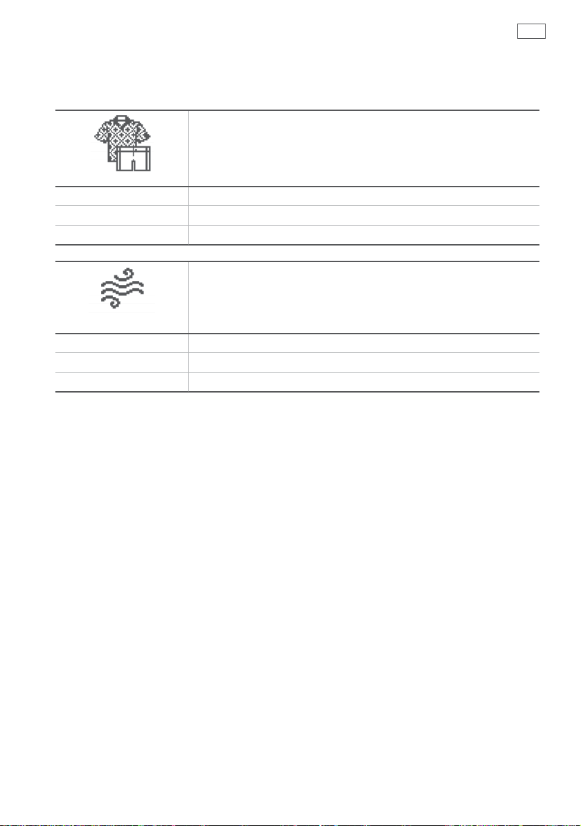
Casual
A medium heat cycle ideal for lightweight cottons and items
Casual
Drying Temp Medium
Dryness Level Dry
Automatic Wrinkle Free Off
Air Dry
Drying Temp No heat
Dryness Level Time Dry
Automatic Wrinkle Free Off
labelled “tumble with a medium heat”.
Air Dry
A cool cycle for drying items without heat. Perfect for airing clean
clothes or to freshen up garments that have been packed in a
suitcase or drawer.
45
Page 48

46
Lifestyle cycles
No experience necessary
Your AeroSmart dryer offers you a range of special Lifestyle cycles, to make drying even easier.
These cycles have been specifically designed by our laundry experts, with you in mind. We have
incorporated 70 years of laundry knowledge into 18 easy to use, preprogrammed drying cycles.
This allows you to let the dryer deal with some of the more tricky drying situations you may
encounter, ensuring that you get the same results as a laundry expert, without having to be one.
Lifestyle Cycles
Special
Care
Family Comforter Pillows Allergy Shirts Towels Soft Toys
Sport
Handwash Jeans Freshen Up Warm Up Dry Clean
Sportswear
Light
Sportswear
Heavy
Outdoor
Wear
Protection
Equipment
To access Lifestyle cycles:
1
Scroll though the drying cycles to reach the LIFESTYLE option.
2
Select LIFESTYLE, by touching the SELECT button, to the right of the screen.
3
Use the SCROLL buttons to scroll though the three Lifestyle categories.
4
Use the SELECT button to select a LIFESTYLE category.
5 Scroll through the Lifestyle cycles, touch SELECT to confirm your cycle choice, and then press
START.
Page 49

Lifestyle cycles
The Lifestyle cycles are presented in three distinct categories, to help you to access them
quickly and easily. The following pages explain the unique cycles that are located within these
categories, and how they might be of help.
Special Care
Special care offers 5 unique cycles to provide extra care for your garments.
Handwash
This is an extra gentle cycle for delicate items. Before placing any garments into
the dryer please check the care label carefully.
Jeans
The JEANS option has been designed for denims and jeans with thick seams that
require additional drying.
Not all jeans require the same type of drying. Some need a more gentle
approach to ensure they stay looking great. This is why we have created two
unique JEANS options:
WORKWEAR – a long, high heat cycle for sturdy everyday denims with bulky seams.
FASHION – a long, medium heat cycle to care for lightweight fashion jeans and
to minimize shrinkage.
47
Freshen Up
This cycle tumbles for 20 minutes without heat. It has been designed to freshen
clean clothes that have been stored in a cupboard, drawer or in a suitcase. It can
also be used to remove lint from clothing.
Warm Up
Warm Up heats clothes for 20 minutes so that they are warm to touch. Warm
your pyjamas before bed on a cold night or your towels while you are in the
shower. This cycle is not recommended for heat sensitive items.
Dry Clean
This cycle has been designed for use with in-dryer dry clean products. It uses a
medium heat for 40 minutes and the WRINKLE FREE option is activated. Follow
the manufacturer’s instructions carefully.
Important!
Ensure that the dry cleaning product is suitable for use in a domestic dryer.
Page 50

48
Lifestyle cycles
Family
Some common household laundry situations may require extra knowledge. We have created six
unique FAMILY cycles to help you with those tricky situations.
Comforter
Bulky items like Comforters can be tricky to dry due to their thickness. The
Comforter cycle has been designed to cope with bulky bedding. There are two
Comforter types to choose from – Feather or Synthetic.
Important!
It is important that before placing a comforter into the dryer you check the care
label to see if it suitable to be tumble dried.
Feather Comforters
This autosensing, low heat cycle is designed to ensure the best results for feather
Comforters. Feathers tend to bunch when washed, so we recommend that when
drying that you place a heavy item (eg a towel tied in a knot) in with the load to
help fluff the feathers up.
Synthetic Comforters
Synthetic Comforters are treated to an auto sensing, low heat cycle designed for
lighter, synthetic comforters. Check during cycle and reposition if necessary to
ensure even drying.
Important!
Check that the load does not sit higher than the top of the lint bucket before
starting the cycle.
Page 51
Lifestyle cycles
Family
Pillows
Choose from either Feather or Synthetic, low heat options to care for you pillows
during drying. Check throughout the cycle to ensure even drying. If pillows are
not completely dried at the end of the 40 minute period, repeat the Pillows cycle.
Allergy
This cycle has been developed to compliment the Allergy wash in the
AquaSmart™ washer. It is recommended for allergy sufferers, as well as for peace
of mind in times of family illness. Allergy uses a high heat to ensure that dust
mites and bacteria populations are decimated. It has been designed primarily
for sheets and everyday clothing, and is not recommended for garments that are
heat sensitive.
Shirts
This medium heat, autosensing cycle is ideal for business and dress shirts. The
WRINKLE FREE feature is automatically activated to reduce wrinkling and the
need to iron.
Towels
Towels is an autosensing, high heat cycle designed to ensure that towels and
thick seams are thoroughly dried.
49
Soft Toys
This gentle, cool, 20 minute blow dry takes care of the smallest
family member’s special friends. Repeat cycle if fur or body is not
completely dry.
Page 52
50
Lifestyle cycles
Sports
Outdoor activities can create some unique laundry challenges. We have created four helpful
cycles to quickly deal with these situations, with no thinking required.
Sportswear Light
This autosensing cycle uses a low heat to gently dry light synthetic
sportswear garments.
Important!
Use of fabric softener may block the performance enhancing features of hightech sportswear fabrics eg breathability and moisturewicking. Check the care
label before drying.
Sportswear Heavy
This extended autosensing, high heat cycle takes care of durable heavy
cotton sportswear garments with thick and bulky seams.
Outdoor Wear
Outdoor wear provides a cool cycle ideal for drying high performance
fabrics and outdoor items eg waterproof jackets. Please check the care
label first.
Protection Equipment
This 40 minute, low heat cycle gently dries padded sports protection
items eg gloves and pads. Repeat cycle if necessary.
Page 53

Care labels
Below is a selection of care label symbols that garment manufacturers use to show how their
garments should be dried. We’ve converted these symbols into the cycles and heat settings that
we recommend you use in the AeroSmart dryer. By following our recommendations, you can
ensure that your clothes will retain their appearance over time.
51
Tumble
dry symbols
Drying cycle we
recommend
Tumble
dry symbols
Drying cycle we
recommend
Additional drying
instructions
Normal Permanent
Press
HEAVY or
REGULAR
Any Heat High Medium Low No Heat
Any cycle
Hang to Dry Drip Dry Dry in Shade Dry Flat
EASY IRON DELICATE
HEAVY or
REGULAR
EASY IRON
or CASUAL
Delicate Do not
Tumble Dry
Do not place
in dryer
DELICATE AIR DRY
Do not place articles with these symbols in the dryer.
Page 54

52
Lid Lock
HZch^c\
Your AeroSmart dryer locks its lid at the
start of the drying cycle, providing added
YVbecZhh
G:<JA6G8N8A:
6JIDH:CH>C<
safety for you and your family while it is
operating. This lock ensures the lid cannot
be opened while the drum is rotating.
Fig.45 Lid locked
A lidlock symbol (padlock) appears in the corner of the screen when locked (it disappears when
unlocked). If the lidlock symbol is flashing the lid is in the process of being unlocked. During this
stage, the lid still cannot be lifted.
The lid must be closed before the drying cycle can start. If START/
PAUSE is pressed with the lid open, the machine will beep and a
message will appear in the display screen saying “I can’t LOCK THE LID.
Close lid and press START.”, to signal that the lid needs to be closed.
Once the lid has been closed and START/PAUSE is pressed, the LID
LOCK will be activated and the drying cycle will begin.
Fig.46 Lid lock mechanism
Power Failure
If the power is cut while your AeroSmart dryer is operating, the lid will be unlocked. In some
circumstances the drum door may not be automatically opened. If this occurs it is best if the
dryer is not interfered with. When the power is restored the dryer will automatically resume
operating. However if it does not automatically open, first close the lid and start the dryer in the
usual manner, after 5 seconds press START/PAUSE. This will cause AeroSmart to open correctly
with the lid unlocked.
If it is absolutely necessary to remove some items before power is
restored follow the steps below:
1
Ensure the dryer is disconnected from the power supply.
2
Open the lid (this will already be unlocked).
3
On the left hand side of the dryer there is a thumb tab that appears
when the drum is closed. Press the thumb tab, while rotating the drum
by hand away from you (push the drum towards the back of the dryer).
4
Hold the thumb tab down until the drum starts opening.
5
Keep rotating the drum until it is fully open and it comes to a stop.
6
Now you can remove items from the dryer drum.
7
Close the lid once you have removed desired items.
8
Re-connect the power supply to your dryer.
The drum door will automatically close and the dryer will resume
normal operation when power is restored.
Hold thumb
tab down
Push
Fig.47 Opening the drum
Page 55

Settings Menu
After using your AeroSmart dryer you may wish to fine-tune some of the options to suit your
individual needs. Any options changed in this menu are a permanent change, unless ‘Reset
Defaults’ is selected (refer to page 55).
To access the Settings Menu:
1
Turn your AeroSmart dryer on.
2
Scroll, to the right, through the drying cycles until you reach the Settings Menu.
3
Press SELECT to enter the menu.
Alarm Beeps
The number of beeps that signal the end of the cycle can be altered. Choose
between no beeps, five or fifteen beeps.
Screen Brightness
You can adjust the brightness of your screen to suit your individual needs.
Screen Contrast
You can adjust the contrast of your screen to suit your individual needs.
Key Lock mode
Key lock automatically locks the buttons on your AeroSmart when not in use. This
will avoid accidental button pushes from items left on the lid of the dryer and also
from any little fingers.
53
To turn Key Lock Mode ON or OFF:
Access the Settings Menu (refer above).
Scroll to the KEY LOCK MODE option, and press SELECT.
Use the SCROLL buttons to select ON or OFF.
Press SELECT to confirm your selection and return to the Settings Menu.
If Key Lock mode is switched ON:
To turn your dryer on, push and hold the POWER button for 3 seconds. This will
activate the display panel. You will then be able to select your drying option and
press START. The buttons will then be locked.
To PAUSE your dryer at any time during the cycle, press the PAUSE button twice.
This will allow you access to the Cycle Options, then press START to restart your
cycle. The buttons will then lock.
To STOP your dryer and power off, press the POWER button twice.
If you can’t remember how to unlock the buttons, press any button and the display
screen will remind you.
Page 56

54
Settings Menu
Reminders
How many times have you taken your clothes out of the dryer and realised that you
forgot to add the softener sheet when you started the cycle? Or forgotten to remove
your delicates half way through the cycle and now they are ruined?
AeroSmart has three helpful automatic reminders to help you to remember those
important tasks.
1. Remove Delicates Early
Your dryer will beep and display a message when it senses that the load is nearly
dry. You will then be able to remove delicate items and the rest of the load will
continue through the remainder of the cycle.
2. Add Softener Sheets
Reminds you to add softener sheets to your load at the beginning of each cycle.
3. Empty Lint Bucket
After every fifth cycle you will be prompted to remove the lint from the lint bucket
to keep your dryer clean and lint free.
Hints
Hints screens are provided to help to explain each of the drying choices. Your
AeroSmart comes with these hints programmed ON. When you become more
experienced with the way your machine functions, you may wish to turn these hints
OFF. To do this access the SETTINGS MENU, select HINTS and scroll to OFF. Press the
SELECT button to confirm your choice.
Language
AeroSmart is clever enough to be able to communicate in more than one language.
To change the language setting:
1
Scroll to the right of the display screen until you reach the SETTINGS MENU. Use the
SELECT button to confirm your selection.
2
Scroll to the LANGUAGE option and press SELECT.
3
Scroll through the language options available and press SELECT to choose your
preferred language. Your setting will then be saved.
4
If you wish to change the language the dryer is set to in the future, repeat steps 1 – 3.
Page 57

Settings Menu
Service Contacts
In the first instance please refer to “Before You Call for Service” on page 57 for help
to try and solve any problem you may encounter. If your problem persists, this
option will direct you to the appropriate contact details for help or service.
Trouble Shooting
Help with some of the more common issues you may encounter.
Reset Defaults
If you would like to re-set all settings back to those that were set when your
AeroSmart left the factory select RESET FACTORY DEFAULTS.
Replay Intro
This option allows you to replay the introduction explanation for your dryer. This is
great for a new user who may not be sure how to use their dryer or what features
the dryer has to offer.
55
Page 58

56
Caring for your Aerosmart dryer
Cleaning
Clean your dryer with a soft damp cloth and wipe dry. Do not use scouring cleaners as they can
damage the paint and plastic surfaces.
Removing the Lid
You can remove the lid for cleaning. Open the lid fully, hold one side
with one hand and tap the other side with an upwards motion. To
replace the lid, hold the lid vertically and align both hinges before
clicking back into place.
Pre-Treatment Sprays
Do not use pre-treatment sprays or liquids on or near your dryer as they can damage your
machine’s control panel as well as any of its plastic parts. Damage to your dryer caused by pretreatment products will not be covered by your warranty.
Fig.48 Removing the lid
Stains
If stains appear inside the drum of your machine, mix a detergent and water paste (or use a nonflammable liquid cleaner) and wipe over the stain with a soft cloth. Then tumble old towels for
20 – 40 minutes on the AIR DRY setting to remove all traces of the cleaner.
Lint Bucket
The lint bucket will need to be emptied before the lint reaches the top of the transparent
section. A lint bucket that is not full ensures your clothes will remain lint-free and your dryer will
operate at maximum efficiency.
Venting
Inspect and clean all ducting at least once a year to remove accumulated lint. Check frequently
that any damper on the exhaust hood moves sufficiently and opens and shuts freely.
Ensure that the area around the dryer is kept clear and free from combustible materials, gasoline
and other flammable vapors or liquids. Ensure also that the dyer area is kept clear and free from
items that would obstruct the flow of combustion and ventilation air.
Page 59

Before you call for service
Your AeroSmart dryer is capable of diagnosing its own troubles. If your dryer is displaying a
message on the display screen and is sounding a musical series of beeps every 5 seconds, it
has a problem that you may be able to solve using the checklist below. (It’s the same sound
AeroSmart dryer makes when you plug it in).
If you are unable to solve the problem from the checklist below call for service.
Machine is beeping and … “I can’t LOCK THE LID”
Close the lid and press START/PAUSE.
If the lid is already closed, open the lid and close it again, then press START/PAUSE.
Disconnect from the power (either by unplugging the dryer or turning off the circuit
breaker that supplies it). Wait 10 seconds, reconnect and try turning it on again.
Machine is beeping and… “I can’t CLOSE THE DRUM”
The machine is unable to close the drum due to clothes interfering with the
closing mechanism. Remove any articles that are interfering with the drum door
and dry these in the next load.
Is your load higher than the top of the lint bucket? Remove some articles and dry
these in the next load.
If your dryer is continually beeping and a message is displayed on the screen, a
fault has occurred which requires repair from a Service Agent.
57
Pressing the POWER button once will stop the beeping but will still display the fault code. We
recommend leaving the machine in this mode as the fault code will enable the service person
to quickly identify the cause of the problem.
Single beep every second and …
“I need SERVICE” message and fault number.
1. Turn your machine off at the wall.
2. Wait 1 minute and turn it back on.
3. Check your machine is level (refer to installation instructions pages 7 – 31).
4. Remove load and retry.
5. If the fault re-occurs repeat steps 1 and 2.
If the machine still will not work, call your Fisher & Paykel Dealer or Authorised Service Agent to
arrange service (refer to page 62).
Page 60

58
Solving operating problems
Pressing POWER does not turn the dryer on
Is the electrical cord plugged in? If not plug the cord in.
If there is a switch, is it switched on?
Could your household power supply be at fault? (If your plug is suitable, try plugging another
electrical appliance into the same outlet).
Check your house circuit breakers and fuses. If they are at fault contact an electrician.
Dryer does not heat
Is the dryer set to the AIR DRY cycle?
Is the gas turned on? (Gas/LPG dryers only).
Has the dryer progressed to COOLING. (Check the Display Screen).
If the problem persists call for service.
Clothes are still wet/damp
Is the dryer set on DAMP?
Try selecting a higher dryness level.
Is the drum warm? If not, is the dryer set to the AIR DRY cycle?
If you have a gas dryer, is the gas turned on? Is your LPG bottle empty?
Try drying similar weight clothes together.
If the problem persists call for service.
Pressing START/PAUSE does not start the dryer
Is the lid open? Shut the lid and press START/PAUSE.
Is there a fault displayed on the display screen? Refer to page 57, – Before you call for service.
Dryer is taking a long time to dry
Is the lint bucket full? If so empty it to improve performance.
Is the airflow system free from obstruction?
If you have a gas dryer, is the gas turned on? Is your LPG bottle empty?
Has the dryer been vented correctly? Is the venting distance too great?
Is the machine over-loaded?
Have heavyweight items been separated from lightweight items?
Are the clothes very wet when they are removed from the washing machine? Increase your
washer’s spin speed.
Are you using the AIR DRY cycle?
Dryer keeps stopping and starting
Your dryer has a reverse action tumble. When it changes direction it will pause momentarily
and will start again in the opposite direction, this is normal.
Has WRINKLE FREE been selected?
Page 61

Solving drying problems
Linting Problems
Is the lint bucket full? When lint reaches the top of the transparent section of the bucket it
needs emptying.
Have you separated lint-shedding garments (eg towels) from lint receiving garments (eg
synthetics).
Have you checked your pockets for tissues or other items that could have been left in them?
Have you over-loaded your dryer? Over-loading can result in linting problems due to reduced
airflow and lint not being able to collect on the filter.
Have you over-dried your load? Over-drying can cause lint-attracting static electricity. Try a
lower Dryness Setting or use AUTO-SENSING instead of TIME DRY.
Is the lint bucket in place?
Static problems
Have your clothes been over-dried? Choose a lower dryness setting.
Have you used fabric softener? Place fabric softener sheets in the dryer.
Items shrinking
Has the load been over-dried? Choose a lower dryness setting.
Is tumble-drying recommended? Check care labels inside garments.
If you selected TIME DRY - did you set it to dry for too long?
Has the correct temperature been used to dry the garment? Check the care label.
Clothes are wrinkled
Does the load sit higher than the lint bucket? Your dryer is over-loaded, decrease the load
size.
Did you remove your clothes as soon as the dryer was finished? Use the WRINKLE FREE
option, if you cannot return to the dryer in time.
Have your clothes been over-dried? Select a lower dryness level. Check your garments carelabels.
Drum door will not open
Is the electrical cord plugged in? If not, plug the cord in and switch power on.
A power failure may have occurred. Please refer to page 52 for more information, or contact
your Fisher & Paykel Authorised Service Agent.
Lid will not open
Is the WRINKLE FREE option selected? Press START/PAUSE to open the lid.
Dryer has stopped during the cycle with the white WRINKLE FREE light illuminated and the
LCD screen blank.
Your dryer may be experiencing a low voltage supply. Without enough electricity it cannot
function. Once the line voltage returns to normal the dryer will recommence the interrupted
cycle. If the problem persists call for service.
59
Page 62

60
Limited warranty
When you purchase any new Fisher & Paykel whiteware product for personal or consumer
use you automatically receive a one year limited warranty covering parts and labor for
servicing within the 48 mainland United States, Hawaii, Washington DC and Canada. In
Alaska the limited warranty is the same except that you must pay to ship the product to
the service shop or the service technician’s travel to your home. Products for use in Canada
must be purchased through the Canadian distribution channel to ensure regulatory
compliance.
If the product is installed in a motor vehicle, boat or similar mobile facility, you receive the
same one year limited warranty, but you must bring the vehicle, boat or mobile facility
containing the product to the service shop at your expense or pay the service technician’s
travel to the location of the product.
Fisher & Paykel undertakes to:
Repair without cost to the owner either for material or labor any part of the product, the
serial number of which appears on the product, which is found to be defective. In Alaska,
you must pay to ship the product to the service shop or for the service technician’s travel
to your home. If the product is installed in a motor vehicle, boat or similar mobile facility,
you must bring it to the service shop at your expense or pay for the service technician’s
travel to the location of the product. If we are unable to repair a defective part of the
product after a reasonable number of attempts, at our option we may replace the part or
the product, or we may provide you a full refund of the purchase price of the product (not
including installation or other charges).
This warranty extends to the original purchaser and any succeeding owner of the product
for products purchased for ordinary single-family home use.
All service under this limited warranty shall be provided by Fisher & Paykel or its
Authorized Service Agent during normal business hours.
How long does this limited warranty last?
Our liability under this limited warranty expires ONE YEAR from the date of purchase of
the product by the first consumer.
Our liability under any implied warranties, including the implied warranty of
merchantability (an unwritten warranty that the product is fit for ordinary use) also expires
ONE YEAR (or such longer period as required by applicable law) from the date of purchase
of the product by the first consumer. Some States do not allow limitations on how long an
implied warranty lasts, so this limit on implied warranties may not apply to you.
Page 63

Limited warranty
This warranty does not cover:
A
Service calls that are not related to any defect in the product. The cost of a service call will be
charged if the problem is not found to be a defect of the product. For example:
1. Correct faulty installation of the product.
2. Instruct you how to use the product.
3. Replace house fuses, reset circuit breakers, correct house wiring or plumbing, or replace
light bulbs.
4. Correct fault(s) caused by the user.
5. Change the set-up of the product.
6. Unauthorized modifications of the product.
7. Noise or vibration that is considered normal, for example, drain/fan sounds, refrigeration
noises or user warning beeps.
8. Correcting damage caused by pests, for example, rats, cockroaches etc.
B
Defects caused by factors other than:
1. Normal domestic use or
2. Use in accordance with the product’s user guide.
C
Defects to the product caused by accident, neglect, misuse, fire, flood or Act of God.
D
The cost of repairs carried out by non-authorized repairers or the cost of correcting such
unauthorized repairs.
E
Travel fees and associated charges incurred when the product is installed in a location with
limited or restricted access. (eg airplane flights, ferry charges, isolated geographic areas).
F
Normal recommended maintenance as set forth in the product’s user guide.
61
If you have an installation problem contact your dealer or installer. You are responsible for
providing adequate electrical, exhausting and other connection facilities.
We are not responsible for consequential or incidental damages (the cost of repairing or
replacing other property damaged if the product is defective or any of your expenses caused if
the product is defective). Some States do not allow the exclusion or limitation of incidental or
consequential damages, so the above limitation or exclusion may not apply to you.
Page 64

62
Limited warranty
How to get service
Please read your User Guide. If you then have any questions about operating the product,
need the name of your local Fisher & Paykel Authorized Service Agent, or believe the product is
defective and wish service under this limited warranty, please contact your dealer or call us at:
USA and Canada
TOLL FREE 1.888.9.FNP.USA (1.888.936.7872)
or use the link at: www.fisherpaykel.com/locator/servicer/
You may be required to provide reasonable proof of the date of purchase of the product before
the product will be serviced under this limited warranty.
Commercial use
If you are using the product in a commercial setting (any use other than a single family dwelling),
we agree to repair or replace, without cost to you for parts only, any defective parts, the serial
number of which appears on the product. Our liability for these repairs expires ONE YEAR from
the date of original purchase.
At our option we may replace the part or the product, or we may provide you a full refund of
the purchase price of the product (not including installation or other charges). All service under
this limited warranty shall be provided by Fisher & Paykel or its Authorized Service Agent during
normal business hours.
No other warranties
This limited warranty is the complete and exclusive agreement between you and Fisher & Paykel
regarding any defect in the product. None of our employees (or our Authorized Service Agents)
are authorized to make any addition or modification to this limited warranty.
Warrantor: Fisher & Paykel Appliances, Inc.
If you need further help concerning this limited warranty, please call us at above number, or
write to:
Fisher & Paykel Appliances, Inc.
5900 Skylab Road
Huntington Beach
CA 92647
This limited warranty gives you specific legal rights, and you may also have other rights which
vary from state to state.
Page 65

Page 66

Page 67

Page 68

Copyright © Fisher & Paykel 2009. All rights reserved.
The product specifications in this booklet apply to
the specific products and models described at the
date of issue. Under our policy of continuous product
improvement, these specifications may change at any
time. You should therefore check with our Customer
Care Center to ensure this booklet correctly describes
the product currently available.
www.fisherpaykel.com
www.fisherpaykel.ca
US CA
AeroSmart clothes dryer
Installation instructions and user guide
Published 02/2009
Part No. 395778
 Loading...